Embed Size (px)
Citation preview
3 Element Yagi Antenna Assembly Instructions
Version 2.9 Mar 2019
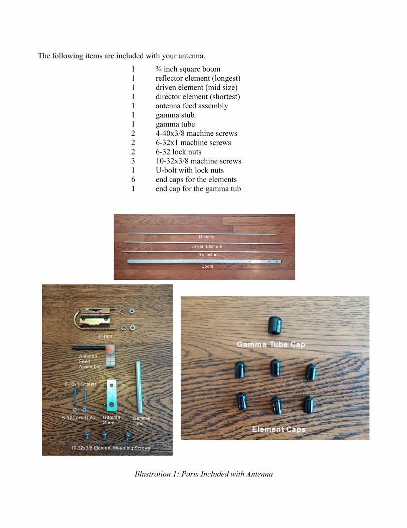
The following items are included with your antenna.
1 ¾ inch square boom
1 reflector element (longest)
1 driven element (mid size)
1 director element (shortest)
1 antenna feed assembly
1 gamma stub
1 gamma tube
2 4-40x3/8 machine screws
2 6-32x1 machine screws
2 6-32 lock nuts
3 10-32x3/8 machine screws
1 U-bolt with lock nuts
6 end caps for the elements
1 end cap for the gamma tub
Illustration 1: Parts Included with Antenna

Step 1 – Insert Elements
Insert all three elements into the boom. The longest one is located just in front of the U-bolt mounting
holes and the smallest one is at the opposite end. The mid length element is placed in the middle.
When finished the antenna should look like this:
Illustration 4:
Illustration 2: Element Inserted in Boom
Illustration 3: Antenna with Elements Installed

Step 2 – Centre and Secure Elements
Thread the 10-32x3/8 machine screws into the boom. Making sure the element is centered, carefully
tighten the screw against the element. Be careful not to over tighten and break the element. (You can
use a measuring tape or yard/metre stick to check each side is equal in length.)
Step 3 – Prepare Shorting Stub
Thread two 4-40x3/8 machine screws into the shorting stub as shown
Illustration 4: 10-32x3/8 machine screw holding element in place
Illustration 5: Gamma Shorting Stub
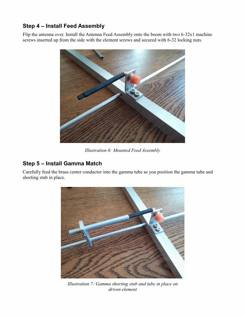
Step 4 – Install Feed Assembly
Flip the antenna over. Install the Antenna Feed Assembly onto the boom with two 6-32x1 machine
screws inserted up from the side with the element screws and secured with 6-32 locking nuts.
Step 5 – Install Gamma Match
Carefully feed the brass center conductor into the gamma tube as you position the gamma tube and
shorting stub in place.
Illustration 6: Mounted Feed Assembly
Illustration 7: Gamma shorting stub and tube in place on
driven element
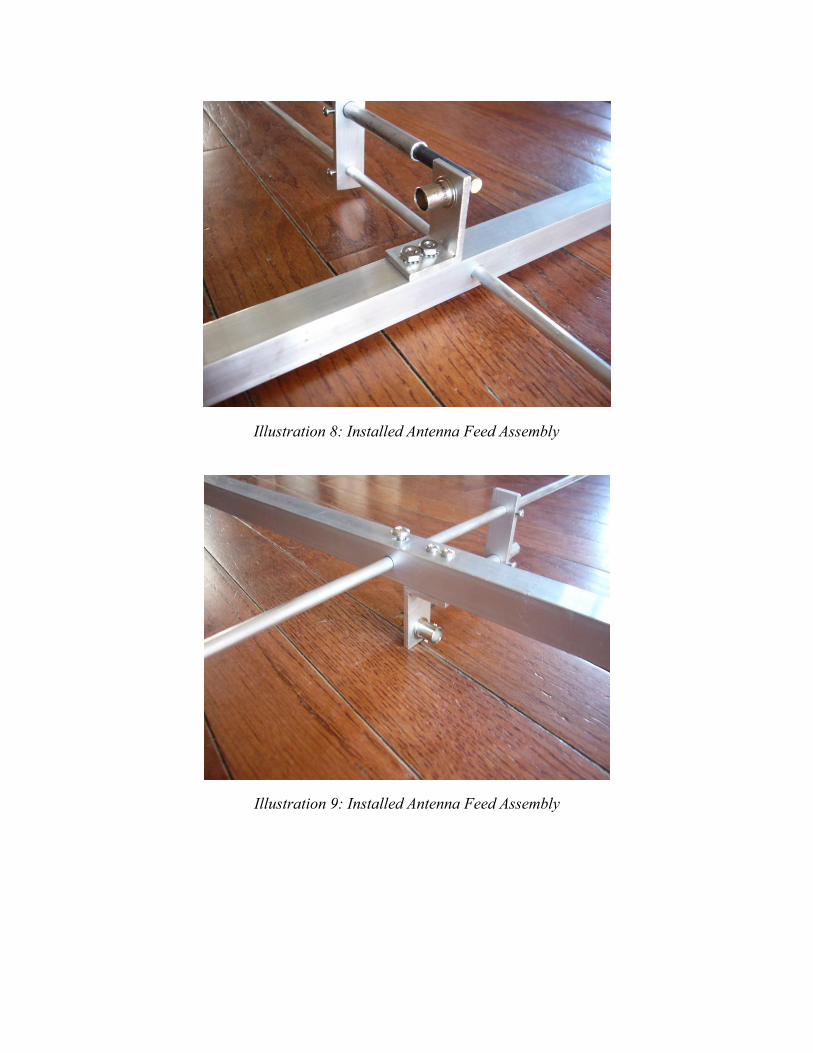
Illustration 8: Installed Antenna Feed Assembly
Illustration 9: Installed Antenna Feed Assembly

Step 6 – Install U-Bolt
Install the U bolt in the mounting holes at the end of the boom in the orientation required for mounting
the antenna.
Illustration 10: U-Bolt Installed

Step 7 – Install End Caps
Install the end caps on the elements and the gamma tube.
Illustration 12: Gamma Tube End Cap Installed
Illustration 11: Element End Cap Installed

Step 8 – Adjust Gamma Match
For approximate tuning, adjust the gamma tube and gamma stub to the following dimensions and
tighten the set screws. Adjust dimension A and tighten the element screw before moving onto
dimension B. For best performance use an Antenna Analyzer to optimize the tuning.
Antenna Type Dim A Dim B
147-149MHz 76mm 55mm
149-151 MHz 68mm 44mm
151-152 MHz 89mm 15mm
164-166 MHz 66mm 45mm
Note: 150MHz, 165MHz and 173MHz antennas have different element element lengths and one cannot
be tuned into the other frequency range.
Your antenna assembly is now complete. For best performance, mount your antenna clear of all metal
objects to a distance of at least ½ metre. The supporting mast through the U-bolt may be metal.
When mounting the antenna vertically, we recommend that the antenna is mounted so that the gamma
tube is up. This will prevent water from accumulating in the gamma tube.
Illustration 13: Gamma Match Dimensions

As previously mentioned, for most accuracy and best performance, we recommend purchasing an
antenna analyzer like the AA-520 so you can measure and fine tune your gamma match for the lowest
SWR (see www.rigexpert.com).
Illustration 14: RigExpert Antenna Analyzer