Embed Size (px)
Citation preview
96 Instrumental analysis
3 - Atomic Absorption Spectroscopy
Introduction
Atomic-absorption (AA) spectroscopy uses the absorption of
light to measure the concentration of gas-phase atoms. Since
samples are usually liquids or solids, the analyte atoms or ions
must be vaporized in a flame or graphite furnace. The atoms
absorb ultraviolet or visible light and make transitions to higher
electronic energy levels. The analyte concentration is
determined from the amount of absorption. Applying the Beer-
Lambert law directly in AA spectroscopy is difficult due to
variations in the atomization efficiency from the sample matrix,
and nonuniformity of concentration and path length of analyte
atoms (in graphite furnace AA). Concentration measurements
are usually determined from a working curve after calibrating
the instrument with standards of known concentration.
Schematic of an atomic-absorption experiment

97 Instrumental analysis
Relationship between Atomic Absorption and Flame Emission:
• Flame Emission: it measures the radiation emitted by the
excited atoms that is related to concentration.
• Atomic Absorption: it measures the radiation absorbed by
the unexcited atoms that are determined.
• Atomic absorption depends only upon the number of
unexcited atoms; the absorption intensity is not directly
affected by the temperature of the flame.
• The flame emission intensity in contrast, being dependent
upon the number of excited atoms, is greatly influenced
by temperature variations.
Flame Atomic Absorption Spectrometer

98 Instrumental analysis
Emission Flame Photometer
Advantages of AAS:
1. Widespread application to metals more than X-ray, Fluo,
FP
2. High sensitivity
3. No interference
Disadvantage of AAS:
1. Metal only (not for non –metals)
2. Cant be used for gas or solid (must dissolved first)
3. Only one element
4. Anionic interference (calibration curve with interfering
sub.)
Instrumentation
Light source: The light source is usually a hollow-cathode
lamp of the element that is being measured. The

99 Instrumental analysis
disadvantage of these narrow-band light sources is that only
one element is measurable at a time.
1. Hollow-cathode Lamps
Hollow-cathode lamps (HCL) are a type of discharge
lamp that produce narrow emission fr om atomic species.
The hollow cathode lamp uses a cathode made of the
element of interest with a low internal pressure of an inert
gas.
A low electrical current (~ 10 mA) is imposed in such a
way that the metal is excited and emits a few spectral
lines characteristic of that element (for instance, Cu 324.7
nm and a couple of other lines; Se 196 nm and other lines,
etc.).
The light is emitted directionally through the lamp's
window, a window made of a glass transparent in the UV
and visible wavelengths.
Schematic of a hollow-cathode lamp.
How cathode lamps work

100 Instrumental analysis
The lamp is filled with an inert gas like argon or neon. When a
potential is applied, It causes gas to become excited and it is
driven towards to cathode.
Metal atoms are than sputtered off
the surface of the cathode
M* -----> M0 + hv
Repeated bombardment of the metal atom by the gas causes
it to be excited. It ultimately relaxes, producing specific atomic
emission lines.
Electrodeless discharge lamps EDL
These provide radiant intensities that are usually one to
two orders of magnitude greater than hollow cathode
lamps. A typical lamp is constructed from a sealed quartz
tube containing a few torr of an inert gas such as argon
and a small quantity of the metal (or its salt) whose
spectrum is of interest.

101 Instrumental analysis
The lamp is energized by an intense field of radio-
frequency or microwave radiation. Ionization of the argon
occurs to give ions that are accelerated by the high-
frequency component of the field until they gain sufficient
energy to excite the atoms of the metal whose spectrum
is sought. Electrodeless discharge lamps are available
commercially for 15 or more elements.
Common discharge lamps and their wavelength ranges
are:
– hydrogen or deuterium : 160 - 360 nm.
– mercury : 253.7 nm, and weaker lines in the near-uv
and visible.
– Ne, Ar, Kr, Xe discharge lamps : many sharp lines
throughout the near-uv to near-IR.
– xenon arc : 300 - 1300 nm
Deuterium lamps are the Uv source in Uv-Vis absorption
spectrophotometers.

102 Instrumental analysis
How an EDL Works
• An intense RF (or microwave) field is applied to the sealed
quartz tube within the lamp
• Ar gas within the tube ionizes and gains kinetic energy
from the RF field
• Energy is transferred to the metal upon collision
• Excited metal returns to ground state, emitting light (hn)
Atomizer
Flame Atomization: In a flame atomizer, a solution of the
sample is nebulized by a flow of gaseous oxidant, mixed with a
gaseous fuel, and carried into a flame where atomization
occurs. The following processes then occur in the flame.
• Desolvation (produce a solid molecular aerosol)
• Dissociation (leads to an atomic gas)
• Ionization (to give cations and electrons)
• Excitation (giving atomic, ionic, and molecular emission)
103 Instrumental analysis
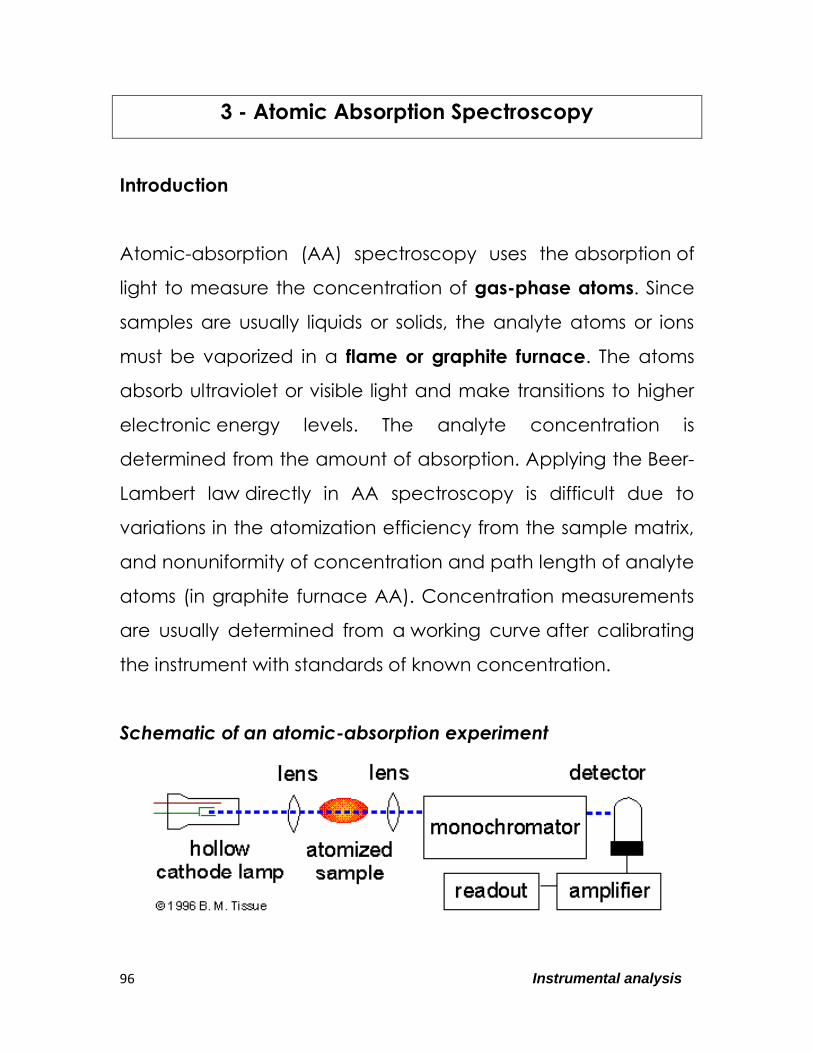
The Atomization Process
Types of Flames:
Several common fuels and oxidants can be employed in flame
spectroscopy depending on temperature needed.
Temperatures of 1700oC to 2400oC are obtained with the
various fuels when air serves as the oxidant. At these
temperatures, only easily decomposed samples are atomized.
For more refractory samples, oxygen or nitrous oxide must be
employed as the oxidant. With the common fuels these
oxidants produce temperatures of 2500oC to 3100oC.
Types of fuel/oxidant
1) air/acetylene 2300oC most widely used.
C2H2 + 2.5 O2 + 10 N2 → 2CO2 + H2O + 10N2
2) nitrous oxide/acetylene 2750oC hot and reducing red
feather zone
C2H2 + 5N2O → 2 CO2 + H2O + 5N2

104 Instrumental analysis
Burning Velocity:
The burning velocities are of considerable importance
because flames are stable in certain ranges of gas flow rates
only. If the gas flow rate does not exceed the burning velocity,
the flame propagates itself back in to the burner, giving
flashback. As the flow rate increases, the flame rises until it
reaches a point above the burner where the flow velocity and
the burning velocity are equal. This region is where the flame is
stable. At higher flow rates, the flame rises and eventually
reaches a point where it blows off of the burner.

105 Instrumental analysis
Flame Structure:
Important regions of a flame
include:
1. Primary combustion zone:
Thermal equilibrium is ordinarily
not reached in this region, and it
is, therefore, seldom used for
flame spectroscopy.
2. Interzonal region: This area is
relatively narrow in stoichiometric hydrocarbon flames, is
often rich in free atoms and is the most widely used part of
the flame for spectroscopy.
3. Secondary combustion zone: In the secondary reaction
zone, the products of the inner core are converted to
stable molecular
oxides that are
then dispersed into
the surroundings
Temperature Profiles:
A temperature profile
of a typical flame for
atomic spectroscopy is
shown in Fig. 9-3. The
maximum
106 Instrumental analysis
temperature is located in the flame about 1 cm above the
primary combustion zone. It is important– particularly for
emission methods – to focus the same part of the flame on
the entrance slit for all calibrations and analytical
measurements.
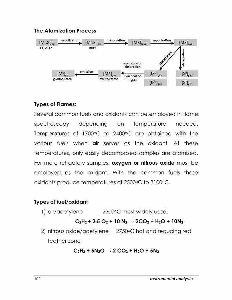
Flame Atomizers:
Figure below is a diagram of a typical commercial laminar flow
burner that employs a concentric tube nebulizer. The aerosol is
mixed with fuel. The aerosol, oxidant, and fuel are then burned
in a slotted burner that provides a flame that is usually 5 or 10
cm in length.
107 Instrumental analysis
Advantages:
1. Uniform drop size
2. Homogeneous flame
3. Quiet flame and a long path length
Disadvantages:
1. Flash back if Vburning > Vflow
2. ~90% of sample is lost
3. Large mixing volume
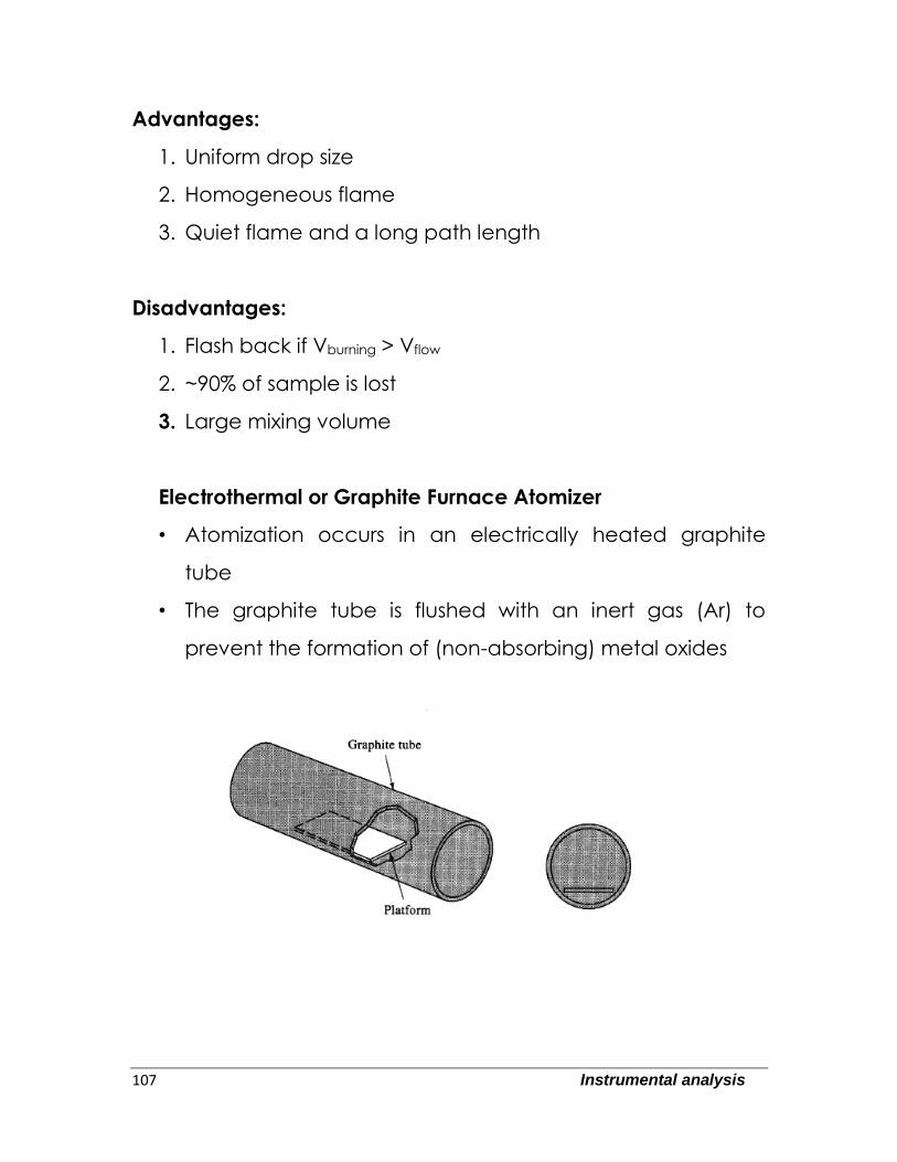
Electrothermal or Graphite Furnace Atomizer
• Atomization occurs in an electrically heated graphite
tube
• The graphite tube is flushed with an inert gas (Ar) to
prevent the formation of (non-absorbing) metal oxides

108 Instrumental analysis
Performance Characteristics:
Electrothermal atomizers offer the advantage of unusually high
sensitivity for small volumes of sample. Typically, sample
volumes between 0.5 and 10 L are used; absolute detection
limits lie in the range of 10-10 to 10-13 g of analyte. Furnace
methods are slow-typically requiring several minutes per
element. A final disadvantage is that the analytical range is
low, being usually less than two orders of magnitude.
Light separation and detection
AA spectrometers use monochromators and detectors for uv
and visible light. The main purpose of the monochromator is to
isolate the absorption line from background light due to
interferences. Simple dedicated AA instruments often replace
the monochromator with a band pass interference
filter. Photomultiplier tubes are the most common detectors for
AA spectroscopy.
Ionic spectra versus atomic spectra:
• Spectra of excited atoms differ from those of excited ions
of the same atoms
• Spectrum of singly ionized atom is similar to the atomic
spectrum of the element having an atomic number of
one less e.g.:

109 Instrumental analysis
– spectrum of Mg + is similar to that of Na atom
– spectrum of Al+ is similar to that of Mg atom
• Ionic spectra contain more lines than atomic spectra;
however the intensity of ionic spectra is much less than
that of atomic spectra.
Spectral Line width
• Narrow line desirable for
absorption and emission
work to reduce possibility
of interference due to
overlapping spectra.
• Theoretically atomic lines
should have a zero line
width but this does not
exist
• The natural line should have a width of 10-5 nm