Embed Size (px)
Citation preview

TECHNICAL REPORT GL-91-1
CONCRETE PAVING BLOCKS:FACILITIES ENGINEERING APPLICATIONSPROGRAM (FEAP) DEMONSTRATION, FY89
by
Gary L. Anderton
cGeotechnical Laboratory
DEPARTMENT OF THE ARMY'3 Waterways Experiment Station, Corps of Engineers3909 Halls Ferry Road, Vicksburg, Mississippi 39180-6199
C)7
ltFeb~rua ry 1991
Final Report
1 .,Approved For Public Release, Distribution Unlimited
[ABO,&.[~y' Prepared for US Army Engineering and Housing Support Center~Fort Belvoir, VA 22060-5516
N304 068

Destroy this report when no longer needed. Do not returnit to the originator.
The findings in this report are not to be construed as an officialDepartment of the Army position unless so designated
by other authorized documents.
The contents of this report are not to be used foradvertising, publication, or promotional purposes.
Citation of trade names does not constitute anofficial endorsement or approval of the use of
such commercial products.

Form Approved
REPORT DOCUMENTATION PAGE OM No 4o 8
PubA reporting burden for this collection of information is estimate to avera e i hour per response, including the time for re swng instructions searrhing ex~sting data sources,gatherngc and m aitaming the data needed, and completing a, I reviewingj the collection of information Send comments recjardingj this burden estimate Of anv Other aspect o0 thIscollection of informatton, includingj suggcestions for reducingj this burdlen to Washington Headquarters Services, Directorate fo information Ope rations and Repot$s, 12iS JeffersonDavis Higjhway, Suite 204. Arlington, VA 22202-4302. and to !,he Office of Management and Budgjet. Paperwork Rteduction Project (0704-0188), Washington, DC 20503
1. AGENCY USE ONLY (Leave blank) 2. REPORT DATE 3. REPORT TYPE AND DATES COVERED
February 19913 Final Re)ort4. TITLE AND SUBTITLE 5. FUNDING NUMBERSCONCRETE PAVING BLOCKS: Facilities EngineeringApplications Program (FEAP) Demonstration, FY89
6. AUTHOR(S)
Gary L. Anderton
7. PERFORMING ORGANIZATION NAME(S) AND ADDRESS(ES) 8. PERFORMING ORGANIZATION
REPORT NUMBERUSAE Waterways Experiment StationGeotechnical Laboratory T c n c l R p r3909 Halls Ferry Road Tecnic91 RporVicksburg, MS 39180-6199 G- -
g. SPONSORING/ MONITORING AGENCY NAME(S) AND ADDRESS(ES) 10. SPONSORING /MONITORING
US Army Corps of Engineers AGENCY REPORT NUMBER
Engineering and Housing Support Center FEAP-TR-91/01Bldg. 2593Fort Belvoir, VA 22060-5516
11. SUPPLEMENTARY NOTES
Available from National Technical Information Service, 5285 Port Royal Road,Springfield, VA 22161
12a. DISTRIBUTION / AVAILABILITY STATEMENT 12b. DISTRIBUTION CODE
Approved for Public Release; Distribution Unlimited
13. ABSTRACT (Maximum 200 words)This report documents a field demonstration of the construction of a concrete
block pavement at Aberdeen Proving Ground, MD. The block pavement was used to re-construct a tank road intersection which was previously surfaced with unboundgravel and was suffering from continual maintenance problems.
A general description and history of concrete paving blocks are provided, asell as detailed discussions of the design and construction techniques used for th(
demonstration project. The current Corps of Engineers Guide Specification for theconstruction of concrete block pavements is provided in Appendix C.
By monitoring the performance of the block pavement, it was determined thatthe design and construction methods demonstrated by this study were valid. After1 year of service, the block pavement continiues to perform satisfactorily underdaily tracked vehicle traffic. Concrete block pavements were proven as a viablepavement surfacing alternative for military tracked vehicles. Additional testsections and demonstration projects are proposed to validate the use of block pave-ments on airfields, port facilities, and motor pool areas.14. SUBJECT TERMS 15. NUMBER OF PAGES
Block pavement Pavement design 59
Concrete paving block Paving block 1 C16. PRICE CODE
Pavement construction Tracked vehicle17. SECURITY CLASSIFICATION 18. SECURITY CLASSIFICATION 19. SECURITY CLASSIFICATION 20. LIMITATION OF ABSTRACT
OF REPORT OF THIS PAGE OF ABSTRACT
Unclassified Unclassified UnclassifiedNSN 7540-01-280-5500 Staridard Form 298 (Rev 2 R9)
PsMcrtbed by ANY ld . 18298 '02

PREFACE
The US Army Engineering and Housing Support Center sponsored this
concrete paving block demonstration as part of the O&MA Program, Facilities
Engineering Application Program (FEAP), FY88, FY89 and FY90. The FEAP
Technical Monitor was Mr. R. W. Williams; Mr. K. Gregg was the Technical
Proponent group chairman. The project was coordinated by the Geotechnical
Laboratory (GL), US Army Engineer Waterways Experiment Station (WES),
Vicksburg, MS. The demonstration project took place at Aberdeen Proving
Ground, MD. It was designed in 1988, built in 1989, and monitored through
1990.
The project was conducted under the general supervision of Dr. W. F.
Marcuson III, Chief, GL, Messrs. H. H. Ulery, Jr., Chief, Pavement Systems
Division (PSD), GL, and L. N. Godwin, Chief, Materials Research Center, PSD.
This report was written under the direct supervision of Mr. T. W. Vollor,
Acting Chief, Material Research and Construction Technology Branch, PSD. The
WES FEAP Project Manager was Mr. R. H. Grau, PSD. Photographic support was
provided by Mr. G. E. Dill of the Visual Production Center. Construction
support was provided by Mr. P. C. Mijares, Jr., US Army Corps of Engineers,
Baltimore District. The project Principal Investigator was Mr. G. L. Anderton
who also wrote the report.
Commander and Director of WES during the conduct of the project and
preparation of this report was COL Larry B. Fulton, EN. Technical Director
was Dr. Robert W. Whalin.
I .,.. . . . .. . . . .. ... ... ..

CONTENTSPage
PREFACE................................................................... 1I
CONVERSION FACTORS, NON-SI TO SI(METRIC) UNITS OF MEASUREMENT........................................ 3
PART I: INTRODUCTION..................................................... 4
Description........................................................... 4History............................................................Purpose of Report..................................................... 6
PART II: DEMONSTRATION ................................................. 7
Objective............................................................. 7Site Conditions....................................................... 7Design................... ............................................ 8Construction Techniques............................................... 8Initial Traffic Testing.............................................. 11
PART III: PERFORMANCE MONITORING........................................ 12
PART IV: ECONOMICS...................................................... 14
PART V: ADVANTAGES AND DISADVANTAGES.................................... 16
Advantages........................................................... 16Disadvantages........................................................ 17
PART VI: CONCLUSIONS AND RECOMMENDATIONS................................ 18
Conclusions.......................................................... 18Recomuendat ions....................................................... 18
REFERENCES............................................................... 19
FIGURES 1 - 30
APPENDIX A: CONCEPT DESIGN ANALYSIS..................................... Al
APPENDIX B: CONCRETE BLOCK PAVEMENT DESIGN.............................. Bl
APPENDIX C: CONCRETE BLOCK PAVEMENT GUIDE SPECIFICATION ................. Cl
9

CONVERSION FACTORS, NON-SI TO SI (METRIC)UNITS OF MEASUREMENT
Non-SI units of measurement used in this report can be converted to SI
(metric) units as follows:
Multiply By To Obtain
cubic yards 0.7645549 cubic metres
degrees (angle) 0.01745329 radians
feet 0.3048 metres
inches 2.54 centimetres
miles per hour (international) 0.4476 metres per second
pounds (force) 4.448222 newtons
pounds (force) per square inch 6.894757 kilopascals
pounds (mass) per cubic foot 16.01846 kilograms per cubic metre
square feet 0.09290304 square metres
tons (mass)(2,000 pounds) 907.1847 kilograms
3

CONCRETE PAVING BLOCKS: FACILITIES ENGINEERING APPLICATIONS
PROGRAM (FEAP) DEMONSTRATION, FY89
PART I: INTRODUCTION
Description
1. A concrete paving block is an accurately dimensioned combination of
well-graded aggregates and hydrated portland cement which fits closely
together with other paving blocks to form a pavement slrface. The blocks are
manufactured in a wide variety of shapes, some of which are shown in Figure 1.
Generally, the blocks are about the size of a common brick with a thickness of
2-3/8 to 4 in.* and weigh about 9 to 12 lb each.
2. A thin, 1- to 2-in.-thick leveling course of sand is used under the
blocks. The blocks are generally laid by hand on a sand layer. The blocks
are then compacted with a manually operated vibratory plate compactor which
seats the blocks in the sand layer, compacts the sand layer, and forces some
sand into the joints between the blocks. Additional sand is then applied to
the surface and swept into the joints between the blocks. More passes are
made with the vibratory plate compactor to compact and wedge the sand into the
joints. A base and subbase course under the leveling course provides
sCtructura support similar to that of a conventional flexible pavement.
ligtu're 2 shows a generalized cross section of a block pavement. Many
different patterns for laying blocks are possible, and several patterns are
illustrated in Figure 3.
3. Concrete block pavements provide a low-maintenance, high-strength
pavement: surface that resists heavy, concentrated, or abra-;ive loads and
chemica1l ';pil1s .,volving fuel, hydraulic fluid, and other materials. Their
mod.lar Imtotre ai'd potential for reuse allow easy removal and replacement for
access: to bua-ied ut llit es or t.o correct settlement. A block pavement's
utlil,, c ha mc tel: ;t itc; (st rtengthj , abrasion resistance, flexible structure, and
esthetics) make it applicable to m.ny pavement uses, including military
A table of factor:; for convert ing non-SI units of measurement to SI (metric)
on t a i rs;i (1Onl page 3.
4

History
4. The use of concrete blocks in pavements is recognized as the latest
development in the long history of modular paving elements. The first record
of stone paving goes back to 4000 B.C. in Assyria; clay brick paving was used
in India in 3000 B.C. History tells us that the ancient Romans used blocks of
hand-crafted stone in pavements throughout the Roman Empire. The Dutch have
documented the use of natural stones and wood in urban streets throughout The
Netherlands since the Middle Ages.
5. Before World War II, the traditional pavement surface course in many
areas of Western Europe was the rectangular clay brick. After World War II,
populations in Western Europe became more decentralized, and the demand for
paving blocks grew enormously, especially since clay bricks were urgently
required to rebuild buildings destroyed in the war. As a result of this
demand, the concrete paving block was first introduced in The Netherlands in
1951 as an alternative to the traditional clay brick (Sharp and Armstrong
1985). Since most European countries had established histories of paving with
stone blocks, the concrete block pavements were readily accepted, and their
use has steadily increased in Europe since their introduction.
6. Concrete paving blocks were first produced in the United States in
the 1960's usiig German production equipment and designs. At first, concrete
paving blocks were used in the United States primarily for their aesthetic
value in sidewalks, courtyards, driveways, and parking areas in expensive
developments. Recently, paving blocks have been recognized for their
potential in heavy-load pavement applications. Concrete block pavements have
been used in low-speed, heavily-trafficked urban streets, port facility
loading terminals, and, most recently, on airfield taxiways at the Dallas/
Fort Worth International Airport. The concrete paving block market is still
developing in the United States and is expected to expand considerably in the
near future.
7. Previous research at the US Army Engineer Waterways Experiment
Station (WES) using heavy truck and tank traffic (Rollings 1983) has resulted
in interim design guidelines for the Corps of Engineers. The design is
similar to that for flexible pavement guidelines, except that the block and
sand bedding layer is assumed to be equivalent to 6.5 in. of asphalt concrete
5

surfacing. This equivalency factor is based upon the standard 60-mm- or
80-mm-thick paving blocks.
Purpose of Report
8. This report documents the concrete paving block FEAP project at
Aberdeen Proving Ground, MD, which was designed in FY88, constructed in FY89,
and monitored in FY90. This report also provides general guidance for the
design, construction, and use of concrete paving blocks as pavement
surfacings.
6

PART II: DEMONSTRATION
Objective
9. The main objective of this demonstration is to familiarize the
Directorate of Engineering and Housing (DEH) community with the latest
concrete paving block technology. However, the project directly affected the
installation where the demonstration was conducted by solving a local pavement
problem with a solution designed to reduce significantly future maintenance
costs.
Site Conditions
10. The demonstration site at Aberdeen Proving Ground, MD, was
identified as an unsurfaced tank road intersection located on the outer rim of
the Tank Retrieval Range Area. The intersection brought five range roads
together near a tracked vehicle motor pool area. The traffic count for this
intersection was estimated at 10 M-88 (56 ton) Tank Retrievers and 10 M-578
(30 ton) tracked vehicles per day. Approximately 12,000 sq ft of the existing
gravel surfaced intersection was scheduled for reconstruction using the
concrete paving blocks as the new pavement surfacing.
11. The existing subgrade was relatively weak (Design CBR 3) and when
combined with heavy seasonal rains, the intersection required constant
maintenance and regrading in order to remain functional. An economical
surfacing of the intersection required a flexible pavement in order to
withstand the settling conditions caused by the weak subgrade. Traditional
flexible pavement surfacings, such as asphalt concrete, would not have
withstood the abrasive action of the turning tracked vehicles. The
combination of a soft subgrade and tracked vehicle traffic made the Aberdeen
Proving Ground site a good candidate for the concrete paving block
demonstration.
7

Des On
12. The demonstration project at Aberdeen Proving Ground, MD, was
designed by the US Army Corps of Engineers, Baltimore District, with ne
assistance of WES personnel, particularly on the concrete block pavement
design. The details of the site evaluations and laboratory tests are
contained in Appendix A.
13. The design of the concrete block pavement was based on the Corps of
Engineers standard flexible pavement design as prescribed in Technical Manual
TM 5-822-5/AFM 88-7, Chapter 3 (Headquarters, Departments of the Army and Air
Force 1971). The thickness requirements of the base and subbase layers were
computed based on the in-situ soil properties and equating the concrete block
and sand bedding layers with 6.5 in. of asphalt concrete surfacing. Details
of the pavement thickness design prcedure are found in Appendix B.
14. The design results indicated that the total reconstructed pavement
thickness, excluding recompacted subgrade, would be approximately 27 in. The
pavement layers, from bottom to top, consisted of 12 in. oF recompacted
existing subgrade material, a geotextile for separation of subgrade and
subbase, 19 in. of select-fill compacted in lifts as the subbase, 4 in. of
crushed stone base course, 1/2 in. (final thickness) sand bedding layer, and
3.15-in.- (80 mm) thick paving block. The rectangular shaped paving block was
specified since previous research had indicated that this block shape was
appropriate for heavy-duty applications (Rollings 1983, Knapton 1984, and
Kuipers 1984). A crosssection of the designed pavement layers is found in
Appendix B.
Construction Techniques
15. Construction of the demonstration project at nberdeen Proving
Ground began in May 1989. At this time, the intersection was in relatively
good condition as a result of an extended period of low rainfall (Figure 4),
There were several areas of the intersection which had excessive amounts of
fine aggregates and silts on the surface. This resulted from the tracked
vehicles carrying these mater Liais onto the gravel surface from the unsurficed
range roads leading to the imt rs .ction. When these areas became wet, the

effectiveness of the gravel surfacing was significantly reduced, and
additional gravel was required to resurface these areas. This continuing
cycle of required maintenance was to be eliminated by surfacing the
intersection with concrete paving blocks.
16. The first step in the construction process was to erect silt fence
barriers around the intersection (Figure 5) to prevent excessive silt runoff
during the earthwork stage. Next, a total of 27 in. of the existing soil was
removed (Figure 6), and the existing subgrade was compacted to meet the
specified density requirements (Figure 7). The required density of the
subgrade was at leaL.t 90 percent of the CE-55 maximum density. A geotextile
was placed on top of the compacted subgrade (Figure 8), and a select-fill
subbase material was spread and compacted over the geotextile in several lifts
(Figures 9 and 10). The geotextile specified was a Mirafi 600X subgrade
stabilization fabric, or equivalent. To complete the base and subbase
construction, a 4-in. crushed stone base course was placed and compacted over
the subbase (Figure 11). The required density of both the subbase and base
course layers was 100 percent of the CE-55 maximum density.
17. After the final compaction and grade requirements for the base
course were achieved, a cast-in-place concrete curb was built around the
interseption area. A commercial slipform type curb machine was used for this
proccss. The concrete curb was constructed at a 3-1/2-in. height differential
from the surfacc of the base course to match the final thickness of the paving
block and sand bedding layers. The curb would act as the required edge
restraint to prevent the paving blocks from shoving under traffic.
18. Once the concrete curbs had sufficiently cured, construction of the
paving block system began. A sand bedding layer was placed over an area of
the compacted base estimated to equal 'o 1 day's coverage of paving blocks.
The sand used for the bedding layer was clean and well graded, meeting the
specification requirements listed in Appendix C. The sand was dumped and
spread over this area (Figure 12) with the use of screeding pipes. The pipes
were I in. outside diameter and were used along with a wooden screeding board
to achieve the specified 1-in. initial depth (Figure 13). After screeding the
1-in. sand bedding layer on both sides of the screeding pipe, the pipe was
carefully pulled and the resulting void in the sand layer was filled and
screeded with a small piece of wood mounted on a broom handle.
9

19. The paving blocks were handlaid beginning at the center edge of one
of the road entrances (Figure 14). A stringline was set up perpendicular to
this curb edge to run from the start point through the center of the
intersection. The stringline served as a reference point to begin and keep
all block placement in perfect alignment. This technique was necessary since
the concrete curbs surrounding the intersection area were curved and were in
no particular alignment.
20. The herringbone pattern of block placement (described in
Appendix B) was carefully established at the beginning of the block placement
phase as the alignment of the entire block pavement depended on the initial
blocks. The paving blocks were placed directly on the 1-in. sand bedding
layer (Figure 15). The resulting height differential at the curb was 3/4 in.
(Figure 16) to allow for 1/2-in. settlement of the sand bedding layer during
compaction and an additional 1/4-in. estimated settlement of the underlying
layers under traffic.
21. Near the end of each day's production, the newly laid paving blocks
were compacted with several passes of a manually operated vibratory plate
compactor (Figure 17). No compaction was allowed within 5 ft of the
unfinished paving block edge in order to prevent the paving blocks from
shoving outward. Once the paving blocks had been compacted, a fine-graded
masonry sand was spread over the paving blocks (Figure 18) and broomed into
the joints. This jointing sand had a considerably finer gradation (as
described in Appendix C) than the bedding layer sand. Several passes of the
vibratory plate compactor consolidated this jointing sand (Figure 19). The
spreading and vibrating of the jointing sand was repeated several times until
all paving block joints were filled.
22. The paving blocks were trimmed to the required dimensions and
placed along the concrete curb edge restraint as the work progressed. Each
block cut was measured by placing the block over the open area and marking the
required cut line with chalk. A hand-operated splitting device was used to
oreak the block along the cut line (Figure 20). This device produced a
retatively clean and straight break. A slight angle was provided on every
break to make the top surface approximately 1/4 in. longer (or wider) than the
bottom surface. This chamfered edge helped the paving block to fit into the
desired space much easier (Figure 21). Once a length of the pavement edge had
10

been trimmed in, the paving blocks were compacted and the joints filled in the
same manner as previously described. Figures 22 and 23 show a finished edge
before and after application of the jointing sand.
23. By the end of each working day, all areas of screeded bedding sand
were covered by paving blocks tc prevent disturbance of the sand bedding layer
before block placement and compaction. The paving block installation for the
entire 12,000 sq ft intersection was completed in approximately 16 working
days. The paving block installation crew generally consisted of one person
screeding sand and trimming in the edges, two people laying the paving blocks,
and two people carrying the paving blocks from nearby pallet stacks to the
block layers.
Initial Traffic Testing
24. The initial traffic testing of the block pavement took place on
the same day the construction was completed. A 56-ton M-88 Tank Retriever
(Figure 24), which was th." heaviest vehicle scheduled to traffic the
intersection, was used for the traffic tests. The M-88 first made several
low-speed straight passes through the intersection. The tank retriever next
performed high-speed breaking and acceleration maneuvers to check the block
pavement's lateral stability. Since no damage occurred with the straight line
maneuvers, the M-88 was allowed to make several 90-deg pivot steer turns.
Again, no damage to the block pavement occurred. Finally, the M-88 was
allowed to lock one track and perform several 360-deg pivot steer turns at
high speed (Figure 25). This maneuver is thought to be the most severe in
terms of surface abrasion from tracked vehicles. No damage to the block
pavement qas noticed; only scuff marks from the tracks' rubber pads were left
on the pavement surface (Figure 26).
11

PART III: PERFORMANCE MONITORING
25. The paving block demonstration site was monitored during its first
year of service to evaluate its field performance capabilities. Initial
communications with Aberdeen Proving Ground personnel indicated that the
concrete block pavement was performing exceptionally well with no reported
block failures or rutting problems. The only maintenance performed during the
first few months of use resulted from the tracked vehicles carrying a
considerable amount of mud onto the block pavement from the training ranges.
The mud was scraped off the pavement surface using a motor grader or dozer
blade. Although this is not a recommended practice, no damage to the paving
blocks was reported as a result of this maintenance procedure.
26. On 30 April 1990, WES personnel visited the demonstration site to
observe the pavement under traffic and to determine the general condition of
the concrete block pavement after 8 months of service. At this time, daily
traffic was reported to average 12 passes per day of the M-88 Tank Retriever
(Figure 27) in addition to several daily coverages from smaller tracked
vehicles. No visual surface abrasion damage was noted. Straight-edge
measurements were taken throughout the intersection area to determine if any
significant settling or rutting had occurred (Figure 28). Only three isolated
areas of slight wheel path rutting (< 3/8 in.) were found near the inter-
section entrance areas where the tracked vehicle traffic was noted to be the
most channelized. The straight-edge measurements and visual observations
indicated that the concrete block pavement had maintained its structural
integrity during its initial service life.
27. WES personnel visited the demonstration site again on 22 August
1990 to observe the concrete block pavement. At this time, the pavement had
been in service under daily traffic for approximately 1 year. Heavy rainfall
before and during this site visit had caused a great deal of mud to be tracked
onto the paving block intersection by the tracked vehicles (Figure 29). The
heavily trafficked areas were covered with 6 to 8 in. of mud (approximately
60 percent of the total block pavement surface), and most of the remaining
areas were covered with 1/2 to 1 in. of mud. Local personnel reported that
these muddy conditions were not uncommon and did not seem to adversely affect
the block pavementrs performance. A few areas of paving blocks were visible
12

(Figure 30), and these areas indicated that the paving blocks were in good
condition. Aberdeen Proving Ground personnel reported no major maintenance
for this pavement during its first year of service and were very satisfied
with the pavement's performance to date.
13

PART IV: ECONOMICS
28. The total cost of the paving block project at Aberdeen Proving
Ground was $126,743. This cost included all subbase and base course work, the
geotextile placed beneath the subbase, and all related incidentals and
miscellaneous expenses. The cost of obtaining and placing the paving blocks,
including all block and sand materials, labor, and equipment charges, was
$51,431. This translates into a cost of about $4.29 per sq ft for the paving
blocks on this job. The elimination of continual maintenance on this
intersection (including regrading, drainage reconstruction, and other work)
will result in long-term savings for the installation.
29. It was estimated that it would have cost approximately the same
amount to build an asphalt concrete surfaced pavement structure capable of
carrying the same traffic loads at this site. Building such an asphalt
concrete pavement would not have been advisable, however, as the abrasive
action of the turning tracked vehicles would have significantly shortened the
service life of an asphalt concrete surface. Because of the relatively small
surface area of the intersection, it was estimated that a portland cement
concrete (PCC) pavement designed for the demonstration site would have cost
between 10 and 30 percent more than the paving blocks for initial construc-
tion. Maintenance costs would likely have been high for a PCC pavement,
resulting from costly crack repair, slab failures, and moisture damage. The
concrete block pavement is expected to require virtually no maintenance
throughout its 20-year design life.
30. In general terms, the cost of paving blocks vary considerably due
to local differences in labor, material, block quality and size, and
transportation costs (Rollings 1983). For large scale applications in the
United States, block pavements are usually more expensive than conventional
paving materials in terms of construction costs. Under some conditions, such
as those of the demonstration site, the maintenance cost savings realized by
using paving blocks instead of conventional paving materials give the paving
block alternative the economic advantage.
31. The market for concrete block pavements is currently growing in the
United States. More manufacturers are producing paving blocks to meet the
increasing demands, thereby reducing freight costs in many areas. The number
14

of block paving contractors is also increasing, creating a more competitive
market. It is anticipated that as the concrete paving block market grows in
the United States, the relative cost of materials and construction for block
pavements will decrease.
15

PART V: ADVANTAGES AND DISADVANTAGES
Advantages
32. There are many advantages in using concrete paving blocks under
certain conditions. Weighing these advantages against the disadvantages of
using concrete paving block is a much easier task when specific site
conditions such as sobgrade quality, material availability and cost, and
traffic conditions are known. Although certain site conditions may create
special benefits for using paving blocks, the following list comprises the
major reasons for using paving blocks as a pavement surfacing. Concrete
paving blocks:
a. Provide a flexible pavement surface which is composed of
durable, rigid materials.
b. Provide a low-maintenance or zero-maintenance pavement surface.
c. Can support large, concentrated loads and heavy, abrasive
traffic.
d. Can support heavy loads over relatively weak subgrades.
e. Are comparatively high-quality pavement materials as the blocks
ar centrally manufactured and tested before going to the jobsite.
f. Are resistant to environmental damage (e.g. freeze-thaw).
g. Are resistant to damage from fuel and oil spillage.
h. Allow for easy access to subsurface for utilities or subgrade
repair.
i. Are reusable (90 to 95 percent) after removing from an existingpavement surface.
i. Negate traffic delays because of curing (in relation to PCC).
k. Offer good skid resistance, wet or dry.
1. Are aesthetically pleasing.
16

Disadvantages
33. There are some disadvantages in using concrete paving blocks that
must be addressed when considering the block pavement alternative. Some of
the potential disadvantages could be lessened in the future as research and
market growth increase. The most prevalent disadvantages commonly attributed
to the concrete paving block alternative are:
a. Sometimes higher initial cost, depending on job size, pavementthickness, location, etc.
b. Labor intensive construction process.
9. Rideability (smoothness) problems at high speeds (greater than40 mph).
4. Water infiltration of underlying layers; therefore, no moisture
sensitive base materials may be used. (This problem is usuallyonly significant at the start of the pavement's service lifebefore solidification of the jointing material.)
e. Lack of experienced designers, contractors, and blocksuppliers.
17

PART VI. CONCLUSIONS AND RECOMMENDATIONS
Conclusions
34. The following conclusions are made, based on the findings of the
demonstration project:
a. The 80 mm-thick rectangular concrete paving blocks laid in theherringbone pattern can withstand the heavy, abrasive loading
conditions of military tracked vehicle traffic.
b. A concrete block pavement can support heavy loads over weaksubgrades when constructed with appropriate base and subbasecourses.
c. The current method of using the Corps of Engineers standardflexible pavement design with a 6.5-in, equivalent thicknessratio is a conservative but valid design method.
Recommendations
35. The following recommendations are made:
a. Concrete paving blocks should be considprcd as a pavementsurfacing alternative when traffic demands and other siteconditions makc Lhem economically feasible.
b. The concrete block pavement guide specification found inAppendix C should be used in future block pavementconstruction.
c. Additional test sections and demonstration projects are neededto develop other concrete paving block uses such as forairfields, port facilities, ard motor-pool areas.
d. Additional materials research is needed in the areas of blockstrength requirements and joint sealants for stabilizing
jointing sands.
18

REFERENCES
Headquarters, Departments of the Army and Air Force. 1971. "FlexiblePavements for Roads, Streets, Walks and Open Storage Areas," Technical ManualTM 5-822-5/AFM 88-7, Chapter 3, Washington, DC.
Knapton, J. 1984. "Concrete Block Pavement Design in the U.K.," Proceedings,Concrete Block Raving Second International Conference, pp 129-138, Delft, TheNetherlands.
Kuipers, G. 1984. "The Choice of an Appropriate Block Shape for HeavyIndustrial Flexible Pavements," Proceedings. Concrete Block PavingInternational Conference, pp 69-71, Delft, The Netherlands.
Rollings, R. S. 1983. "Concrete Block Pavements," Technical Report GL-83-3,US Army Engineer Waterways Experiment Station, Vicksburg, MS.
Sharp, K. G. and Armstrong, P. J. 1985. "Interlocking Concrete Block
Pavements," Special Report No. 31, Australian Road Research Board, Victoria,Australia.
19

Figure 1. Examples of paving block shapes (after Rollings 1983)
CONCRETE BLOCK SURFACE
" -SAND LEVELING COURSE '
BASE COURSE
C SUBBASE COURSE
SUBGRADE
Figure 2. Typical cross section of block pavement(after Rollings 1983)

a. Stretcher bond b. Herringbone
C. Parquet
Fijgure 3. Exampl1es of common laying pa tte rns (a ft erI Ro i ligs 1983)
\J\
Fi gtir I~ I (' i~'' /s Gl ,ur mfaced i nte rs-ect i onleal)11ore rrcous~lt rucrt i oll

Hi gtrc ) [: II', u silt fenice harriers
i ] t . i! t i l " ; I

.7
Vi p i r e 7. Ccipac ted subgrade
II t o f I l : Ic I t ) 1-,I(

Solect-fll subbae inateialb igsraove getxtl
44-T

F' i gu re I I A /-iii. - thick c rushed s tone b ase C on rS(
4pr~dilp e diIi,! l

Figure 13. Screeding 1-in. -thick bedding sand layer
Fi j'Ilro 1/j IHdIldiI pk(7 p (Concrete( javll ti hlioc1*:5

Fiur 15 Pain blck on to of -in.- -tc sand ,bedin layer,. t0) ,4
M41
1171u r
Figure/ 1.Pvnblcsotof 1i.tiksn
Figure 16. A 3/4- in.-height differetttAii to allow forcomipaict iof and settlement.

Figure 17. Initial compacting of paving blocks
Fig i18. Sp iid i ii, j c)intid u, sand over ceouplct tdpai1)Ic k'1zs

Figure 19. Vibrating jointing sand into paving blockjoints
Figure 20. Cutting paving block with hand splitter

77
Fiure 2. Trimmnge lc pavement deWith tbock
jo li i i' S n

:' .. .. .. -o p..- ;
Fi gure 23. 'rimmed edge of block pavement with jointiugsand
I t t If i c(Xi t 1

Figure 25. M-88 Tank Retriever performing 360-degree
locked wheel turns
tFipum-, 16. Rtubber" ti-ack marks left 011 to) Of UI1(IMTIIp d
jm,iirg block surface,

F igure 27. M-88 Tank Retriever on 8 -month olId block,:
paivemnent
44
1),,wk 4,r,,n'

Fi gure~ 29. Mud covered blockh pavement after 1 year of servicre

APPENDIX A: CONCEPT DESIGN ANALYSIS
Concrete Block PavementsAberdeen Proving Ground, MD
Concept Design Analysis
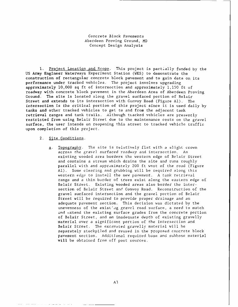
1. Proiect Location and Scope. This project is partially funded by theUS Army Engineer Waterways Experiment Station (WES) to demonstrate theconstruction of rectangular concrete block pavement and to gain data on itsperformance under tracked vehicles. The project involves upgradingapproximately 10,000 sq ft of intersection and approximately 1,150 ft ofroadway with concrete block pavement in the Aberdeen Area of Aberdeen ProvingGround. The site is located along the gravel surfaced portion of BelairStreet and extends to its intersection with Convoy Road (Figure Al). Theintersection is the critical portion of this project since it is used daily bytanks and other tracked vehicles to get to and from the adjacent tankretrieval ranges and tank trails. Although tiacked vehicles are presentlyrestricted from using Belair Street due to the maintenance costs on the gravelsurface, the user intends on reopening this street to tracked vehicle trafficupon completion of this project.
2. Site Conditions.
a. Topography. The site is relatively flat with a slight crownacross the gravel surfaced roadway and intersection. Anexisting wooded area borders the western edge of Belair Streetand contains a stream which drains the site and runs roughlyparallel with and approximately 200 ft west of the road (FigureAl). Some clearing and grubbing will be required along thiswestern edge to install the new pavement. A tank retrievalrange and a thin border of trees exist along the eastern edge ofBelair Street. Existing wooded areas also border the inter-section of Belair Street and Convoy Road. Reconstruction of thegravel surfaced intersection and the gravel portion of BelairStreet will be required to provide proper drainage and anadequate pavement section. This decision was dictated by theunevenness of the existing gravel road surface, a need to matchand extend the existing surface grades from the concrete portionof Belair Street, and an inadequate depth of existing gravellymaterial over a significant portion of the intersection andBelair Street. The excavated gravelly material will beseparately stockpiled and reused in the proposed concrete blockpavement section. Additional required base and subbase materialwill be obtained from off post sources.
A3

b. Subsurface Condi t ions.
(1) Exploration. On 18 April 1988, nine auger borings were
performed through the existing gravel surfacing on the roadand intersection and vxtended down into the clay subgrade.The borings were 7.5 ft deep except for auger boring PB-3which encountered auger refusal at 4 ft. Large bag sampleswere taken of the existing gravel surfacing material, and
auger samples were taken of the clay subgrade.
(2) Laboratory Testing. All samples were visually classifiedin the laboratory. Mechanical analyses, Atterberg limits,
and water contents wecre accomplished on representativesamples of the different gravel surfacing materials and the
clay subgrade.
(3) Soil Stratigra,)hy. The exi.;ting gravel surface of the road
and intersection consist of a conglomeration of cobbles,sandy gravels, and gravelly sands of variable thickness(0.8 to 3.5 ft). These fill materials are underlain by the
relatively soft natural sandy to silty clay subgrade.
(4) Ground water. No ground water problems are anticipated
during construction since ground water was not encounteredduring the drilling for this project, and the ground water
levels encountered at the adjacert Applied InstructionFacility (ground water elevation from 18.0 to 19.0 ft) are
significantly below our proposed excavations. However,control of surface water drainage both within the project
limits and from the adjacent sites will be important due tothe relatively flat grades throughout this area.
3. Pavement Desipn.
a. General . The concrete block pavements have been designed to
meet both strength and frost protection requirements in accord-
ance with the latest Department of the Army criteria. Thefollowing references were used in the design of the pavements:
1) TM-5-818-2, "Pavement Design for Season, I Frost Conditions"
(2) TM-5-822-2, "Gencral Provisions and Geometric Design forRoads , Streets, Walks, and Open Storage Areas".
(3) TM-5-822-5, "Engineering and Design of Flexible Pavementsfor Roads. Streets, and Open Storage Areas"
(4) Technical Report CL-83-3, "Concrete Block Pavements", March1983, US Arm, Enrimcr Waterways Experiment Station.
Letter, DAEN-JCWE-G, "Design of Gravel Surfaced Hlardstands",
7 March 19V.
A4

b. Subgrade Design Parameters. The subgrade is zlassified as anF-4 frost susceptibility group for frost design. Based on theCalifornia Bearing Ratio (CBR) test results from the adjacentApplied Instruction Facility (see Figure Al), and the relativelyhigh moisture content of the onsite clays, a design subgradeCBR - 3 will be used in the design. Due to the relatively lowstrength of the subgrade soils, a subgrade stabilization fabric(Mirafi 600X or equal) will be specified to assist in construc-tion and to reduce the required thickness of base/subbase courseover these subgrade soils.
. Existing Gravel Surface Material Design Parameters. A CBR rangeof 20 to 30 may be assumed for these materials with the finaldesign value depending on the results of the Atterberg limittests presently being performed. Although these materials havea significant percentage passing the No. 200 sieve (13 to 26percent), they also have a significant portion retained on theNo. 10 sieve (42 to 74 percent) and have performed satisfac-torily over several seasons of heavy tracked vehicle traffic.The primary deficiency of these materials has been theirinability to stand up to the churning action of the tracks, andthe need for a subgrade separation medium to prevent the gravelfrom penetrating into the relatively low strength subgradesoils. Therefore, due to the monetary restrictions on thisproject, the excavated existing gravel surfacing material shallbe reused as subbase course material in the proposed concreteblock pavement section. Based on a concept design CBR - 20 forthis material, and the 6.5 in. of equivalent asphalt surfacingand base course provided by the concrete block plus bedding sand(Reference: Technical Report GL-83-3), a 4-in. stone base coursewill be required over the existing gravel surfacing material tobe used as subbase course material.
d. Design Traffic. The traffic consists of all types of wheeledand tracked vehicles. The controlling vehicle is the trackedM 88 Tank Retrieval Vehicle (56 tons) which has a frequency of10 to 25 passes per day. Based on this category VII traffic, adesign index of 10 shall be used for the concept pavementdesign.
e. Pavement Section. The concept pavement design calculations, thedesign pavement section, and the concrete block lay down patternand installation notes are shown in Appendix B. Additionalmaterial and placement requirements on the concrete blockpavement are contained in Appendix C.
A5
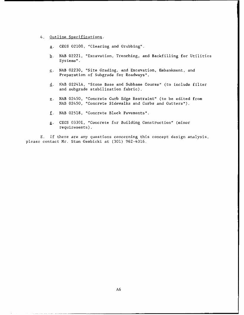
4. Outline Specifications.
a. CEGS 02100, "Clearing and Grubbing".
b. NAB 02221, "Excavation, Trenching, and Backfilling for UtilitiesSystems".
c. NAB 02230, "Site Grading, and Excavation, Embankment, andPreparation of Subgrade for Roadways".
d. NAB 02241A, "Stone Base and Subbase Course" (to include filterand subgrade stabilization fabric).
e. NAB 02450, "Concrete Curb Edge Restraint" (to be edited from
NAB 02450, "Concrete Sidewalks and Curbs and Gutters").
f. NAB 02518, "Concrete Block Pavements".
g. CEGS 03301, "Concrete for Building Construction" (minorrequirements).
E. If there are any questions concerning this concept design analysis,please contact Mr. Stan Gembicki at (301) 962-4316.
A6

*_ a:u.
/,. ) /I /jjII .- "1W (L
1:1
'---
- ' 7 . . '-.. .. ,, '.-... - -. . .i
... i '"/" .
,.- , , ;
- , i..i / .. io" :
.I.,
/ / -RD E .. I WG -- ,-- "300 0 ILSITE MAP
200- 'C
I ", '" IF%. ,wr
Figure Al. Project site plan
A7

APPE~NDIX B: CONCRETE BLOCK PAVEMENT DESIGN

Flexible Pavement Design*
Project Concrete Block Pavements
Location Aberdeen Proving Ground MD Date May 1988
1. Strength Design (Design Traffic-M88 (56 ton) tracked vehicle at 10-25/day)
a. Road Class - - (Table 1 or 2 in TM 5-822-2)
b. Traffic Category - VII (Para. 7b(4) or Table 3 in TM 5-822-5)
c. Design Index = 10 (Table 4 or 5 in TM 5-822-5)
d. CBR - 3 (Laboratory Test Results)(Based on test results, AdjacentProject: Applied Instruction Fac. and Soil (CL) Moisture on this job)
e. Design Thickness = 35 in. (Fig. 3 in TM 5-822-5)
2. Frost Design
a. Limited Subgrade Frost Penetration Method (LSFP)
(1) Design Freezing Index = 360 (Fig. 3.2 in TM 5-818-2)
(2) Base Course Water Content = (4 percent)
(3) Dry Unit Weight of Base = (135 pcf)
(4) Total Frost Penetration = a = 30 in. (Fig. 3.5 in TM 5-818-2)
(5) Surface Course Thickness - p - 3.5 in. (Table 2 inTM 5-822-5)(3.1 in. concrete block unit plus approximately0.5 in. bedding sand after seating and compaction on top ofconcrete block)
(6) Base Thickness for Zero Frost Penetration into SubgradeC = a -p - 26.5 in.
(7) Ratio of Subgrade Water Content to Base Water Content = r = (3)
(8) Design Base Thickness = b = 15.5 in. (Fig. 4-1 in TM 5-818-2)
(9) Subgrade Frost Penetration - s = 3.8 in. (Fig. 4-1 in TM 5-818-2)
* The use of this form does not preclude compliance with all requirements of
TM 5-818-2, TM 5-822-2, and TM 5-822-5.
B3
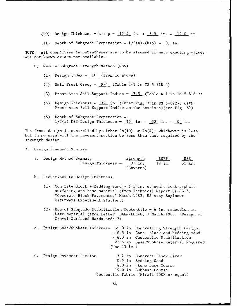
(10) Design Thickness = b + p = 15.5 in. + 3.5 in. = 19.0 in.
(11) Depth of Subgrade Preparation = i/2(a)-(b+p) - 0 in.
NOTE: All quantities in parentheses are to be assumed if more exacting valuesare not known or are not available.
b. Reduce Subgrade Strength Method (RSS)
(1) Design Index = 10 (from lc above)
(2) Soil Frost Group = F-4 (Table 2-1 in TM 5-818-2)
(3) Frost Area Soil Support Indice = 3.5 (Table 4-1 in TM 5-818-2)
(4) Design Thickness = 32 in. (Enter Fig. 3 in TM 5-822-5 withFrost Area Soil Support Indice as the abscissa)(see Fig. Bl)
(5) Depth of Subgrade Preparation =l/2(a)-RSS Design Thickness = 15 in. - 32 in. = 0 in.
The frost design is controlled by either 2a(10) or 2b(4), whichever is less,but in no case will the pavement section be less than that required by thestrength design.
3. Design Pavement Summary
a. Design Method Summary Strength LSFP RSSDesign Thickness = 35 in. 19 in. 32 in.
(Governs)
b. Reductions to Design Thickness
(1) Concrete Block + Bedding Sand = 6.5 in. of equivalent asphaltsurfacing and base material (from Technical Report GL-83-3,"Concrete Block Pavements," March 1983, US Army EngineerWaterways Experiment Station.)
(2) Use of Subgrade Stabilization Geotextile = 6 in. reduction inbase material (from Letter, DAEN-ECE-G, 7 March 1985, "Design ofGravel Surfaced Hardstands.")
c. Design Base/Subbase Thickness 35.0 in. Controlling Strength Design- 6.5 in. Conc. Block and bedding sand- 6.0 in. Geotextile Stabilization22.5 in. Base/Subbase Material Required
(Use 23 in.)
d. Design Pavement Section 3.1 in. Concrete Block Paver0.5 in. Bedding Sand4.0 in. Stone Base Course19.0 in. Subbase Course
Geotextile Fabric (Mirafi 600X or equal)
B4

Desivgn -Index-- 10
GBR Thickness CBR -Thickness
50 4 in. 8 18.5 in.
30 6.5 in. 6 22.5 in.
20 9 in. 4 29.5 in.
15 11.5 in. 3.5 32.0 in.
10 15.5 in. 3 35.0 in.
-50 ----- -=
40
302 ~ ~ ~ ~~~ --------- 0IS 2030 40 5
w 10R
Fiur --. Thckes-eig-rqirmnt-(iur-- foTM---------8-7 C ap 3
---B-- -

ro--' 1
LLJ 0p
0] 4t K I 4 I
ft-- I LtI Z,
A. ,1 T , i ; "w'
,,'. .t,,,
wH
zz
3 Z
igr B2 G ncrt blc I veo ; I o d I I IvdonIIte

Concrete Block Pavements - Installation Notes
1. Prior to starting all required excavations, remove any surface soil from
the existing gravel road by backblading and sweeping. Remove and stockpile
existing gravel road material separately from required soil subgrade
excavation material. Reuse satisfactory stockpiled gravel road material for
subbase course material in accordance with Specification Section 02241A.
Subbase material will be required in addition to this stockpiled gravel road
material. Required additional subbase material shall be obtained from off
post borrow sources at the expense and responsibility of the contractor.
2. Refer to subgrade stabilization detail in Figure B2. Additional materialand placement requirements for subgrade, subgrade stabilization fabric, and
base and subbase are specified in Specification Sections 02230 and 02241A,
respectively.
3. Install concrete curb edge restraint prior to placement of sand beddingcourse and concrete block paver units. The finished elevation of the concrete
curb shall be set 1/4 in. below the top of the adjacent concrete blocks. Cutconcrete blocks shall be used adjacent to the edge restraint as required to
maintain the 1/8-in, joint. Filler fabric (Mirafi 140 or equal) shall beinstalled across all curb joints adjacent to jointing and bedding sand.Fabric shall overlap the joints by 6 in. (minimum) and extend 6 in. (minimum)
below the bottom of the sand bedding course. Additional material and
placement requirements for filter fabric and jointing and bedding sand are
specified in Specification Sections 02241A and 02518, respectively.
4. Place and screed bedding sand to a depth of 1 in. ± 1/4 in. Do not
compact or disturb sand prior to placement of concrete block paver units.Additional material and placement requirements for jointing and bedding sand
are specified in Appendix C.
5. Brown rectangular concrete block paver units (3.1 by 3-7/8 by 7-7/8 in.)
shall be hand placed in a herringbone pattern with blocks laid at a 45 deg
angle to the edge restraints (refer to the illustrated herringbone pattern
detail). Blocks shall be cast with a minimum of one 2-mm long vertical rib
per side to assist in maintaining the 3-mm (1/8-in.) joint between blocks.
Additional material and placement requirements for concrete block paver units
are specified in Appendix C.
B7

Z
-j
EDl/ W
V)I
4 .
4<
- -, 100
0 )
0 I-Ix 2
94 !-I0 M ~I~L
Z ZoY 0
o <,
.1 m
D D
2~ ccn00
I~x40
J- 0
Figure B3. Subgrade stabilization detail
B8

APPENDIX C: CONCRETE BLOCK PAVEMENT GUIDE SPECIFICATION

(September 1989)
DEPARTMENT OF THE ARMY CEGS-02518 (September 1989)U.S. ARMY CORPS OF ENGINEERS
GUIDE SPECIFICATION FOR MILITARY CONSTRUCTION
SECTION 02518
CONCRETE BLOCK PAVEMENTS9/89
NOTE: This guide specification covers therequirements for constructing a concrete blockpavement. This guide specification is to be
used in the preparation of project specificationsin accordance with ER 1110-345-720.
************* **** *** **** ***** ***** **** ** ****** *********** *****
PART 1 GENERAL
NOTE: See Additional Note A.
1.1 SUMMARY (Not Applicable)
NOTE: Paragraph "1.1 ZUMMARY (Not Applicable)"is required in all CEGS in order to make CEGScompatible with guide specifications of otheragencies within the SPECSINTACT System.
However, this paragraph is not to be included inCorps of Engineers project specifications.
1.2 REFERENCES
NOTE: Issue (date) of references included in
project specifications need not be more current
than provided by the latest change (Notice) to
this guide specification.
The publications listed below form a part of this specification to the
extent referenced. The publications are referred to in the text by basicdesignation only.
C3

(September 1989)
AMERICAN CONCRETE INSTITUTE (ACI)
-ACI 301- (1984) Structural Concrete forBuilding
AMERICAN SOCIETY FOR TESTING AND MATERIALS (ASTM)
-ASTM C 33- (1982) Concrete Aggregates
-ASTM C 67- (1987) Sampling and Testing Brickand Structural Clay Tile
-ASTM C 117- (1987) Materials Finer than 75-u=(No. 200) Sieve in Mineral Aggregatesby Washing
-ASTM C 131- (1981; R 1987) Small-size CoarseAggregate by Abrasion and Impact in theLos Angeles Machine
-ASTM C 136- (1984; Rev. a) Sieve Analysis ofFine and Coarse Aggregates
-ASTM C 936- (1982) Solid Concrete InterlockingPaving Units
-ASTM C 979- (1982; R 1986) Pigments forIntegr:-.ly Colored Concrete
-ASTM D 75- (1987) Sampling Aggregates
-ASTM D 1760- (1983) Pressure Treatment ofTimber Products
-ASTM D 4318- (1984) Liquid Limit, PlasticLimit, and Plasticity Index of Soils
-ASTM E 11- (1987) Wire-Cloth Sieves forTesting Purposes
1.3 SUBMITTALS
NOTE: Submittals must be limited to thosenecessary for adequate quality control. Theimportance of an item in the project should beone of the primary factors in determining if asubmittal for the item should be required.
C4
! i I mi

(September 1989)
The following shall be submitted in accordance with Section \=01300=\
"SUBMITTALS":
*SD-50, Samples*
The Contractor shall provide samples of paving blocks and the bedding and
jointing sands in the quantities required under paragraph "TESTS,INSPECTIONS, AND VERIFICATIONS" and at times as directed by theContracting Officer.
*SD-70, Test Reports*
The Contractor shall provide a written report within 7 calendar daysafter completion of the work to the Contracting Officer covering the
testing -equired under paragraph "TESTS, INSPECTIONS AND VERIFICATIONS,"for each lot.
1.4 PAYMENT
NOTE: Delete this paragraph in fixed pricecontracts.
1.4.1 General
Payments will constitute full compensation for all labor, equipment,tools, supplies, and incidentals necessary to complete the work.
1.4.2 Pavements
The blocks, cut blocks, bedding sand, and jointing sand will be paid persquare foot of satisfactorily installed block pavement surface.
1.4.3 Edge Restraint
The edge restraint will be paid per lineal foot of satisfactorilyinstalled edge restraint.
1.5 MAINTENANCE
NOTE: This paragraph will be included only ifthe project has aesthetic considerations wherefuture maintenance must exactly match the color
of the block.
At the completion of work the Contractor shall provide [_] paving
blocks matching those used in the project. These paving blocks will be
delivered stacked on pallets.
C5

(September 1989)
PART 2 PRODUCTS
2.1 MATERIALS
2.1.1 Bedding and Jointing Sand
NOTE: See Additional Note B.
Two separate sand gradations shall be used for the bedding layer and inthe block joints. Both sand gradations will consist of crushed sand,natural sand, or a combination of crushed and natural sand. Both sandgradations shall have a minimum L.A. Abrasion of 40 percent when testedin accordance with ASTM C 131. Both sand gradations shall be nonplasticwhen tested in accordance with ASTM D 4318 and shall be free of lumps,clay, vegel tion, soft particles, sulphates, and other contaminants. Thebedding and jointing sands shall conform to the following gradations,determined in accordance with ASTM C 136 and C 117.
Percent Passine
Sieve (ASTM E-11) Bedding Sand Jointinz Sand
3/8 in. 100 100No. 4 80-100 100No. 8 60-90 95-100No. 16 25-70 70-100No. 30 10-35 40-75No. 50 5-20 10-40No. 100 0-10 2-25No. 200 0-5 0-10
2.1.2 Concrete Paving Block
NOTE: Color and shape of block may bespecified. Check local availability of specificcolors or shapes before specifying. Organicpigments should not be used, since they areunstable in the alkaline concrete environmentand subject to weathering. Shape is generallyrectangular or interlocking.
The concrete paving block shall conform to ASTM C 936, and shall beI[ I thick, [ I in color, and [ ] in shape. Color shallconform to ASTM C 979.
C6

(September 1989)
2.1.3 Edge Restraint
2.1.3.1 Treated Wood
NOTE: Treated wood edge restraint is onlyacceptable for walkways and residentialdriveways. If treated wood is selected for edgerestraint, then ASTM D 1760 (1983) "StandardSpecification for Pressure Treatment of TimberProducts" should be added. Delete thisparagraph when this option is not retained.
The edge restraint shall be wood treated in accordance with ASTM D 1760
and of dimensions shown on the plans.
2.1.3.2 Precast Concrete
NOTE: Minimum compressive strength of precastconcrete should be 3,000 pounds per square inchunless analysis requires some other value.Entrained air content should be 6 percent± 1-1/2 percent in areas where freezing andthawing coverage is a design consideration.Delete this paragraph when this option is notretained.
The edge restraint shall be precast portland cement concrete elementswith the dimensions shown on the plans. The precast concrete shall havea compressive strength of not less than [ ] at 28 days and an
entrained air content of not less than [_ ].
2.1.3.3 Cast-in-Place Concrete
NOTE: Minimum compressive strength of
cast-in-place concrete should be 3,000 poundsper square inch unless analysis requires some
other value. Entrained air content should be
6 percent ± 1-1/2 percent in areas where
freezing and thawing coverage is a design
consideration. Delete this paragraph when this
option is not retained.
The edge restraint shall be portland cement concrete placed with the
dimensions shown in the plans. Concrete shall have a compressivestrength of not less than [_] at 28 days and an entrained air content
C7

(September 1989)
of not less than [ ]. Concrete shall conform with the requirementsof ACI 301.
2.2 TESTS, INSPECTIONS AND VERIFICATIONS
2.2.1 Concrete Paving Block
NOTE: See Additional Note C.
The Contractor shall provide a sample of five paving blocks prior to thestart of the work for the Contracting Officer's approval of the color andshape to be used in the project. Also, the Contractor shall collect arepresentative sample of not less than 15 blocks as directed by theContracting Officer, from each lot of 20,000 concrete paving blocks orfraction thereof. Two paving blocks from each sample will be deliveredto the Contracting Officer. The Contractor shall conduct the testsprescribed by ASTM C 936 and the following tests under the guidance ofthe Contracting Officer on the remaining 13 blocks of each sample fromeach lot.
2.2.1.1 Freezing and Thawing
NOTE: The freezing and thawing test may bewaived for jobs of less than 10,000 square feetor for climates not subject to freezing andthawing.
Resistance to freezing and thawing will be determined in accordance withSection 8 of ASTM C 67 for five blocks. The blocks shall have nobreakage and no more than 1.0 percent loss of any individual unit in dr:weight when subjected to 50 cycles of freezing and thawing.
2.2.1.2 Dimensional Tolerance
The length and width of each block in the sample will not vary from anyother block in this or any other lot sample by more than 1/8 inch.Thickness of any block in the sample will not vary by more than 1/8 inchfrom the specified block thickness.
2.2.1.3 Retest
The Contractor will notify the Contracting Officer if any blocks fail to
meet the specified requirements. In case the shipment fails to conformto the specified requirements, the Contractor may sort it, and newspecimens shall be selected by the Contractor from the retained lot forretesting, as directed by the Contracting Officer. All concrete pavingblock retests shall be performed at the expense of the Contractor. In
C8

(September 1989)
case the second set of specimens fail to conform to the testrequirements, the entire lot shall be rejected.
2.2.2 Sand
2.2.2.1 Sample
The Contractor shall obtain a representative sample in accordance withASTM D 75 from each 100 cubic yard of sand to be used in the project.
2.2.2.2 Gradation
The Contractor shall determine the gradation of the sand in accordancewith the requirements of paragraph "MATERIALS".
2.2.2.3 Test Results and Retest
If the sand fails to meet the requirements of paragraph "MATERIALS", theContractor may take another sample and retest it at his expense. If thisretest fails or if no second test is taken, the sand is rejected by theGovernment and shall be removed from the job site.
PART 3 EXECUTION
NOTE: See Additional Note D.
3.1 PREPARATION
3.1.1 Edge Restraint
The edge restraint shall be placed as shown in the drawings and will beinstalled prior to placement of the blocks.
3.1.2 Sand Bedding Layer
The bedding sand shall be spread evenly over the area to be paved andshall be screeded to an uncompacted average thickness of 1-1/4 inch witha tolerance of ± 1/4 inches. This bedding sand will not be used to filllow areas in the base. The sand shall be left uncompacted and will notbe disturbed by any pedestrian or vehicle construction traffic.
3.2 BLOCK PLACEMENT
NOTE: Paving block to be subject to vehiculartraffic should be placed in herringbone pattern,and this pattern can be specified here.
C9

(September 1989)
The paving block shall be placed by hand or machine in the indicatedpattern. Placement of paving block will start from a corner or straightedge and proceed forward over the undisturbed sand bedding layer. Thejoints excluding any chamfer between paving blocks shall be not less than1/16 inch or more than 1/4 inch in width. The paving blocks will beplaced so that after seating as described in paragraph 3.2.2 the blocksurface will be flush or up to 1/4 inch above the edge restraint.
3.2.1 Unfilled Gaps
Any gaps between paving blocks and any edge restraint, drainagestructures, or other members that cannot be filled with a whole blockwill be filled with a paving block cut to fit the gap. Cutting will bedone with a hydraulic splitter, a masonry saw, or other device that willaccurately leave a clean, vertical face without spalling. Any gapbetween the block and adjoining edge restraint or structure greater than1/4 inch shall be rejected.
3.2.2 Seating Blocks
The blocks shall be seated in the bedding sand by compacting them with aminimum of three passes of a vibratory plate compactor.
3.2.3 Jointing Sand
The Jointing sand shall be swept into joints and vibrated with avibratory plate or vibratory roller compactor. This process willbe continued until sweeping and vibrating have filled all joints withsand and further vibration cannot force additional sand into the joints.The coarser particles of the sand will not enter the joints and will
remain on the surface. These particle- and any excess sand will be sweptoff the pavement.
3.2.4 Timing of Operations
Seating of blocks and placement of jointing sand can be done concurrentlywith block placement. However, seating of blocks and placement ofjointing sand will not be done within 5 feet of any unfinished edge ofthe block pavement that is not supported by the edge restraint.
3.2.5 Final Rolling
NOTE: This paragraph can be deleted for lightload pavements such as driveways or pedestrianwalkways.
The final finished paving block surface will be rolled with four passesof a vibratory or pneumatic roller with a static weight of not less than10,000 pounds.
CI0

(September 1989)
3.2.6 Construction Traffic
Construction traffic shall not be allowed on the paving block surfaceuntil the jointing sand has been placed and vibrated into the joints.
3.3 CLEANUP
The Contractor shall sweep the entire pavement surface and remove allexcess sand, blocks and debris from the project area.
3.4 SMOOTHNESS AND GRADE TOLERANCES
3.4.1 Smoothness
No portion of the finished pavement surface will deviate by more than3/8 inch from a 10-foot-long metal straightedge placed on the pavementsurface.
3.4.2 Block Height
The finished block surface will be either flush or up to 1/4 inch higherthan all edge restraints or drainage structures.
3.4.3 Grade
The finished pavement will be within 0.04 feet of planned grade shown onthe plans.
3.4.4 Remedial Action
Any area not meeting the smoothness, block height, or grade tolerancewill be taken up, adjustments made, and the blocks relaid.
ADDITIONAL NOTES
NOTE A: For additional information on the useof all CEGS, see CEGS-00000 "CEGS GeneralNotes."
NOTE B: If the pavement is to be subjected toDesign Index traffic of 8 or higher, both thebedding and jointing sands shall consist of100 percent crushed sand if it is available inthe construction locale. For block pavements tobe used for walkway, driveway, storage area,parking area, or subject to traffic DesignIndexes of I or 2, the bedding sand gradationcan be changed to the fine aggregate gradationin ASTM C 33 with the additional requirement of0-10 percent passing the No. 200 sieve.
CIlI

(September 1989)
NOTE C: Sampling of paving blocks prior to thestart of the work for the purposes of verifyingthe color and shape of the blocks will only berequired when these considerations are criticalto the project aesthetics. For jobs of lessthan 10,000 square feet or for pavements not tobe exposed to vehicular traffic, a manufacturer'scertificate which certifies that the pavingblocks meet the requirements of ASTM C 936 canbe accepted in lieu of sampling and testing theblocks of each lot.
NOTE D: The base course for the block pavementmust be a dense graded or bound material toavoid loss of the sands from the bedding layer.It must also be properly graded and leveled. Asmoothness of no more than 3/8 inch deviationfrom a 10-foot straight edge is needed. Theproject specification for the pavement basecourse should be checked to ensure theserequirements are met.
-- End of Section --
C12