Embed Size (px)
Citation preview

ContentsContents
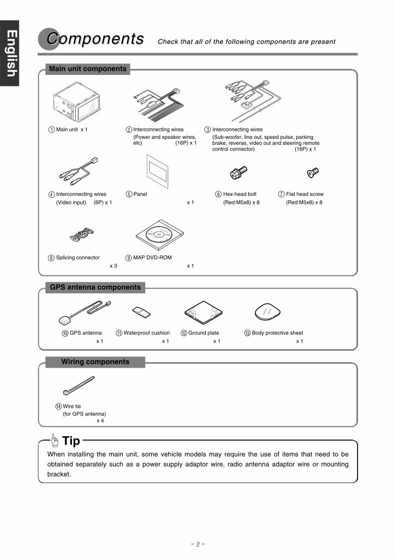
Components
Installation Diagram
Beforeinstallation
Installation
Connections
2For your safety in using the AVN52D 3
5
Names and functions of terminals 6
Installing the GPS antennaInstalling the main unit
1316
DVD Navigation System with 7" Wide TFT Display and DVD Multi-Source Receiver
INSTALLATION MANUAL
Connecting the vehicle speed pulse, parking brake, and reverse wires 10System connection example 12
MODEL
Esp
año
lF
rançais
Italiano
Nederlands
Sven
skaE
ng
lish
Be sure to read this installation manual thoroughly prior to installation. If installation methods or
nonstandard parts not specified in this installation manual are used, accidents or injury may result.
Professional installation is required to install this system. Eclipse recommends you to have the system
installed at your retailer. Be sure to keep this manual after installation for later reference.
Customer should keep manual for reference.
- 2 -
ComponentsComponents Check that all of the following components are present Check that all of the following components are present
GPS antenna components
GPS antenna
x 1
10 Waterproof cushion
x 1
11 Ground plate
x 1
12 Body protective sheet
x 1
13
When installing the main unit, some vehicle models may require the use of items that need to be
obtained separately such as a power supply adaptor wire, radio antenna adaptor wire or mounting
bracket.
Tip
Main unit components
Wiring components
Wire tie(for GPS antenna)
x 4
14
Flat head screw
(Red:M5x8) x 8
7Panel
x 1
5 Hex-head bolt
(Red:M5x8) x 8
6
Splicing connector
x 3
8 MAP DVD-ROM
x 1
9
Main unit x 11 Interconnecting wires(Power and speaker wires,etc) (16P) x 1
2 Interconnecting wires(Sub-woofer, line out, speed pulse, parkingbrake, reverse, video out and steering remotecontrol connector) (16P) x 1
3
En
glish
Esp
año
lF
rançais
Italiano
Nederlands
Sven
skaE
ng
lish
Interconnecting wires
(Video input) (6P) x 1
4
- 3 -
Warnings and caution signs, illustrated below, are posted throughout this manual as well as on the AVN52D.
They show safe and correct ways to handle the main unit to prevent personal injury to you and others and
avoid damage to property.
Before reading through the manual, take time to read through and learn the important information listed in
this section.
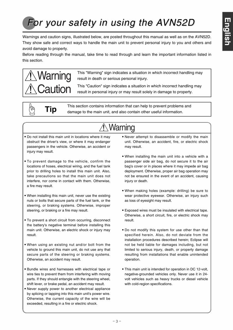
This "Warning" sign indicates a situation in which incorrect handling may
result in death or serious personal injury.
This "Caution" sign indicates a situation in which incorrect handling may
result in personal injury or may result solely in damage to property.
FFor yor your safour safety in using the Aety in using the AVN52DVN52D
This section contains information that can help to prevent problems and
damage to the main unit, and also contain other useful information.Tip
•• Never attempt to disassemble or modify the mainunit. Otherwise, an accident, fire, or electric shockmay result.
•• When installing the main unit into a vehicle with apassenger side air bag, do not secure it to the airbag's cover or in places where it may impede air bagdeployment. Otherwise, proper air bag operation maynot be ensured in the event of an accident, causinginjury or death.
•• When making holes (example: drilling) be sure towear protective eyewear. Otherwise, an injury suchas loss of eyesight may result.
•• Exposed wires must be insulated with electrical tape.Otherwise, a short circuit, fire, or electric shock mayresult.
•• Do not modify this system for use other than thatspecified herein. Also, do not deviate from theinstallation procedures described herein; Eclipse willnot be held liable for damages including, but notlimited to serious injury, death, or property damageresulting from installations that enable unintendedoperation.
•• This main unit is intended for operation in DC 12-volt,negative-grounded vehicles only. Never use it in 24-volt vehicles such as heavy trucks or diesel vehiclewith cold-region specifications.
•• Do not install this main unit in locations where it mayobstruct the driver's view, or where it may endangerpassengers in the vehicle. Otherwise, an accident orinjury may result.
•• To prevent damage to the vehicle, confirm thelocations of hoses, electrical wiring, and the fuel tankprior to drilling holes to install this main unit. Also,take precautions so that the main unit does notinterfere, nor come in contact with them. Otherwise,a fire may result.
•• When installing this main unit, never use the existingnuts or bolts that secure parts of the fuel tank, or thesteering, or braking systems. Otherwise, impropersteering, or braking or a fire may result.
•• To prevent a short circuit from occurring, disconnectthe battery's negative terminal before installing thismain unit. Otherwise, an electric shock or injury mayresult.
•• When using an existing nut and/or bolt from thevehicle to ground this main unit, do not use any thatsecure parts of the steering or braking systems.Otherwise, an accident may result.
•• Bundle wires and harnesses with electrical tape orwire ties to prevent them from interfering with movingparts. If they should entangle with the steering wheel,shift lever, or brake pedal, an accident may result.
•• Never supply power to another electrical applianceby splicing or tapping into this main unit's power wire.Otherwise, the current capacity of the wire will beexceeded, resulting in a fire or electric shock.
Esp
año
lF
rançais
Italiano
Nederlands
Sven
skaE
ng
lish

- 4 -
•• This main unit must be operated only as on-boardmain unit, or it may cause electrical shock or injury.
•• Do not play distorted sounds for long periods of time;the speakers may overheat and cause a fire.
•• Once installation and wiring have been completed,return the brakes and electrical equipment such aslights, horn, hazard warning lights and turn signallights to their original places, and check that theyoperate correctly. If you use the vehicle while any ofthis equipment is not working correctly, fire, electricshocks or accidents may occur.
•• Use supplied wire harness with this main unit. Othermanufacturers may use a similar wire harnessconnector but pin configurations are incorrect for usewith Eclipse main units and can damage the mainunit. Prior to powering up the main unit, please makesure the main unit is properly grounded with thevehicle chassis. If no ground is available to thechassis, add a ground strap from the main unit to thevehicle chassis to improve the ground.
•• Do not use with speakers having 1 to 3 ohmsimpedance. This main unit is designed to be usedwith high-powered speakers rated above 50 W withimpedance rating between 4 and 8 ohms.
•• For best results, this main unit should be installed bya professional installer. Contact the dealer whom you purchased the mainunit for an appointment.
•• When installing this main unit, be sure to use thesupplied mounting hardware. If parts other thanthose supplied are used, the main unit may bedamaged internally, or may not be held in placesecurely and become dislodged.
•• Avoid installing this main unit in places where it mayget wet, such as near windows, or in places that aremoist or dusty. Presence of liquid, moisture, or dustinside this main unit can cause short circuitingresulting in smoke or fire.
•• If this main unit is not connected properly, a shortcircuit, fire, or accident may occur.
•• When routing wires, use precautions to preventcontact of sharp metal parts such as brackets orscrew tips. Otherwise, a short circuit, electric shock,fire, or accident may result.
•• Play the audio at a moderate volume level thatpermits you to hear sounds from outside the vehicle.Driving without being able to hear outside soundsmay result in an accident.
•• Do not operate the main unit in a malfunctioningcondition, for instance, when the audio does not play.Doing so may result in an accident, fire, or electricalshock.
•• If an abnormal situation occurs, such as foreignmatter entering or liquid splashing on the main unit,or smoke or a strange odor emitting from the mainunit, shut off the main unit immediately and consultthe dealer from whom you purchased it. Continuedoperation may cause an accident, fire, or electricalshock.
•• Do not place the vinyl storage bag over a person'shead. It may cause a serious accident or death bysuffocation.
•• Do not disassemble or rebuild this main unit. Doingso may cause an accident, fire, or electrical shock.
•• When it is necessary to replace the fuse, always usea fuse of the correct rating (number of amperes). Useof fuses with higher amperage ratings may cause afire.
En
glish
Esp
año
lF
rançais
Italiano
Nederlands
Sven
skaE
ng
lish

- 5 -
Installation DiagInstallation Diagrramam
GPS antenna
(When installing inside the vehicle)
10
GPS antenna
(When installing outside the vehicle)
10
•• If installing the GPS antenna inside the vehicle, the location and the slope of the vehicle's windshieldwill determine the accuracy of the GPS antenna to receive the GPS signal. If the GPS antennalocation inside the vehicle is hindering the accuracy of the GPS antenna, then you may want to installthe antenna outside of the vehicle.
•• The materials used in front and rear vehicle windows can cause GPS reception sensitivity to dropsignificantly. If this happens, install the GPS antenna on the outside of the vehicle.
Tip
Tip
Main unit1
Esp
año
lF
rançais
Italiano
Nederlands
Sven
skaE
ng
lish
- 6 -
•• Never cut the insulation on the power wire or use it to power any other equipment. If the rated current capacity of the power wire
is exceeded, fire and electric shocks may result.
•• The wires should be secured with tape or a similar securing method to prevent any obstructions while driving. If they get wound
or entangled around components such as the steering wheel, shifting lever, or brake pedal, accidents may result.
•• If removing the end of the wire to connect to another wire, be sure to wrap PVC tape or a similar wire insulating method around
the connection to insulate it. If the connection is not insulated, fire or accidents may result.
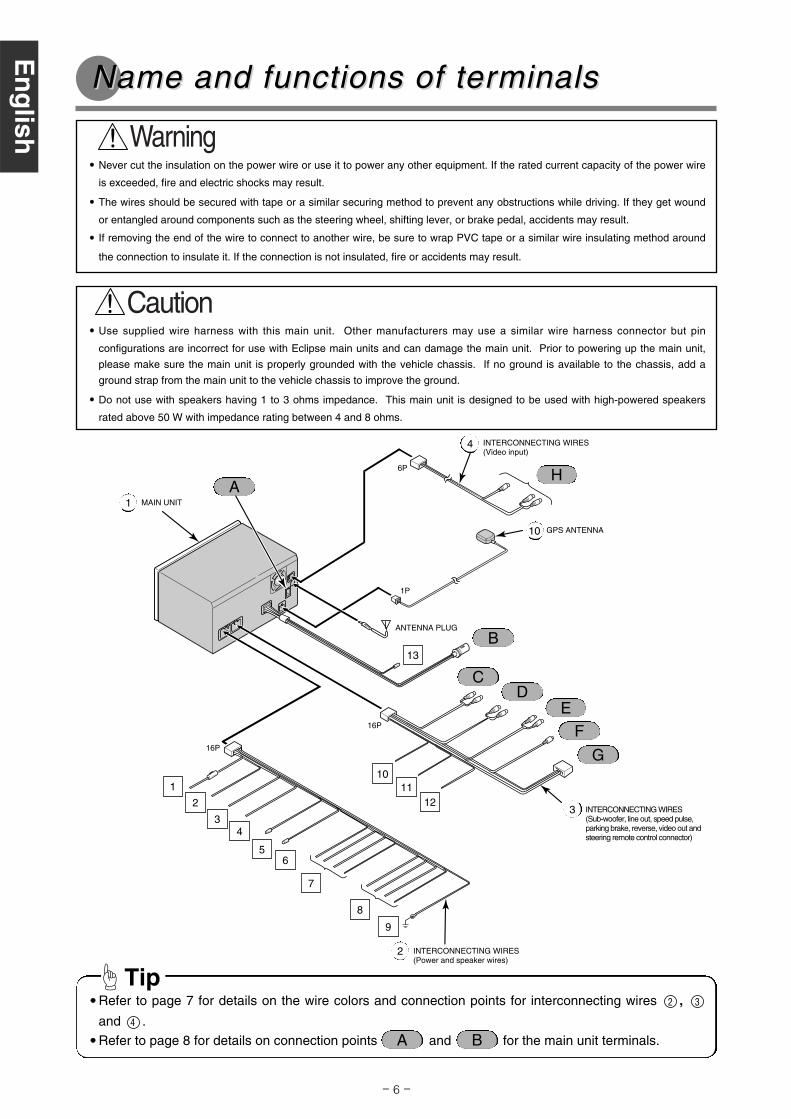
Name and functions of terName and functions of terminalsminals
1
2
34
5
GPS ANTENNA10
13
16P
B
6
7
9
1011
12
H
F
ED
C
A
ANTENNA PLUG
MAIN UNIT1
INTERCONNECTING WIRES(Sub-woofer, line out, speed pulse,parking brake, reverse, video out andsteering remote control connector)
3
INTERCONNECTING WIRES(Power and speaker wires)
2
G
•• Refer to page 7 for details on the wire colors and connection points for interconnecting wires ,
and .
•• Refer to page 8 for details on connection points and for the main unit terminals.4
32
Tip
B
•• Use supplied wire harness with this main unit. Other manufacturers may use a similar wire harness connector but pin
configurations are incorrect for use with Eclipse main units and can damage the main unit. Prior to powering up the main unit,
please make sure the main unit is properly grounded with the vehicle chassis. If no ground is available to the chassis, add a
ground strap from the main unit to the vehicle chassis to improve the ground.
•• Do not use with speakers having 1 to 3 ohms impedance. This main unit is designed to be used with high-powered speakers
rated above 50 W with impedance rating between 4 and 8 ohms.
8
En
glish
Esp
año
lF
rançais
Italiano
Nederlands
Sven
skaE
ng
lish
6P
1P
INTERCONNECTING WIRES(Video input)
4
A
16P

- 7 -
Wire colors and connection points for connection wires , and 432
Never connect the power supply to the speaker wires (No.7 and No.8),
otherwise it will cause damage to the main unit.Caution
B+ (Yellow)Connect where power is constantly available, regardless of the ignition key's position.
ACC (Red)Connect where the power comes on when the ignition is in the ACC position.
Illumination power supply (Orange/White)Connect to where power comes on when the vehicle light switch is turned on.
Cellular phone mute wire (Pink)If you use a cellular telephone, connect it via the Audio Mute lead on the cellular telephone.
If not, keep the Audio Mute lead free of any connections.
Antenna power supply (Blue)Connect to the automatic-antenna control terminal of the vehicle.
Control power supply (Blue/White)Connect to the control terminal for the external amplifier, etc.
Front speaker output wiresConnect to the front speakers. White: Left + White/Black: Left -
Gray: Right + Gray/Black: Right -
Rear speaker output wiresConnect to the rear speakers. Green: Left + Green/Black: Left -
Purple: Right + Purple/Black: Right -
Ground (Black)Connect where good body grounding is available.
Vehicle speed pulse signal wire (Purple/White)
Connect to the vehicle speed pulse signal terminal.
Parking brake signal wire (Red/White)Connect to the parking brake signal terminal.
Reverse signal wire (Green)
Connect the reverse signal output of the vehicle to this terminal.
Front line-out terminalsConnect to the RCA connector of an external amplifier.
Rear line-out terminalsConnect to the RCA connector of an external amplifier.
Line-out terminals (Sub-woofer)This is used for non fader output. It can be used as a sub-woofer terminal if a separate amplifier with
a low bass filter is connected.
12
11
10
9
8
7
6
5
4
3
2
1
Esp
año
lF
rançais
Italiano
Nederlands
Sven
skaE
ng
lish
D
E
C
- 8 -
En
glish
Esp
año
lF
rançais
Italiano
Nederlands
Sven
skaE
ng
lish
VTR output terminalsConnect to the monitor with video input.
Genuine steering remote control terminalConnect to the vehicle steering remote control.
※Compatible vehicle models for installation : Vehicles with voltage detection-type steering remote control.Ask your dealer for details.
VTR input terminalsConnect to the output wire of external video main unit such as a VTR.
Yellow : Video signal White : Audio (left) signal Red : Audio (right) signal
G
H
Main unit connections
ACC ON/OFF power supply terminal (blue/white)If you use this terminal to connect main unit such as an external amplifier, you can still hear the audio guidance
from the navigation system even when audio is turned off. Connect it to the control terminal for the external
amplifier or other main unit.
※ A popping noise may be heard when the engine is being started or the ignition switch is at the ON position, but
this is normal and is not the sign of a malfunction.
Back-eye camera external input terminal (4P)Used with the Eclipse back-eye camera (sold separately).
E-LAN terminal (13P)Connect to the E-LAN terminal of the CD changer and iPod adapter, etc.
13
A
B
F

- 9 -
Vehicle component adapter wires
Vehicle harness
From main unit
- Example of using vehicle adapter wires -
- Vehicle connections -
Power supplies
for combined
equipment
Esp
año
lF
rançais
Italiano
Nederlands
Sven
skaE
ng
lish•• You will need to purchase the necessary vehicle component adapter wire for the vehicle so that the
power supplies can be utilized. (Contact the dealer for further details.)
•• Be sure to wrap the connection wires with electrical tape or another insulation method to insulate them.
Tip
- 10 -
Notes on installation
•• Check the vehicle speed pulse signal, parking brake signal, and reverse signal carefully before making
the connections. If the wires are incorrectly connected, accidents or problems with correct operation
may result.
•• The label on the vehicle speed pulse signal wire contains a protection circuit, so do not cut the wire or
remove the protective circuit, otherwise problems with operation may result.
•• Bind the wires together with tape so that they do not cause an obstruction while driving. If they become
wound or entangled around parts such as the steering wheel, shifting lever, or brake pedal, accidents
may result.
The locations where vehicle speed pulse signal wire, parking brake signal wire, and reverse wire may
vary depending on the vehicle model and grade. Ask the car dealer or your nearest Eclipse dealer for
details.
Tip
Connecting the vConnecting the vehicle speed pulseehicle speed pulse, par, parkingkingbrbrakakee, and re, and revverse wireserse wires
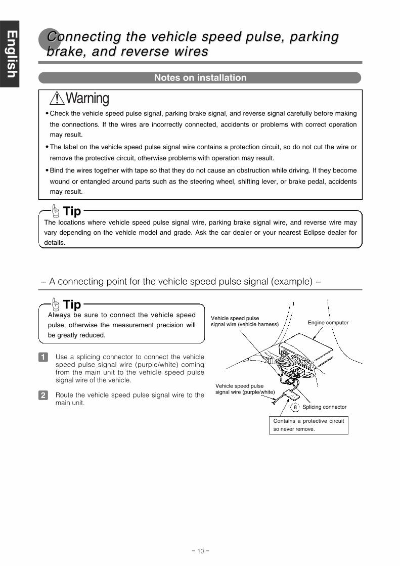
- A Connecting point for the vehicle speed pulse signal (example) -
Vehicle speed pulsesignal wire (vehicle harness) Engine computer
Vehicle speed pulsesignal wire (purple/white)
Contains a protective circuit
so never remove.
Splicing connector
Always be sure to connect the vehicle speed
pulse, otherwise the measurement precision will
be greatly reduced.
Tip
8
Use a splicing connector to connect the vehiclespeed pulse signal wire (purple/white) comingfrom the main unit to the vehicle speed pulsesignal wire of the vehicle.
1
Route the vehicle speed pulse signal wire to themain unit.
2E
ng
lishE
spañ
ol
Fran
çaisItalian
oN
ederlandsS
venska
En
glish

Route the parking brake signal wire to the mainunit.
- 11 -
Foot-operatedparking brake
Hand-operatedparking brake
- A connecting the point for parking brake signal (example) -
Attach a splicingconnector at this location.
Reverse signal wire
Reverse lamp
Reverse signal wire
- A connecting point for the reverse signal (example) -
•• Be sure to connect the reverse signal wire. If it is
not connected, the vehicle position may be
incorrect when the vehicle is reversed.
•• Use a circuit tester to confirm that a sensing voltage
of 6 V or higher is generated when the vehicle is
reversed.
Tip
- Using the splicing connector -
Insert the interconnecting wire [vehicle speedpulse signal wire (purple/white), parking brakesignal wire (red/white), or reverse signal wire(green)] from the main unit and the vehicle wireinto the splicing connector.
1
Push in the terminal (the metal part) of thesplicing connector using a pair of pliers.
2
Harness in the car
Vehicle speed pulse signal wire(purple/white), parking brake wire,(red/white) or reverse wire (green)
Splicing connector8
Press down the cover of the splicing connectorand squeeze it until it locks.
3Lock
Splicing connector8
Use a splicing connector to connect the reversesignal wire (green) coming from the main unit tothe reverse signal wire of the vehicle.
1
Route the reverse signal wire to the main unit .2
Use a splicing connector to connect the parkingbrake signal wire (red/white) coming from themain unit to the parking brake signal wire of thevehicle.
1
2
Parking brakesignal wire
Attach a splicingconnector at this location.
Parking brakesignal wire
Esp
año
lF
rançais
Italiano
Nederlands
Sven
skaE
ng
lish
- 12 -
System connection eSystem connection examplexample
•• Install and connect all of the peripheral units before connecting them to the main unit.•• Do not remove any of the protective caps (RCA, etc.) unless in use.•• Be sure to wrap the connection wires with tape (PVC tape) to insulate them.
Tip
•• Never cut the insulation on the power wire or use it to power any other main unit. If the rated currentcapacity of the power wire is exceeded, fire and electric shocks may result.
•• The wires should be secured with tape or a similar securing method to prevent any obstructions whiledriving. If they get wound or entangled around components such as the steering wheel, shifting lever,or brake pedal, accidents may result.
••If removing the end of the wire to connect to another wire, be sure to wrap PVC tape or a similar wireinsulating method around the connection to insulate it. If the connection is not insulated, fire oraccidents may result.
Black
TO GROUND
Yellow
Yellow
Red
Red/White
Blue
Blue/White
FRONT
SPEAKERS
TO EXTERNAL VIDEO EQUIPMENT
(Remove cap when using external video
equipment)
GPS ANTENNA10MAIN UNIT1 Yellow
White
Red
20P
4P
6P
1P
16P
13P
2P
En
glish
Esp
año
lF
rançais
Italiano
Nederlands
Sven
skaE
ng
lish
TEL MUTE
Green
Orange/White
INTERCONNECTING WIRES(Video input)
4
TO SUB-WOOFER
(Remove caps when using
external Sub-woofer)
FROM EXTERNAL VIDEO EQUIPMENT(Remove caps when using external video equipment)
13P
TO GROUND
POWER
CONNECTOR WIRE
(Supplied with CD changer)REAR
SPEAKERS
Black
Yellow
Pink
DIN WIRE(Supplied with CD changer)
TO BATTERY+12V(Permanent Supply)
TO VEHICLE SPEED PULSE SIGNAL
TERMINAL (Refer to
page 10)
TO PARKING BRAKE SIGNAL
(Refer to page 11)
TO REVERSE SIGNAL
(Refer to page 11)
TO BATTERY+12V
(Permanent Supply)
TO ACC (Power Supply)
TO HEAD LIGHT SWITCH
(Illumination (+))
TO POWER ANTENNA RELAY (Supply)
TO TURN-ON WIRE OF EACH EQUIPMENT (Supply)
FRONT
REAR
(Remove caps when using
external amplifier)
TO STEERING
REMOTE CONTROL
ANTENNA PLUG
BEC106(sold separately)
NO CONNECTION
CH3083(sold separately)
Blue/White
Purple/White
INTERCONNECTING WIRES
(Sub-woofer, line out, sp
eed pulse,
parking brake, re
verse, vid
eo out and
steering remote co
ntrol connecto
r)
3
INTERCONNECTING WIRES(Power and speaker wires)
2
16P

- 13 -
Tip
Installing the GPS antennaInstalling the GPS antenna
Notes on installation
•• Do not install the antenna in places (such as frontpillars and roof panel) that are shielded from the sky.
•• The GPS antenna should be installed in a levelposition where the signals will be as unobstructed asmuch as possible, such as on the vehicle's roof.Satellite signals cannot be received if the antenna isobscured or obstructed.
•• If installing the GPS antenna outside the vehicle,remove the main antenna unit if leaving the vehicleunattended for long periods in order to prevent theftor malicious damage to the antenna.
•• Hold the main antenna unit when removing theantenna. Do not pull on the wire, otherwise it maybecome damaged and result in problems with correctoperation.
•• If installing the GPS antenna outside the vehicle,remove the main antenna unit when washing thevehicle. (If you wash the vehicle with the mainantenna unit still attached, avoid spraying the wiresection directly with water so that no water getsinside the vehicle.)
•• The magnet that is attached to the GPS antenna isextremely strong. Be sure to note the following wheninstalling the antenna.
• Do not put the antenna down on the ground or ondirty or dusty surfaces. If iron filings becomeattached to the magnet, they may cause damageto the vehicle's body.
• Keep the antenna away from watches andmagnetic cards, otherwise they may be damagedand/or rendered unusable.
•• If the vehicle glass is a special type of glass such asheat-reflective glass or bullet-proof glass, be sure toinstall the GPS antenna outside of the vehicle. If theGPS antenna is installed inside of the vehicle, thereception sensitivity will severely drop and will affectthe accuracy of the position measurement.
•• If installing the GPS antenna inside the vehicle, besure it is mounted to the ground plate.
•• If installing the GPS antenna inside the vehicle, thelocation and the slope of the vehicle's windshield willdetermine the accuracy of the GPS antenna toreceive the GPS signal. If the GPS antenna locationinside the vehicle is hindering the accuracy of theGPS antenna, then you may want to install theantenna outside of the vehicle.
•• The materials used in front and rear vehicle windowscan cause GPS reception sensit ivity to dropsignificantly. If this happens, install the GPS antennaon the outside of the vehicle.
•• If the attachment surface is a non-plastic surfacesuch as genuine leather, wood panel, or cloth,attaching the antenna may damage the surfacefinish. Do not attach the ground plate to suchsurfaces.
•• Wipe the installation surface thoroughly so that it isclear of any dirt, moisture, or grease before installingthe antenna.
•• Do not apply any coatings to the GPS antenna,otherwise it may cause a drop in the receptionsensitivity of the antenna.
•• Route the GPS antenna wire as far away as possiblefrom TV and radio antennas, and wires, otherwise, itmay cause interference with video and audio signals.
•• The wires should be bound together with tape or a similar securing method (example: wire ties) so that
they do not interfere with driving. If it becomes wound or entangled around parts such as the steeringwheel, shifting lever, or brake pedal, accidents may result.
•• Do not install the GPS antenna where it will obstruct the driver's vision or where it will be an obstacle
while driving, otherwise traffic accidents may result.
Esp
año
lF
rançais
Italiano
Nederlands
Sven
skaE
ng
lish
- 14 -
- Installation inside the vehicle (example) -
Choose an installation location on the dashboard
which is flat and has a clear view of the sky.1
Install the ground plate to the dashboard.2
Install the GPS antenna to the ground plate.3
Ground plate12
Secure the GPS antenna.4
Route the GPS antenna wire along the crevice
between the front windshield and the dashboard.5
Route the GPS antenna to the main unit 's
installation location.6
GPS antenna10
Front of vehicle
Front of vehicle
Tape
GPS antenna10
GPS antenna wire10
•• Select a location that is at least 20 in. away fromthe main unit. If this is not done, the GPSmeasurement precision will drop.
•• Be sure to use the ground plate when installingthe GPS antenna. If the ground plate is not used,the reception sensitivity will drop and will affectthe accuracy of the position measurement.
Tip
If the GPS antenna wire protrudes from the
dashboard, wind tape around it so that it stays
securely fixed in the crevice between the front
windshield and the dashboard.
Tip
If installing the GPS antenna inside the vehicle, the installation location and the shape of the vehicle's
body will determine GPS accuracy. Accuracy is usually lower when the GPS antenna is installed
inside the vehicle.
Tip
Tip
Tip
En
glish
Esp
año
lF
rançais
Italiano
Nederlands
Sven
skaE
ng
lish
Tape

- 15 -
- Installation outside the vehicle (example) -
Choose an installation location where the GPS
antenna can be attached securely.1
Remove the backing paper from the body
protective sheet and attach the sheet to the
vehicle.
2
Install the GPS antenna on top of the body
protective sheet.3
Body protectivesheet (clear)
13
Route the GPS antenna wire to the main unit
while securing it with tape.7
GPS antenna10
Front of vehicle
Route the GPS antenna wire inside the vehicle's
trunk and secure it with tape.4
Attach the waterproof cushion so that the GPS
antenna wire is flat against the weatherstrip when
the trunk lid is closed.
5
Route the GPS antenna wire while securing it
with wire ties.6
To aid in sliding the waterproof cushion in finding
the desired mounting location, apply plain or
soapy water to the waterproof cushion.
Tip
Wire tie14
Waterproof cushion
Front of vehicle
Weatherstrip
11
Front of vehicle
Route tomain unit
Esp
año
lF
rançais
Italiano
Nederlands
Sven
skaE
ng
lish
Tape
Tape

Remove the pocket and any other accessories
from the center cluster to make room for the main
unit.
1
Remove the mounting brackets for the pocket.2
Attach the brackets to the main unit.3
Install the main unit in the vehicle.4
Be careful not to forcefully push on the main unit'sdisplay or buttons during installation. This mayresult in damage to the main unit.
Tip
Be sure to use the supplied accessory mountingscrews (Red: M5 x 8) as the mounting screws. Ifany other screws are used, they may damage theinside of the main unit.
Tip
- 16 -
Installing the main unitInstalling the main unit
30˚ or less
Level (reference)
Front
- Installation angle -
To maintain proper function, the main unit must be
mounted less than 30 degrees. If the angle is in
excess of 30 degrees, DVD skipping and improper
DVD ejection may occur.
Tip
Mounting bolts
Pocket, etc
Center cluster panel
Main unit
Mounting bracket
Hex-head bolt(Red:M5 x 8) x 8
Hex-head bolt(Red:M5 x 8) x 8
Flatheadscrew(Red:M5x8) x 8
Select the screws in accordance with the shapesof the screw holes in the mounting bracket.
6 7
6
1
- Mounting the main unit -
En
glish
Esp
año
lF
rançais
Italiano
Nederlands
Sven
skaE
ng
lish
••Carefully bind any excess length of wire thatis connected to the main unit and secure itto an area of empty space in the vehicle sothat it does not dislodge or interfere with themain unit or vehicle-side equipment. If thewires are not handled correctly, operatingproblems or short-circuits may occur, andthis may result in the danger of fire or otheraccidents.
••Connect all wires before installing the mainunit.
Tip
"ECLIPSE" is a registered trademark ofFUJITSU TEN LIMITED in 54 countries.