Embed Size (px)
Citation preview
3-2 Optical Inter-orbit Communication Experimentbetween OICETS and ARTEMIS
JONO Takashi
KeywordsOptical Inter-orbit communication, Space optical communication
1 Introduction
Unlike radio wave communications, opti-cal communication systems in space can make their antennas compact. Taking advantage of the wide band characteristics of lasers, light-weight compact communication equipment mounted on a satellite can realize high-speed large-capacity communications. Optical com-munications have therefore attracted attention as next-generation core technologies for space communication networks using satellites. However since the technologies for optical communications, such as high-precision track-ing and pointing technology using laser beams, are quite different from those for optical fiber communications on the ground, they have not yet been put into practical use, although their use has been anticipated.
Research activities in Japan have been per-formed since the 1980s at various research in-stitutes and universities. The National Institute of Information and Communications Technol-ogy (NICT), Advanced Telecommunications Research Institute International (ATR), and Japan Aerospace Exploration Agency (JAXA)
Optical Inter-orbit Communications Engineering Test Satellite (OICETS) is an advanced en-
gineering test satellite developed by Japan Aerospace Exploration Agency (JAXA) with two pur-
poses. One is inter-orbit communication experiment between the OICETS and European Space
Agency’s geostationary satellite ARTEMIS. Another is optical communication experiment with
the NICT optical ground station. Optical inter-orbit communications experiment between
OICETS and ARTEMIS were performed from December, 2005 to August, 2006. This paper de-
scribes overview of the inter-orbit communication experiment system and summary of experi-
ment results.
have conducted trial research [1][2]. In 1994, laser communication equipment (LCE) devel-oped by NICT was mounted on the JAXA en-gineering test satellite Ⅵ and was successfully used for communications between a satellite and the ground for the first time in the world [3][4].
The Optical Inter-orbit Communications Engineering Test Satellite (OICETS) that will be introduced in this article was developed mostly for two purposes. One was to conduct experiments of optical inter-orbit communica-t ions between a low earth orbit and a stationary orbit, using OICETS and stationary satellite ARTEMIS developed by the Europe-an Space Agency (ESA). Another was to per-form experiments of optical communications between low earth orbit and the ground using OICETS and the NICT optical ground station. OICETS was deployed in August 2005 into a sun synchronous orbit of an altitude of about 610 km and an orbital inclination of 97.8°. The satellite was named “Kirari.”
The experiments of optical inter-orbit communications between OICETS and AR-TEMIS were conducted collaboratively by Ja-
23JONO Takashi

pan and Europe in the period from December 2005 to August 2006, and experimental results were obtained for various orbits. This article gives an overview of the experiment system, and reports major experimental results ob-tained in experiments using OICETS and AR-TEMIS.
2 Optical inter-orbit communica-tions experiment system
2.1 Optical inter-orbit communications equipment mounted on satellites
Each of JAXA OICETS and ESA ARTE-MIS have originally-developed optical inter-orbit communications equipment. To conduct communications experiments in orbit, JAXA and ESA jointly created the Space Segment Interface Document (S-ICD) to share commu-nications interface specifications, and each of them developed optical inter-orbit communi-cat ions equipment according to these specifications. S-ICD specifies the wave length, modulation method, intensity, pulse characteristics of optical modulating waves, and sequence of tracking and pointing each other’s laser beams, etc. The major interface rules of S-ICD are shown in Table 1.
The optical inter-orbit communications equipment mounted on the OICETS is called LUCE (Laser Utilizing Communication Equipment) and that on the ARTEMIS is
called OPALE (Optical Payload Laser Experi-ment). The significant functional difference between LUCE and OPALE is the presence/absence of a beacon light transmission unit. Beacon light is used only at the initial stage of the tracking and pointing sequence. A beacon beam of a spread angle of 750 μrad, wider than the spread angle of 6 μrad of communica-tions laser beams, is radiated to the target sat-ellite. By scanning it in a spiral form, impor-tant initial tracking can be secured. For the details of the performance of OPALE, see ref-erences [5] and [6]. In what follows I describe LUCE developed by JAXA.
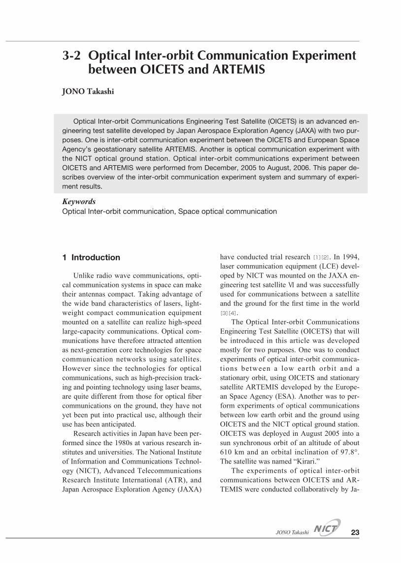
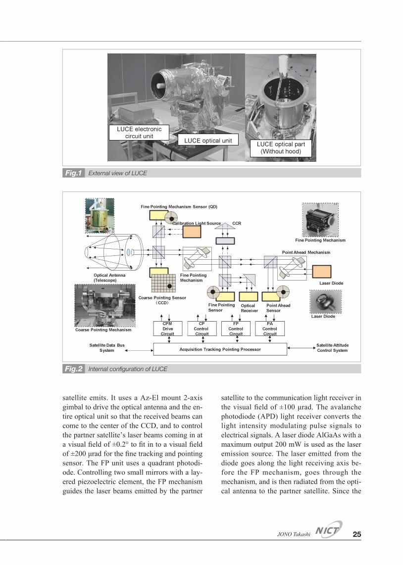
LUCE consists of the LUCE optical unit, which is installed on the outside of the satellite body, and the LUCE electronic circuit unit, which is installed inside the satellite. The ap-pearance of LUCE is shown in Fig. 1 and the internal configuration in Fig. 2. The optical unit consists of an optical antenna with a 26 cm Cassegrain reflecting telescope, a 2-axis gimbal coarse pointing (CP) mechanism unit, and a fine pointing (FP) mechanism unit. The electronic circuit unit consists of a tracking, pointing and directing processor and CP and FP control circuits. The two CP and FP track-ing and pointing units take charge of different parts of the function depending on the control drive range, band width, and precision. The CP unit uses an interline, 2-dimensional CCD to track and point the beams that the partner
Major rules of interface for optical inter-orbit communicationsTable 1
Forward link(OPALE to LUCE)
Return link(LUCE to OPALE)
Wavelength 819nm (communication beam)801nm (beacon beam) 847nm (communication beam)
Polarization LHCP LHCPData rate 2.048M bps 49.3724M bpsModulation IM-DD IM-DDSignal format 2PPM NRZExtinction Ratio < 2% Imin/Imax < 2% Imin/ImaxIntensity Min. 25.2MW/sr
Max. 130MW/srMin. 280MW/srMax. 780MW/sr
Bit error rate < 10–6 < 10–6
24 Journal of the National Institute of Information and Communications Technology Vol. 59 Nos. 1/2 2012
satellite emits. It uses a Az-El mount 2-axis gimbal to drive the optical antenna and the en-tire optical unit so that the received beams can come to the center of the CCD, and to control the partner satellite’s laser beams coming in at a visual field of ±0.2° to fit in to a visual field of ±200 μrad for the fine tracking and pointing sensor. The FP unit uses a quadrant photodi-ode. Controlling two small mirrors with a lay-ered piezoelectric element, the FP mechanism guides the laser beams emitted by the partner
satellite to the communication light receiver in the visual field of ±100 μrad. The avalanche photodiode (APD) light receiver converts the light intensity modulating pulse signals to electrical signals. A laser diode AlGaAs with a maximum output 200 mW is used as the laser emission source. The laser emitted from the diode goes along the light receiving axis be-fore the FP mechanism, goes through the mechanism, and is then radiated from the opti-cal antenna to the partner satellite. Since the
External view of LUCEFig.1
Internal confi guration of LUCEFig.2
25JONO Takashi
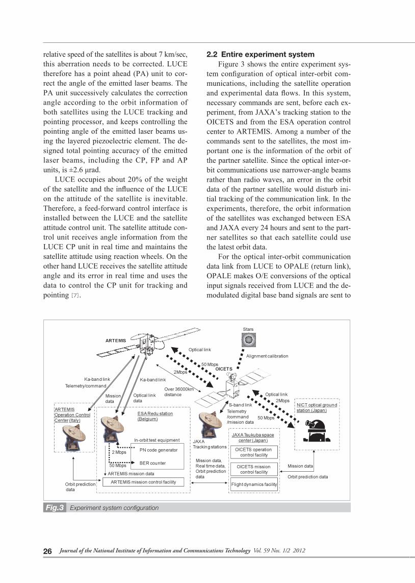
relative speed of the satellites is about 7 km/sec, this aberration needs to be corrected. LUCE therefore has a point ahead (PA) unit to cor-rect the angle of the emitted laser beams. The PA unit successively calculates the correction angle according to the orbit information of both satellites using the LUCE tracking and pointing processor, and keeps controlling the pointing angle of the emitted laser beams us-ing the layered piezoelectric element. The de-signed total pointing accuracy of the emitted laser beams, including the CP, FP and AP units, is ±2.6 μrad.
LUCE occupies about 20% of the weight of the satellite and the influence of the LUCE on the attitude of the satellite is inevitable. Therefore, a feed-forward control interface is installed between the LUCE and the satellite attitude control unit. The satellite attitude con-trol unit receives angle information from the LUCE CP unit in real time and maintains the satellite attitude using reaction wheels. On the other hand LUCE receives the satellite attitude angle and its error in real time and uses the data to control the CP unit for tracking and pointing [7].
2.2 Entire experiment systemFigure 3 shows the entire experiment sys-
tem configuration of optical inter-orbit com-munications, including the satellite operation and experimental data flows. In this system, necessary commands are sent, before each ex-periment, from JAXA’s tracking station to the OICETS and from the ESA operation control center to ARTEMIS. Among a number of the commands sent to the satellites, the most im-portant one is the information of the orbit of the partner satellite. Since the optical inter-or-bit communications use narrower-angle beams rather than radio waves, an error in the orbit data of the partner satellite would disturb ini-tial tracking of the communication link. In the experiments, therefore, the orbit information of the satellites was exchanged between ESA and JAXA every 24 hours and sent to the part-ner satellites so that each satellite could use the latest orbit data.
For the optical inter-orbit communication data link from LUCE to OPALE (return link), OPALE makes O/E conversions of the optical input signals received from LUCE and the de-modulated digital base band signals are sent to
Experiment system confi gurationFig.3
26 Journal of the National Institute of Information and Communications Technology Vol. 59 Nos. 1/2 2012
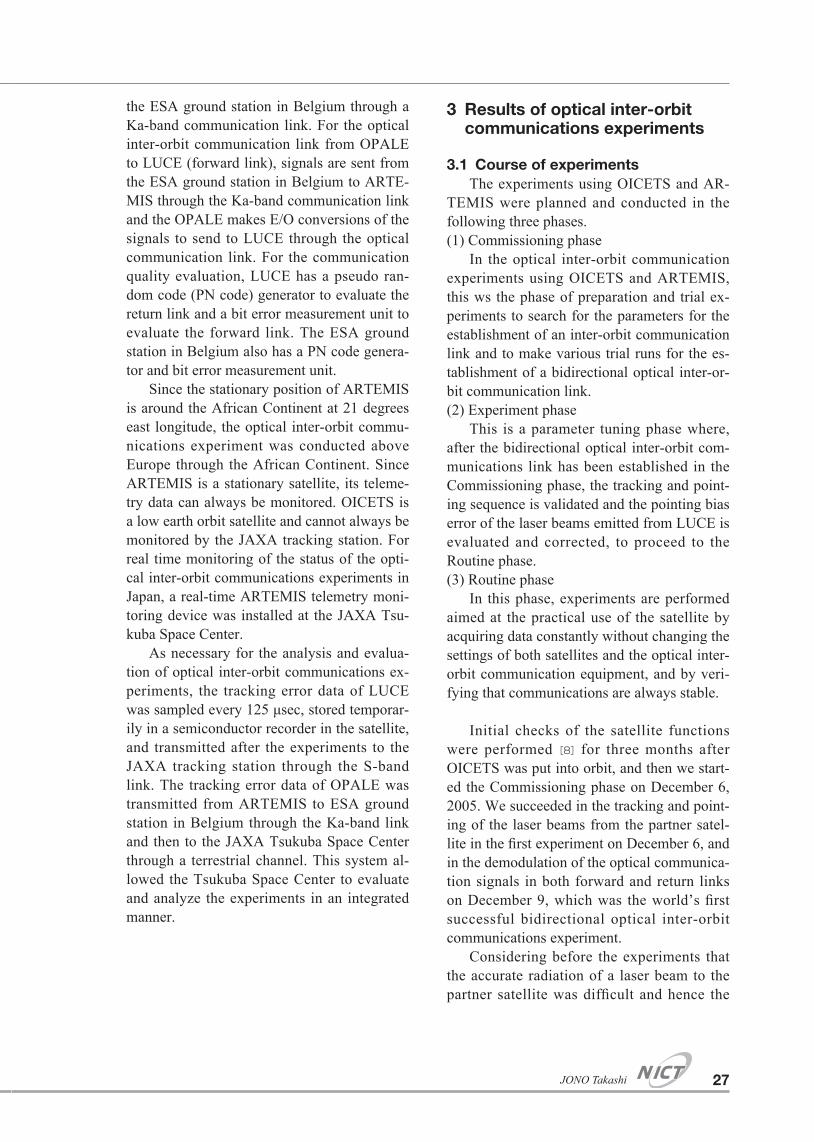
the ESA ground station in Belgium through a Ka-band communication link. For the optical inter-orbit communication link from OPALE to LUCE (forward link), signals are sent from the ESA ground station in Belgium to ARTE-MIS through the Ka-band communication link and the OPALE makes E/O conversions of the signals to send to LUCE through the optical communication link. For the communication quality evaluation, LUCE has a pseudo ran-dom code (PN code) generator to evaluate the return link and a bit error measurement unit to evaluate the forward link. The ESA ground station in Belgium also has a PN code genera-tor and bit error measurement unit.
Since the stationary position of ARTEMIS is around the African Continent at 21 degrees east longitude, the optical inter-orbit commu-nications experiment was conducted above Europe through the African Continent. Since ARTEMIS is a stationary satellite, its teleme-try data can always be monitored. OICETS is a low earth orbit satellite and cannot always be monitored by the JAXA tracking station. For real time monitoring of the status of the opti-cal inter-orbit communications experiments in Japan, a real-time ARTEMIS telemetry moni-toring device was installed at the JAXA Tsu-kuba Space Center.
As necessary for the analysis and evalua-tion of optical inter-orbit communications ex-periments, the tracking error data of LUCE was sampled every 125 μsec, stored temporar-ily in a semiconductor recorder in the satellite, and transmitted after the experiments to the JAXA tracking station through the S-band link. The tracking error data of OPALE was transmitted from ARTEMIS to ESA ground station in Belgium through the Ka-band link and then to the JAXA Tsukuba Space Center through a terrestrial channel. This system al-lowed the Tsukuba Space Center to evaluate and analyze the experiments in an integrated manner.
3 Results of optical inter-orbit communications experiments
3.1 Course of experimentsThe experiments using OICETS and AR-
TEMIS were planned and conducted in the following three phases.(1) Commissioning phase
In the optical inter-orbit communication experiments using OICETS and ARTEMIS, this ws the phase of preparation and trial ex-periments to search for the parameters for the establishment of an inter-orbit communication link and to make various trial runs for the es-tablishment of a bidirectional optical inter-or-bit communication link.(2) Experiment phase
This is a parameter tuning phase where, after the bidirectional optical inter-orbit com-munications link has been established in the Commissioning phase, the tracking and point-ing sequence is validated and the pointing bias error of the laser beams emitted from LUCE is evaluated and corrected, to proceed to the Routine phase.(3) Routine phase
In this phase, experiments are performed aimed at the practical use of the satellite by acquiring data constantly without changing the settings of both satellites and the optical inter-orbit communication equipment, and by veri-fying that communications are always stable.
Initial checks of the satellite functions were performed [8] for three months after OICETS was put into orbit, and then we start-ed the Commissioning phase on December 6, 2005. We succeeded in the tracking and point-ing of the laser beams from the partner satel-lite in the first experiment on December 6, and in the demodulation of the optical communica-tion signals in both forward and return links on December 9, which was the world’s first successful bidirectional optical inter-orbit communications experiment.
Considering before the experiments that the accurate radiation of a laser beam to the partner satellite was difficult and hence the
27JONO Takashi
initial acquisition of the beam would fail, we took the measure of expanding the scanning area of the OPALE beacon beams and scan-ning of the laser beams emitted from LUCE. Since it would be necessary to make more trial runs in case of a failure of the initial laser-beam acquisition, we expected before the ex-periment that the Commissioning phase term would be longer. However, as we succeeded in the tracking and pointing operation in the first experiment, the Japanese and European staff all took delight in the success and were greatly relieved to find that it was not neces-sary to make difficult trial runs.
The Experiment phase began on December 19 for the evaluation and correction of the pointing bias error of the laser beams emitted from LUCE, and finished on February 16, 2006. Then the Routine started to continue the experiments. On August 10, 2006, the on-orbit experiments using OICETS and ARTEMIS were all completed. We conducted a total of 106 experiments with OICETS and ARTEMIS and succeeded in 100 communications experi-ments. The typical experiment results, includ-ing the verification of the tracking and point-ing sequence, are shown below.
3.2 Verification of tracking and point-ing sequence
The tracking and pointing operation using LUCE and OPALE was conducted in the fol-lowing sequence.(1) Beacon beam radiation and scanning by OPALE(2) Tracking and pointing of the beacon beam and communication laser radiation by LUCE(3) Tracking and pointing of the communica-tion laser beam by ARTEMIS, which then ra-diates a communication laser beam and stops the beacon beam(4) The tracking and pointing of the communi-cation laser beams are maintained between the satellites to start data transmission.
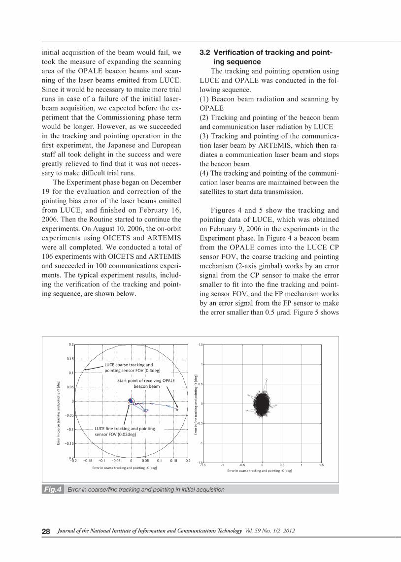
Figures 4 and 5 show the tracking and pointing data of LUCE, which was obtained on February 9, 2006 in the experiments in the Experiment phase. In Figure 4 a beacon beam from the OPALE comes into the LUCE CP sensor FOV, the coarse tracking and pointing mechanism (2-axis gimbal) works by an error signal from the CP sensor to make the error smaller to fit into the fine tracking and point-ing sensor FOV, and the FP mechanism works by an error signal from the FP sensor to make the error smaller than 0.5 μrad. Figure 5 shows
Error in coarse/fi ne tracking and pointing in initial acquisitionFig.4
28 Journal of the National Institute of Information and Communications Technology Vol. 59 Nos. 1/2 2012
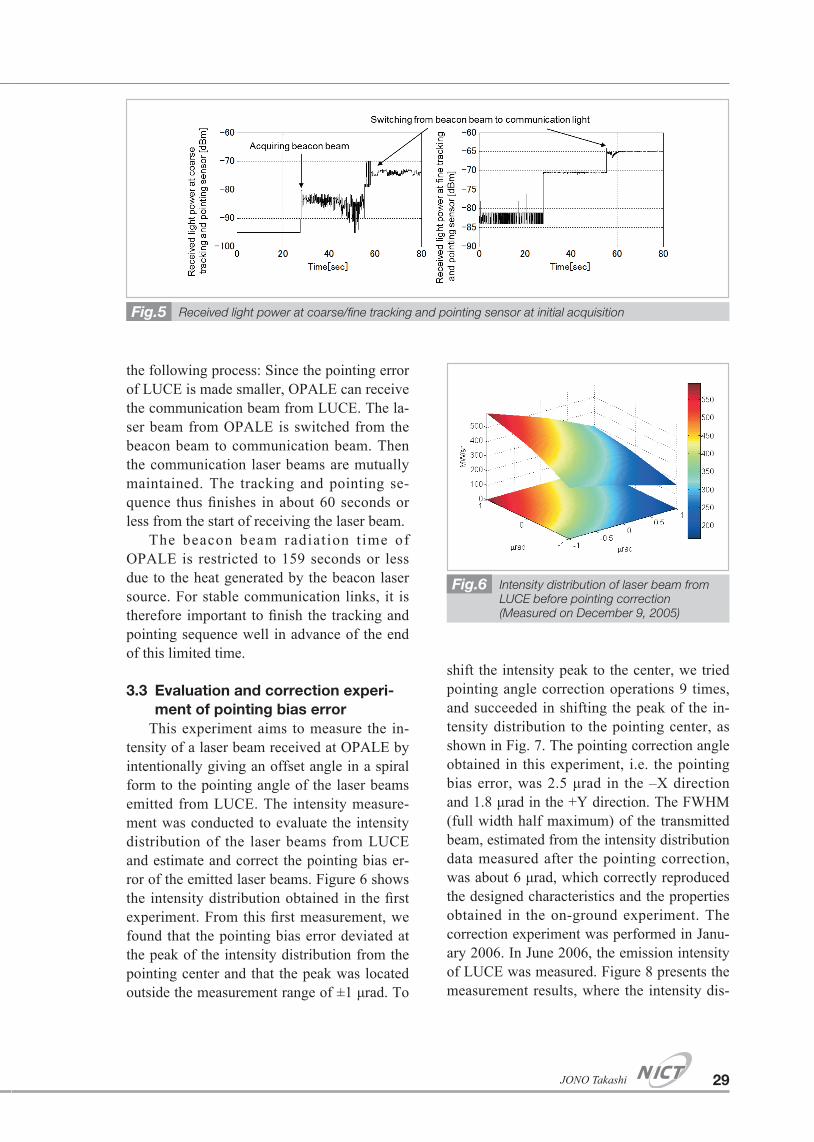
the following process: Since the pointing error of LUCE is made smaller, OPALE can receive the communication beam from LUCE. The la-ser beam from OPALE is switched from the beacon beam to communication beam. Then the communication laser beams are mutually maintained. The tracking and pointing se-quence thus finishes in about 60 seconds or less from the start of receiving the laser beam.
The beacon beam radiation t ime of OPALE is restricted to 159 seconds or less due to the heat generated by the beacon laser source. For stable communication links, it is therefore important to finish the tracking and pointing sequence well in advance of the end of this limited time.
3.3 Evaluation and correction experi-ment of pointing bias error
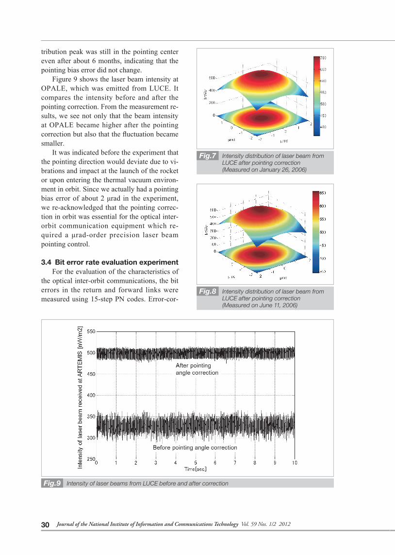
This experiment aims to measure the in-tensity of a laser beam received at OPALE by intentionally giving an offset angle in a spiral form to the pointing angle of the laser beams emitted from LUCE. The intensity measure-ment was conducted to evaluate the intensity distribution of the laser beams from LUCE and estimate and correct the pointing bias er-ror of the emitted laser beams. Figure 6 shows the intensity distribution obtained in the first experiment. From this first measurement, we found that the pointing bias error deviated at the peak of the intensity distribution from the pointing center and that the peak was located outside the measurement range of ±1 μrad. To
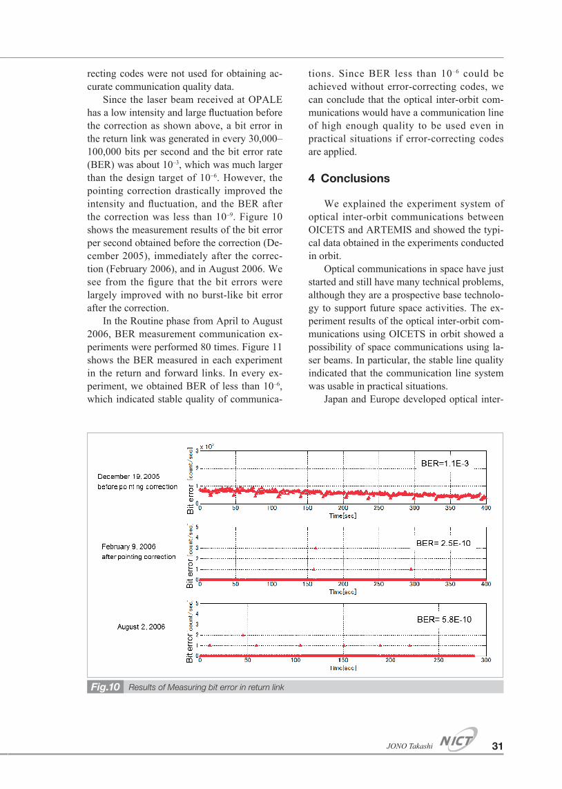
shift the intensity peak to the center, we tried pointing angle correction operations 9 times, and succeeded in shifting the peak of the in-tensity distribution to the pointing center, as shown in Fig. 7. The pointing correction angle obtained in this experiment, i.e. the pointing bias error, was 2.5 μrad in the –X direction and 1.8 μrad in the +Y direction. The FWHM (full width half maximum) of the transmitted beam, estimated from the intensity distribution data measured after the pointing correction, was about 6 μrad, which correctly reproduced the designed characteristics and the properties obtained in the on-ground experiment. The correction experiment was performed in Janu-ary 2006. In June 2006, the emission intensity of LUCE was measured. Figure 8 presents the measurement results, where the intensity dis-
Intensity distribution of laser beam from LUCE before pointing correction(Measured on December 9, 2005)
Fig.6
Received light power at coarse/fi ne tracking and pointing sensor at initial acquisitionFig.5
29JONO Takashi
tribution peak was still in the pointing center even after about 6 months, indicating that the pointing bias error did not change.
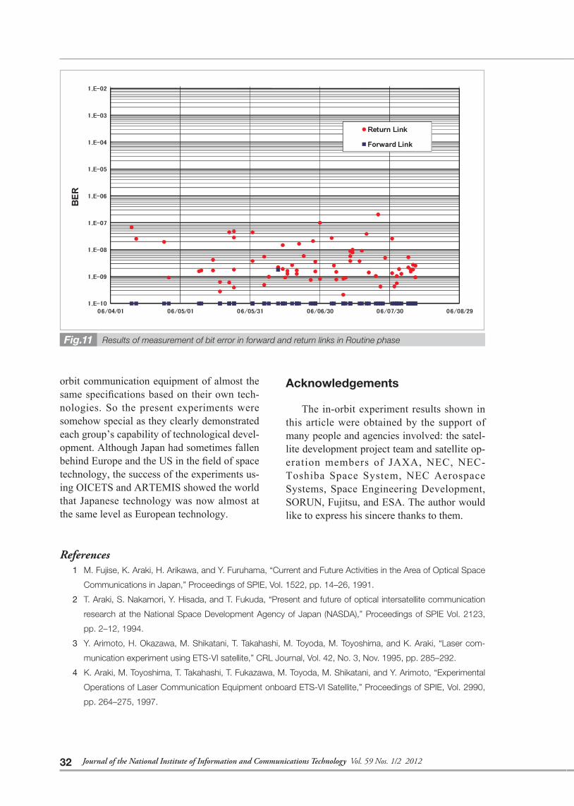
Figure 9 shows the laser beam intensity at OPALE, which was emitted from LUCE. It compares the intensity before and after the pointing correction. From the measurement re-sults, we see not only that the beam intensity at OPALE became higher after the pointing correction but also that the fluctuation became smaller.
It was indicated before the experiment that the pointing direction would deviate due to vi-brations and impact at the launch of the rocket or upon entering the thermal vacuum environ-ment in orbit. Since we actually had a pointing bias error of about 2 μrad in the experiment, we re-acknowledged that the pointing correc-tion in orbit was essential for the optical inter-orbit communication equipment which re-quired a μrad-order precision laser beam pointing control.
3.4 Bit error rate evaluation experimentFor the evaluation of the characteristics of
the optical inter-orbit communications, the bit errors in the return and forward links were measured using 15-step PN codes. Error-cor-
Intensity distribution of laser beam from LUCE after pointing correction(Measured on January 26, 2006)
Fig.7
Intensity distribution of laser beam from LUCE after pointing correction(Measured on June 11, 2006)
Fig.8
Intensity of laser beams from LUCE before and after correctionFig.9
30 Journal of the National Institute of Information and Communications Technology Vol. 59 Nos. 1/2 2012
recting codes were not used for obtaining ac-curate communication quality data.
Since the laser beam received at OPALE has a low intensity and large fluctuation before the correction as shown above, a bit error in the return link was generated in every 30,000–100,000 bits per second and the bit error rate (BER) was about 10–3, which was much larger than the design target of 10–6. However, the pointing correction drastically improved the intensity and fluctuation, and the BER after the correction was less than 10–9. Figure 10 shows the measurement results of the bit error per second obtained before the correction (De-cember 2005), immediately after the correc-tion (February 2006), and in August 2006. We see from the figure that the bit errors were largely improved with no burst-like bit error after the correction.
In the Routine phase from April to August 2006, BER measurement communication ex-periments were performed 80 times. Figure 11 shows the BER measured in each experiment in the return and forward links. In every ex-periment, we obtained BER of less than 10–6, which indicated stable quality of communica-
tions. Since BER less than 10–6 could be achieved without error-correcting codes, we can conclude that the optical inter-orbit com-munications would have a communication line of high enough quality to be used even in practical situations if error-correcting codes are applied.
4 Conclusions
We explained the experiment system of optical inter-orbit communications between OICETS and ARTEMIS and showed the typi-cal data obtained in the experiments conducted in orbit.
Optical communications in space have just started and still have many technical problems, although they are a prospective base technolo-gy to support future space activities. The ex-periment results of the optical inter-orbit com-munications using OICETS in orbit showed a possibility of space communications using la-ser beams. In particular, the stable line quality indicated that the communication line system was usable in practical situations.
Japan and Europe developed optical inter-
Results of Measuring bit error in return linkFig.10
31JONO Takashi
orbit communication equipment of almost the same specifications based on their own tech-nologies. So the present experiments were somehow special as they clearly demonstrated each group’s capability of technological devel-opment. Although Japan had sometimes fallen behind Europe and the US in the field of space technology, the success of the experiments us-ing OICETS and ARTEMIS showed the world that Japanese technology was now almost at the same level as European technology.
Acknowledgements
The in-orbit experiment results shown in this article were obtained by the support of many people and agencies involved: the satel-lite development project team and satellite op-eration members of JAXA, NEC, NEC-Toshiba Space System, NEC Aerospace Systems, Space Engineering Development, SORUN, Fujitsu, and ESA. The author would like to express his sincere thanks to them.
References1 M. Fujise, K. Araki, H. Arikawa, and Y. Furuhama, “Current and Future Activities in the Area of Optical Space
Communications in Japan,” Proceedings of SPIE, Vol. 1522, pp. 14–26, 1991.
2 T. Araki, S. Nakamori, Y. Hisada, and T. Fukuda, “Present and future of optical intersatellite communication
research at the National Space Development Agency of Japan (NASDA),” Proceedings of SPIE Vol. 2123,
pp. 2–12, 1994.
3 Y. Arimoto, H. Okazawa, M. Shikatani, T. Takahashi, M. Toyoda, M. Toyoshima, and K. Araki, “Laser com-
munication experiment using ETS-VI satellite,” CRL Journal, Vol. 42, No. 3, Nov. 1995, pp. 285–292.
4 K. Araki, M. Toyoshima, T. Takahashi, T. Fukazawa, M. Toyoda, M. Shikatani, and Y. Arimoto, “Experimental
Operations of Laser Communication Equipment onboard ETS-VI Satellite,” Proceedings of SPIE, Vol. 2990,
pp. 264–275, 1997.
Results of measurement of bit error in forward and return links in Routine phaseFig.11
32 Journal of the National Institute of Information and Communications Technology Vol. 59 Nos. 1/2 2012
JONO Takashi
Associate Senior Engineer, Tokyo Offi ce, Japan Aerospace Exploration Agency (JAXA)
Satellite System, Satellite Communica-tion
5 M. Faup, G. Planche, and T. Nielsen, “Experience Gained in the Frame of Silex Program Development and
Future Trends,” Proceedings of AIAA 16th International Communications Satellite Systems Conference 1996,
pp. 782–783.
6 T. Nielsen and G. Oppenhaeuser, “In Orbit Test Result of an Operational Intersatellite Link between ARTEMIS
and SPOT4,” Proceedings of SPIE Vol. 4635, pp. 1–15, 2002.
7 T. Jono, K. Nakagawa, and Y. Yamamoto, “Acquisition, tracking and pointing system of OICETS for free
space laser communications,” Proceedings of the SPIE 3692, pp. 41–50, 1999.
8 MOKUNO Masaaki, JONO Takashi, TAKAYAMA Yoshihisa, OHINATA Koichi, KURA Nobuhiro, FUJIWARA
Yuuichi, YAMAWAKI Toshihiko, USUKI Shigeru, ARAI Katsuyoshi, IKEBE Kenichi, SHIRATAMA Koichi,
OGURA Naoto, MASE Ichiro, FUJIWARA Koetsu, and TOYOTA Yasuhiro, “On-orbit Operation Results of Op-
tical Inter-orbit Communications Engineering Test Satellite (OICETS),” IEICE Technical Report, Vol. 106,
SANE2006–76, No. 107, June 2006. (in Japanese)
(Accepted March 14, 2012)
33JONO Takashi