Embed Size (px)
Citation preview

3 1176 00138 7720
NASA-TM-7286919790025328oNASA Teehnieal Memorandum 72869
,
CRITERIA FOR REPRESENTING CIRCULAR ARC ANDSINE WAVE SPAR WEBS BY NON-CURVED ELEMENTS
Jerald M. Jenkins
October 1979
: ill._ :",_-_I9
,,LANGLEY p,ESE.ARCH CENI EP,LIBI_,ARY,NASA
https://ntrs.nasa.gov/search.jsp?R=19790025328 2018-07-14T07:53:40+00:00Z

m

NASA Technical Memorandum 72869
CRITERIA FOR REPRESENTING CIRCULAR ARC ANDSINE WAVE SPAR WEBS BY NON-CURVED ELEMENTS
Jerald M. Jenkins
Dryden Flight Research CenterEdwards, California
w
NationalAeronauticsandSpaceAdministration1979


CRITERIA FOR REPRESENTING CIRCULAR ARC AND
SINE WAVE SPAR WEBS BY NON-CURVED ELEMENTS
Jerald M. Jenkins
Dryden Flight Research Center
INTRODUCTION
Thermal stresses are considered to be a major problem fordesigners and conceivers of airplanes to resolve. High speed air-craft that have been built (refs. 1 to 3) have incorporated thermalstress avoidance features in the structural component configurations.The conceivers of future aircraft also continue to try to avoidthe rigid characteristics that promote large thermal stresses (refs.4 and 5). One of the most popular thermal stress avoidanceapproaches is to use curved rather than flat webs for the spars.This effectively reduces the efficiency with which expansion inthe spar caps is transmitted through the spar web. The result isa significantly reduced level of thermal stress.
A significant design and analysis problem ensues when the prop-erties of these curved elements must be established for use with
• finite element structural models. Criteria is presented in thispaper which relates the extensional and rotational characteristicsof a specific dimensional circular arc and sine wave web to a flat
. web. This data is developed with respect to modeling details ofthe structure in reference 5.

SYMBOLS
A element area
E modulus of elasticity
F force
f mathematical function|
I moment of inertia
t thickness
x, y, z rectangular coordinates
displacement
8 rotation
Subscripts
C curved web
F flat web
i, j two discrete points
x, y, z designates the x, y, or z direction
refers to displacement
8 refers to rotation
DESCRIPTION OF STRUCTURAL REPRESENTATION
Contrasting sketches of a flat web and a curved web spar areshown in figure i. The spar web areas are normally at lower temp-eratures than the cap areas. This temperature differential betweenthe caps and the web results in differential longitudinal expansion,The longitudinal expansion of the caps is resisted by the shearcapability of the flat web which results in thermal stresses.
The level of thermal stress can be reduced by introducing acurved web. This reduction results because curved elements restrainthe longitudinal thermal growth less. A very significant problemarises when this diminished restraint must be defined in simpleterms for use in a finite element structural model. The primary
2

parameters that are changed by introducing a curved web are thelongitudinal (x-direction) stiffness and the resistance to rotationin the longitudinal direction (about the y-axis). The displacementin the x-directlon of a straight structural element whose ends areat x=i and x=j can be expressed as:
F (xi - x.)" X= ] (1)
A EX x
Likewise, the rotation of a similar straight structural elementwith ends at x=i and x=j can be represented by the integral of thebending moment..
i
0 = Y dx
Ex I (2)y3
Since the change to a curved web basically involves a reductionin axial (x-direction) displacement and in longitudinal (about they-axis) rotation, there should exist a set of flat web to curvedweb reduction factors that could be used in a finite element programsuch as NASTRAN (ref. 6). A calculation that results in a ratioof flat to curved web displacements and rotations for pertinentgeometric parameters (in this case the thickness of the web) pro-vides a criteria for inputting equivalent stiffness into a finiteelement. To be more specific, if the factors
_Ff6 = (3)
_C
and
eFf8 = -- (4)
8C
• can be calculated, then equations (I) and (2) could beequivalently expressed as follows for the curved web case:

Fx (xi - xj)= (5)
_x f_ Ax Ex
and
iM _
8y = Y dx (6)
E fo Iyj x
The simplest approach to use as input to the finite elementmodel would be to use the quantity (f_ _x ) for the area input and
the quantity (f8 Iy) for the moment of inertia so that the curvedelement properties could be used for a straight element assumption.
The factors of equations (3) and (4) can be determined asshown in figure 2 by applying unit forces and unit moments to bothflat and curved elements. Once the resulting displacements androtations are known then the flat to curved ratios can be calcu-lated.
It is important to not forget that to accomplish the simpli-fication outlined herein, the finite element computer program hasessentially been deceived. An important case in point is thatsince the area has been reduced to correct the axial stiffness,the computer program will consequently calculate axial stressesbased on that input area. All of the axial thermal stresses cal-culated for the elements with reduced areas must be corrected bymultiplying by the ratio of the input area to the real area. Al!of the axial thermal stresses in the unmodified elements (such asthe caps) will be correct as calculated. Although the bending ofthe element is of less than prime importance, a similar problemmust be considered when the moment of inertia is reduced.
DESCRIPTION OF NASTRAN MODELS
The flat web displacement and rotation due to a unit load canbe calculated directly from equations (i) and (2). However, cal-culations for the curved web case are more rigorous. A finiteelement model using NASTRAN was developed for both an element of asine wave web and a circular arc web. These models are depictedin figure 3. The models were derived for a single set of dimensions.
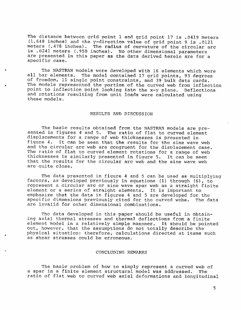
The distance between grid point 1 and grid point 17 is .0419 meters(1.648 inches) and the y_direction value of grid point 9 is .0121meters (.478 inches). The radius of curvature of the circular arcis .0241 meters (.950 inches). No other dimensional parametersare presented in this paper as the data derived herein are for aspecific case.
The NASTRAN models were developed with 16 elements which wereall bar elements. The model contained 17 grid points, 93 degreesof freedom, ii single point constraints, and 39 bulk data cards.
• The models represented the portion of the curved web from inflectionpoint to inflection point looking into the x_y plane. Deflectionsand rotations resulting from unit loads were calculated usingthese models.
RESULTS AND DISCUSSION
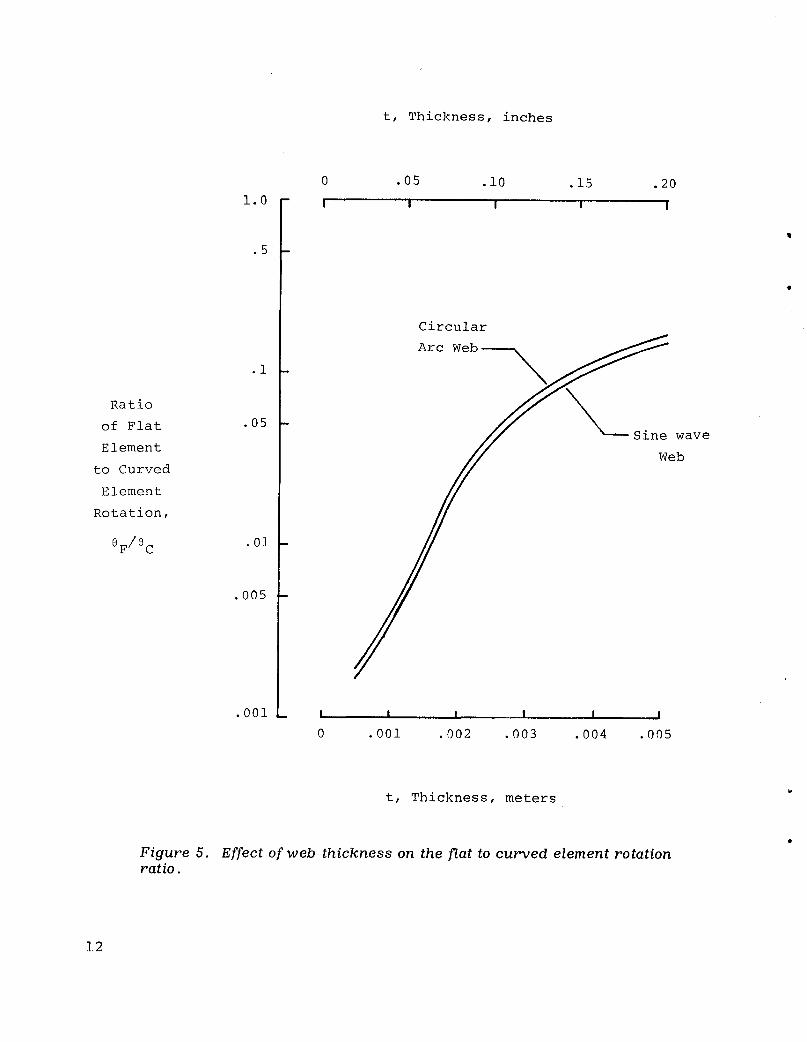
The basic results obtained from the NASTRAN models are pre-sented in figures 4 and 5. The ratio of flat to curved elementdisplacements for a ranqe of web thicknesses is presented infigure 4. It can be seen that the results for the sine wave weband the circular arc web are congruent for the displacement case.The ratio of flat to curved element rotations for a range of webthicknesses is similarly presented in figure 5. It can be seenthat the results for the circular arc web and the sine wave webare quite close.
The data presented in figure 4 and 5 can be used as multiplyingfactors, as developed previously in equations (i) through (6), torepresent a circular arc or sine wave spar web as a straight finiteelement or a series of straight elements. It is important toemphasize that the data in figures 4 and 5 are developed for thespecific dimensions previously cited for the curved webs. The dataare invalid for other dimensional combinations.
The data developed in this paper should be useful in obtain-ing axial thermal stresses and thermal deflections from a finiteelement model in a relatively simple mannner. It should be pointedout, however, that the assumptions do not totally describe thephysical situation; therefore, calculations directed at items suchas shear stresses could be erroneous.
CONCLUDING REMARKS
The basic problem of how to simply represent a curved web ofa spar in a finite element structural model was addressed. Theratio of flat web to curved web axial deformations and longitudinal

rotations were calculated using NASTRAN models. Multiplying factorswere developed from these calculations for various web thicknesses.These multiplying factors can be applied directly to the area andmoment of inertia inputs of the finite element model. This allowsthe thermal stress relieving configurations of sine wave and circ-ular arc webs to be simply accounted for in finite element struct-ural models.
o
Dryden Flight Research CenterNational Aeronautics and Space Administration
Edwards, Calif., October 20, 1979
REFERENCES
i. Jenkins, Jerald M.; and Kuhl, Albert E.: Recent Load CalibrationsExperience with the YF-12 Airplane. YF-12 Experiments Symposium,NASA CP-2054, Volume I, September 1978.
2. Stillwell, Wendell H.: X-15 Research Results. NASA SP-60, 1965.
3. Andrews, William H.: Summary of Preliminary Data Derived Fromthe XB-70 Airplanes. NASA TM-1240, 1966.
4. Plank, P. P.; Sakata, I. F.; Davis, G. W.; and Richie, C. C.:Hypersonic Cruise Vehicle Wing Structure Evaluation. NASA CR-1568, May, 1970.
5. Plank, P. P.; and Pennings, F. A.: Hypersonic Wing Test Struc-ture Design, Analysis, and Fabrication. NASA CR-127490, August,1973.
6. McCormick, Caleb W.,ed.: The NASTRAN User's Manual (Level 15).NASA SP-222(01), 1972.

z
(a) Flatweb spar. y _._ x
(b) Curved web spar.
Figure i. Sketch of flatweb in contrastto curved web spar.

Unit Force
U n i t Force
(a ) Axial displacement.
Figure 2 . Nomenclature of element loadings wi th resulting displacements and rotations.

Unit Moment
( b ) Longitudinal rotation.
Figure 2 . Concluded.

Y
7 8 9 I0 ii
6 _ 12
27 _',.__ •17
' X
(a) Sine-wave web.
Y
. 7 8 9 I0 Ii6 " 12
y
(b) Circular arc web.i
Figure 3. NASTRAN models representing sine-wave and circulararcconfigurations.
i0

t, Thickness, inches
0 .05 .10 .15 .20•i -- I I I I I
.05 -
Sine wave Web
.01 -
Ratio
of Flat .005
Element circular Arc Webto Curved
Element
Displacement,
4F/_C .001 -
.0005 -
.0001 - i I I I | !
0 .001 .002 .003 .004 .005
t, Thickness, meters
Figure 4. Effectofweb thickness on the J_atto curved element dispacementratio.
ii
t, Thickness, inches
0 .05 .i0 .15 .201.0- I I I I I
Circular
.i - Arc Web,S
//\Ratio
of Flat .05 -
aveElement
to Curved
Element
Rotation,
8F/8C .01 -
.005 -
.001 _ ! I I I I I
0 .001 .002 .003 .004 .005
w
t, Thickness, meters
Figure 5. Effectofweb thickness on the flattocurved element rotationratio.
12


1. Report No. 2. GovernmentAccessionNo. 3'. Recipient'sCatalogNo.NASA TM-72869
4. Title and Subtitle 5, Report Date
CRITERIAFOR REPRESENTING CIRCULAR ARC AND October1979SINEWAVE SPAR WEBS BY NON-CURVED ELEMENTS 6.PerformingOrganizationCode
7. Author(s) 8. Performing Organization Report No.
Jerald M. Jenkins H-1106 I
10. WorkUnitNo.9. PerformingOrganizationName and Address 505-02-54
NASA Dryden Flight Research Center 11. Contract or Grant No. QP.O. Box 273
Edwards, California93523i3. Type of Report and Period Covered
12. Sponsoring Agency Name and Address Technical Memorandum
NationalAeronauticsand SpaceAdministration 14.Sponsoring Agency CodeWashington, D .C. 20546
"i5. Supplementary Notes
16. Abstract
The basic problem of how to simply represent a curved web ofa spar in a finite element structural model was addressed. Theratio of flat web to curved web axial deformations and longitudinalrotations were calculated using NASTRAN models. Multiplying factorswere developed from these calculations for various web thicknesses.These multiplying factors can be applied directlv to the area andmoment of inertia inputs of the finite element model. This allowsthe thermal stress relieving configurations of sine wave and circ-ular arc webs to be simply accounted for in finite element struct-ural models.
V
17. Key Words(Suggestedby Author(s)) 18. Distribution Statement
Curved sparwebs Unclassified--UnlimitedFiniteelementmodelsStructural modeling 4
19. Security Classif.(of thisreport) 20. SecurityClassif.(of this page) 21. No. of Pages 22. Price*
Unclassified Unclassified 15 $3.25
*Forsaleby theNationalTechnicalInformationService,Springfield,Virginia22161


_JI
i!