Embed Size (px)
Citation preview

3/6/2006
‘Smart ways to save energy’
IntelliCon®
INSTALLATION MANUAL
Intellidyne, LLC 90 Pratt Oval
Glen Cove, NY 11542 516-676-0777
www.Intellidynellc.com

5/30/2006 3
Air Conditioning General Instructions:
General Wiring Instructions 2-1 2 Stage Air Cooled Air Conditioners 2-1
Heat Pump System 2-2 York Heat Pumps 2-2
Typical Packaged HVAC System 2-3 Typical 24vac Split A/C Air Handler 2-4 Typical 208/230vac Split A/C Air Handler 2-4 AC or CAC in Outdoor Condensing Section 2-5 Trane with Honeywell W973 Logic Panel 2-6, 7, 8 Trane “Voyager” with Interface Board 2-9 Trane “Voyager” without Interface Board 2-10, 11 Honeywell T775 Applications 2-12
HEATING Beckett HeatManager
Honeywell L7124A, C or L7148A 3-1 Honeywell L7124U 3-2 Honeywell L7148F 3-3 Honeywell L7224U Electronic Aquastat 3-4 Honeywell L8124A, C 3-5 Honeywell L8124E 3-6 Honeywell L8124G, L 3-7 Honeywell L8148A 3-8 Honeywell L8148E 3-9 Honeywell L8148J 3-10 Honeywell L8151A 3-11 Honeywell R7184A, B, P, U (Line Voltage Controller) 3-12 Honeywell R7184A, B, P, U (Low Voltage Controller) 3-13 Honeywell R7184A, B, P, U “REVISION 5” Model 3-14 Honeywell R8182D 3-15 Honeywell R8182E 3-16 Honeywell R8182F 3-17 Honeywell R8184G, K, L, N Cad Cell Relay 3-18 Honeywell R8184M, P 3-18
Honeywell R8285D 3-19 Riello Model 40F5 3-20 Cad Cell Relays General Instructions 3-21 Honeywell R8184G, K, L, N 3-22 Honeywell R8184M, P 3-22 Honeywell R7184A, B, P, U 3-23
3/6/2006
HEAT TIMER CHS/CHW with Mechanical Heat Timer 3-25 CHS/CHW with MPC Heat Timer 3-26 LCH with Mechanical Heat Timer 3-27 LCH with MPC Heat Timer 3-28 LCS with Mechanical Heat Timer 3-29 LCS with MPC Heat Timer 3-30
HW with Riello Model 40F5 3-31
Honeywell Aquastats (see Beckett HeatManager also)L7124A, C 3-32 L7124U 3-33 L7148F 3-34 L7224U Electronic Aquastat 3-35 L8124A, C 3-36 L8124E 3-37 L8124G, L 3-38 L8148A 3-39 L8148E 3-40 L8148J 3-41 L8151A 3-42 R7184A, B, P, U, (Line Voltage Controller) 3-43 R7184A, B, P, U, (Low Voltage Controller) 3-44R7184A, B, P, U, “REVISION 5” Model 3-45 R8182D 3-46R8182E 3-47 R8182F 3-48 Honeywell R8184G, K, L, N Cad Cell Relay 3-49 Honeywell R8184M, P 3-49 Honeywell R8285D 3-50 Riello Model 40F5 3-51
Fireye Flame Safeguard ControlsGeneral Instructions 3-52 CHS or CHW with: 24CJ5, Model 3010, 3011 3-53 24CU6, Model 1062, 1063 3-54 24CF6, Model 1010, 1011 3-55 25CU6, Model 5056 3-56 26CF6, Model 5023 3-57 24CJ5, Model 5015 3-58 25CU6 Model 3010, 3011 3-59 26CF6 Model 5022 3-60 EP (D)160, EP161, EP(D)170 3-61 Modular “M” Series 3-62
3/6/2006
UVM-1 3-63 UVM-1D, 1F, 2A, 3 or TFM -1D, 1F, 2A, 3 3-64 UVM-2A or TFM-2A 3-65 UVM-3 or TFM-3 3-66
LCH or LCS with: 24CJ5, Model 3010, 3011 3-67 24CU6, Model 1062, 1063 3-68 26CF6, Model 1010, 1011 3-69
25CU6, Model 5066 3-7025CF6, Model 5023 3-71 24CJ5 Model 5015 3-7225CU6 Model 5065 3-7326CF6, Model 5022 3-74EP (D)160, EP161, EP(D)170 3-75
Modular “M” Series 3-76 UVM-1 3-77 UVM-1D, 1F, 2A, 3 or TFM -1D, 1F, 2A, 3 3-78 UVM-2A or TFM-2A 3-79UVM-3 or TFM-3 3-80
Honeywell Flame Safeguard ControlsGeneral Instructions 3-81CHS or CHW with: R4140G, L, M or R4150A, C, X 3-82
R4795A, D 3-83 R7795A, B, C, D 3-84
RM7800 or RM7840E, G, L, M 3-85
LCH with: AO Smith DuraMax Models DB/DW 720-1810 3-86
LCH or LCS with: R890E, F, G 3-87 R4140G, L, M or R4150A, C, X 3-88 R4795A, D 3-89
R7795A, B, C, D 3-90 RM7800 or RM7840E, G, L, M 3-91
RM 7895 3-92
Refrigeration RU Wiring Precautions 4-1 RU Wiring Diagrams 4-2
3/21/2007 6
Pressure Control Operated, 115vac power/control 4-2 Pressure Control Operated, 220vac power/ control 4-3 Pump-down System, 220vac power/control 4-5 Pump-down System, 220vac power/24vac control 4-6 Pump-down System, 220vac power/115vac control 4-7
FA/CFA FA with Honeywell R8184G, K, L or N Cad Cell Relay 5-1 FA with Honeywell R8184 M or P Cad Cell Relay 5-1 FA with Honeywell R7184A, B, P, U Electronic Oil Primary 5-2 FA with Honeywell R7184A, B, P, U “Series 5 Relay 5-3 FA with Typical Residential Warm Air Furnace 5-4 FA with Riello Burner and Relay Module 5-5 CFA with Typical Packaged HVAC Unit 5-6
5/31/2006 1
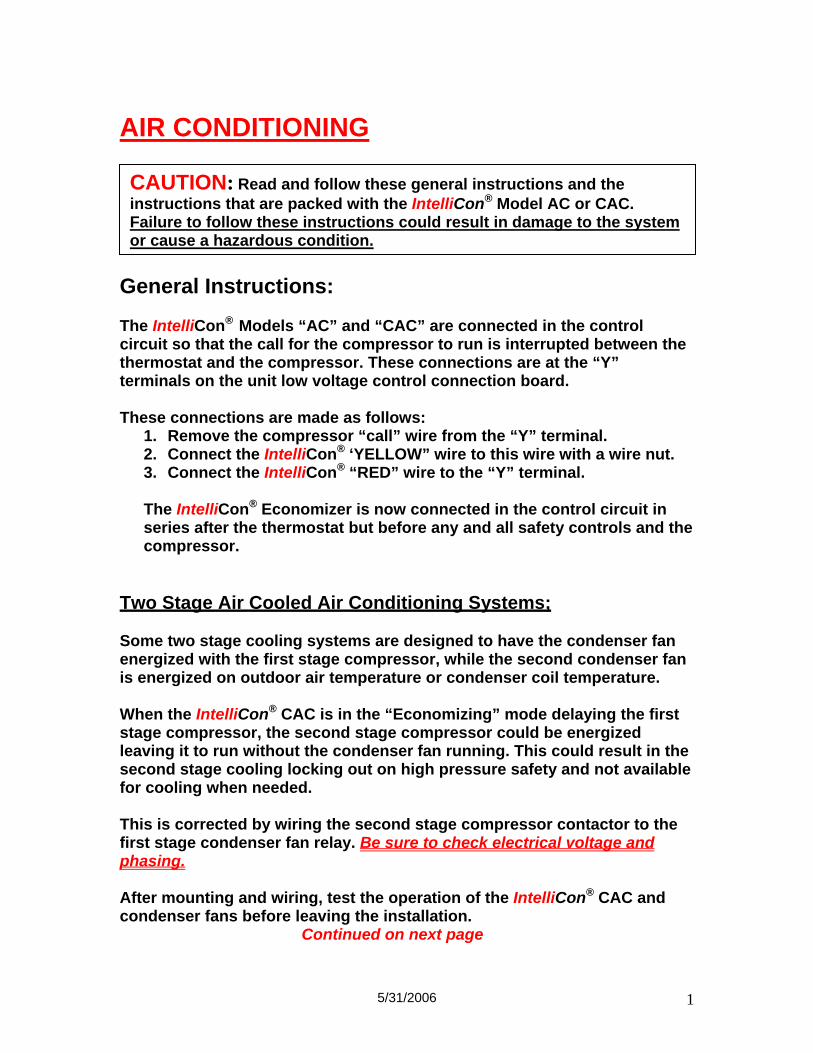
AIR CONDITIONING
General Instructions: The IntelliCon® Models “AC” and “CAC” are connected in the control circuit so that the call for the compressor to run is interrupted between the thermostat and the compressor. These connections are at the “Y” terminals on the unit low voltage control connection board. These connections are made as follows:
1. Remove the compressor “call” wire from the “Y” terminal. 2. Connect the IntelliCon® ‘YELLOW” wire to this wire with a wire nut. 3. Connect the IntelliCon® “RED” wire to the “Y” terminal. The IntelliCon® Economizer is now connected in the control circuit in series after the thermostat but before any and all safety controls and the compressor.
Two Stage Air Cooled Air Conditioning Systems; Some two stage cooling systems are designed to have the condenser fan energized with the first stage compressor, while the second condenser fan is energized on outdoor air temperature or condenser coil temperature. When the IntelliCon® CAC is in the “Economizing” mode delaying the first stage compressor, the second stage compressor could be energized leaving it to run without the condenser fan running. This could result in the second stage cooling locking out on high pressure safety and not available for cooling when needed. This is corrected by wiring the second stage compressor contactor to the first stage condenser fan relay. Be sure to check electrical voltage and phasing. After mounting and wiring, test the operation of the IntelliCon® CAC and condenser fans before leaving the installation. Continued on next page
CAUTION: Read and follow these general instructions and the instructions that are packed with the IntelliCon® Model AC or CAC. Failure to follow these instructions could result in damage to the system or cause a hazardous condition.
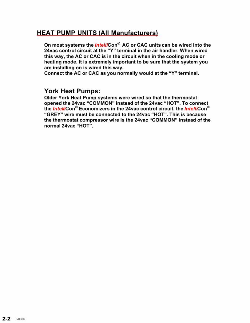
HEAT PUMP UNITS (All Manufacturers)
On most systems the IntelliCon® AC or CAC units can be wired into the 24vac control circuit at the “Y” terminal in the air handler. When wired this way, the AC or CAC is in the circuit when in the cooling mode or heating mode. It is extremely important to be sure that the system you are installing on is wired this way.Connect the AC or CAC as you normally would at the “Y” terminal.
York Heat Pumps:Older York Heat Pump systems were wired so that the thermostat opened the 24vac “COMMON” instead of the 24vac “HOT”. To connect the IntelliCon® Economizers in the 24vac control circuit, the IntelliCon®
“GREY” wire must be connected to the 24vac “HOT”. This is because the thermostat compressor wire is the 24vac “COMMON” instead of the normal 24vac “HOT”.
2-2 3/06/06
Inte
llid
yne
DW
G. #
DW
GD
ES
C
DW
G#
DA
TE
:D
AT
E
90 P
ratt
Ova
lG
len
Co
ve, N
Y
1154
2(5
16)
676-
0777
CU
STN
AM
E
Inte
lliC
on
CA
C
BR
OW
N
TA
PE
OF
FIN
DIV
IDU
AL
LY
BL
UE
VIO
LE
T
L1
L2
WH
ITE
BL
AC
K
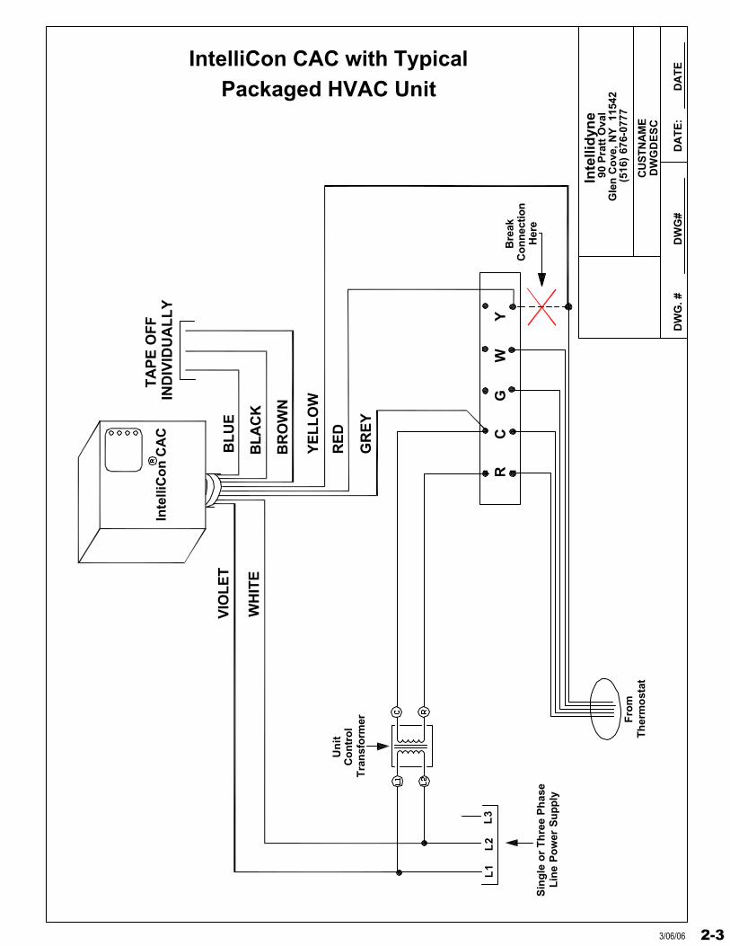
IntelliCon CAC with Typical Packaged HVAC Unit
RE
D
YE
LL
OW
GR
EY
L3
R
C
G
W
Y
Fro
mT
her
mo
stat
Bre
akC
on
nec
tion
Her
e
Un
itC
on
tro
lT
ran
sfo
rmer
Lin
e P
ow
er S
up
ply
Sin
gle
or
Th
ree
Ph
ase
2-33/06/06
Inte
llid
yne
DW
G. #
DW
GD
ES
C
DW
G#
DA
TE
:D
AT
E
90 P
ratt
Ova
lG
len
Co
ve, N
Y
1154
2(5
16)
676-
0777
CU
STN
AM
E
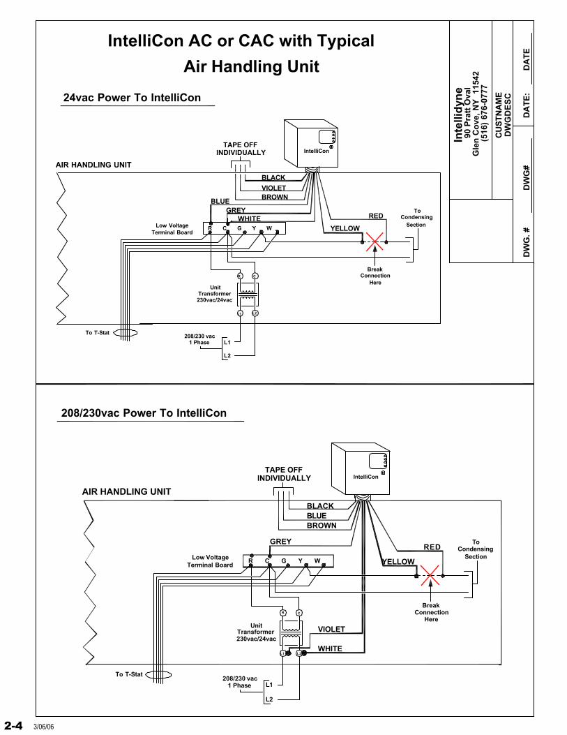
Air Handling Unit
IntelliCon AC or CAC with Typical
IntelliCon
BROWNVIOLET
BLACK
WHITEYELLOW
GREYRED
BLUE
L1
L2
1 Phase208/230 vac
UnitTransformer230vac/24vac
AIR HANDLING UNIT
Low VoltageTerminal Board
R C G Y W
To T-Stat
INDIVIDUALLYTAPE OFF
ToCondensing
Section
ConnectionHere
Break
VIOLET
BROWN
R C G Y W
BLACK
Condensing
ConnectionBreak
Here
To
SectionRED
YELLOW
IntelliCon
AIR HANDLING UNIT
To T-Stat
230vac/24vac
L2
L1208/230 vac 1 Phase
TransformerUnit
Low VoltageTerminal Board
BLUE
GREY
WHITE
INDIVIDUALLYTAPE OFF
208/230vac Power To IntelliCon
24vac Power To IntelliCon
L1 L2
R C
R C
L2L1
2-4 3/06/06
Inte
llid
yne
DW
G. #
DW
GD
ES
C
DW
G#
DA
TE
:D
AT
E
90 P
ratt
Ova
lG
len
Co
ve, N
Y
1154
2(5
16)
676-
0777
CU
STN
AM
E
IntelliCon
BROWN
TAPE OFFINDIVIDUALLY
BLUE
VIOLET
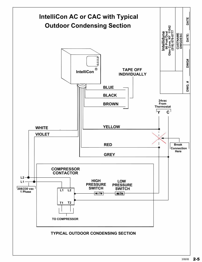
TYPICAL OUTDOOR CONDENSING SECTION
COMPRESSORCONTACTOR
L1 L2
T1 T2
208/230 vac 1 Phase
L1L2
WHITE
BLACK
HIGHPRESSURE
SWITCH
LOWPRESSURE
SWITCH
TO COMPRESSOR
IntelliCon AC or CAC with Typical Outdoor Condensing Section
RED
YELLOW
GREY
Y C
BreakConnection
Here
FromThermostat
24vac
2-53/06/06
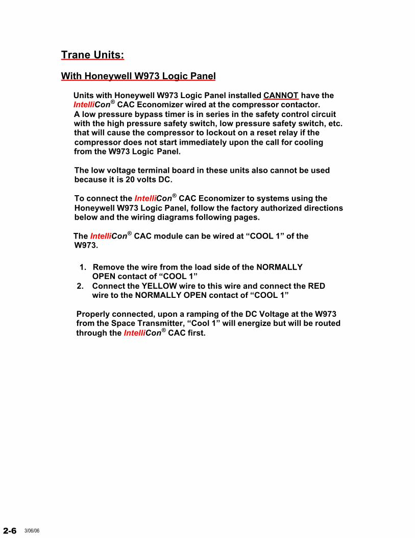
Trane Units:
With Honeywell W973 Logic Panel
Units with Honeywell W973 Logic Panel installed CANNOT have theIntelliCon® CAC Economizer wired at the compressor contactor.
A low pressure bypass timer is in series in the safety control circuit with the high pressure safety switch, low pressure safety switch, etc. that will cause the compressor to lockout on a reset relay if the
compressor does not start immediately upon the call for cooling from the W973 Logic Panel.
The low voltage terminal board in these units also cannot be usedbecause it is 20 volts DC.
To connect the IntelliCon® CAC Economizer to systems using theHoneywell W973 Logic Panel, follow the factory authorized directionsbelow and the wiring diagrams following pages.
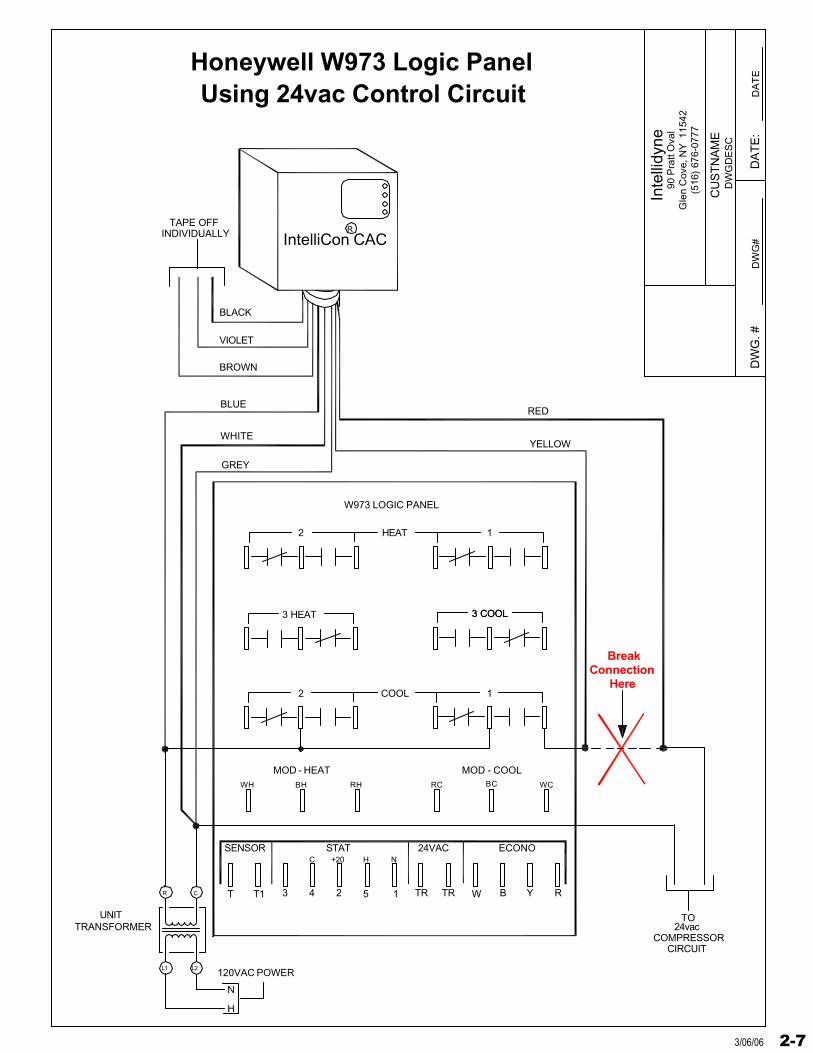
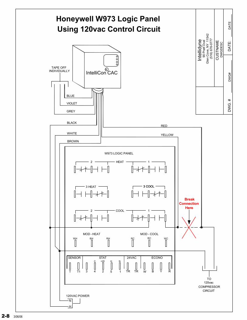
The IntelliCon® CAC module can be wired at “COOL 1” of theW973.
1. Remove the wire from the load side of the NORMALLY OPEN contact of “COOL 1”
2. Connect the YELLOW wire to this wire and connect the REDwire to the NORMALLY OPEN contact of “COOL 1”
Properly connected, upon a ramping of the DC Voltage at the W973 from the Space Transmitter, “Cool 1” will energize but will be routed
through the IntelliCon® CAC first.
2-6 3/06/06
Inte
llidy
ne
DW
G. #
DW
GD
ES
C
DW
G#
DA
TE
:D
AT
E
90 P
ratt
Ova
lG
len
Cov
e, N
Y 1
1542
(516
) 67
6-07
77
CU
ST
NA
ME
W973 LOGIC PANEL
3 HEAT
MOD - HEAT
4
WH
SENSOR
T T1 3
C
BH
2
2
TR
STAT
2
+20
5
H
RH
24VAC
TR1
N
RC
COOL
MOD - COOL
ECONO
W
BC WC
1
3 COOL3 COOL
HEAT 1
B RY
IntelliCon CACR
Honeywell W973 Logic Panel
120VAC POWER
N
H
L2L1
CR
UNITTRANSFORMER
YELLOW
BLUE
WHITE
GREY
BLACK
RED
BROWN
VIOLET
TAPE OFF INDIVIDUALLY
BreakConnection
Here
TO
COMPRESSORCIRCUIT
24vac
Using 24vac Control Circuit
2-73/06/06
Inte
llidy
ne
DW
G. #
DW
GD
ES
C
DW
G#
DA
TE
:D
AT
E
90 P
ratt
Ova
lG
len
Cov
e, N
Y 1
1542
(516
) 67
6-07
77
CU
ST
NA
ME
W973 LOGIC PANEL
3 HEAT
MOD - HEAT
4
WH
SENSOR
T T1 3
C
BH
2
2
TR
STAT
2
+20
5
H
RH
24VAC
TR1
N
RC
COOL
MOD - COOL
ECONO
W
BC WC
1
3 COOL3 COOL
HEAT 1
B RY
IntelliCon CACR
Honeywell W973 Logic Panel
120VAC POWER
N
H
YELLOW
BLACK
WHITE
BROWN
BLUE
RED
GREY
VIOLET
TAPE OFF INDIVIDUALLY
BreakConnection
Here
TO
COMPRESSORCIRCUIT
120vac
Using 120vac Control Circuit
2-8 3/06/06
TRANE “VOYAGER”
WITH THERMOSTAT INTERFACE BOARD
These units utilize a “normal” electronic or electro-mechanicalthermostat. Connect the IntelliCon® CAC to the Low Voltage Terminal Board in the Trane unit as follows:
IMPORTANT; The following directions represent only one of the many variations of the Low Voltage Wiring Schematic supplied with the Trane Thermostat Interface Board due to changes in the Trane Voyager unit.CONSULT THE UNITS THERMOSTAT INTERFACE BOARD WIRING DIAGRAM FOR THE PROPER TERMINALS.
1. Remove the thermostat “Y1” wire from terminal on the low voltage terminal board (LTB).
2. Connect the YELLOW wire from the IntelliCon® CAC to the wireyou just removed.
3. Connect the RED wire from the IntelliCon® to the terminal where you removed the “Y1” wire from the thermostat on the low voltage
terminal board (LTB).
2-93/06/06
Trane “VOYAGER”
WITHOUT THERMOSTAT INTERFACE BOARD
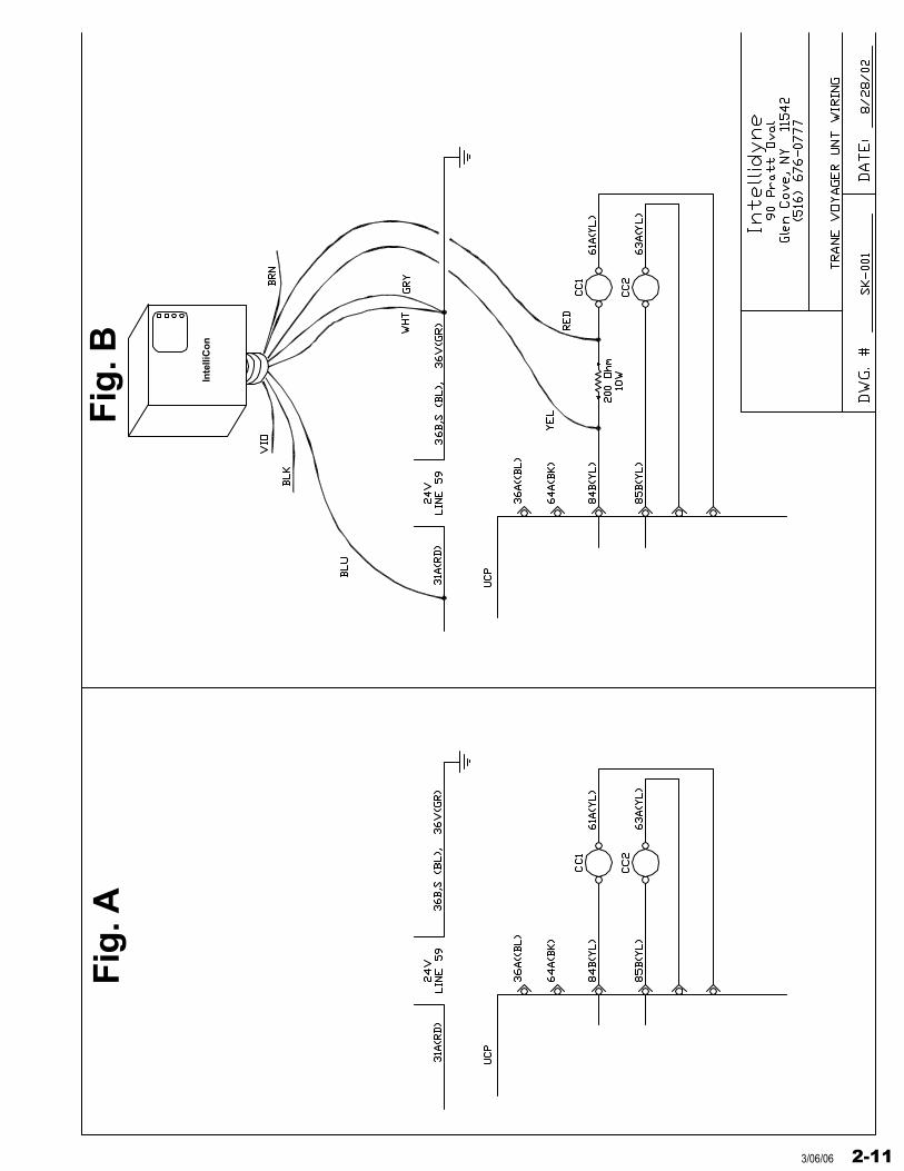
These units CANNOT have the IntelliCon® CAC wired at the low voltageterminal board. Without the Thermostat Interface Board, a Trane “ZONE SENSOR” is used instead of a conventional thermostat and utilizes aDC voltage ramp. The IntelliCon® CAC MUST be wired at compressor #1 contactor as shown in the diagram. Follow the same directions if the unit has 2 compressors.
Figure “A” shows the factory wiring of compressor #1 contactor.
Figure “B” shows how to wire in the IntelliCon® CAC using a200 ohm, 10 watt resistor. This resistor must be used to complete a voltage circuit backto the UPC board or the UPC board will lock the compressorout, requiring a manual reset of the unit.
To connect the IntelliCon® CAC to this configuration use thewiring diagrams on the following page.
2-10 3/06/06
Inte
lliC
on
Fig
. AF
ig. B
2-113/06/06
Inte
llid
yne
DW
G. #
DW
GD
ES
C
DW
G#
DA
TE
:D
AT
E
90 P
ratt
Ova
lG
len
Co
ve, N
Y 1
1542
(516
) 67
6-07
77
CU
STN
AM
E
BLUE
GREY
VIOLET
INDIVIDUALLYTAPE OFF
B2 B1
HONEYWELL
TYPICAL
BLACK
BROWN
YELLOW
RED
TTL1 L2
C1
C2
WHITE
H
N
120
VAC
ZC
ZR
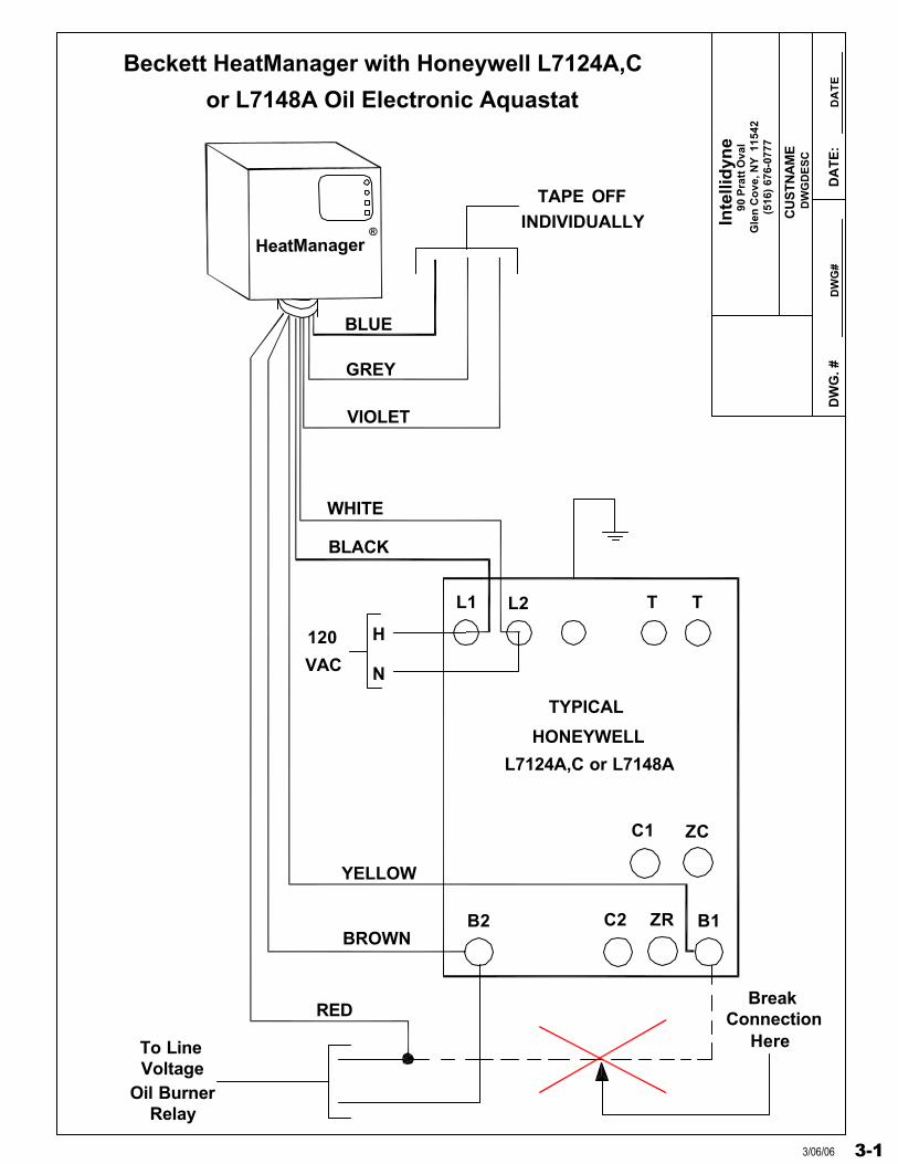
Beckett HeatManager with Honeywell L7124A,C
HeatManager®
L7124A,C or L7148A
or L7148A Oil Electronic Aquastat
ConnectionBreak
HereTo LineVoltage
Oil BurnerRelay
3-13/06/06
Inte
llid
yne
DW
G. #
DW
GD
ES
C
DW
G#
DA
TE
:D
AT
E
90 P
ratt
Ova
lG
len
Co
ve, N
Y 1
1542
(516
) 67
6-07
77
CU
STN
AM
E
BLUE
GREY
VIOLET
INDIVIDUALLYTAPE OFF
B2 B1
HONEYWELL
TYPICAL
BLACK
BROWN
YELLOW
RED
TTL1 L2
C1
C2
WHITE
H
N
120
VAC
ZC
ZR
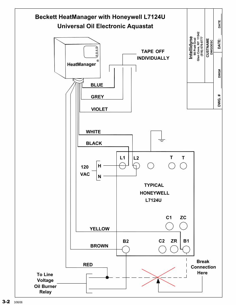
Beckett HeatManager with Honeywell L7124U
HeatManager®
L7124U
Universal Oil Electronic Aquastat
ConnectionBreak
HereTo LineVoltage
Oil BurnerRelay
3-2 3/06/06
Inte
llid
yne
DW
G. #
DW
GD
ES
C
DW
G#
DA
TE
:D
AT
E
90 P
ratt
Ova
lG
len
Co
ve, N
Y 1
1542
(516
) 67
6-07
77
CU
STN
AM
E
HO
NE
YW
EL
L
TY
PIC
AL
120
VA
C
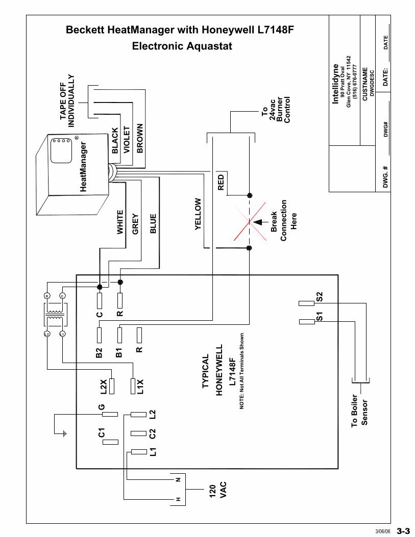
Beckett HeatManager with Honeywell L7148F
Hea
tMan
ager
®
L71
48F
Electronic Aquastat
Co
nn
ecti
on
Bre
ak
Her
e
To
Bu
rner
24va
c
Co
ntr
ol
GC
1L
2X
L1X
B2
B1 R
C R
L1
C2
L2
S1
S2
NH
L1L2
CR
TA
PE
OF
FIN
DIV
IDU
AL
LY
WH
ITE
BLU
E
GR
EY
VIO
LE
T
BL
AC
K
BR
OW
N
RE
D
YE
LL
OW
NO
TE
: No
t All
Ter
min
als
Sh
ow
n
To
Bo
iler
Sen
sor
3-33/06/06
Inte
llid
yne
DW
G. #
D
AT
E:
90 P
ratt
Ova
lG
len
Co
ve, N
Y
1154
2(5
16)
676-
0777
CU
STN
AM
E
IND
IVID
UA
LL
YT
AP
E O
FF
GR
EY
BLU
E
BR
OW
N
Hea
tMan
ager
WH
ITE
BL
AC
KV
IOL
ET
ZR
L1
L2
C2
B2
C1
B1
ZC
TY
PIC
AL
L72
24U
1
2
T 3
T
(No
t A
llT
erm
inal
sA
nd
Wir
ing
YE
LL
OW
RE
DS
ho
wn
)
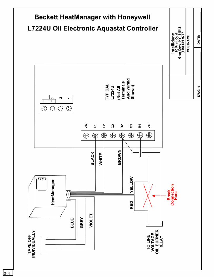
L7224U Oil Electronic Aquastat Controller
Beckett HeatManager with Honeywell
Her
eC
on
nec
tio
nB
reak
TO
LIN
E
RE
LAY
OIL
BU
RN
ER
VO
LT
AG
E
3-4
Inte
llid
yne
DW
G. #
DW
GD
ES
C
DW
G#
DA
TE
:
90 P
ratt
Ova
lG
len
Co
ve, N
Y 1
1542
(516
) 67
6-07
77
CU
STN
AM
E
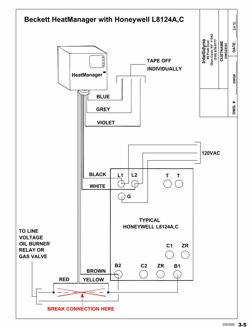
HeatManager
L1 L2
G
VIOLET
GREY
BLUE
TAPE OFF
BREAK CONNECTION HERE
INDIVIDUALLY
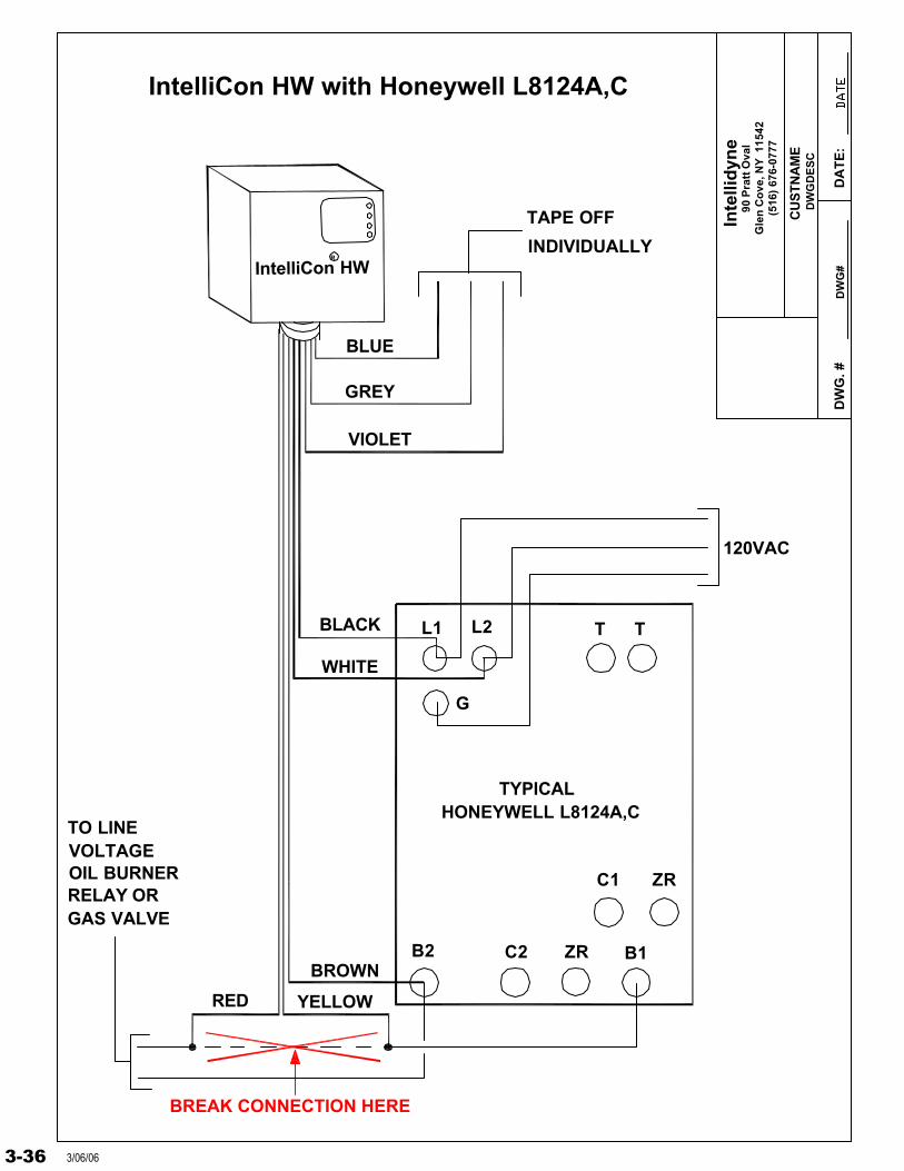
TYPICALHONEYWELL L8124A,C
T T
B2
C1 ZR
C2 ZR B1
BLACK
WHITE
BROWN
TO LINEVOLTAGEOIL BURNERRELAY ORGAS VALVE
YELLOWRED
120VAC
Beckett HeatManager with Honeywell L8124A,C
3-53/06/2006
Inte
llid
yne
DW
G. #
DW
GD
ES
C
DW
G#
DA
TE
:D
AT
E
90 P
ratt
Ova
lG
len
Co
ve, N
Y 1
1542
(516
) 67
6-07
77
CU
STN
AM
E
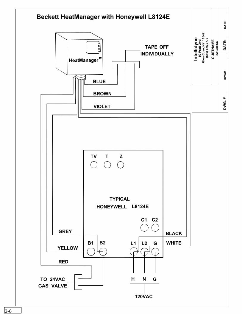
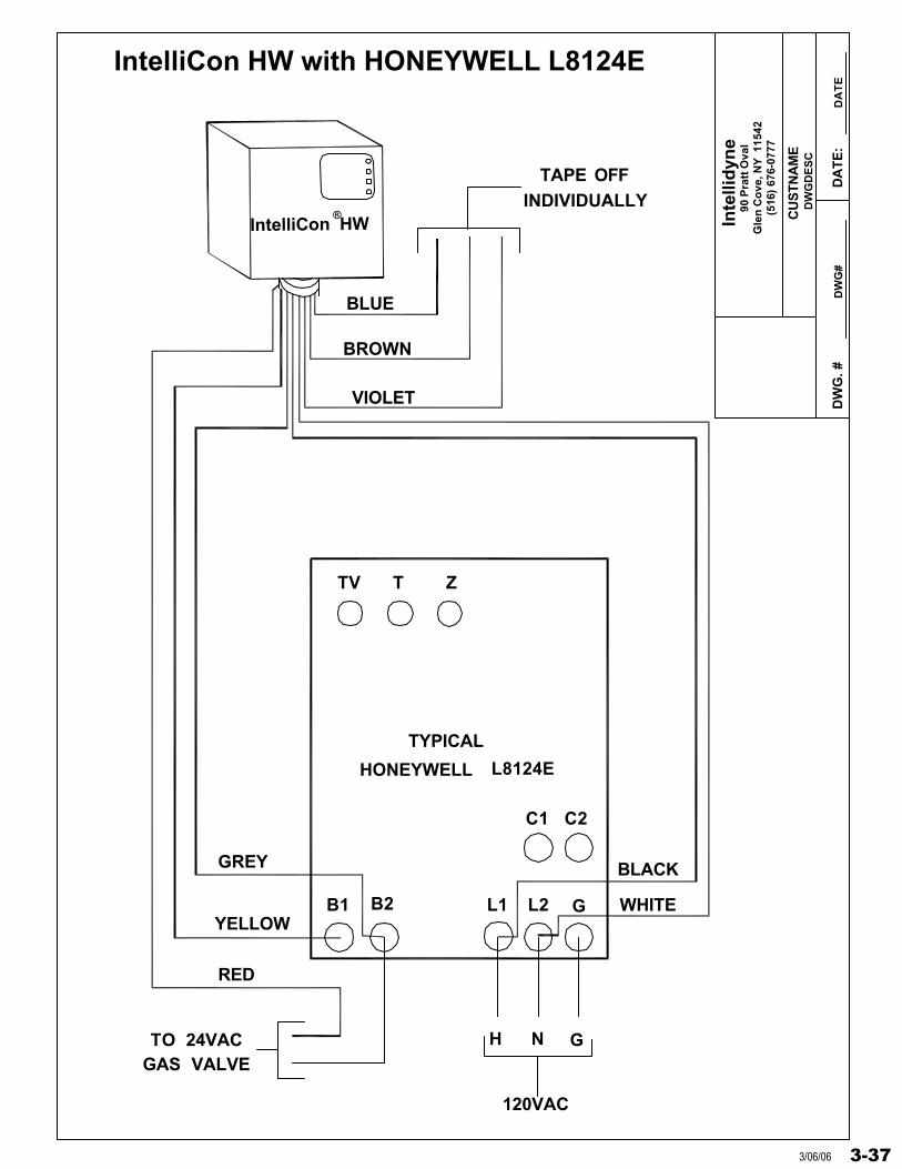
HeatManager
TV T Z
BLUE
BROWN
VIOLET
INDIVIDUALLYTAPE OFF
L2L1
C2C1
B1 B2
L8124EHONEYWELL
TYPICAL
H N
120VAC
WHITE
BLACKGREY
YELLOW
RED
TO 24VACGAS VALVE
G
G
Beckett HeatManager with Honeywell L8124E
3-6
Inte
llid
yne
DW
G. #
DW
GD
ES
C
DW
G#
DA
TE
:D
AT
E
90 P
ratt
Ova
lG
len
Co
ve, N
Y 1
1542
(516
) 67
6-07
77
CU
STN
AM
E
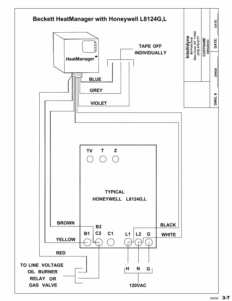
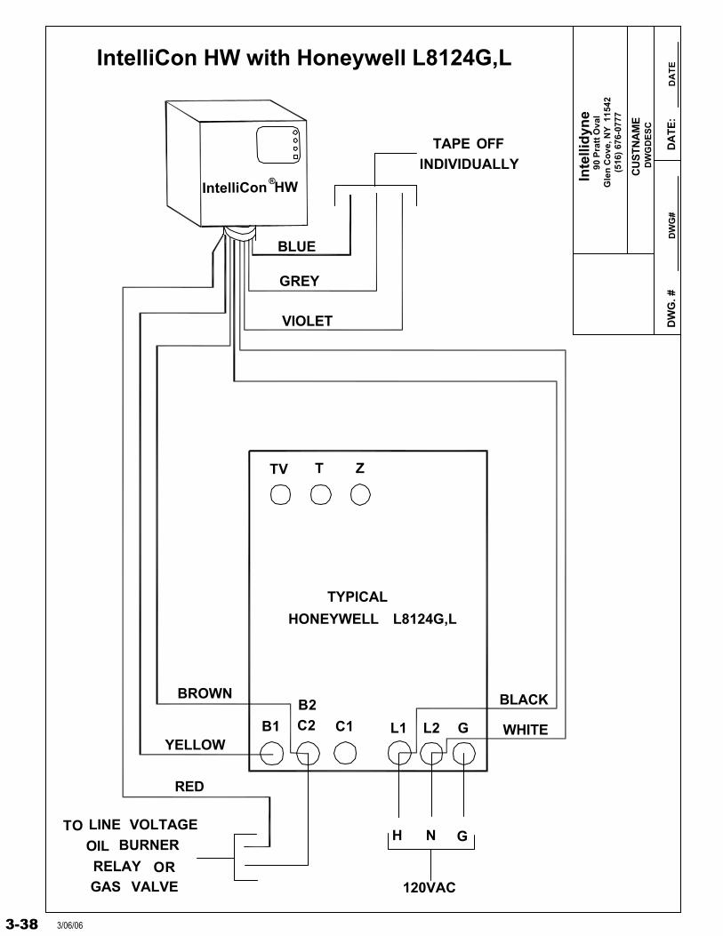
HeatManager
TV T Z
BLUE
BROWN
VIOLET
INDIVIDUALLYTAPE OFF
L2L1
B2
C1B1 C2
L8124G,LHONEYWELL
TYPICAL
H N
120VAC
WHITE
BLACK
GREY
YELLOW
RED
G
GTO LINE VOLTAGE
OIL BURNER
RELAY ORGAS VALVE
Beckett HeatManager with Honeywell L8124G,L
3-73/06/06
Inte
llid
yne
DW
G. #
DW
GD
ES
C
DW
G#
DA
TE
:D
AT
E
90 P
ratt
Ova
lG
len
Co
ve, N
Y 1
1542
(516
) 67
6-07
77
CU
STN
AM
E
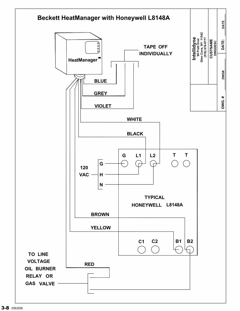
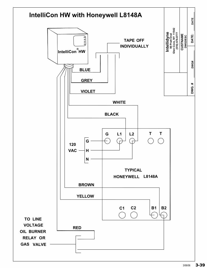
HeatManager
BLUE
GREY
VIOLET
INDIVIDUALLYTAPE OFF
B2B1
L8148AHONEYWELL
TYPICAL
BLACK
BROWN
YELLOW
RED
TTG L1 L2
C1 C2
WHITE
G
H
N
120
VAC
TO LINE
VOLTAGE
OIL BURNER
RELAY OR
GAS VALVE
Beckett HeatManager with Honeywell L8148A
3-8 3/06/2006

Inte
llid
yne
DW
G. #
DW
GD
ES
C
DW
G#
DA
TE
:D
AT
E
90 P
ratt
Ova
lG
len
Co
ve, N
Y 1
1542
(516
) 67
6-07
77
CU
STN
AM
E
HeatManager
TV W T
Z
BLUE
BROWN
VIOLET
INDIVIDUALLYTAPE OFF
L2L1
C2C1
B1 B2
L8148EHONEYWELL
TYPICAL
H N
120VAC
WHITE
BLACK
GREY
YELLOW
RED
TO 24VACGAS VALVE
Beckett HeatManager with Honeywell L8148E
3-93/06/06
Inte
llid
yne
DW
G. #
DW
GD
ES
C
DW
G#
DA
TE
:D
AT
E
90 P
ratt
Ova
lG
len
Co
ve, N
Y 1
1542
(516
) 67
6-07
77
CU
STN
AM
E
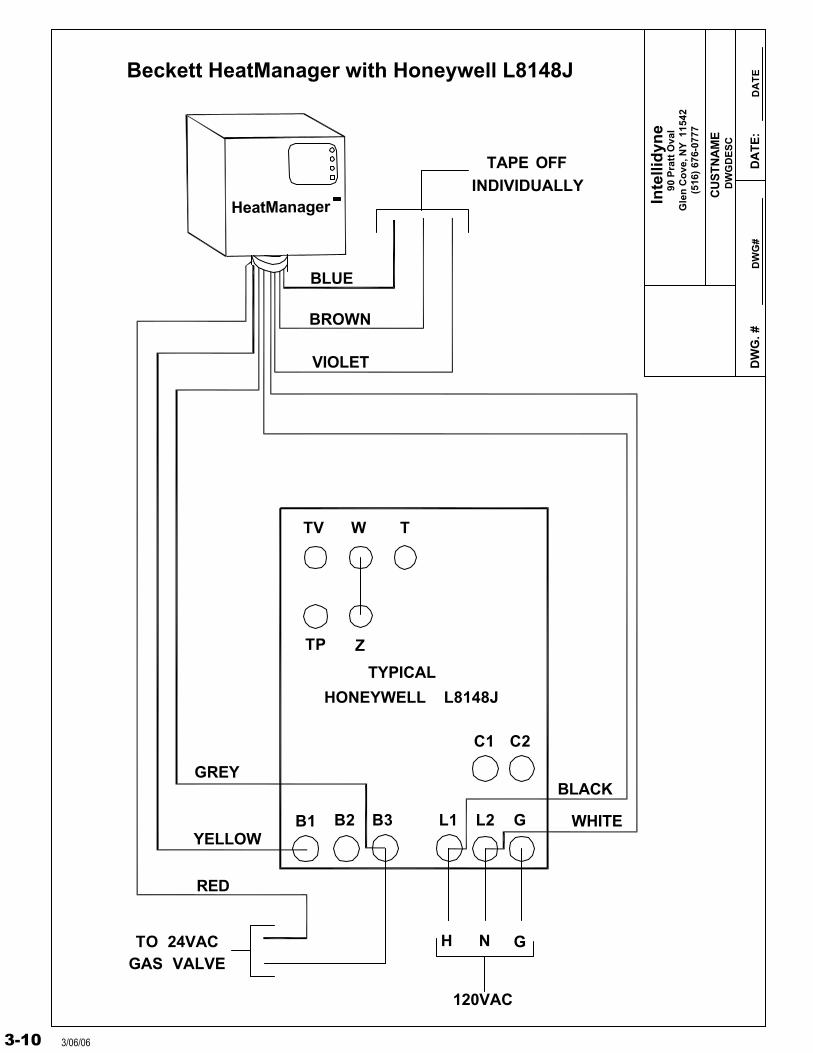
TV W T
Z
BLUE
BROWN
VIOLET
INDIVIDUALLYTAPE OFF
L2L1
C2C1
B1 B2
L8148JHONEYWELL
TYPICAL
H N
120VAC
WHITE
BLACKGREY
YELLOW
RED
TO 24VACGAS VALVE
GB3
G
TP
HeatManager
Beckett HeatManager with Honeywell L8148J
3-10 3/06/06
Inte
llid
yne
DW
G. #
DW
GD
ES
C
DW
G#
DA
TE
:D
AT
E
90 P
ratt
Ova
lG
len
Co
ve, N
Y 1
1542
(516
) 67
6-07
77
CU
STN
AM
E
HeatManager
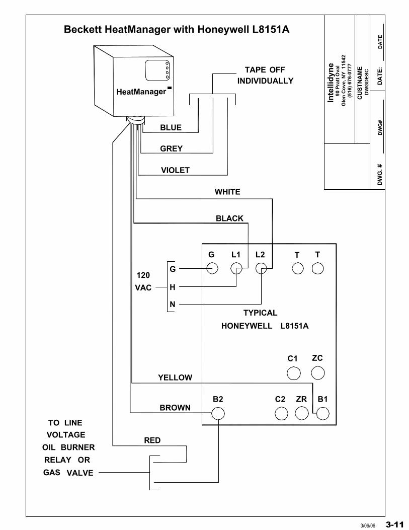
BLUE
GREY
VIOLET
INDIVIDUALLYTAPE OFF
B2 B1
L8151AHONEYWELL
TYPICAL
BLACK
BROWN
YELLOW
RED
TTG L1 L2
C1
C2
WHITE
G
H
N
120
VAC
TO LINE
VOLTAGE
OIL BURNER
RELAY OR
GAS VALVE
ZC
ZR
Beckett HeatManager with Honeywell L8151A
3-113/06/06
Inte
llid
yne
DW
G. #
DW
GD
ES
C
DW
G#
DA
TE
:D
AT
E
90 P
ratt
Ova
lG
len
Co
ve, N
Y 1
1542
(516
) 67
6-07
77
CU
STN
AM
E
HO
NE
YW
EL
LT
YP
ICA
L
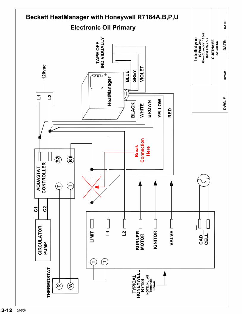
Beckett HeatManager with Honeywell R7184A,B,P,U
Hea
tMan
ager
®
R71
84
Electronic Oil Primary
Co
nn
ecti
on
Bre
ak
Her
e
C1
B2
B1
L1C
2L2
TA
PE
OF
FIN
DIV
IDU
AL
LY
WH
ITE
BLU
E
GR
EY
VIO
LE
T
BL
AC
K
BR
OW
N
RE
D
YE
LL
OW
NO
TE
: No
t All
CA
DC
EL
L
TH
ER
MO
ST
AT
CIR
CU
LA
TO
RP
UM
P
R WTT
Ter
min
als
Sho
wn
AQ
UA
ST
AT
CO
NT
RO
LL
ER
T T
120v
ac
BU
RN
ERL2L1
MO
TO
R
LIM
IT
VA
LV
E
IGN
ITO
R
3-12 3/06/06
Inte
llidy
ne
DW
G. #
DW
GD
ES
C
DW
G#
DA
TE
:D
AT
E
90 P
ratt
Ova
lG
len
Cov
e, N
Y 1
1542
(516
) 67
6-07
77
CU
ST
NA
ME
IND
IVID
UA
LLY
TA
PE
OF
F
BLU
E
VIO
LET
GR
EY
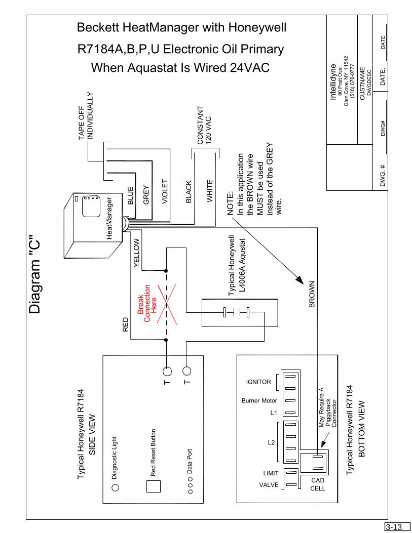
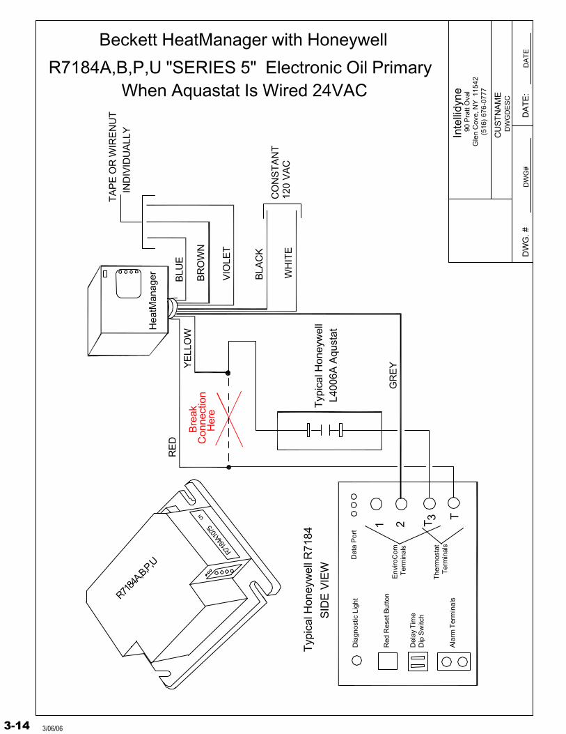
Beckett HeatManager with Honeywell
R7184A,B,P,U Electronic Oil Primary
When Aquastat Is Wired 24VACT
ypic
al H
oney
wel
l R71
84
SID
E V
IEW
BO
TT
OM
VIE
W
Typ
ical
Hon
eyw
ell R
7184
Dia
gnos
tic L
ight
Red
Res
et B
utto
n
Dat
a P
ort
Typ
ical
Hon
eyw
ell
TT
L400
6A A
qust
at
IGNITOR
Burner Motor
L1
L2
LIMIT
VALVECADCELL
YE
LLO
W
RE
D Con
nect
ion
Bre
ak
Her
e
BR
OW
N
BLA
CK
WH
ITE
CO
NS
TA
NT
120
VA
C
May
Req
uire
AP
iggy
back
Con
nect
or
Dia
gram
"C
" Hea
tMan
ager
NO
TE
:In
this
app
licat
ion
the
BR
OW
N w
ireM
US
T b
e us
ed
inst
ead
of th
e G
RE
Yw
ire.
3-13
Inte
llidy
ne
DW
G. #
DW
GD
ES
C
DW
G#
DA
TE
:D
AT
E
90 P
ratt
Ova
lG
len
Cov
e, N
Y 1
1542
(516
) 67
6-07
77
CU
ST
NA
ME
IND
IVID
UA
LLY
TA
PE
OR
WIR
EN
UT
BLU
E
VIO
LET
Beckett HeatManager with Honeywell
R7184A,B,P,U "SERIES 5" Electronic Oil Primary
Typ
ical
Hon
eyw
ell R
7184
SID
E V
IEW
Dia
gnos
tic L
ight
Red
Res
et B
utto
n
Dat
a P
ort
Typ
ical
Hon
eyw
ell
1
L400
6A A
qust
at
YE
LLO
W
RE
D Con
nect
ion
Bre
ak
Her
eB
RO
WN
BLA
CK
WH
ITE
CO
NS
TA
NT
120
VA
C
TA
larm
Ter
min
als
Del
ay T
ime
Dip
Sw
itch
GR
EY
When Aquastat Is Wired 24VAC
Hea
tMan
ager
Env
iroC
omT
erm
inal
s2
The
rmos
tat
Ter
min
als
R718
4A10
75
R7184
A,B,P,
U
5 3T
3-14 3/06/06
Inte
llid
yne
DW
G. #
DW
GD
ES
C
DW
G#
DA
TE
:D
AT
E
90 P
ratt
Ova
lG
len
Co
ve, N
Y 1
1542
(516
) 67
6-07
77
CU
STN
AM
E
HeatManager
L2L1T
TVAC
120
N
H
ZC
ZR
C1
B2C2
B1F F
DIF
Blue
Grey
Violet
TapeOff
Individually
Black
White
Brown
LHOI
BB
Yellow
Red
Safety Switch
Reset Button
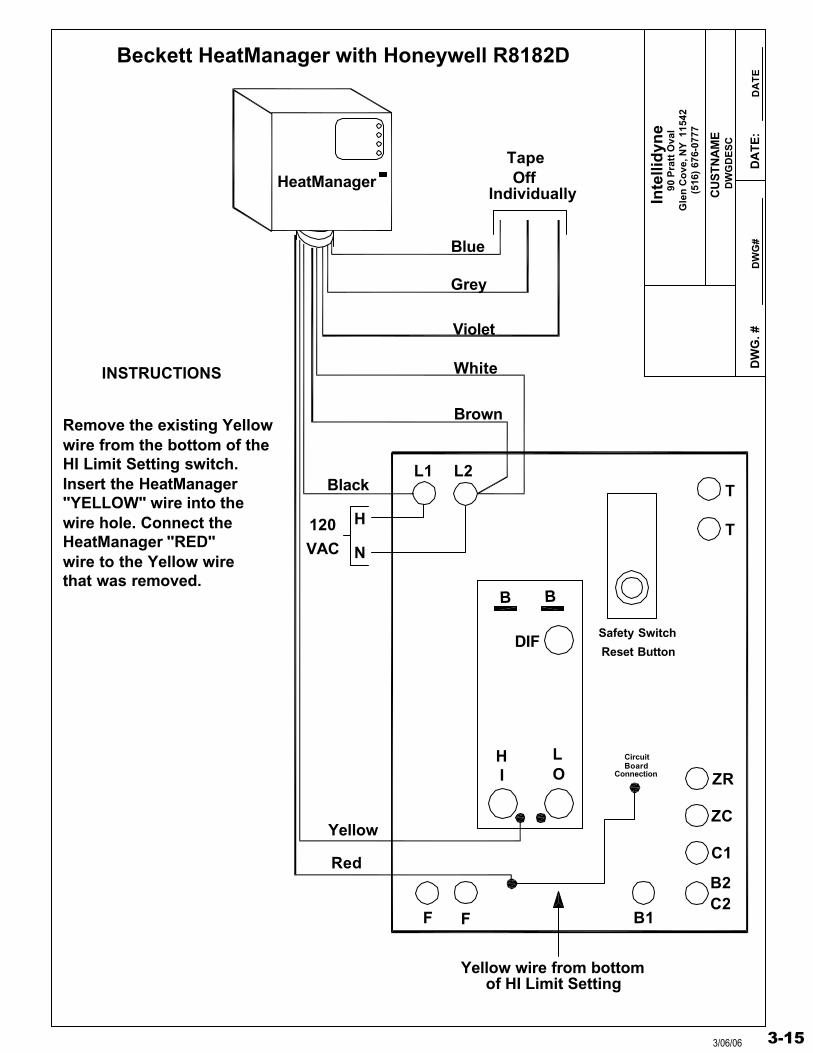
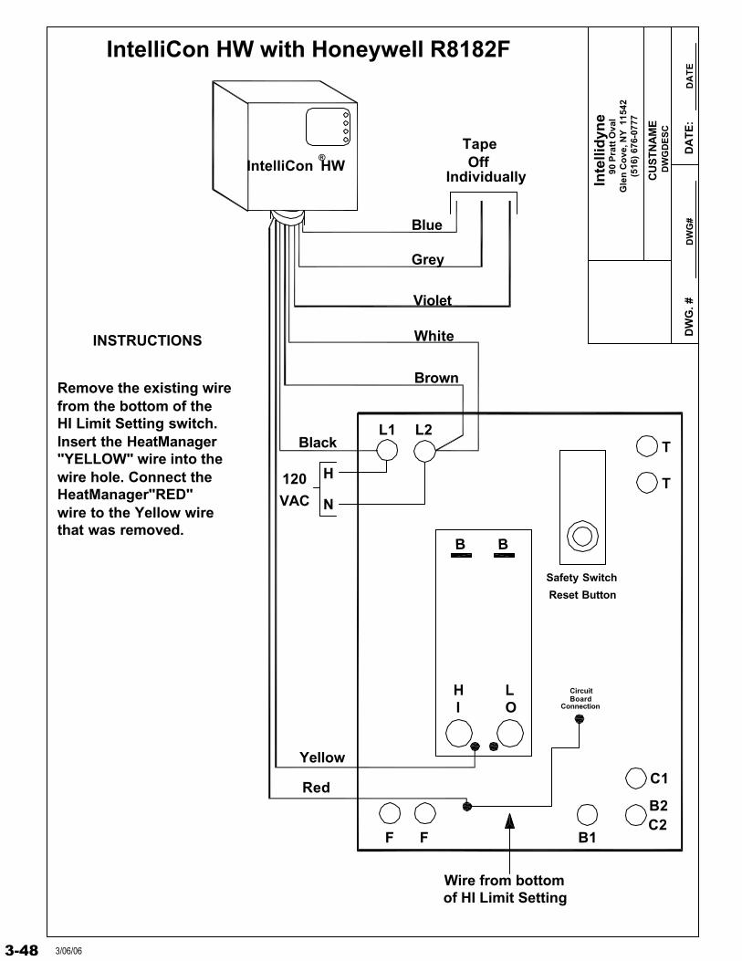
Remove the existing Yellow wire from the bottom of theHI Limit Setting switch.Insert the HeatManager"YELLOW" wire into the wire hole. Connect theHeatManager "RED"wire to the Yellow wirethat was removed.
INSTRUCTIONS
Yellow wire from bottomof HI Limit Setting
CircuitBoard
Connection
Beckett HeatManager with Honeywell R8182D
3-153/06/06
Inte
llid
yne
DW
G. #
DW
GD
ES
C
DW
G#
DA
TE
:D
AT
E
90 P
ratt
Ova
lG
len
Co
ve, N
Y 1
1542
(516
) 67
6-07
77
CU
STN
AM
E
HeatManager
L2L1T
TVAC
120
N
H
ZC
ZR
C1
B2C2
B1F F
Blue
Grey
Violet
TapeOff
Individually
Black
White
Brown
Yellow
Red
Safety Switch
Reset Button
INSTRUCTIONS
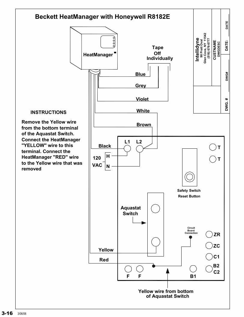
Yellow wire from bottomof Aquastat Switch
CircuitBoard
Connection
Beckett HeatManager with Honeywell R8182E
Remove the Yellow wirefrom the bottom terminalof the Aquastat Switch.Connect the HeatManager"YELLOW" wire to thisterminal. Connect theHeatManager "RED" wireto the Yellow wire that wasremoved
AquastatSwitch
3-16 3/06/06
Inte
llid
yne
DW
G. #
DW
GD
ES
C
DW
G#
DA
TE
:D
AT
E
90 P
ratt
Ova
lG
len
Co
ve, N
Y 1
1542
(516
) 67
6-07
77
CU
STN
AM
E
HeatManager
L2L1T
TVAC
120
N
H
C1
B2C2
B1F F
Blue
Grey
Violet
TapeOff
Individually
Black
White
Brown
LHOI
BB
Yellow
Red
Safety SwitchReset Button
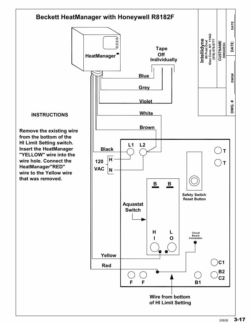
Remove the existing wirefrom the bottom of theHI Limit Setting switch.Insert the HeatManager"YELLOW" wire into the wire hole. Connect theHeatManager"RED"wire to the Yellow wirethat was removed.
INSTRUCTIONS
Wire from bottomof HI Limit Setting
CircuitBoard
Connection
Beckett HeatManager with Honeywell R8182F
AquastatSwitch
3-173/06/06
Inte
llid
yne
DW
G. #
DW
GD
ES
C
DW
G#
DA
TE
:D
AT
E
90 P
ratt
Ova
lG
len
Co
ve, N
Y 1
1542
(516
) 67
6-07
77
CU
STN
AM
E
Hea
tMan
ager
EY
E
RE
D
VIO
LE
T
BR
OW
N
BL
UE
CE
LL
CA
D
YE
LL
OW
GR
EY
OP
ER
AT
ING
AQ
UA
ST
AT
TT
YP
ICA
L
BL
AC
K
WH
ITE
T F F
HO
NE
YW
EL
LR
8184
G,K
,L o
r M
TA
PE
OF
FIN
DIV
IDU
AL
LY
BL
AC
K
WH
ITE
OR
AN
GE
120V
AC
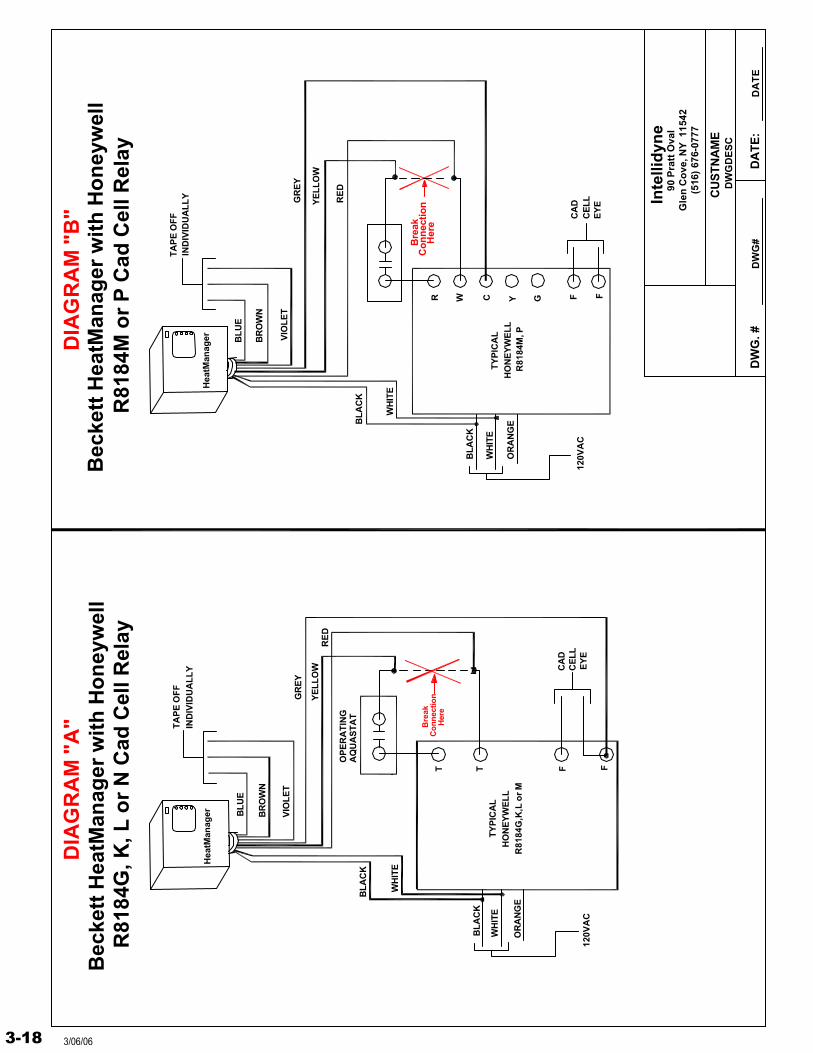
Bec
kett
Hea
tMan
ager
wit
h H
on
eyw
ell
R81
84G
, K, L
or
N C
ad C
ell R
elay
Bre
akC
on
nec
tion
Her
e
F FGYCWR
Hea
tMan
ager
GR
EY
BR
OW
N
BL
UE
VIO
LE
T
TA
PE
OF
FIN
DIV
IDU
AL
LY
BL
AC
K
WH
ITE
BL
AC
K
WH
ITE
OR
AN
GE
120V
AC
TY
PIC
AL
HO
NE
YW
EL
LR
8184
M, P
Co
nn
ectio
nB
reak
Her
e
YE
LL
OW
RE
D
CA
DC
EL
LE
YE
Bec
kett
Hea
tMan
ager
wit
h H
on
eyw
ell
R81
84M
or
P C
ad C
ell R
elay
DIA
GR
AM
"A
"D
IAG
RA
M "
B"
3-18 3/06/06
Inte
llid
yne
DW
G. #
DW
GD
ES
C
DW
G#
DA
TE
:D
AT
E
90 P
ratt
Ova
lG
len
Cov
e, N
Y 1
1542
(516
) 67
6-07
77
CU
ST
NA
ME
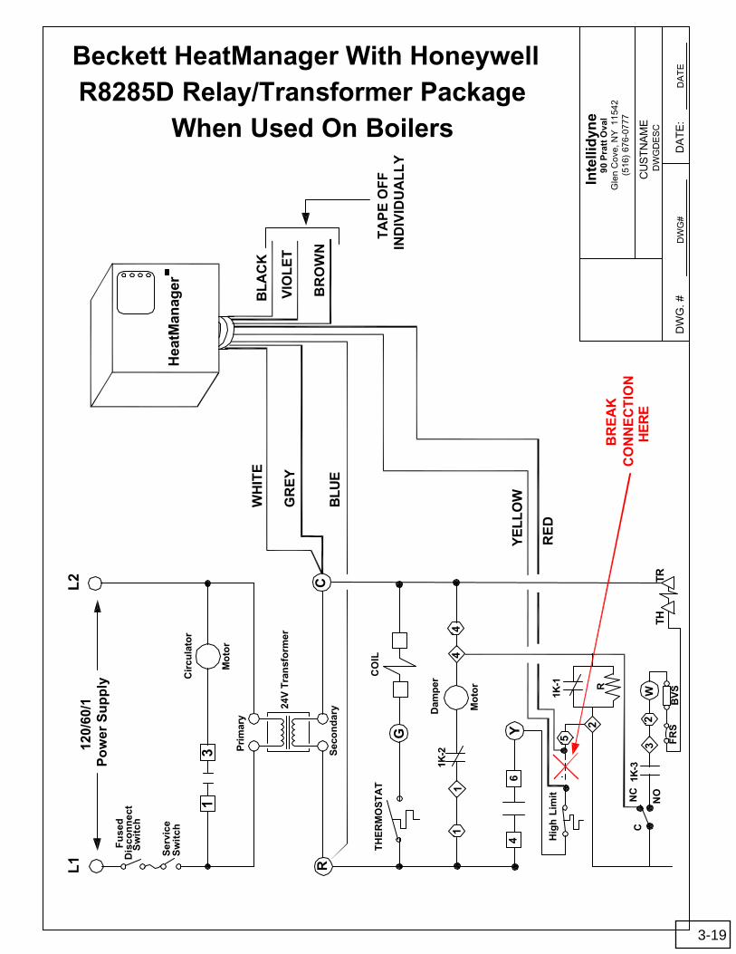
Hea
tMan
ager
L1
L2
120/
60/1
Po
wer
Su
pp
lyF
use
dD
isco
nn
ect
Sw
itch
Ser
vice
Sw
itch
13
Cir
cula
tor
Mo
tor
Pri
mar
y
Sec
on
dar
y24V
Tra
nsf
orm
er
RC
TH
ER
MO
ST
AT
G
CO
IL
11
1K-2
Dam
per
Mo
tor
44
46
Y
Hig
h L
imit
2
1K-1 R
NC
C
NO
1K-3
32
WTR
THF
RS
BV
S
WH
ITE
GR
EY
BLU
E
5
YE
LL
OW
RE
D
BL
AC
K
VIO
LE
T
BR
OW
N
TA
PE
OF
FIN
DIV
IDU
AL
LY
CO
NN
EC
TIO
NB
RE
AK
HE
RE
Beckett HeatManager With HoneywellR8285D Relay/Transformer Package
When Used On Boilers
3-19
Inte
llid
yne
DW
G. #
DW
GD
ES
C
DW
G#
DA
TE
:D
AT
E
90 P
ratt
Ova
lG
len
Co
ve, N
Y 1
1542
(516
) 67
6-07
77
CU
STN
AM
E
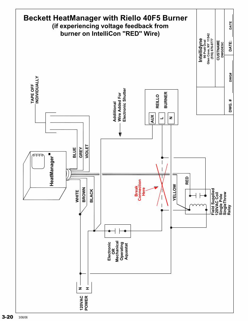
Beckett HeatManager with Riello 40F5 Burner(if experiencing voltage feedback from
burner on IntelliCon "RED" Wire)
Op
erat
ing
Aq
uas
tat
Bre
akC
on
nec
tio
nH
ere
120V
AC
PO
WE
R
N H
YE
LL
OW
BL
UE
WH
ITE
GR
EY
BL
AC
K
RE
D
VIO
LE
TB
RO
WN
TA
PE
OF
FIN
DIV
IDU
AL
LY
RE
ILLO
BU
RN
ER
Ad
diit
ion
alW
ire
Ad
ded
Fo
rE
lect
ron
ic S
hu
tter
NL
AU
X
Hea
tMan
ager
Fie
ld S
up
plie
d
Rel
ayS
ing
leT
hro
w
120V
AC
Co
ilS
ing
le P
ole
Mec
han
ical
Ele
ctro
nic
OR
3-20 3/06/06
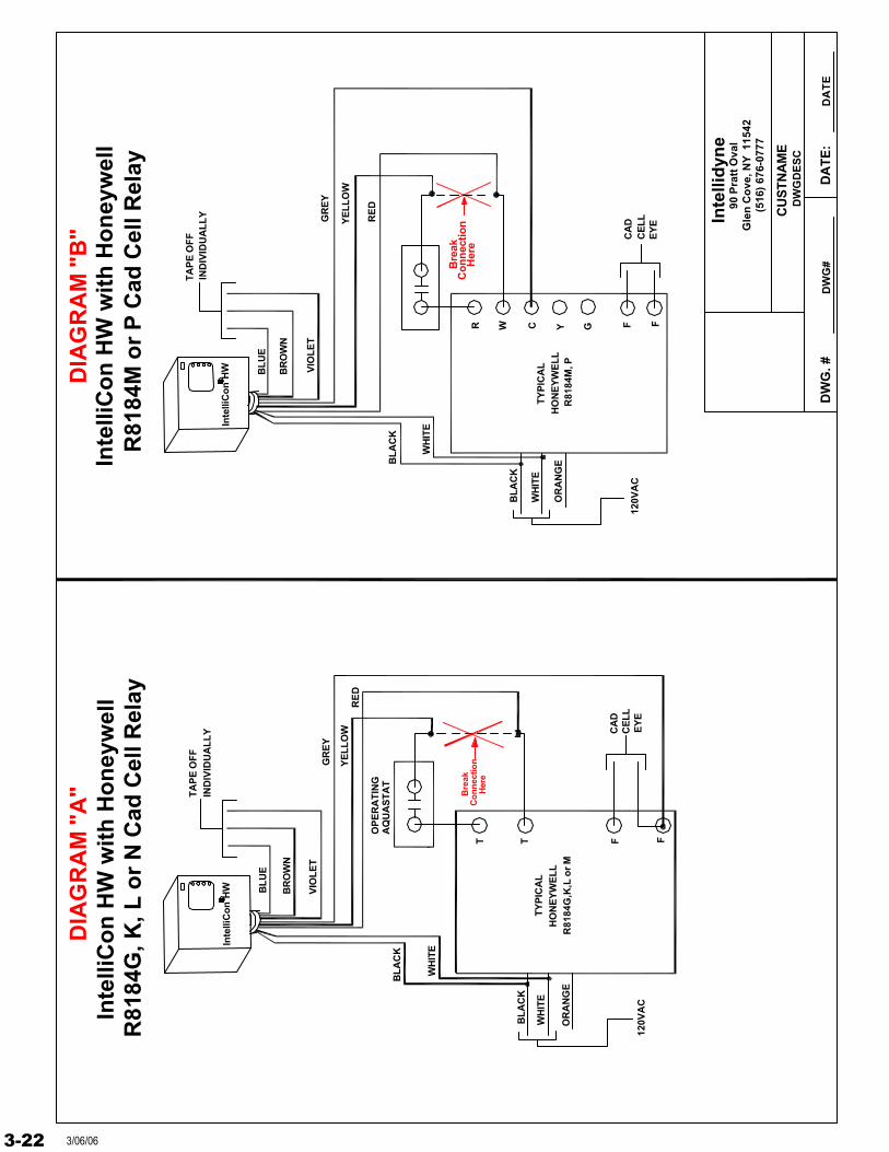
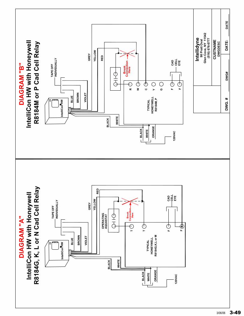
Wiring the IntelliCon® HW or LCH with A Cad Cell Relay
A boiler with the operating limit control (aqua-stat) wired to “T T” on the cad cell relay does not have to be rewired to accommodate the installation of the Model HW or LCH even though the internal transformer of the cad cell relay is not accessible for 24vac control wiring purposes.
DO NOT connect the HW or LCH control circuit at the orange lead on the cad cell relay as the burner will go off on “safety”. Wiring the HW or LCH control circuit at the black lead of the cad cell relay will remove power to the cad cell relay transformer.
If the “TT” terminals have a “jumper” across them, then the operating aqua-stat is line voltage and the HW or LCH can be wired 115vac for the power and the control circuit.
Below are the factory authorized wiring diagrams to accomplish the installation:
Diagram “A”: Honeywell R8184 G, K, L, N
Diagram “B”: Honeywell R8184 M, P
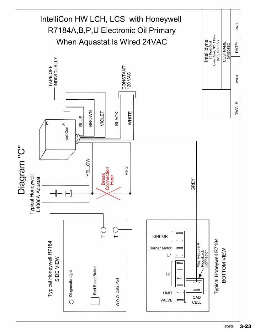
Diagram “C”: Honeywell R7184 A, B, P, U
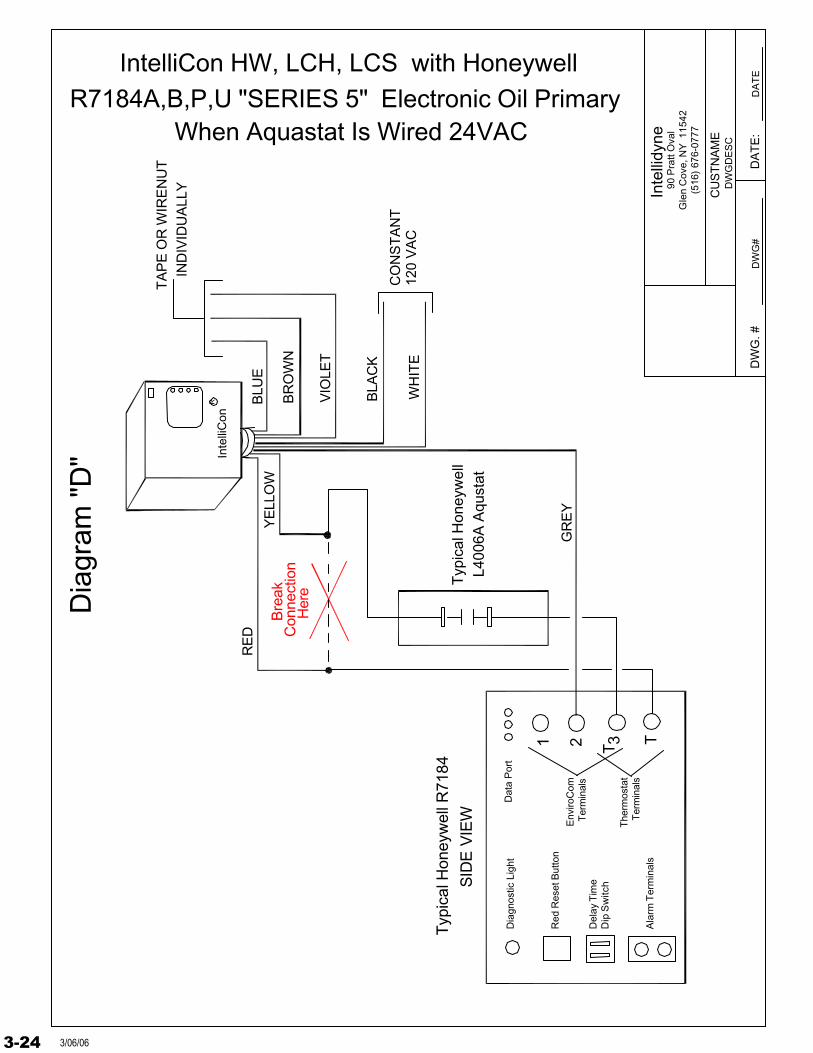
Diagram “D”: Honeywell R7184 A, B, P, U, “REVISION 5”
3-213/06/06
Inte
llid
yne
DW
G. #
DW
GD
ES
C
DW
G#
DA
TE
:D
AT
E
90 P
ratt
Ova
lG
len
Co
ve, N
Y 1
1542
(516
) 67
6-07
77
CU
STN
AM
E
Inte
lliC
on
HW
EY
E
RE
D
VIO
LE
T
BR
OW
N
BL
UE
CE
LL
CA
D
YE
LL
OW
GR
EY
OP
ER
AT
ING
AQ
UA
ST
AT
TT
YP
ICA
L
BL
AC
K
WH
ITE
T F F
HO
NE
YW
EL
LR
8184
G,K
,L o
r M
TA
PE
OF
FIN
DIV
IDU
AL
LY
BL
AC
K
WH
ITE
OR
AN
GE
120V
AC
Inte
lliC
on
HW
wit
h H
on
eyw
ell
R81
84G
, K, L
or
N C
ad C
ell R
elay
Bre
akC
on
nec
tion
Her
e
F FGYCWR
Inte
lliC
on
HW
GR
EY
BR
OW
N
BL
UE
VIO
LE
T
TA
PE
OF
FIN
DIV
IDU
AL
LY
BL
AC
K
WH
ITE
BL
AC
K
WH
ITE
OR
AN
GE
120V
AC
TY
PIC
AL
HO
NE
YW
EL
LR
8184
M, P
Co
nn
ectio
nB
reak
Her
e
YE
LL
OW
RE
D
CA
DC
EL
LE
YE
Inte
lliC
on
HW
wit
h H
on
eyw
ell
R81
84M
or
P C
ad C
ell R
elay
DIA
GR
AM
"A
"D
IAG
RA
M "
B"
3-22 3/06/06
Inte
llidy
ne
DW
G. #
DW
GD
ES
C
DW
G#
DA
TE
:D
AT
E
90 P
ratt
Ova
lG
len
Cov
e, N
Y 1
1542
(516
) 67
6-07
77
CU
ST
NA
ME
IND
IVID
UA
LLY
TA
PE
OF
F
BLU
E
VIO
LET
BR
OW
N
IntelliCon HW LCH, LCS with HoneywellR7184A,B,P,U Electronic Oil Primary
When Aquastat Is Wired 24VACT
ypic
al H
oney
wel
l R71
84
SID
E V
IEW
BO
TT
OM
VIE
W
Typ
ical
Hon
eyw
ell R
7184
Dia
gnos
tic L
ight
Red
Res
et B
utto
n
Dat
a P
ort
Typ
ical
Hon
eyw
ell
TT
L400
6A A
qust
at
IGNITOR
Burner Motor
L1
L2
LIMIT
VALVECADCELL
YE
LLO
W
RE
D
Con
nect
ion
Bre
ak
Her
e
GR
EY
BLA
CK
WH
ITE
CO
NS
TA
NT
120
VA
C
May
Req
uire
AP
iggy
back
Con
nect
or
Inte
lliC
onR
Dia
gram
"C
"
3-233/06/06
Inte
llidy
ne
DW
G. #
DW
GD
ES
C
DW
G#
DA
TE
:D
AT
E
90 P
ratt
Ova
lG
len
Cov
e, N
Y 1
1542
(516
) 67
6-07
77
CU
ST
NA
ME
IND
IVID
UA
LLY
TA
PE
OR
WIR
EN
UT
BLU
E
VIO
LET
Typ
ical
Hon
eyw
ell R
7184
SID
E V
IEW
Dia
gnos
tic L
ight
Red
Res
et B
utto
n
Dat
a P
ort
Typ
ical
Hon
eyw
ell
T1
L400
6A A
qust
at
YE
LLO
W
RE
D Con
nect
ion
Bre
ak
Her
eB
RO
WN
BLA
CK
WH
ITE
CO
NS
TA
NT
120
VA
C
2 TA
larm
Ter
min
als
Del
ay T
ime
Dip
Sw
itch
GR
EY
Env
iroC
omT
erm
inal
s
3T
herm
osta
tT
erm
inal
s
When Aquastat Is Wired 24VACElectronic Oil Primary
IntelliCon HW, LCH, LCS with HoneywellR7184A,B,P,U "SERIES 5"
Inte
lliC
onR
Dia
gram
"D
"
3-24 3/06/06
3 21
3-25
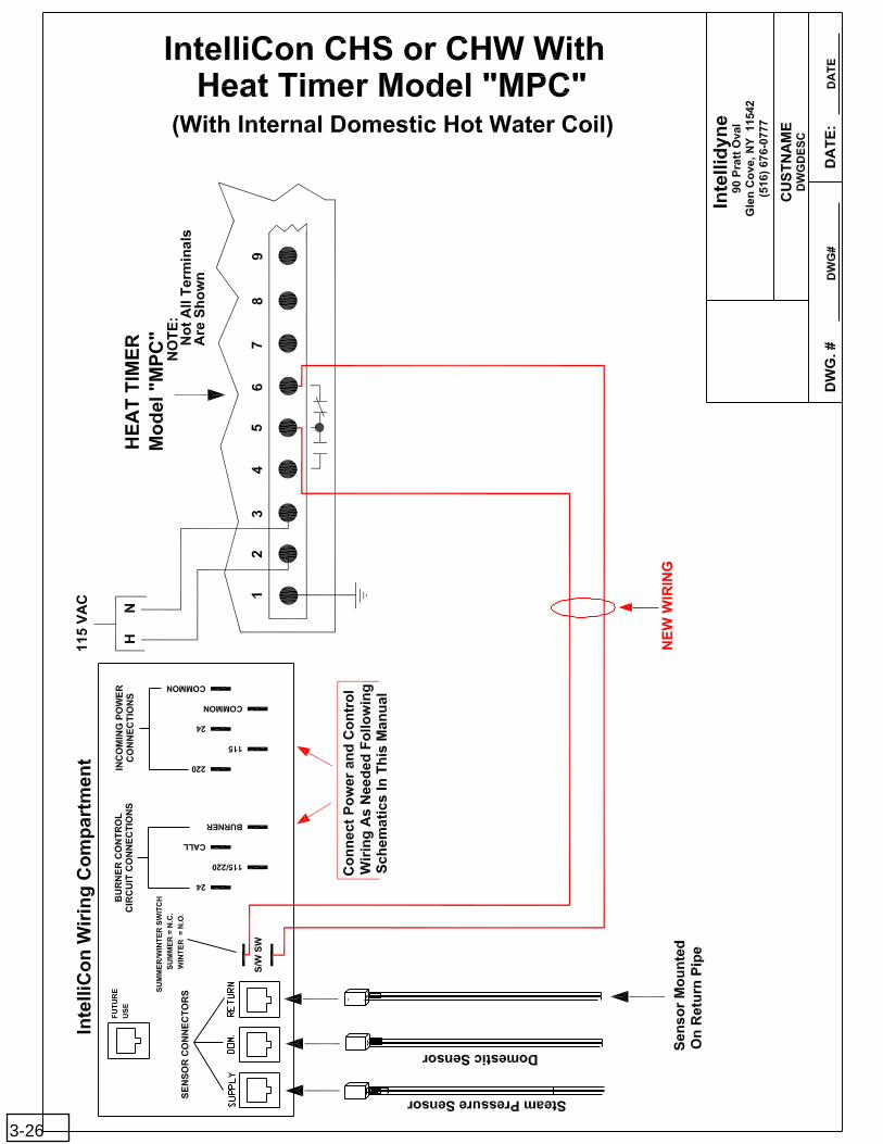
3-26
Inte
llid
yne
DW
G. #
DW
GD
ES
C
DW
G#
DA
TE
:D
AT
E
90 P
ratt
Ova
lG
len
Co
ve, N
Y 1
1542
(516
) 67
6-07
77
CU
STN
AM
E
Yel
low
Bla
ck
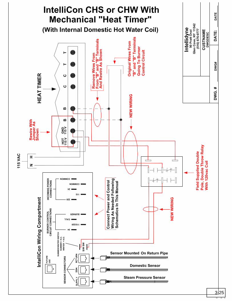
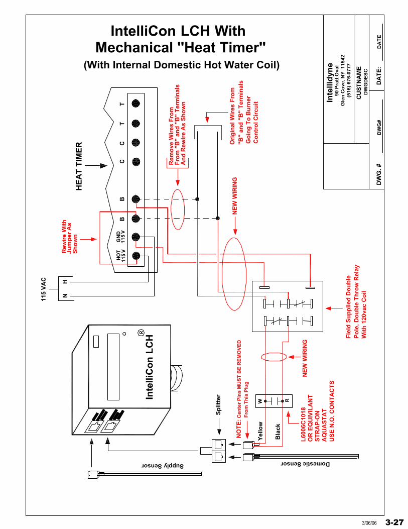
IntelliCon LCH With Mechanical "Heat Timer"
CC
BB
HO
TG
ND
115
VT
T11
5 V
HN115
VA
C
Rew
ire
With
Jum
per
As
Sh
ow
n
Rem
ove
Wir
es F
rom
Fro
m "
B"
and
"B
" T
erm
inal
sA
nd
Rew
ire
As
Sh
ow
n
Fie
ld S
up
plie
d D
ou
ble
Po
le, D
ou
ble
Th
row
Rel
ay
(With Internal Domestic Hot Water Coil)H
EA
T T
IME
R Go
ing
To
Bu
rner
Co
ntr
ol C
ircu
it
Wit
h 1
20va
c C
oil
Ori
gin
al W
ires
Fro
m"B
" an
d "
B"
Ter
min
als
NE
W W
IRIN
G
NE
W W
IRIN
G
Inte
lliC
on
LC
H
Supply Sensor
Sp
litte
r
Domestic Sensor
Cen
ter
Pin
s M
US
T B
E R
EM
OV
ED
Fro
m T
his
Plu
gN
OT
E:
US
E N
.O. C
ON
TA
CT
SA
QU
AS
TA
TS
TR
AP
-ON
OR
EQ
UIV
ILA
NT
L60
06C
1018
RW
3-273/06/06
Inte
llid
yne
DW
G. #
DW
GD
ES
C
DW
G#
DA
TE
:D
AT
E
90 P
ratt
Ova
lG
len
Co
ve, N
Y 1
1542
(516
) 67
6-07
77
CU
STN
AM
E
Yel
low
Bla
ckSp
litte
r
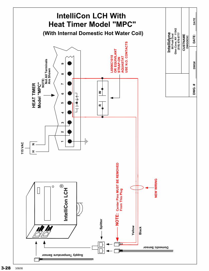
IntelliCon LCH WithHeat Timer Model "MPC"
Supply Temperature Sensor
Domestic Sensor
76
43
98
NH115
VA
C
(With Internal Domestic Hot Water Coil)H
EA
T T
IME
R
NE
W W
IRIN
G
Mo
del
"M
PC
"
12
5
No
t All
Ter
min
als
Are
Sh
ow
n
NO
TE
:
NO
TE
:F
rom
Th
is P
lug
Cen
ter
Pin
s M
US
T B
E R
EM
OV
ED
Inte
lliC
on
LC
H
L60
06C
1018
OR
EQ
UIV
ILA
NT
ST
RA
P-O
NA
QU
AS
TA
TU
SE
N.O
. CO
NT
AC
TS
RW
3-28 3/06/06
Inte
llid
yne
DW
G. #
DW
GD
ES
C
DW
G#
DA
TE
:D
AT
E
90 P
ratt
Ova
lG
len
Co
ve, N
Y 1
1542
(516
) 67
6-07
77
CU
STN
AM
E
Yel
low
Bla
ck
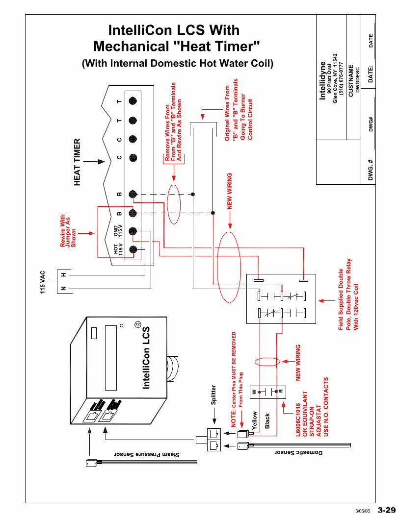
IntelliCon LCS With Mechanical "Heat Timer"
CC
BB
HO
TG
ND
115
VT
T11
5 V
HN115
VA
C
Rew
ire
With
Jum
per
As
Sh
ow
n
Rem
ove
Wir
es F
rom
Fro
m "
B"
and
"B
" T
erm
inal
sA
nd
Rew
ire
As
Sh
ow
n
Fie
ld S
up
plie
d D
ou
ble
Po
le, D
ou
ble
Th
row
Rel
ay
(With Internal Domestic Hot Water Coil)H
EA
T T
IME
R Go
ing
To
Bu
rner
Co
ntr
ol C
ircu
it
Wit
h 1
20va
c C
oil
Ori
gin
al W
ires
Fro
m"B
" an
d "
B"
Ter
min
als
NE
W W
IRIN
G
NE
W W
IRIN
G
Inte
lliC
on
LC
S
Steam Pressure Sensor
Sp
litte
r
Domestic Sensor
Cen
ter
Pin
s M
US
T B
E R
EM
OV
ED
Fro
m T
his
Plu
gN
OT
E:
RW
L60
06C
1018
OR
EQ
UIV
ILA
NT
ST
RA
P-O
NA
QU
AS
TA
TU
SE
N.O
. CO
NT
AC
TS
3-293/06/06

Inte
llid
yne
DW
G. #
DW
GD
ES
C
DW
G#
DA
TE
:D
AT
E
90 P
ratt
Ova
lG
len
Co
ve, N
Y 1
1542
(516
) 67
6-07
77
CU
STN
AM
E
Yel
low
Bla
ckSp
litte
r
IntelliCon LCS WithHeat Timer Model "MPC"
Steam Pressure Sensor
Domestic Sensor
76
43
98
NH115
VA
C
(With Internal Domestic Hot Water Coil)H
EA
T T
IME
R
NE
W W
IRIN
G
Mo
del
"M
PC
"
12
5
No
t All
Ter
min
als
Are
Sh
ow
n
NO
TE
:
NO
TE
:F
rom
Th
is P
lug
Cen
ter
Pin
s M
US
T B
E R
EM
OV
ED
Inte
lliC
on
LC
S
L60
06C
1018
OR
EQ
UIV
ILA
NT
ST
RA
P-O
NA
QU
AS
TA
TU
SE
N.O
. CO
NT
AC
TS
RW
3-30 3/06/06

Inte
llid
yne
DW
G. #
DW
GD
ES
C
DW
G#
DA
TE
:D
AT
E
90 P
ratt
Ova
lG
len
Co
ve, N
Y 1
1542
(516
) 67
6-07
77
CU
STN
AM
E
Inte
lliC
on
HW
R
IntelliCon HW with Riello 40F5 Burner(if experiencing voltage feedback from
burner on IntelliCon "RED" Wire)
Sin
gle
Po
le12
0VA
C C
oil
Sin
gle
Th
row
Rel
ay
Bre
akC
on
nec
tio
nH
ere
120V
AC
PO
WE
R
N H
YE
LL
OW
BL
UE
WH
ITE
GR
EY
BL
AC
K
RE
D
VIO
LE
TB
RO
WN
TA
PE
OF
FIN
DIV
IDU
AL
LY
RE
ILLO
BU
RN
ER
Ad
diit
ion
alW
ire
Ad
ded
Fo
rE
lect
ron
ic S
hu
tter
NL
AU
X
Fie
ld S
up
plie
d
Aq
uas
tat
Op
erat
ing
Mec
han
ical
Ele
ctro
nic
OR
3-313/06/06
Inte
llid
yne
DW
G. #
DW
GD
ES
C
DW
G#
DA
TE
:D
AT
E
90 P
ratt
Ova
lG
len
Co
ve, N
Y 1
1542
(516
) 67
6-07
77
CU
STN
AM
E
BLUE
GREY
VIOLET
INDIVIDUALLYTAPE OFF
B2 B1
HONEYWELL
TYPICAL
BLACK
BROWN
YELLOW
RED
TTL1 L2
C1
C2
WHITE
H
N
120
VAC
ZC
ZR
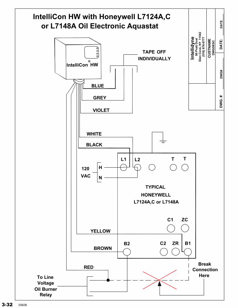
IntelliCon HW with Honeywell L7124A,C
IntelliCon HW®
L7124A,C or L7148A
or L7148A Oil Electronic Aquastat
ConnectionBreak
HereTo LineVoltage
Oil BurnerRelay
3-32 3/06/06
Inte
llid
yne
DW
G. #
DW
GD
ES
C
DW
G#
DA
TE
:D
AT
E
90 P
ratt
Ova
lG
len
Co
ve, N
Y 1
1542
(516
) 67
6-07
77
CU
STN
AM
E
BLUE
GREY
VIOLET
INDIVIDUALLYTAPE OFF
B2 B1
HONEYWELL
TYPICAL
BLACK
BROWN
YELLOW
RED
TTL1 L2
C1
C2
WHITE
H
N
120
VAC
ZC
ZR
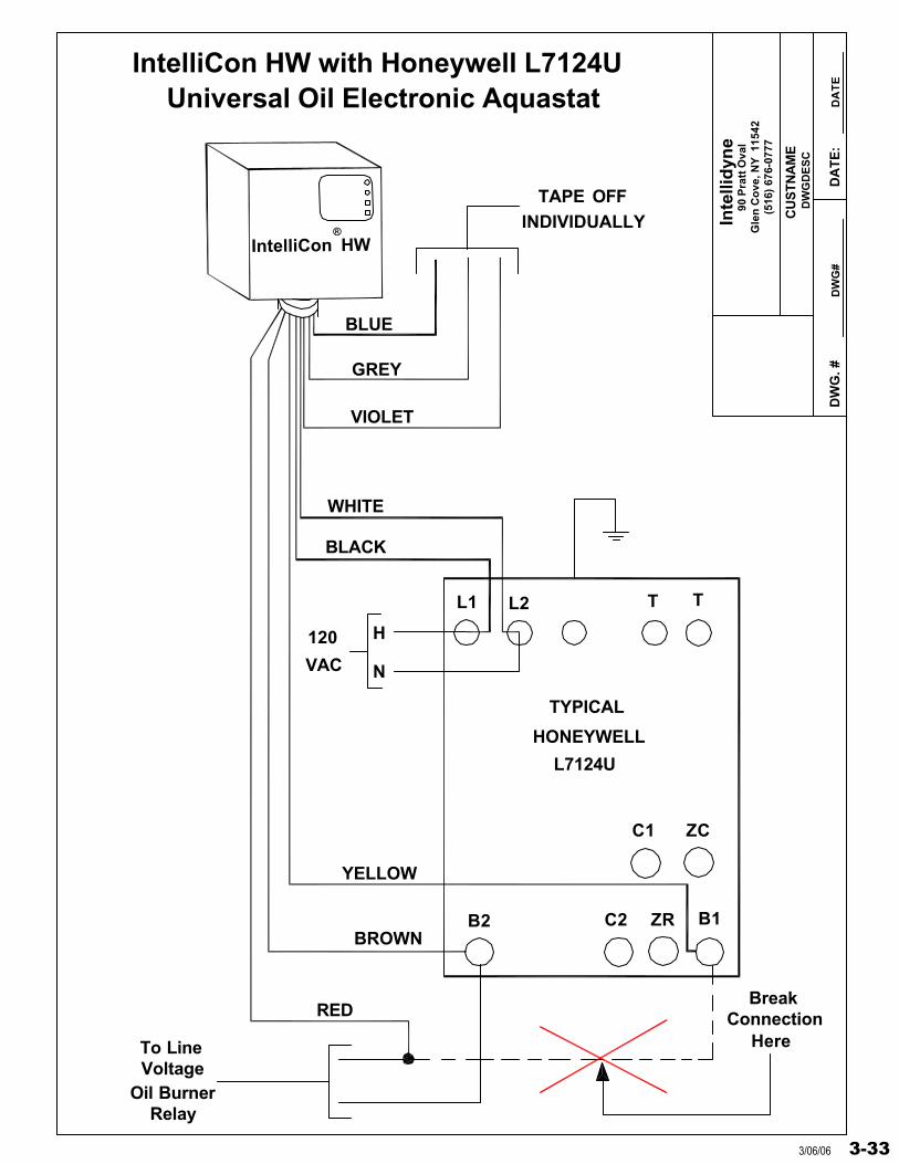
IntelliCon HW with Honeywell L7124U
IntelliCon HW®
L7124U
Universal Oil Electronic Aquastat
ConnectionBreak
HereTo LineVoltage
Oil BurnerRelay
3-333/06/06
Inte
llid
yne
DW
G. #
DW
GD
ES
C
DW
G#
DA
TE
:D
AT
E
90 P
ratt
Ova
lG
len
Co
ve, N
Y 1
1542
(516
) 67
6-07
77
CU
STN
AM
E
HO
NE
YW
EL
L
TY
PIC
AL
120
VA
C
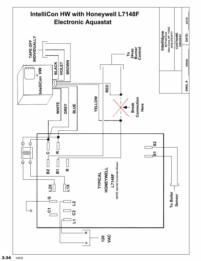
IntelliCon HW with Honeywell L7148F
Inte
lliC
on
HW
®
L71
48F
Electronic Aquastat
Co
nn
ecti
on
Bre
ak
Her
e
To
Bu
rner
24va
c
Co
ntr
ol
GC
1L
2X
L1X
B2
B1 R
C R
L1
C2
L2
S1
S2
NH
L1L2
CR
TA
PE
OF
FIN
DIV
IDU
AL
LY
WH
ITE
BLU
E
GR
EY
VIO
LE
T
BL
AC
K
BR
OW
N
RE
D
YE
LL
OW
NO
TE
: No
t All
Ter
min
als
Sh
ow
n
To
Bo
iler
Sen
sor
3-34 3/06/06
Inte
llid
yne
DW
G. #
D
AT
E:
90 P
ratt
Ova
lG
len
Co
ve, N
Y
1154
2(5
16)
676-
0777
CU
STN
AM
E
IND
IVID
UA
LL
YT
AP
E O
FF
GR
EY
BLU
E
BR
OW
N
WH
ITE
BL
AC
KV
IOL
ET
ZR
L1
L2
C2
B2
C1
B1
ZC
TY
PIC
AL
L72
24U
1
2
T 3
T
(No
t A
llT
erm
inal
sA
nd
Wir
ing
YE
LL
OW
RE
DS
ho
wn
)
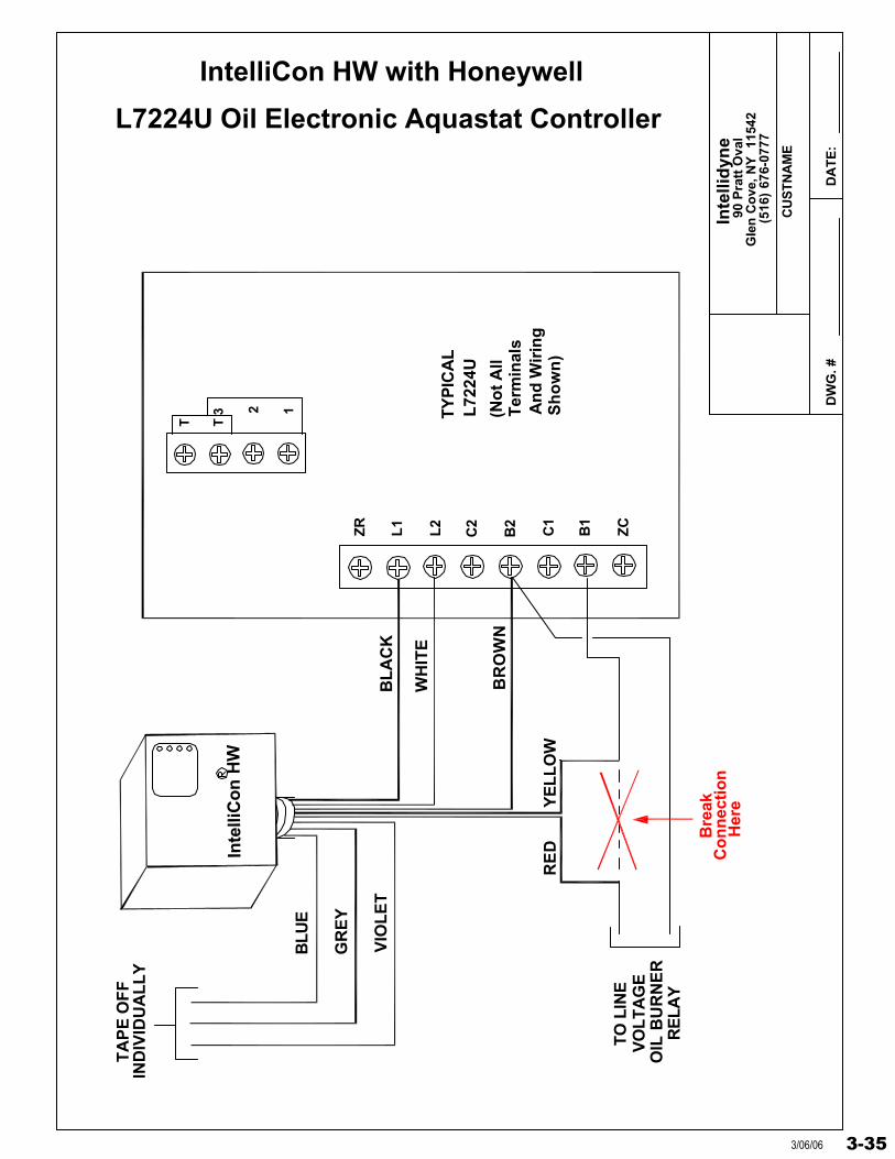
L7224U Oil Electronic Aquastat Controller
IntelliCon HW with Honeywell
Her
eC
on
nec
tio
nB
reak
TO
LIN
E
RE
LAY
OIL
BU
RN
ER
VO
LT
AG
E
Inte
lliC
on
HW
3-353/06/06
Inte
llid
yne
DW
G. #
DW
GD
ES
C
DW
G#
DA
TE
:
90 P
ratt
Ova
lG
len
Co
ve, N
Y 1
1542
(516
) 67
6-07
77
CU
STN
AM
E
L1 L2
G
VIOLET
GREY
BLUE
TAPE OFF
BREAK CONNECTION HERE
INDIVIDUALLY
TYPICALHONEYWELL L8124A,C
T T
B2
C1 ZR
C2 ZR B1
BLACK
WHITE
BROWN
TO LINEVOLTAGEOIL BURNERRELAY ORGAS VALVE
YELLOWRED
120VAC
IntelliCon HW with Honeywell L8124A,C
IntelliCon HWR
3-36 3/06/06
Inte
llid
yne
DW
G. #
DW
GD
ES
C
DW
G#
DA
TE
:D
AT
E
90 P
ratt
Ova
lG
len
Co
ve, N
Y 1
1542
(516
) 67
6-07
77
CU
STN
AM
E
TV T Z
BLUE
BROWN
VIOLET
INDIVIDUALLYTAPE OFF
L2L1
C2C1
B1 B2
L8124EHONEYWELL
TYPICAL
H N
120VAC
WHITE
BLACKGREY
YELLOW
RED
TO 24VACGAS VALVE
G
G
IntelliCon HW with HONEYWELL L8124E
IntelliCon HW ®
3-373/06/06
Inte
llid
yne
DW
G. #
DW
GD
ES
C
DW
G#
DA
TE
:D
AT
E
90 P
ratt
Ova
lG
len
Co
ve, N
Y 1
1542
(516
) 67
6-07
77
CU
STN
AM
E
TV T Z
BLUE
BROWN
VIOLET
INDIVIDUALLYTAPE OFF
L2L1
B2
C1B1 C2
L8124G,LHONEYWELL
TYPICAL
H N
120VAC
WHITE
BLACK
GREY
YELLOW
RED
G
GTO LINE VOLTAGE
OIL BURNER
RELAY ORGAS VALVE
IntelliCon HW with Honeywell L8124G,L
IntelliCon HW®
3-38 3/06/06
Inte
llid
yne
DW
G. #
DW
GD
ES
C
DW
G#
DA
TE
:D
AT
E
90 P
ratt
Ova
lG
len
Co
ve, N
Y 1
1542
(516
) 67
6-07
77
CU
STN
AM
E
BLUE
GREY
VIOLET
INDIVIDUALLYTAPE OFF
B2B1
L8148AHONEYWELL
TYPICAL
BLACK
BROWN
YELLOW
RED
TTG L1 L2
C1 C2
WHITE
G
H
N
120
VAC
TO LINE
VOLTAGE
OIL BURNER
RELAY OR
GAS VALVE
IntelliCon HW with Honeywell L8148A
IntelliCon HW®
3-393/06/06
Inte
llid
yne
DW
G. #
DW
GD
ES
C
DW
G#
DA
TE
:D
AT
E
90 P
ratt
Ova
lG
len
Co
ve, N
Y 1
1542
(516
) 67
6-07
77
CU
STN
AM
E
TV W T
Z
BLUE
BROWN
VIOLET
INDIVIDUALLYTAPE OFF
L2L1
C2C1
B1 B2
L8148EHONEYWELL
TYPICAL
H N
120VAC
WHITE
BLACK
GREY
YELLOW
RED
TO 24VACGAS VALVE
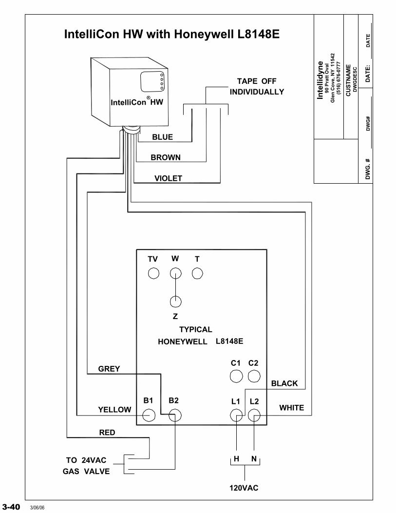
IntelliCon HW with Honeywell L8148E
IntelliCon HW®
3-40 3/06/06
Inte
llid
yne
DW
G. #
DW
GD
ES
C
DW
G#
DA
TE
:D
AT
E
90 P
ratt
Ova
lG
len
Co
ve, N
Y 1
1542
(516
) 67
6-07
77
CU
STN
AM
E
TV W T
Z
BLUE
BROWN
VIOLET
INDIVIDUALLYTAPE OFF
L2L1
C2C1
B1 B2
L8148JHONEYWELL
TYPICAL
H N
120VAC
WHITE
BLACKGREY
YELLOW
RED
TO 24VACGAS VALVE
GB3
G
TP
IntelliCon HW
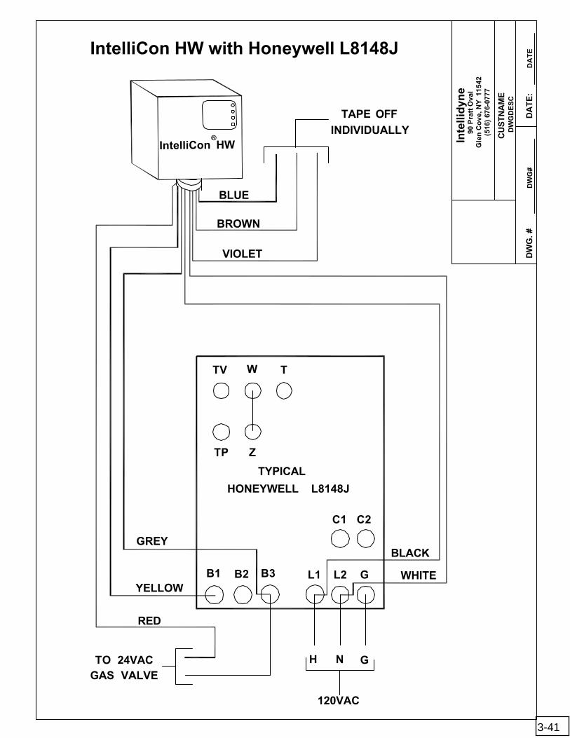
IntelliCon HW with Honeywell L8148J
®
3-41
Inte
llid
yne
DW
G. #
DW
GD
ES
C
DW
G#
DA
TE
:D
AT
E
90 P
ratt
Ova
lG
len
Co
ve, N
Y 1
1542
(516
) 67
6-07
77
CU
STN
AM
E
BLUE
GREY
VIOLET
INDIVIDUALLYTAPE OFF
B2 B1
L8151AHONEYWELL
TYPICAL
BLACK
BROWN
YELLOW
RED
TTG L1 L2
C1
C2
WHITE
G
H
N
120
VAC
TO LINEVOLTAGE
OIL BURNER
RELAY OR
GAS VALVE
ZC
ZR
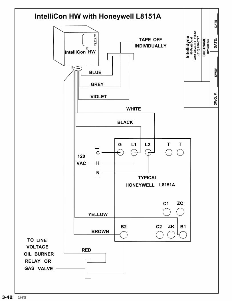
IntelliCon HW with Honeywell L8151A
IntelliCon HW®
3-42 3/06/06
Inte
llid
yne
DW
G. #
DW
GD
ES
C
DW
G#
DA
TE
:D
AT
E
90 P
ratt
Ova
lG
len
Co
ve, N
Y 1
1542
(516
) 67
6-07
77
CU
STN
AM
E
HO
NE
YW
EL
LT
YP
ICA
L
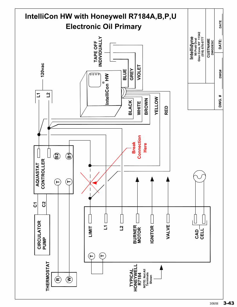
IntelliCon HW with Honeywell R7184A,B,P,U
Inte
lliC
on
HW
®
R71
84
Electronic Oil Primary
Co
nn
ecti
on
Bre
ak
Her
e
C1
B2
B1
L1C
2L2
TA
PE
OF
FIN
DIV
IDU
AL
LY
WH
ITE
BLU
E
GR
EY
VIO
LE
T
BL
AC
K
BR
OW
N
RE
D
YE
LL
OW
NO
TE
: No
t All
CA
DC
EL
L
TH
ER
MO
ST
AT
CIR
CU
LA
TO
RP
UM
P
R WTT
Ter
min
als
Sho
wn
AQ
UA
ST
AT
CO
NT
RO
LL
ER
T T
120v
ac
BU
RN
ER
L2L1
MO
TO
R
LIM
IT
VA
LV
E
IGN
ITO
R
3-433/06/06
Inte
llidy
ne
DW
G. #
DW
GD
ES
C
DW
G#
DA
TE
:D
AT
E
90 P
ratt
Ova
lG
len
Cov
e, N
Y 1
1542
(516
) 67
6-07
77
CU
ST
NA
ME
IND
IVID
UA
LLY
TA
PE
OR
WIR
EN
UT
BLU
E
VIO
LET
IntelliCon HW with Honeywell
R7184A,B,P,U "SERIES 5" Electronic Oil Primary
Typ
ical
Hon
eyw
ell R
7184
SID
E V
IEW
Dia
gnos
tic L
ight
Red
Res
et B
utto
n
Dat
a P
ort
Typ
ical
Hon
eyw
ell
TT
L400
6A A
qust
at
YE
LLO
W
RE
D Con
nect
ion
Bre
ak
Her
eB
RO
WN
BLA
CK
WH
ITE
CO
NS
TA
NT
120
VA
C
2 1A
larm
Ter
min
als
Del
ay T
ime
Dip
Sw
itch
GR
EY
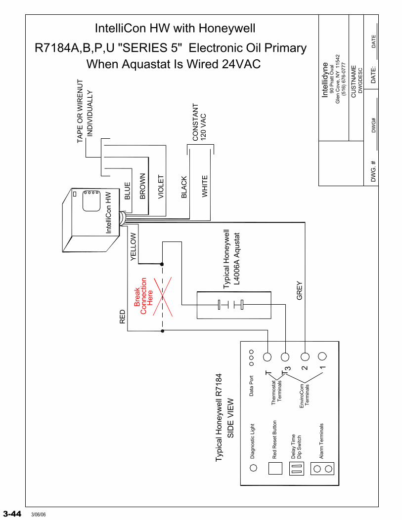
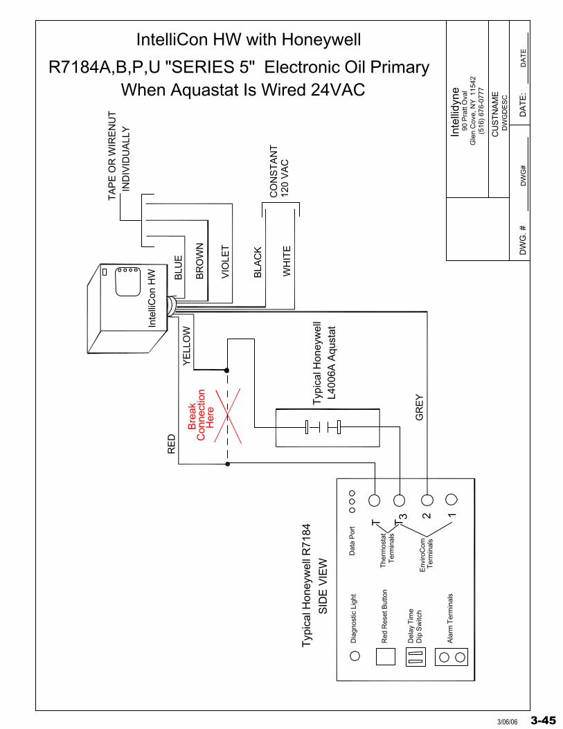
When Aquastat Is Wired 24VAC
Inte
lliC
on H
W
Env
iroC
omT
erm
inal
s
3
The
rmos
tat
Ter
min
als
3-44 3/06/06
Inte
llidy
ne
DW
G. #
DW
GD
ES
C
DW
G#
DA
TE
:D
AT
E
90 P
ratt
Ova
lG
len
Cov
e, N
Y 1
1542
(516
) 67
6-07
77
CU
ST
NA
ME
IND
IVID
UA
LLY
TA
PE
OR
WIR
EN
UT
BLU
E
VIO
LET
IntelliCon HW with Honeywell
R7184A,B,P,U "SERIES 5" Electronic Oil Primary
Typ
ical
Hon
eyw
ell R
7184
SID
E V
IEW
Dia
gnos
tic L
ight
Red
Res
et B
utto
n
Dat
a P
ort
Typ
ical
Hon
eyw
ell
TT
L400
6A A
qust
at
YE
LLO
W
RE
D Con
nect
ion
Bre
ak
Her
eB
RO
WN
BLA
CK
WH
ITE
CO
NS
TA
NT
120
VA
C
2 1A
larm
Ter
min
als
Del
ay T
ime
Dip
Sw
itch
GR
EY
When Aquastat Is Wired 24VAC
Inte
lliC
on H
W
Env
iroC
omT
erm
inal
s
3
The
rmos
tat
Ter
min
als
3-453/06/06
Inte
llid
yne
DW
G. #
DW
GD
ES
C
DW
G#
DA
TE
:D
AT
E
90 P
ratt
Ova
lG
len
Co
ve, N
Y 1
1542
(516
) 67
6-07
77
CU
STN
AM
E
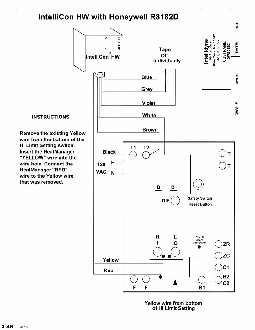
IntelliCon HW
L2L1T
TVAC
120
N
H
ZC
ZR
C1
B2C2
B1F F
DIF
Blue
Grey
Violet
TapeOff
Individually
Black
White
Brown
LHOI
BB
Yellow
Red
Safety Switch
Reset Button
Remove the existing Yellow wire from the bottom of theHI Limit Setting switch.Insert the HeatManager"YELLOW" wire into the wire hole. Connect theHeatManager "RED"wire to the Yellow wirethat was removed.
INSTRUCTIONS
Yellow wire from bottomof HI Limit Setting
CircuitBoard
Connection
IntelliCon HW with Honeywell R8182D
®
3-46 3/06/06
Inte
llid
yne
DW
G. #
DW
GD
ES
C
DW
G#
DA
TE
:D
AT
E
90 P
ratt
Ova
lG
len
Co
ve, N
Y 1
1542
(516
) 67
6-07
77
CU
STN
AM
E
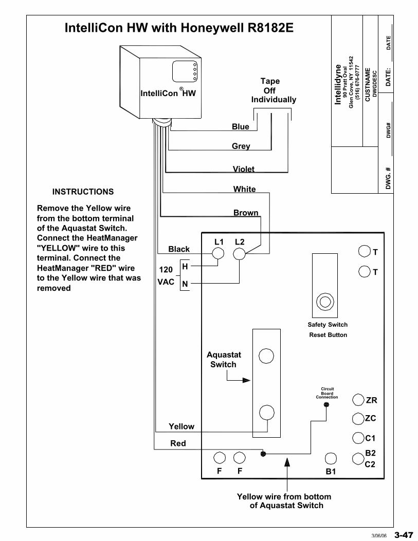
IntelliCon HW
L2L1T
TVAC
120
N
H
ZC
ZR
C1
B2C2
B1F F
Blue
Grey
Violet
TapeOff
Individually
Black
White
Brown
Yellow
Red
Safety Switch
Reset Button
INSTRUCTIONS
Yellow wire from bottomof Aquastat Switch
CircuitBoard
Connection
IntelliCon HW with Honeywell R8182E
Remove the Yellow wirefrom the bottom terminalof the Aquastat Switch.Connect the HeatManager"YELLOW" wire to thisterminal. Connect theHeatManager "RED" wireto the Yellow wire that wasremoved
AquastatSwitch
®
3-473/06/06
Inte
llid
yne
DW
G. #
DW
GD
ES
C
DW
G#
DA
TE
:D
AT
E
90 P
ratt
Ova
lG
len
Co
ve, N
Y 1
1542
(516
) 67
6-07
77
CU
STN
AM
E
IntelliCon HW
L2L1T
TVAC
120
N
H
C1
B2C2
B1F F
Blue
Grey
Violet
TapeOff
Individually
Black
White
Brown
LHOI
BB
Yellow
Red
Safety Switch
Reset Button
Remove the existing wirefrom the bottom of theHI Limit Setting switch.Insert the HeatManager"YELLOW" wire into the wire hole. Connect theHeatManager"RED"wire to the Yellow wirethat was removed.
INSTRUCTIONS
Wire from bottomof HI Limit Setting
CircuitBoard
Connection
IntelliCon HW with Honeywell R8182F
®
3-48 3/06/06
Inte
llid
yne
DW
G. #
DW
GD
ES
C
DW
G#
DA
TE
:D
AT
E
90 P
ratt
Ova
lG
len
Co
ve, N
Y 1
1542
(516
) 67
6-07
77
CU
STN
AM
E
Inte
lliC
on
HW
EY
E
RE
D
VIO
LE
T
BR
OW
N
BL
UE
CE
LL
CA
D
YE
LL
OW
GR
EY
OP
ER
AT
ING
AQ
UA
ST
AT
TT
YP
ICA
L
BL
AC
K
WH
ITE
T F F
HO
NE
YW
EL
LR
8184
G,K
,L o
r M
TA
PE
OF
FIN
DIV
IDU
AL
LY
BL
AC
K
WH
ITE
OR
AN
GE
120V
AC
Inte
lliC
on
HW
wit
h H
on
eyw
ell
R81
84G
, K, L
or
N C
ad C
ell R
elay
Bre
akC
on
nec
tion
Her
e
F FGYCWR
Inte
lliC
on
HW
GR
EY
BR
OW
N
BL
UE
VIO
LE
T
TA
PE
OF
FIN
DIV
IDU
AL
LY
BL
AC
K
WH
ITE
BL
AC
K
WH
ITE
OR
AN
GE
120V
AC
TY
PIC
AL
HO
NE
YW
EL
LR
8184
M, P
Co
nn
ectio
nB
reak
Her
e
YE
LL
OW
RE
D
CA
DC
EL
LE
YE
Inte
lliC
on
HW
wit
h H
on
eyw
ell
R81
84M
or
P C
ad C
ell R
elay
DIA
GR
AM
"A
"D
IAG
RA
M "
B"
3-493/06/06
Inte
llid
yne
DW
G. #
DW
GD
ES
C
DW
G#
DA
TE
:D
AT
E
90 P
ratt
Ova
lG
len
Cov
e, N
Y 1
1542
(516
) 67
6-07
77
CU
ST
NA
ME
Inte
lliC
on
HW
L1
L2
120/
60/1
Po
wer
Su
pp
lyF
use
dD
isco
nn
ect
Sw
itch
Ser
vice
Sw
itch
13
Cir
cula
tor
Mo
tor
Pri
mar
y
Sec
on
dar
y24V
Tra
nsf
orm
er
RC
TH
ER
MO
ST
AT
G
CO
IL
11
1K-2
Dam
per
Mo
tor
44
46
Y
Hig
h L
imit
2
1K-1 R
NC
C
NO
1K-3
32
WTR
THF
RS
BV
S
WH
ITE
GR
EY
BLU
E
5
YE
LL
OW
RE
D
BL
AC
K
VIO
LE
T
BR
OW
N
TA
PE
OF
FIN
DIV
IDU
AL
LY
CO
NN
EC
TIO
NB
RE
AK
HE
RE
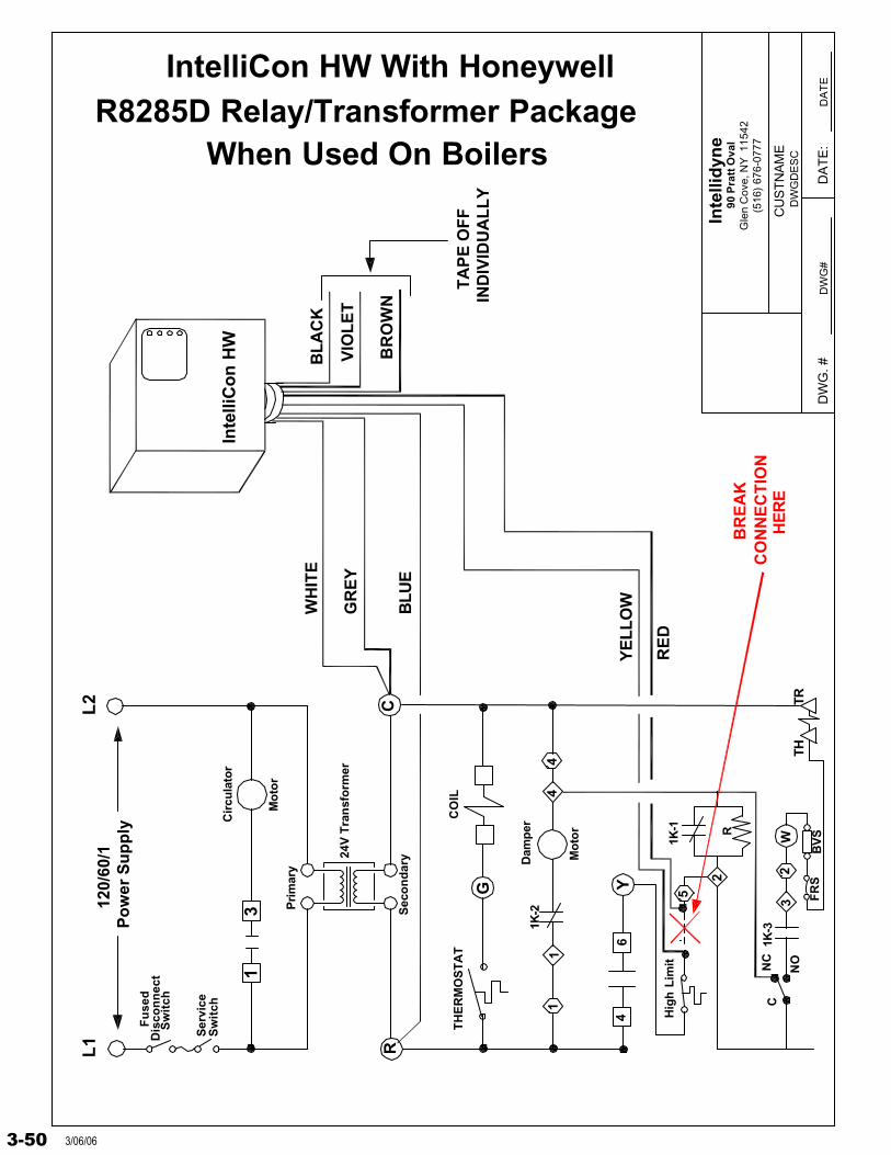
IntelliCon HW With HoneywellR8285D Relay/Transformer Package
When Used On Boilers
3-50 3/06/06
Inte
llid
yne
DW
G. #
DW
GD
ES
C
DW
G#
DA
TE
:D
AT
E
90 P
ratt
Ova
lG
len
Co
ve, N
Y 1
1542
(516
) 67
6-07
77
CU
STN
AM
E
Inte
lliC
on
HW
R
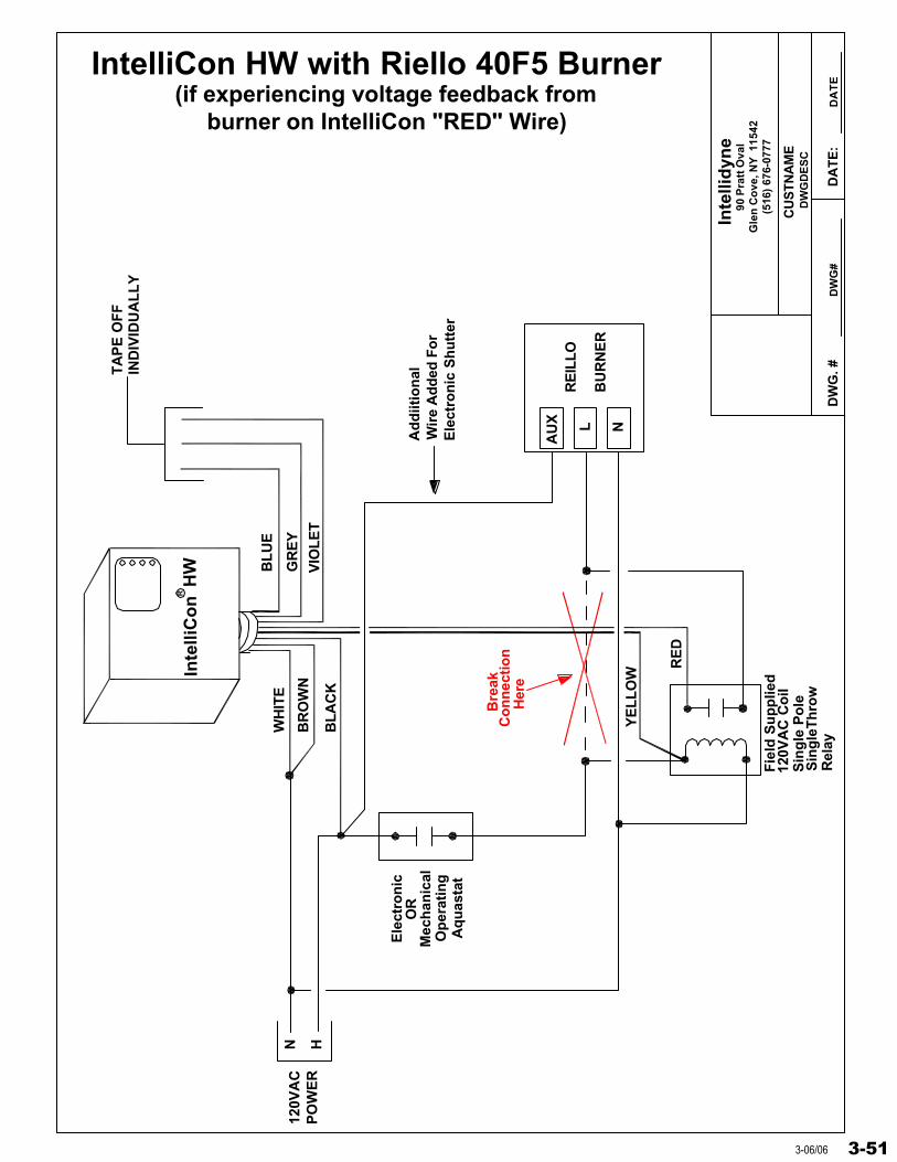
IntelliCon HW with Riello 40F5 Burner(if experiencing voltage feedback from
burner on IntelliCon "RED" Wire)
Sin
gle
Po
le12
0VA
C C
oil
Sin
gle
Th
row
Rel
ay
Bre
akC
on
nec
tio
nH
ere
120V
AC
PO
WE
R
N H
YE
LL
OW
BL
UE
WH
ITE
GR
EY
BL
AC
K
RE
D
VIO
LE
TB
RO
WN
TA
PE
OF
FIN
DIV
IDU
AL
LY
RE
ILLO
BU
RN
ER
Ad
diit
ion
alW
ire
Ad
ded
Fo
rE
lect
ron
ic S
hu
tter
NL
AU
X
Fie
ld S
up
plie
d
Aq
uas
tat
Op
erat
ing
Mec
han
ical
Ele
ctro
nic
OR
3-513-06/06
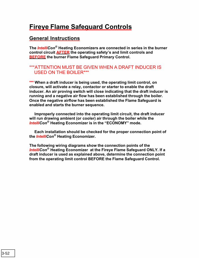
Fireye Flame Safeguard Controls
General Instructions
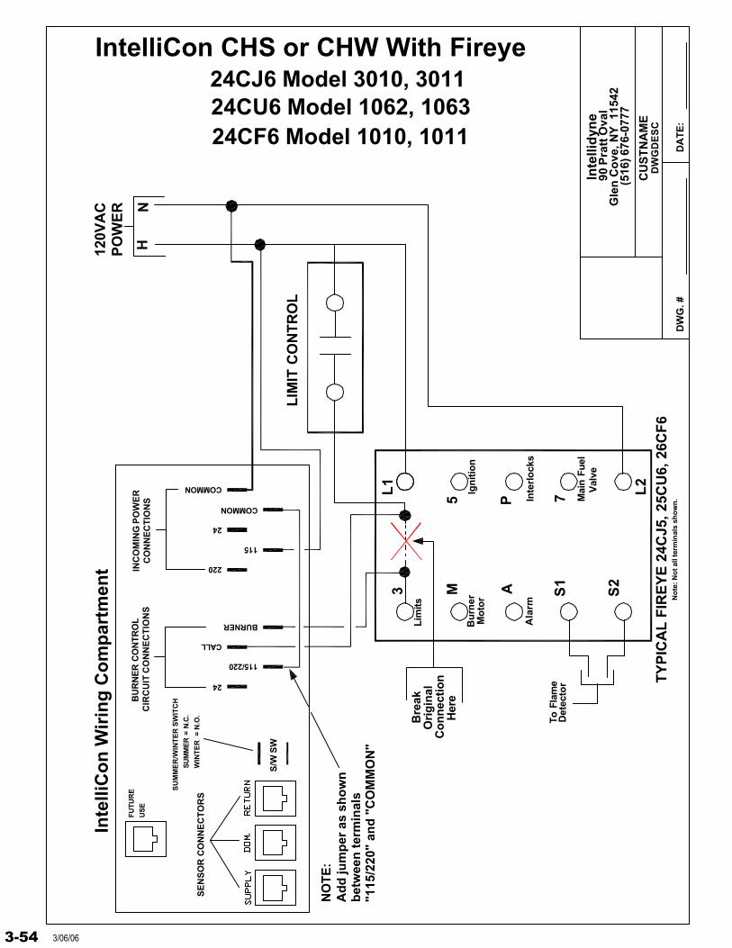
The IntelliCon® Heating Economizers are connected in series in the burner control circuit AFTER the operating safety’s and limit controls and BEFORE the burner Flame Safeguard Primary Control.
***ATTENTION MUST BE GIVEN WHEN A DRAFT INDUCER IS USED ON THE BOILER***
*** When a draft inducer is being used, the operating limit control, onclosure, will activate a relay, contactor or starter to enable the draft inducer. An air proving switch will close indicating that the draft inducer is running and a negative air flow has been established through the boiler. Once the negative airflow has been established the Flame Safeguard is enabled and starts the burner sequence.
Improperly connected into the operating limit circuit, the draft inducer will run drawing ambient (or cooler) air through the boiler while the IntelliCon® Heating Economizer is in the “ECONOMY” mode.
Each installation should be checked for the proper connection point of the IntelliCon® Heating Economizer.
The following wiring diagrams show the connection points of theIntelliCon® Heating Economizer at the Fireye Flame Safeguard ONLY. If a draft inducer is used as explained above, determine the connection point from the operating limit control BEFORE the Flame Safeguard Control.
3-52

Inte
llid
yne
DW
G. #
DW
GD
ES
C
DA
TE
:
90 P
ratt
Ova
lG
len
Co
ve, N
Y 1
1542
(516
) 676
-077
7
CU
ST
NA
ME
3 M A S1
S2
L1
5 P
L2
7
HN
120V
AC
PO
WE
R
LIM
IT C
ON
TR
OL
Bu
rner
Mo
tor
Lim
its
Ign
itio
n
Inte
rlo
cks
Mai
n Fu
elV
alve
To F
lam
eD
etec
tor
Bre
ak
Her
e
Ori
gin
alC
on
nec
tio
n
"115
/220
" an
d "
CO
MM
ON
"b
etw
een
ter
min
als
Ad
d ju
mp
er a
s sh
ow
nN
OT
E:
No
te: N
ot a
ll te
rmin
als
sho
wn
.
Ala
rm
TY
PIC
AL
FIR
EY
E 2
4CJ5
, 25C
U6,
26C
F6
IntelliCon CHS or CHW With Fireye
24CF6 Model 1010, 101124CU6 Model 1062, 106324CJ6 Model 3010, 3011
CIR
CU
IT C
ON
NE
CT
ION
SB
UR
NE
R C
ON
TRO
L
Inte
lliC
on
Wir
ing
Co
mp
artm
ent
115/220
SE
NS
OR
CO
NN
EC
TO
RS
S/W
SW
24
SU
MM
ER
/WIN
TE
R S
WIT
CH
WIN
TE
R =
N.O
.
SU
MM
ER
= N
.C.
FU
TU
RE
US
E
COMMON
CALL
BURNER
COMMON
115
220
24
CO
NN
EC
TIO
NS
INC
OM
ING
PO
WE
R
3-533/06/06
Inte
llid
yne
DW
G. #
DW
GD
ES
C
DA
TE
:
90 P
ratt
Ova
lG
len
Co
ve, N
Y 1
1542
(516
) 676
-077
7
CU
ST
NA
ME
3 M A S1
S2
L1
5 P
L2
7
HN
120V
AC
PO
WE
R
LIM
IT C
ON
TR
OL
Bu
rner
Mo
tor
Lim
its
Ign
itio
n
Inte
rlo
cks
Mai
n Fu
elV
alve
To F
lam
eD
etec
tor
Bre
ak
Her
e
Ori
gin
alC
on
nec
tio
n
"115
/220
" an
d "
CO
MM
ON
"b
etw
een
ter
min
als
Ad
d ju
mp
er a
s sh
ow
nN
OT
E:
No
te: N
ot a
ll te
rmin
als
sho
wn
.
Ala
rm
TY
PIC
AL
FIR
EY
E 2
4CJ5
, 25C
U6,
26C
F6
IntelliCon CHS or CHW With Fireye
24CF6 Model 1010, 101124CU6 Model 1062, 106324CJ6 Model 3010, 3011
CIR
CU
IT C
ON
NE
CT
ION
SB
UR
NE
R C
ON
TRO
L
Inte
lliC
on
Wir
ing
Co
mp
artm
ent
115/220
SE
NS
OR
CO
NN
EC
TO
RS
S/W
SW
24
SU
MM
ER
/WIN
TE
R S
WIT
CH
WIN
TE
R =
N.O
.
SU
MM
ER
= N
.C.
FU
TU
RE
US
E
COMMON
CALL
BURNER
COMMON
115
220
24
CO
NN
EC
TIO
NS
INC
OM
ING
PO
WE
R
3-54 3/06/06
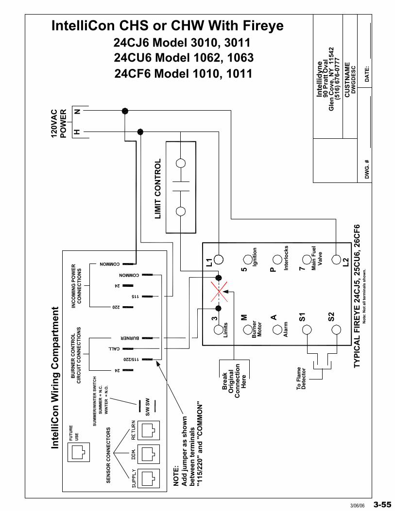
Inte
llid
yne
DW
G. #
DW
GD
ES
C
DA
TE
:
90 P
ratt
Ova
lG
len
Co
ve, N
Y 1
1542
(516
) 676
-077
7
CU
ST
NA
ME
3 M A S1
S2
L1
5 P
L2
7
HN
120V
AC
PO
WE
R
LIM
IT C
ON
TR
OL
Bu
rner
Mo
tor
Lim
its
Ign
itio
n
Inte
rlo
cks
Mai
n Fu
elV
alve
To F
lam
eD
etec
tor
Bre
ak
Her
e
Ori
gin
alC
on
nec
tio
n
"115
/220
" an
d "
CO
MM
ON
"b
etw
een
ter
min
als
Ad
d ju
mp
er a
s sh
ow
nN
OT
E:
No
te: N
ot a
ll te
rmin
als
sho
wn
.
Ala
rm
TY
PIC
AL
FIR
EY
E 2
4CJ5
, 25C
U6,
26C
F6
IntelliCon CHS or CHW With Fireye
24CF6 Model 1010, 101124CU6 Model 1062, 106324CJ6 Model 3010, 3011
CIR
CU
IT C
ON
NE
CT
ION
SB
UR
NE
R C
ON
TRO
L
Inte
lliC
on
Wir
ing
Co
mp
artm
ent
115/220
SE
NS
OR
CO
NN
EC
TO
RS
S/W
SW
24
SU
MM
ER
/WIN
TE
R S
WIT
CH
WIN
TE
R =
N.O
.
SU
MM
ER
= N
.C.
FU
TU
RE
US
E
COMMON
CALL
BURNER
COMMON
115
220
24
CO
NN
EC
TIO
NS
INC
OM
ING
PO
WE
R
3-553/06/06
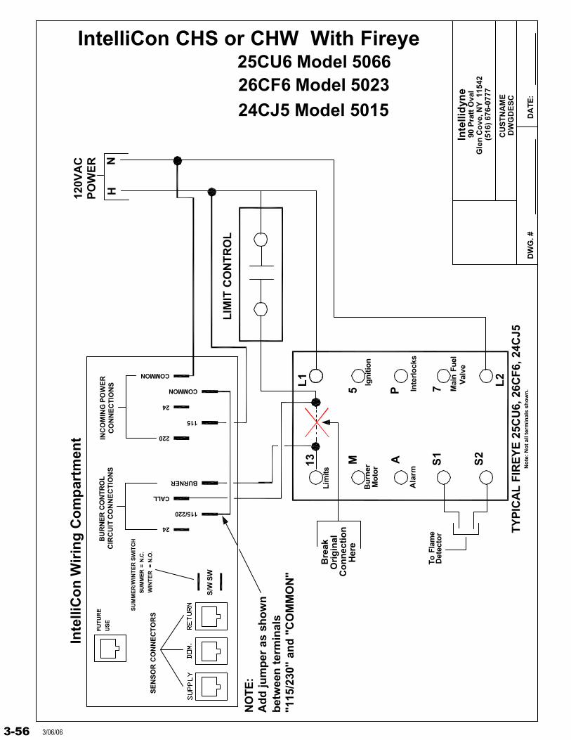
Inte
llid
yne
DW
G. #
DW
GD
ES
C
DA
TE
:
90 P
ratt
Ova
lG
len
Co
ve, N
Y 1
1542
(516
) 67
6-07
77
CU
ST
NA
ME
13 M A S1
S2
L1
5 P
L2
7
HN
120V
AC
PO
WE
R
LIM
IT C
ON
TR
OL
Bu
rner
Mo
tor
Lim
its
Ign
itio
n
Inte
rlo
cks
Mai
n Fu
elV
alve
To F
lam
eD
etec
tor
Bre
ak
Her
e
Ori
gin
alC
on
nec
tio
n
"115
/230
" an
d "
CO
MM
ON
"b
etw
een
ter
min
als
Ad
d ju
mp
er a
s sh
ow
nN
OT
E:
No
te: N
ot a
ll te
rmin
als
sho
wn
.
Ala
rm
TY
PIC
AL
FIR
EY
E 2
5CU
6, 2
6CF
6, 2
4CJ5
IntelliCon CHS or CHW With Fireye25CU6 Model 506626CF6 Model 502324CJ5 Model 5015
SU
MM
ER
= N
.C.
WIN
TE
R =
N.O
.
SU
MM
ER
/WIN
TE
R S
WIT
CH
S/W
SW
Inte
lliC
on
Wir
ing
Co
mp
artm
ent
SE
NS
OR
CO
NN
EC
TO
RS
FU
TU
RE
US
EC
IRC
UIT
CO
NN
EC
TIO
NS
BU
RN
ER
CO
NTR
OL
24
BURNER
115/220
CALL
INC
OM
ING
PO
WE
RC
ON
NE
CT
ION
S
115
220
COMMON
24
COMMON
3-56 3/06/06
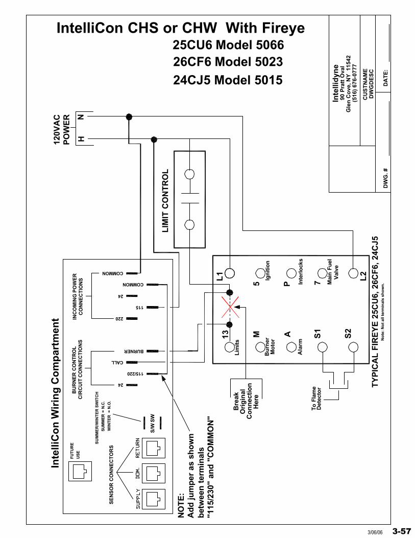
Inte
llid
yne
DW
G. #
DW
GD
ES
C
DA
TE
:
90 P
ratt
Ova
lG
len
Co
ve, N
Y 1
1542
(516
) 67
6-07
77
CU
ST
NA
ME
13 M A S1
S2
L1
5 P
L2
7
HN
120V
AC
PO
WE
R
LIM
IT C
ON
TR
OL
Bu
rner
Mo
tor
Lim
its
Ign
itio
n
Inte
rlo
cks
Mai
n Fu
elV
alve
To F
lam
eD
etec
tor
Bre
ak
Her
e
Ori
gin
alC
on
nec
tio
n
"115
/230
" an
d "
CO
MM
ON
"b
etw
een
ter
min
als
Ad
d ju
mp
er a
s sh
ow
nN
OT
E:
No
te: N
ot a
ll te
rmin
als
sho
wn
.
Ala
rm
TY
PIC
AL
FIR
EY
E 2
5CU
6, 2
6CF
6, 2
4CJ5
IntelliCon CHS or CHW With Fireye25CU6 Model 506626CF6 Model 502324CJ5 Model 5015
SU
MM
ER
= N
.C.
WIN
TE
R =
N.O
.
SU
MM
ER
/WIN
TE
R S
WIT
CH
S/W
SW
Inte
lliC
on
Wir
ing
Co
mp
artm
ent
SE
NS
OR
CO
NN
EC
TO
RS
FU
TU
RE
US
EC
IRC
UIT
CO
NN
EC
TIO
NS
BU
RN
ER
CO
NTR
OL
24
BURNER
115/220
CALL
INC
OM
ING
PO
WE
RC
ON
NE
CT
ION
S
115
220
COMMON
24
COMMON
3-573/06/06

Inte
llid
yne
DW
G. #
DW
GD
ES
C
DA
TE
:
90 P
ratt
Ova
lG
len
Co
ve, N
Y 1
1542
(516
) 67
6-07
77
CU
ST
NA
ME
13 M A S1
S2
L1
5 P
L2
7
HN
120V
AC
PO
WE
R
LIM
IT C
ON
TR
OL
Bu
rner
Mo
tor
Lim
its
Ign
itio
n
Inte
rlo
cks
Mai
n Fu
elV
alve
To F
lam
eD
etec
tor
Bre
ak
Her
e
Ori
gin
alC
on
nec
tio
n
"115
/230
" an
d "
CO
MM
ON
"b
etw
een
ter
min
als
Ad
d ju
mp
er a
s sh
ow
nN
OT
E:
No
te: N
ot a
ll te
rmin
als
sho
wn
.
Ala
rm
TY
PIC
AL
FIR
EY
E 2
5CU
6, 2
6CF
6, 2
4CJ5
IntelliCon CHS or CHW With Fireye25CU6 Model 506626CF6 Model 502324CJ5 Model 5015
SU
MM
ER
= N
.C.
WIN
TE
R =
N.O
.
SU
MM
ER
/WIN
TE
R S
WIT
CH
S/W
SW
Inte
lliC
on
Wir
ing
Co
mp
artm
ent
SE
NS
OR
CO
NN
EC
TO
RS
FU
TU
RE
US
EC
IRC
UIT
CO
NN
EC
TIO
NS
BU
RN
ER
CO
NTR
OL
24
BURNER
115/220
CALL
INC
OM
ING
PO
WE
RC
ON
NE
CT
ION
S
115
220
COMMON
24
COMMON
3-58 3/06/06
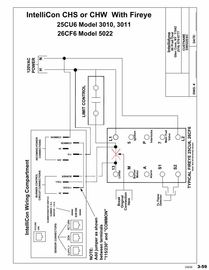
Inte
llid
yne
DW
G. #
DW
GD
ES
C
DA
TE
:
90 P
ratt
Ova
lG
len
Co
ve, N
Y
1154
2(5
16)
676-
0777
CU
STN
AM
E
13 M A S1
S2
L1
5 P
L2
7
HN
120V
AC
PO
WE
R
LIM
IT C
ON
TR
OL
Bu
rner
Mo
tor
Lim
its
Ign
itio
n
Inte
rlo
cks
Mai
n Fu
elV
alve
To F
lam
eD
etec
tor
Bre
ak
Her
e
Ori
gin
alC
on
nec
tio
n
"115
/230
" an
d "
CO
MM
ON
"b
etw
een
ter
min
als
Ad
d ju
mp
er a
s sh
ow
nN
OT
E:
No
te: N
ot a
ll te
rmin
als
sho
wn
.
Ala
rm
TY
PIC
AL
FIR
EY
E 2
5CU
6, 2
6CF
6
26CF6 Model 5022
IntelliCon CHS or CHW With Fireye25CU6 Model 3010, 3011
SU
MM
ER
= N
.C.
WIN
TE
R =
N.O
.
SU
MM
ER
/WIN
TE
R S
WIT
CH
S/W
SW
Inte
lliC
on
Wir
ing
Co
mp
artm
ent
SE
NS
OR
CO
NN
EC
TO
RS
FU
TU
RE
US
EC
IRC
UIT
CO
NN
EC
TIO
NS
BU
RN
ER
CO
NTR
OL
24
BURNER
115/220
CALL
INC
OM
ING
PO
WE
RC
ON
NE
CT
ION
S
115
220
COMMON
24
COMMON
3-593/06/06
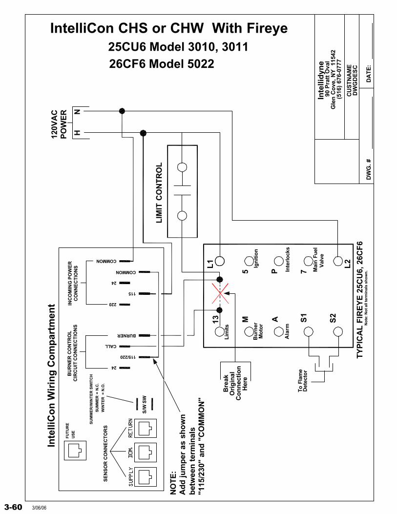
Inte
llid
yne
DW
G. #
DW
GD
ES
C
DA
TE
:
90 P
ratt
Ova
lG
len
Co
ve, N
Y
1154
2(5
16)
676-
0777
CU
STN
AM
E
13 M A S1
S2
L1
5 P
L2
7
HN
120V
AC
PO
WE
R
LIM
IT C
ON
TR
OL
Bu
rner
Mo
tor
Lim
its
Ign
itio
n
Inte
rlo
cks
Mai
n Fu
elV
alve
To F
lam
eD
etec
tor
Bre
ak
Her
e
Ori
gin
alC
on
nec
tio
n
"115
/230
" an
d "
CO
MM
ON
"b
etw
een
ter
min
als
Ad
d ju
mp
er a
s sh
ow
nN
OT
E:
No
te: N
ot a
ll te
rmin
als
sho
wn
.
Ala
rm
TY
PIC
AL
FIR
EY
E 2
5CU
6, 2
6CF
6
26CF6 Model 5022
IntelliCon CHS or CHW With Fireye25CU6 Model 3010, 3011
SU
MM
ER
= N
.C.
WIN
TE
R =
N.O
.
SU
MM
ER
/WIN
TE
R S
WIT
CH
S/W
SW
Inte
lliC
on
Wir
ing
Co
mp
artm
ent
SE
NS
OR
CO
NN
EC
TO
RS
FU
TU
RE
US
EC
IRC
UIT
CO
NN
EC
TIO
NS
BU
RN
ER
CO
NTR
OL
24
BURNER
115/220
CALL
INC
OM
ING
PO
WE
RC
ON
NE
CT
ION
S
115
220
COMMON
24
COMMON
3-60 3/06/06
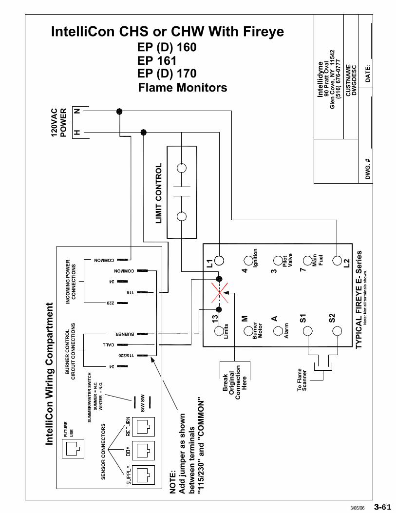
Inte
llid
yne
DW
G. #
DW
GD
ES
C
DA
TE
:
90 P
ratt
Ova
lG
len
Co
ve, N
Y
1154
2(5
16)
676-
0777
CU
STN
AM
E
13 M A S1
S2
L1
4 3
L2
7
HN
120V
AC
PO
WE
R
LIM
IT C
ON
TR
OL
Bu
rner
Mo
tor
Lim
its
Ign
itio
n
Mai
nF
uel
To F
lam
eS
can
ner
Bre
ak
Her
e
Ori
gin
alC
on
nec
tio
n
"115
/230
" an
d "
CO
MM
ON
"b
etw
een
ter
min
als
Ad
d ju
mp
er a
s sh
ow
nN
OT
E:
No
te: N
ot a
ll te
rmin
als
sho
wn
.
Ala
rm
TY
PIC
AL
FIR
EY
E E
- S
erie
s
Val
veP
ilot
EP (D) 170Flame Monitors
EP (D) 160IntelliCon CHS or CHW With Fireye
EP 161
SU
MM
ER
= N
.C.
WIN
TE
R =
N.O
.
SU
MM
ER
/WIN
TE
R S
WIT
CH
S/W
SW
Inte
lliC
on
Wir
ing
Co
mp
artm
ent
SE
NS
OR
CO
NN
EC
TO
RS
FU
TU
RE
US
EC
IRC
UIT
CO
NN
EC
TIO
NS
BU
RN
ER
CO
NTR
OL
24
BURNER
115/220
CALL
INC
OM
ING
PO
WE
RC
ON
NE
CT
ION
S
115
220
COMMON
24
COMMON
3-613/06/06
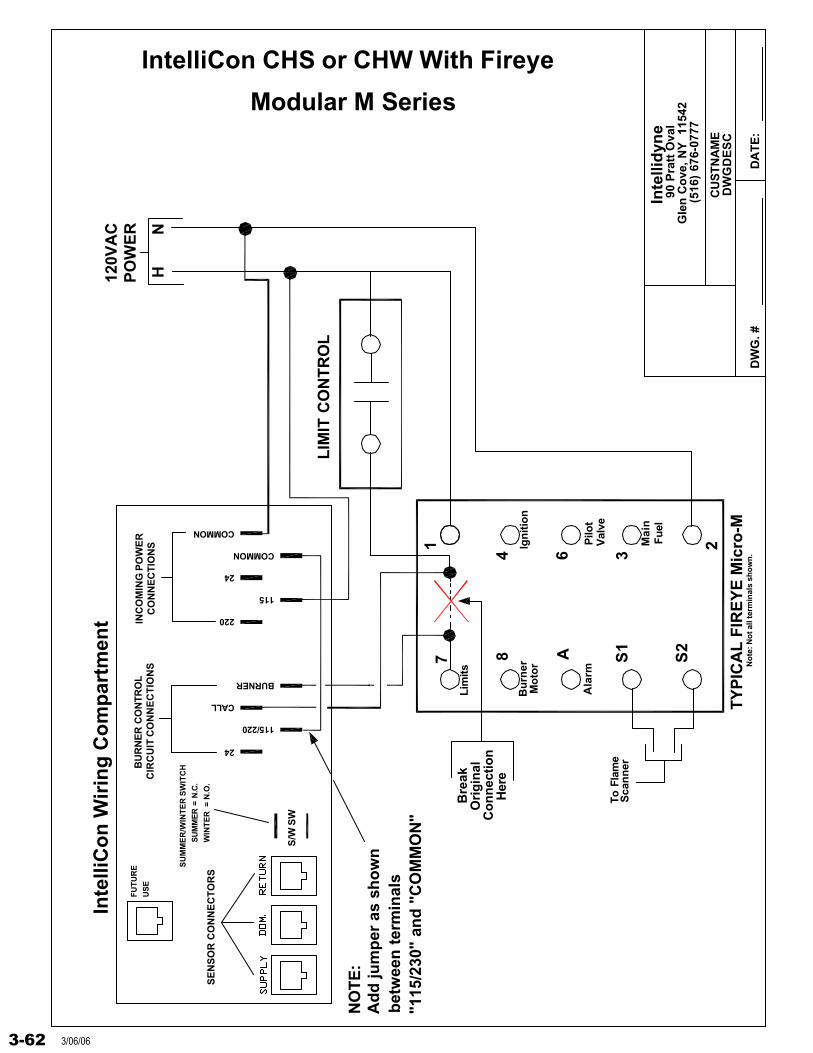
Inte
llid
yne
DW
G. #
DW
GD
ES
C
DA
TE
:
90 P
ratt
Ova
lG
len
Co
ve, N
Y
1154
2(5
16)
676-
0777
CU
STN
AM
E
7 8 A S1
S2
1
4 6
2
3
HN
120V
AC
PO
WE
R
LIM
IT C
ON
TR
OL
Bu
rner
Mo
tor
Lim
its
Ign
itio
n
Pilo
t
Mai
nF
uel
To F
lam
eS
can
ner
Bre
ak
Her
e
Ori
gin
alC
on
nec
tio
n
"115
/230
" an
d "
CO
MM
ON
"b
etw
een
ter
min
als
Ad
d ju
mp
er a
s sh
ow
nN
OT
E:
No
te: N
ot a
ll te
rmin
als
sho
wn
.
Ala
rm
TY
PIC
AL
FIR
EY
E M
icro
-M
Val
ve
IntelliCon CHS or CHW With Fireye
SU
MM
ER
= N
.C.
WIN
TE
R =
N.O
.
SU
MM
ER
/WIN
TE
R S
WIT
CH
S/W
SW
Inte
lliC
on
Wir
ing
Co
mp
artm
ent
SE
NS
OR
CO
NN
EC
TO
RS
FU
TU
RE
US
EC
IRC
UIT
CO
NN
EC
TIO
NS
BU
RN
ER
CO
NTR
OL
24
BURNER
115/220
CALL
INC
OM
ING
PO
WE
RC
ON
NE
CT
ION
S
115
220
COMMON
24
COMMON
Modular M Series
3-62 3/06/06
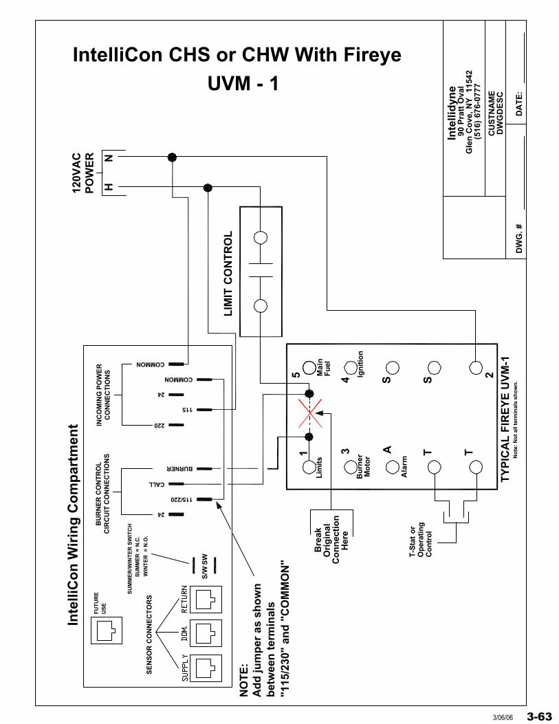
Inte
llid
yne
DW
G. #
DW
GD
ES
C
DA
TE
:
90 P
ratt
Ova
lG
len
Co
ve, N
Y
1154
2(5
16)
676-
0777
CU
STN
AM
E
1 3 A T T
5 4 S 2S
HN
120V
AC
PO
WE
R
LIM
IT C
ON
TR
OL
Bu
rner
Mo
tor
Lim
its
Ign
itio
n
Mai
nF
uel
T-S
tat
or
Op
erat
ing
Bre
ak
Her
e
Ori
gin
alC
on
nec
tio
n
"115
/230
" an
d "
CO
MM
ON
"b
etw
een
ter
min
als
Ad
d ju
mp
er a
s sh
ow
nN
OT
E:
No
te: N
ot a
ll te
rmin
als
sho
wn
.
Ala
rm
TY
PIC
AL
FIR
EY
E U
VM
-1
Co
ntr
ol
IntelliCon CHS or CHW With Fireye
SU
MM
ER
= N
.C.
WIN
TE
R =
N.O
.
SU
MM
ER
/WIN
TE
R S
WIT
CH
S/W
SW
Inte
lliC
on
Wir
ing
Co
mp
artm
ent
SE
NS
OR
CO
NN
EC
TO
RS
FU
TU
RE
US
EC
IRC
UIT
CO
NN
EC
TIO
NS
BU
RN
ER
CO
NTR
OL
24
BURNER
115/220
CALL
INC
OM
ING
PO
WE
RC
ON
NE
CT
ION
S
115
220
COMMON
24
COMMON
UVM - 1
3-633/06/06
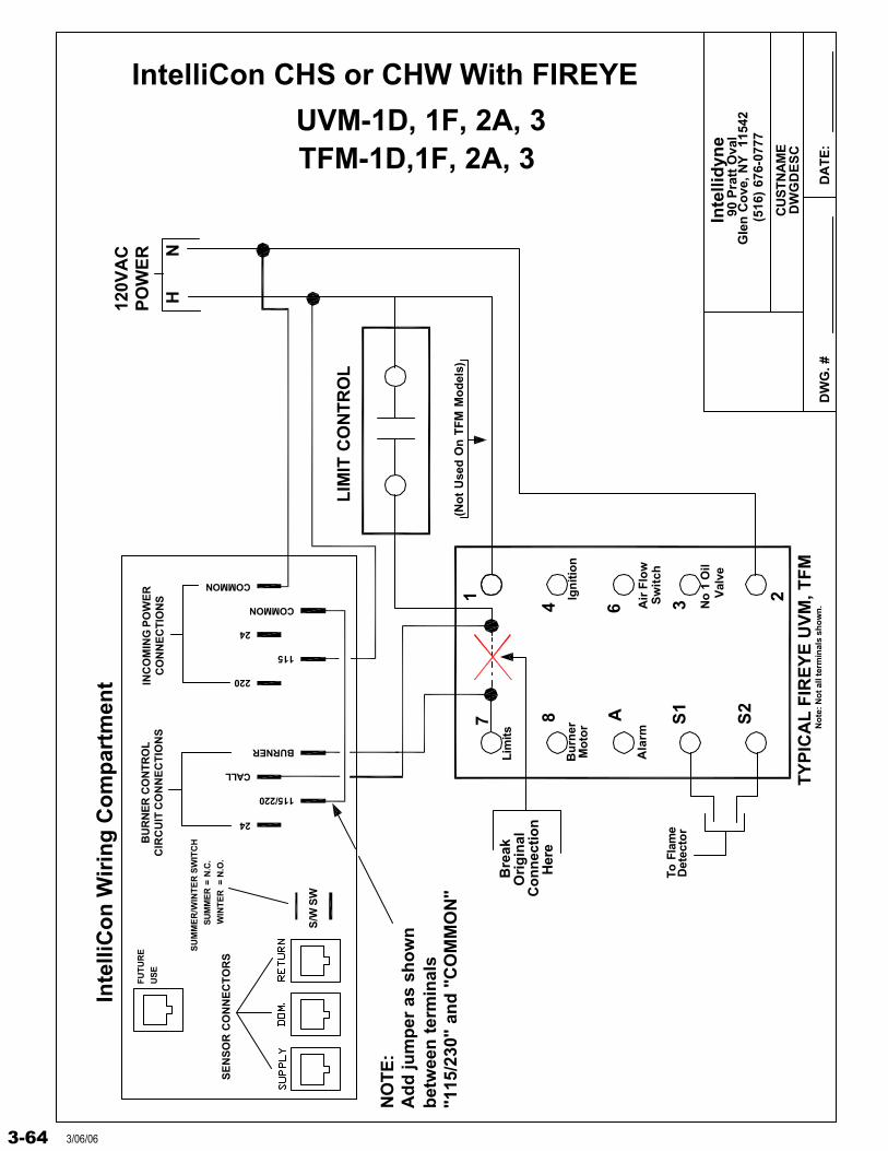
Inte
llid
yne
DW
G. #
DW
GD
ES
C
DA
TE
:
90 P
ratt
Ova
lG
len
Co
ve, N
Y
1154
2(5
16)
676-
0777
CU
STN
AM
E
IntelliCon CHS or CHW With FIREYE
7 8 A S1
S2
1
4 6
23
HN
120V
AC
PO
WE
R
LIM
IT C
ON
TR
OL
Bu
rner
Mo
tor
Lim
its
Ign
itio
n
Air
Flo
w
No
1 O
ilV
alve
To F
lam
eD
etec
tor
Bre
ak
Her
e
Ori
gin
alC
on
nec
tio
n
"115
/230
" an
d "
CO
MM
ON
"b
etw
een
ter
min
als
Ad
d ju
mp
er a
s sh
ow
nN
OT
E:
No
te: N
ot a
ll te
rmin
als
sho
wn
.
TFM-1D,1F, 2A, 3
Ala
rm
TY
PIC
AL
FIR
EY
E U
VM
, TF
M
Sw
itch
(No
t U
sed
On
TF
M M
od
els)
SU
MM
ER
= N
.C.
WIN
TE
R =
N.O
.
SU
MM
ER
/WIN
TE
R S
WIT
CH
S/W
SW
Inte
lliC
on
Wir
ing
Co
mp
artm
ent
SE
NS
OR
CO
NN
EC
TO
RS
FU
TU
RE
US
EC
IRC
UIT
CO
NN
EC
TIO
NS
BU
RN
ER
CO
NTR
OL
24
BURNER
115/220
CALL
INC
OM
ING
PO
WE
RC
ON
NE
CT
ION
S
115
220
COMMON
24
COMMON
UVM-1D, 1F, 2A, 3
3-64 3/06/06
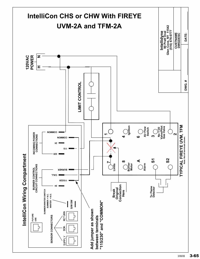
Inte
llid
yne
DW
G. #
DW
GD
ES
C
DA
TE
:
90 P
ratt
Ova
lG
len
Co
ve, N
Y
1154
2(5
16)
676-
0777
CU
STN
AM
E
IntelliCon CHS or CHW With FIREYE
7 8 A S1
S2
1
4 6
23
HN
120V
AC
PO
WE
R
LIM
IT C
ON
TR
OL
Bu
rner
Mo
tor
Lim
its
Ign
itio
n
Air
Flo
w
No
1 O
ilV
alve
/Pilo
t
To F
lam
eD
etec
tor
Bre
ak
Her
e
Ori
gin
alC
on
nec
tio
n
"115
/230
" an
d "
CO
MM
ON
"b
etw
een
ter
min
als
Ad
d ju
mp
er a
s sh
ow
n
No
te: N
ot a
ll te
rmin
als
sho
wn
.
Ala
rm
TY
PIC
AL
FIR
EY
E U
VM
, TF
M
Sw
itch
Gas
Val
ve
SU
MM
ER
= N
.C.
WIN
TE
R =
N.O
.
SU
MM
ER
/WIN
TE
R S
WIT
CH
S/W
SW
Inte
lliC
on
Wir
ing
Co
mp
artm
ent
SE
NS
OR
CO
NN
EC
TO
RS
FU
TU
RE
US
EC
IRC
UIT
CO
NN
EC
TIO
NS
BU
RN
ER
CO
NTR
OL
24
BURNER
115/220
CALL
INC
OM
ING
PO
WE
RC
ON
NE
CT
ION
S
115
220
COMMON
24
COMMON
UVM-2A and TFM-2A
3-653/06/06
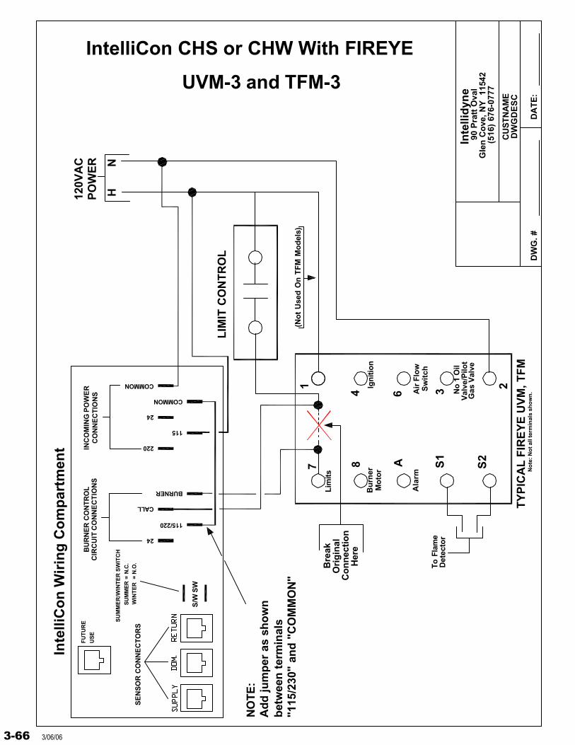
Inte
llid
yne
DW
G. #
DW
GD
ES
C
DA
TE
:
90 P
ratt
Ova
lG
len
Co
ve, N
Y
1154
2(5
16)
676-
0777
CU
STN
AM
E
IntelliCon CHS or CHW With FIREYE
7 8 A S1
S2
1
4 6
23
HN
120V
AC
PO
WE
R
LIM
IT C
ON
TR
OL
Bu
rner
Mo
tor
Lim
its
Ign
itio
n
Air
Flo
w
No
1 O
ilV
alve
/Pilo
t
To F
lam
eD
etec
tor
Bre
ak
Her
e
Ori
gin
alC
on
nec
tio
n
"115
/230
" an
d "
CO
MM
ON
"b
etw
een
ter
min
als
Ad
d ju
mp
er a
s sh
ow
nN
OT
E:
No
te: N
ot a
ll te
rmin
als
sho
wn
.
Ala
rm
TY
PIC
AL
FIR
EY
E U
VM
, TF
M
Sw
itch
Gas
Val
ve
(No
t U
sed
On
TF
M M
od
els)
SU
MM
ER
= N
.C.
WIN
TE
R =
N.O
.
SU
MM
ER
/WIN
TE
R S
WIT
CH
S/W
SW
Inte
lliC
on
Wir
ing
Co
mp
artm
ent
SE
NS
OR
CO
NN
EC
TO
RS
FU
TU
RE
US
EC
IRC
UIT
CO
NN
EC
TIO
NS
BU
RN
ER
CO
NTR
OL
24
BURNER
115/220
CALL
INC
OM
ING
PO
WE
RC
ON
NE
CT
ION
S
115
220
COMMON
24
COMMON
UVM-3 and TFM-3
3-66 3/06/06
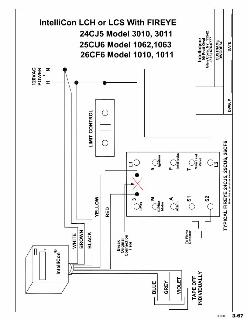
Inte
llid
yne
DW
G. #
DW
GD
ES
C
DA
TE
:
90 P
ratt
Ova
lG
len
Co
ve, N
Y
1154
2(5
16)
676-
0777
CU
STN
AM
E
IntelliCon LCH or LCS With FIREYE
3 M A S1
S2
L1
5 P
L2
7
HN
120V
AC
PO
WE
R
TY
PIC
AL
FIR
EY
E 2
4CJ5
, 25C
U6,
26C
F6
LIM
IT C
ON
TR
OL
Bu
rner
Mo
tor
Lim
its
Ign
itio
n
Inte
rlo
cks
Mai
n Fu
elV
alve
To F
lam
eD
etec
tor
Bre
ak
Her
e
Ori
gin
alC
on
nec
tio
n
Inte
lliC
on
WH
ITE
BR
OW
N
BL
AC
K
RE
D
YE
LL
OW
BL
UE
GR
EY
VIO
LE
T
TA
PE
OF
FIN
DIV
IDU
AL
LY
Ala
rm
25CU6 Model 1062,106326CF6 Model 1010, 1011
No
te: N
ot a
ll te
rmin
als
sho
wn
.
24CJ5 Model 3010, 3011
3-673/06/06
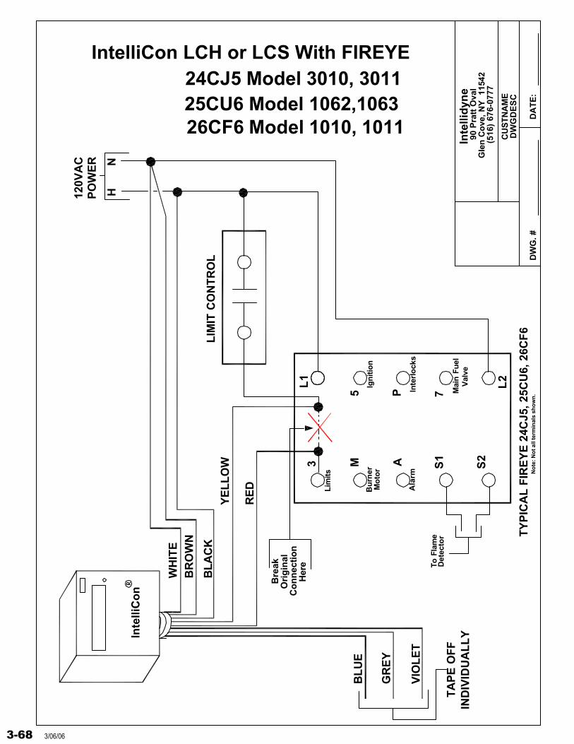
Inte
llid
yne
DW
G. #
DW
GD
ES
C
DA
TE
:
90 P
ratt
Ova
lG
len
Co
ve, N
Y
1154
2(5
16)
676-
0777
CU
STN
AM
E
IntelliCon LCH or LCS With FIREYE
3 M A S1
S2
L1
5 P
L2
7
HN
120V
AC
PO
WE
R
TY
PIC
AL
FIR
EY
E 2
4CJ5
, 25C
U6,
26C
F6
LIM
IT C
ON
TR
OL
Bu
rner
Mo
tor
Lim
its
Ign
itio
n
Inte
rlo
cks
Mai
n Fu
elV
alve
To F
lam
eD
etec
tor
Bre
ak
Her
e
Ori
gin
alC
on
nec
tio
n
Inte
lliC
on
WH
ITE
BR
OW
N
BL
AC
K
RE
D
YE
LL
OW
BL
UE
GR
EY
VIO
LE
T
TA
PE
OF
FIN
DIV
IDU
AL
LY
Ala
rm
25CU6 Model 1062,106326CF6 Model 1010, 1011
No
te: N
ot a
ll te
rmin
als
sho
wn
.
24CJ5 Model 3010, 3011
3-68 3/06/06

Inte
llid
yne
DW
G. #
DW
GD
ES
C
DA
TE
:
90 P
ratt
Ova
lG
len
Co
ve, N
Y
1154
2(5
16)
676-
0777
CU
STN
AM
E
IntelliCon LCH or LCS With FIREYE
3 M A S1
S2
L1
5 P
L2
7
HN
120V
AC
PO
WE
R
TY
PIC
AL
FIR
EY
E 2
4CJ5
, 25C
U6,
26C
F6
LIM
IT C
ON
TR
OL
Bu
rner
Mo
tor
Lim
its
Ign
itio
n
Inte
rlo
cks
Mai
n Fu
elV
alve
To F
lam
eD
etec
tor
Bre
ak
Her
e
Ori
gin
alC
on
nec
tio
n
Inte
lliC
on
WH
ITE
BR
OW
N
BL
AC
K
RE
D
YE
LL
OW
BL
UE
GR
EY
VIO
LE
T
TA
PE
OF
FIN
DIV
IDU
AL
LY
Ala
rm
25CU6 Model 1062,106326CF6 Model 1010, 1011
No
te: N
ot a
ll te
rmin
als
sho
wn
.
24CJ5 Model 3010, 3011
3-693/06/06
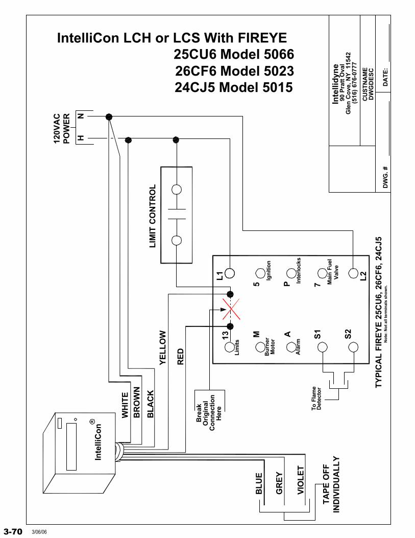
Inte
llid
yne
DW
G. #
DW
GD
ES
C
DA
TE
:
90 P
ratt
Ova
lG
len
Co
ve, N
Y
1154
2(5
16)
676-
0777
CU
STN
AM
E
IntelliCon LCH or LCS With FIREYE
13 M A S1
S2
L1
5 P
L2
7
HN
120V
AC
PO
WE
R
TY
PIC
AL
FIR
EY
E 2
5CU
6, 2
6CF
6, 2
4CJ5LIM
IT C
ON
TR
OL
Bu
rner
Mo
tor
Lim
its
Ign
itio
n
Inte
rlo
cks
Mai
n Fu
elV
alve
To F
lam
eD
etec
tor
Bre
ak
Her
e
Ori
gin
alC
on
nec
tio
n
Inte
lliC
on
WH
ITE
BR
OW
N
BL
AC
K
RE
D
YE
LL
OW
BL
UE
GR
EY
VIO
LE
T
TA
PE
OF
FIN
DIV
IDU
AL
LY
Ala
rm
26CF6 Model 502324CJ5 Model 5015
No
te: N
ot a
ll te
rmin
als
sho
wn
.
25CU6 Model 5066
3-70 3/06/06
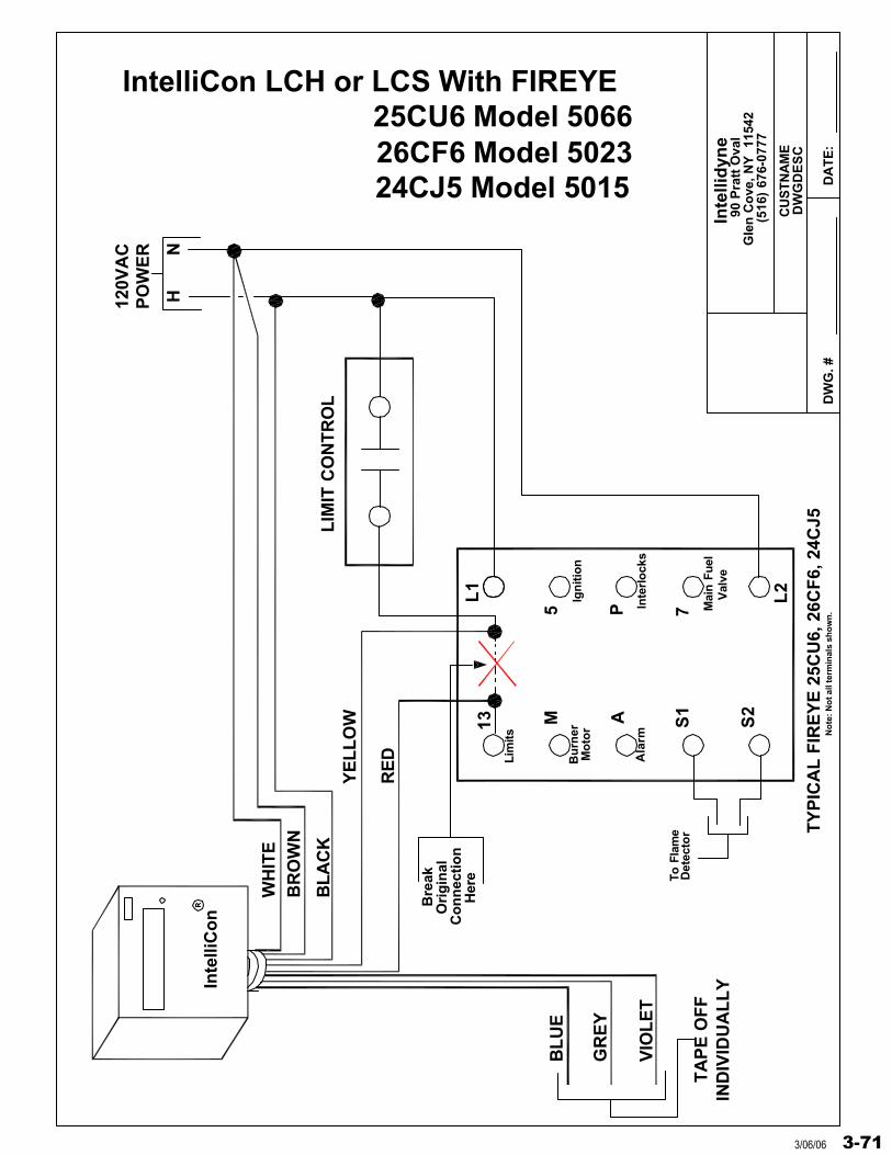
Inte
llid
yne
DW
G. #
DW
GD
ES
C
DA
TE
:
90 P
ratt
Ova
lG
len
Co
ve, N
Y
1154
2(5
16)
676-
0777
CU
STN
AM
E
IntelliCon LCH or LCS With FIREYE
13 M A S1
S2
L1
5 P
L2
7
HN
120V
AC
PO
WE
R
TY
PIC
AL
FIR
EY
E 2
5CU
6, 2
6CF
6, 2
4CJ5LIM
IT C
ON
TR
OL
Bu
rner
Mo
tor
Lim
its
Ign
itio
n
Inte
rlo
cks
Mai
n Fu
elV
alve
To F
lam
eD
etec
tor
Bre
ak
Her
e
Ori
gin
alC
on
nec
tio
n
Inte
lliC
on
WH
ITE
BR
OW
N
BL
AC
K
RE
D
YE
LL
OW
BL
UE
GR
EY
VIO
LE
T
TA
PE
OF
FIN
DIV
IDU
AL
LY
Ala
rm
26CF6 Model 502324CJ5 Model 5015
No
te: N
ot a
ll te
rmin
als
sho
wn
.
25CU6 Model 5066
3-713/06/06

Inte
llid
yne
DW
G. #
DW
GD
ES
C
DA
TE
:
90 P
ratt
Ova
lG
len
Co
ve, N
Y
1154
2(5
16)
676-
0777
CU
STN
AM
E
IntelliCon LCH or LCS With FIREYE
13 M A S1
S2
L1
5 P
L2
7
HN
120V
AC
PO
WE
R
TY
PIC
AL
FIR
EY
E 2
5CU
6, 2
6CF
6, 2
4CJ5LIM
IT C
ON
TR
OL
Bu
rner
Mo
tor
Lim
its
Ign
itio
n
Inte
rlo
cks
Mai
n Fu
elV
alve
To F
lam
eD
etec
tor
Bre
ak
Her
e
Ori
gin
alC
on
nec
tio
n
Inte
lliC
on
WH
ITE
BR
OW
N
BL
AC
K
RE
D
YE
LL
OW
BL
UE
GR
EY
VIO
LE
T
TA
PE
OF
FIN
DIV
IDU
AL
LY
Ala
rm
26CF6 Model 502324CJ5 Model 5015
No
te: N
ot a
ll te
rmin
als
sho
wn
.
25CU6 Model 5066
3-72 3/06/06

Inte
llid
yne
DW
G. #
DW
GD
ES
C
DA
TE
:
90 P
ratt
Ova
lG
len
Co
ve, N
Y
1154
2(5
16)
676-
0777
CU
STN
AM
E
IntelliCon LCH or LCS With FIREYE
13 M A S1
S2
L1
5 P
L2
7
HN
120V
AC
PO
WE
R
TY
PIC
AL
FIR
EY
E 2
5CU
6, 2
6CF
6
LIM
IT C
ON
TR
OL
Bu
rner
Mo
tor
Lim
its
Ign
itio
n
Inte
rlo
cks
Mai
n Fu
elV
alve
To F
lam
eD
etec
tor
Bre
ak
Her
e
Ori
gin
alC
on
nec
tio
n
Inte
lliC
on
WH
ITE
BR
OW
N
BL
AC
K
RE
D
YE
LL
OW
BL
UE
GR
EY
VIO
LE
T
TA
PE
OF
FIN
DIV
IDU
AL
LY
Ala
rm
26CF6 Model 5022
No
te: N
ot a
ll te
rmin
als
sho
wn
.
25CU6 Model 5065
3-733/06/06
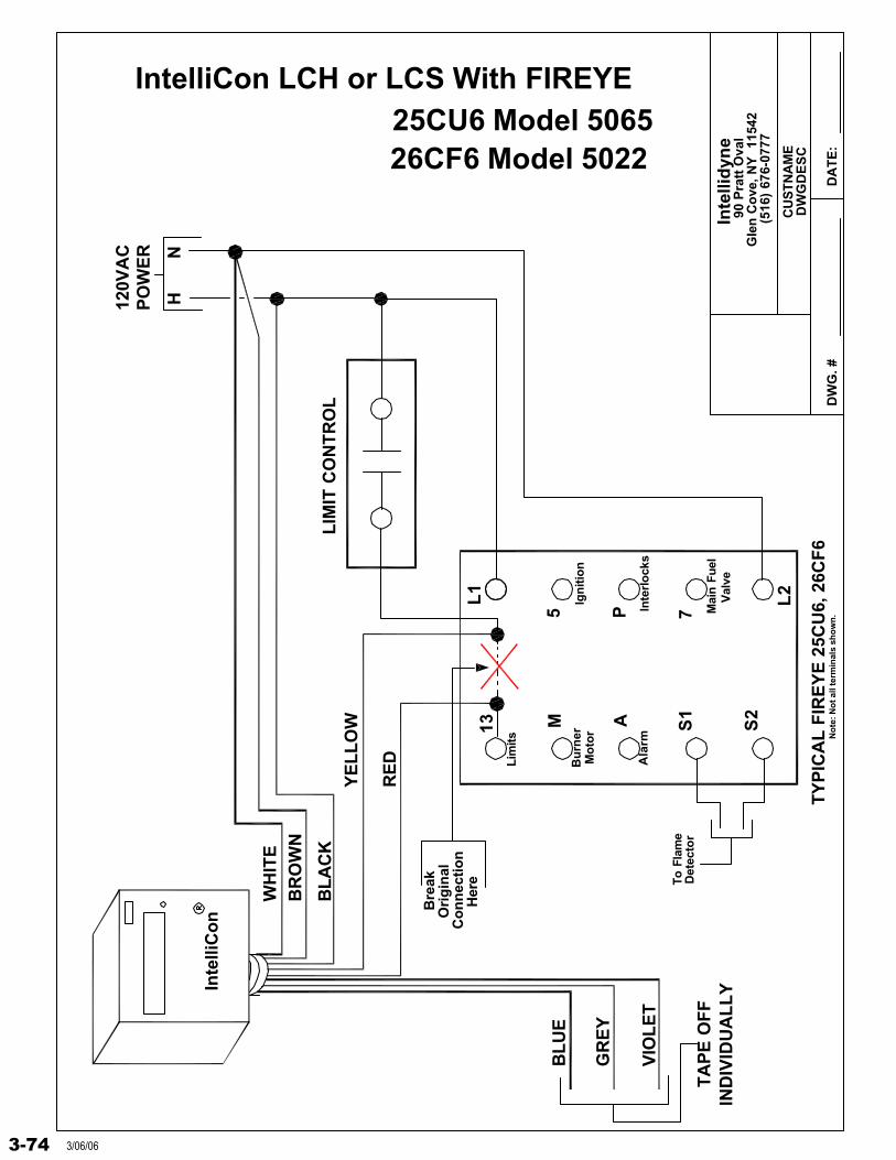
Inte
llid
yne
DW
G. #
DW
GD
ES
C
DA
TE
:
90 P
ratt
Ova
lG
len
Co
ve, N
Y
1154
2(5
16)
676-
0777
CU
STN
AM
E
IntelliCon LCH or LCS With FIREYE
13 M A S1
S2
L1
5 P
L2
7
HN
120V
AC
PO
WE
R
TY
PIC
AL
FIR
EY
E 2
5CU
6, 2
6CF
6
LIM
IT C
ON
TR
OL
Bu
rner
Mo
tor
Lim
its
Ign
itio
n
Inte
rlo
cks
Mai
n Fu
elV
alve
To F
lam
eD
etec
tor
Bre
ak
Her
e
Ori
gin
alC
on
nec
tio
n
Inte
lliC
on
WH
ITE
BR
OW
N
BL
AC
K
RE
D
YE
LL
OW
BL
UE
GR
EY
VIO
LE
T
TA
PE
OF
FIN
DIV
IDU
AL
LY
Ala
rm
26CF6 Model 5022
No
te: N
ot a
ll te
rmin
als
sho
wn
.
25CU6 Model 5065
3-74 3/06/06
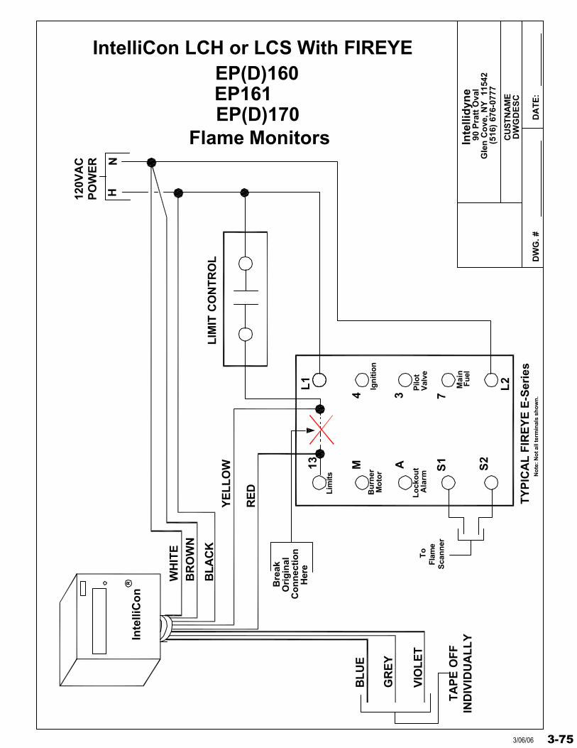
Inte
llid
yne
DW
G. #
DW
GD
ES
C
DA
TE
:
90 P
ratt
Ova
lG
len
Co
ve, N
Y
1154
2(5
16)
676-
0777
CU
STN
AM
E
IntelliCon LCH or LCS With FIREYE
13 M A S1
S2
L1
4 3
L2
7
HN
120V
AC
PO
WE
R
TY
PIC
AL
FIR
EY
E E
-Ser
ies
LIM
IT C
ON
TR
OL
Bu
rner
Mo
tor
Lim
its
Ign
itio
n
Mai
n
To
Flam
e
Bre
ak
Her
e
Ori
gin
alC
on
nec
tio
n
Inte
lliC
on
WH
ITE
BR
OW
N
BL
AC
K
RE
D
YE
LL
OW
BL
UE
GR
EY
VIO
LE
T
TA
PE
OF
FIN
DIV
IDU
AL
LY
Ala
rm No
te: N
ot a
ll te
rmin
als
sho
wn
.
Fu
el
Sca
nn
er
Pilo
tV
alve
EP161EP(D)170
Flame Monitors
Lo
cko
ut
EP(D)160
3-753/06/06
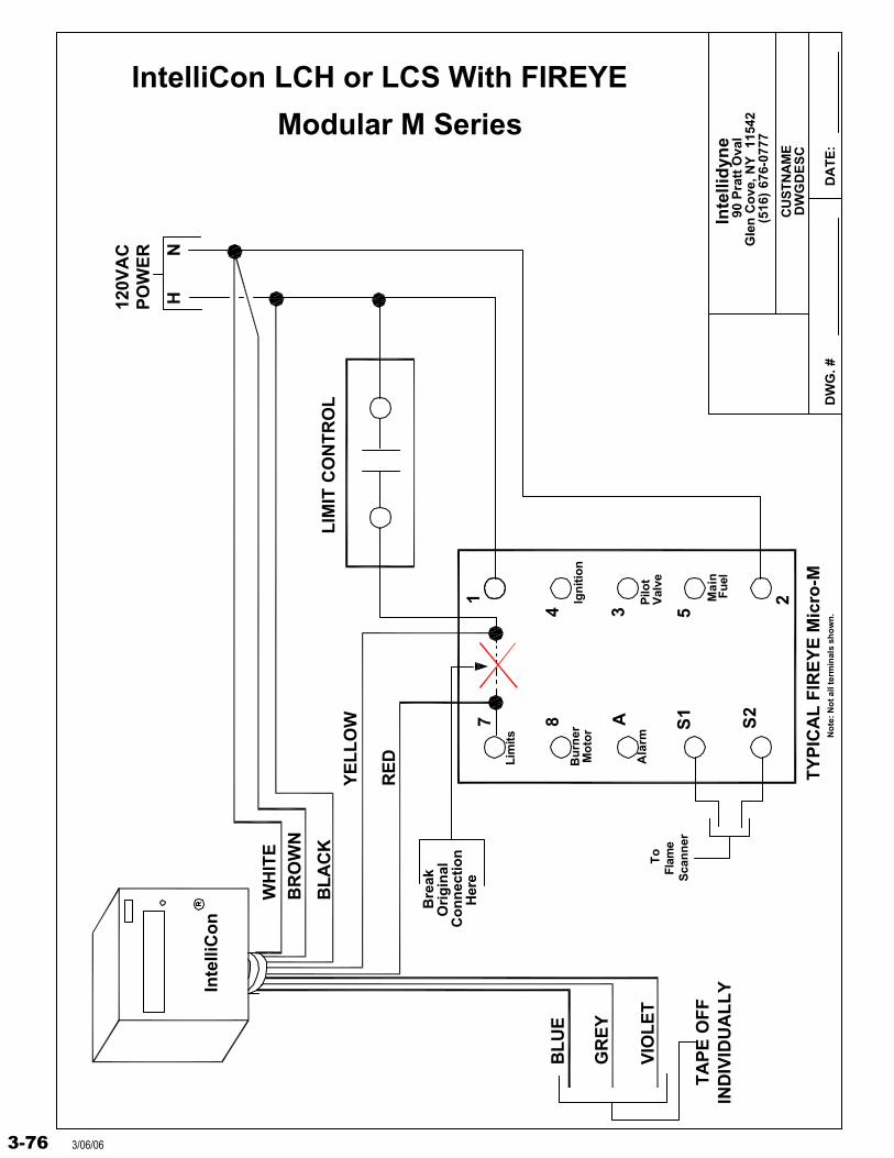
Inte
llid
yne
DW
G. #
DW
GD
ES
C
DA
TE
:
90 P
ratt
Ova
lG
len
Co
ve, N
Y
1154
2(5
16)
676-
0777
CU
STN
AM
E
IntelliCon LCH or LCS With FIREYE
7 8 A S1
S2
1
4 3
2
5
HN
120V
AC
PO
WE
R
TY
PIC
AL
FIR
EY
E M
icro
-M
LIM
IT C
ON
TR
OL
Bu
rner
Mo
tor
Lim
its
Ign
itio
n
Mai
n
To
Flam
e
Bre
ak
Her
e
Ori
gin
alC
on
nec
tio
n
Inte
lliC
on
WH
ITE
BR
OW
N
BL
AC
K
RE
D
YE
LL
OW
BL
UE
GR
EY
VIO
LE
T
TA
PE
OF
FIN
DIV
IDU
AL
LY
Ala
rm No
te: N
ot a
ll te
rmin
als
sho
wn
.
Fu
el
Sca
nn
er
Pilo
tV
alve
Modular M Series
3-76 3/06/06
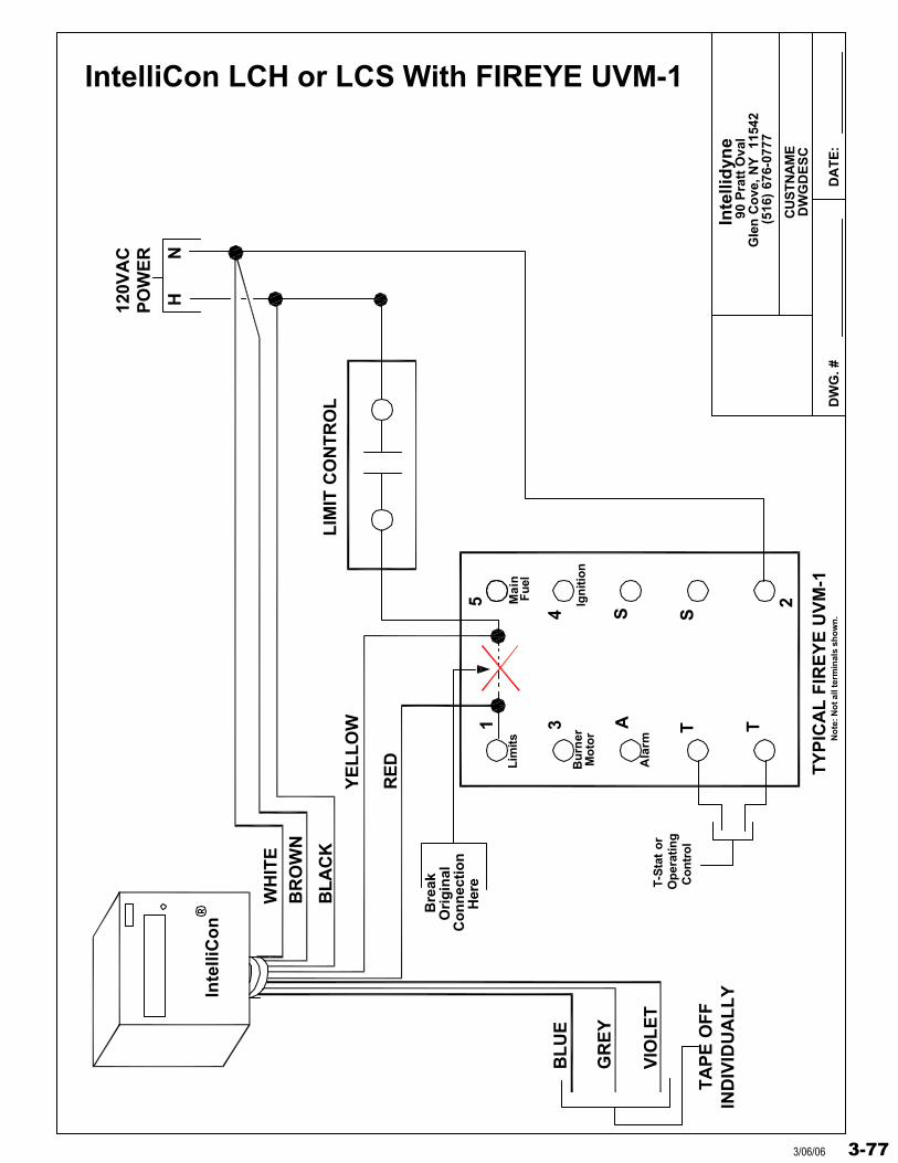
Inte
llid
yne
DW
G. #
DW
GD
ES
C
DA
TE
:
90 P
ratt
Ova
lG
len
Co
ve, N
Y
1154
2(5
16)
676-
0777
CU
STN
AM
E
IntelliCon LCH or LCS With FIREYE UVM-1
1 3 A T T
5
4 S
2
S
HN
120V
AC
PO
WE
R
TY
PIC
AL
FIR
EY
E U
VM
-1
LIM
IT C
ON
TR
OL
Bu
rner
Mo
tor
Lim
its
Ign
itio
n
Mai
n
T-S
tat
or
Op
erat
ing
Bre
ak
Her
e
Ori
gin
alC
on
nec
tio
n
Inte
lliC
on
WH
ITE
BR
OW
N
BL
AC
K
RE
D
YE
LL
OW
BL
UE
GR
EY
VIO
LE
T
TA
PE
OF
FIN
DIV
IDU
AL
LY
Ala
rm No
te: N
ot a
ll te
rmin
als
sho
wn
.
Fu
el
Co
ntr
ol
3-773/06/06
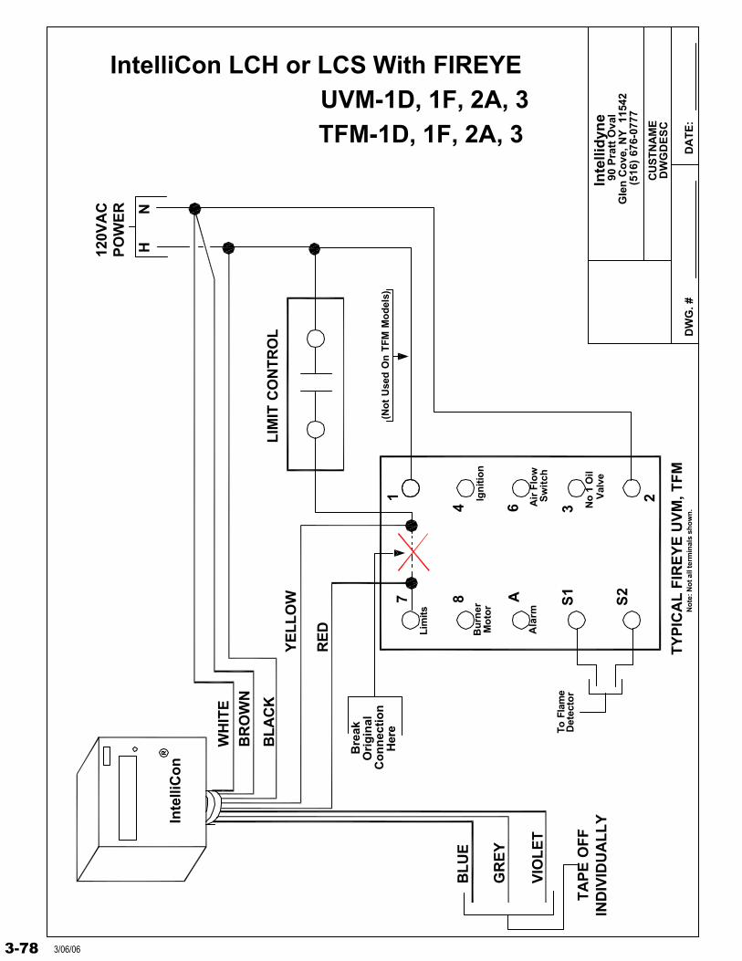
Inte
llid
yne
DW
G. #
DW
GD
ES
C
DA
TE
:
90 P
ratt
Ova
lG
len
Co
ve, N
Y
1154
2(5
16)
676-
0777
CU
STN
AM
E
IntelliCon LCH or LCS With FIREYE
7 8 A S1
S2
1
4 6
2
3
HN
120V
AC
PO
WE
R
TY
PIC
AL
FIR
EY
E U
VM
, TF
M
LIM
IT C
ON
TR
OL
Bu
rner
Mo
tor
Lim
its
Ign
itio
n
Air
Flo
w
No
1 O
ilV
alve
To F
lam
eD
etec
tor
Bre
ak
Her
e
Ori
gin
alC
on
nec
tio
n
Inte
lliC
on
WH
ITE
BR
OW
N
BL
AC
K
RE
D
YE
LL
OW
BL
UE
GR
EY
VIO
LE
T
TA
PE
OF
FIN
DIV
IDU
AL
LY
Ala
rm
TFM-1D, 1F, 2A, 3
No
te: N
ot a
ll te
rmin
als
sho
wn
.
Sw
itch
(No
t U
sed
On
TF
M M
od
els)
UVM-1D, 1F, 2A, 3
3-78 3/06/06
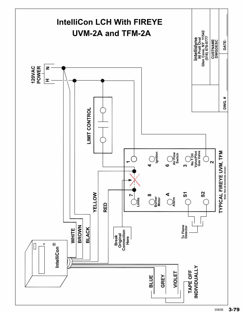
Inte
llid
yne
DW
G. #
DW
GD
ES
C
DA
TE
:
90 P
ratt
Ova
lG
len
Co
ve, N
Y
1154
2(5
16)
676-
0777
CU
STN
AM
E
IntelliCon LCH With FIREYE
7 8 A S1
S2
1
4 6
2
3
HN
120V
AC
PO
WE
R
TY
PIC
AL
FIR
EY
E U
VM
, TF
M
LIM
IT C
ON
TR
OL
Bu
rner
Mo
tor
Lim
its
Ign
itio
n
Air
Flo
w
No
1 O
ilV
alve
/Pilo
t
To F
lam
eD
etec
tor
Bre
ak
Her
e
Ori
gin
alC
on
nec
tio
n
Inte
lliC
on
WH
ITE
BR
OW
N
BL
AC
K
RE
D
YE
LL
OW
BL
UE
GR
EY
VIO
LE
T
TA
PE
OF
FIN
DIV
IDU
AL
LY
Ala
rm No
te: N
ot a
ll te
rmin
als
sho
wn
.
Sw
itch
Gas
Val
ve
UVM-2A and TFM-2A
3-793/06/06
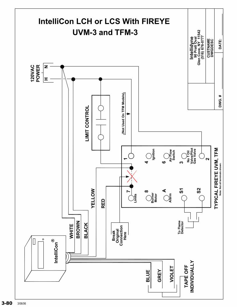
Inte
llid
yne
DW
G. #
DW
GD
ES
C
DA
TE
:
90 P
ratt
Ova
lG
len
Co
ve, N
Y
1154
2(5
16)
676-
0777
CU
STN
AM
E
IntelliCon LCH or LCS With FIREYE
7 8 A S1
S2
1
4 6
2
3
HN
120V
AC
PO
WE
R
TY
PIC
AL
FIR
EY
E U
VM
, TF
M
LIM
IT C
ON
TR
OL
Bu
rner
Mo
tor
Lim
its
Ign
itio
n
Air
Flo
w
No
1 O
ilV
alve
/Pilo
t
To F
lam
eD
etec
tor
Bre
ak
Her
e
Ori
gin
alC
on
nec
tio
n
Inte
lliC
on
WH
ITE
BR
OW
N
BL
AC
K
RE
D
YE
LL
OW
BL
UE
GR
EY
VIO
LE
T
TA
PE
OF
FIN
DIV
IDU
AL
LY
Ala
rm No
te: N
ot a
ll te
rmin
als
sho
wn
.
Sw
itch
(No
t U
sed
On
TF
M M
od
els)
Gas
Val
ve
UVM-3 and TFM-3
3-80 3/06/06
Honeywell Flame Safeguard Controls
General Instructions
The IntelliCon® Heating Economizers are connected in series in the burner control circuit AFTER the operating safety’s and limit controls and BEFORE the burner Flame Safeguard Primary Control.
***ATTENTION MUST BE GIVEN WHEN A DRAFT INDUCER IS USED ON THE BOILER***
*** When a draft inducer is being used, the operating limit control, onclosure, will activate a relay, contactor or starter to enable the draft inducer. An air proving switch will close indicating that the draft inducer is running and a negative air flow has been established through the boiler. Once the negative airflow has been established the Flame Safeguard is enabled and starts the burner sequence.
Improperly connected into the operating limit circuit, the draft inducer will run drawing ambient (or cooler) air through the boiler while the IntelliCon® Heating Economizer is in the “ECONOMY” mode.
Each installation should be checked for the proper connection point of the IntelliCon® Heating Economizer.
The following wiring diagrams show the connection points of theIntelliCon® Heating Economizer at the Honeywell Flame Safeguard ONLY. If a draft inducer is used as explained above, determine the connection pointfrom the operating limit control BEFORE the Flame Safeguard Control.
3-813/06/06
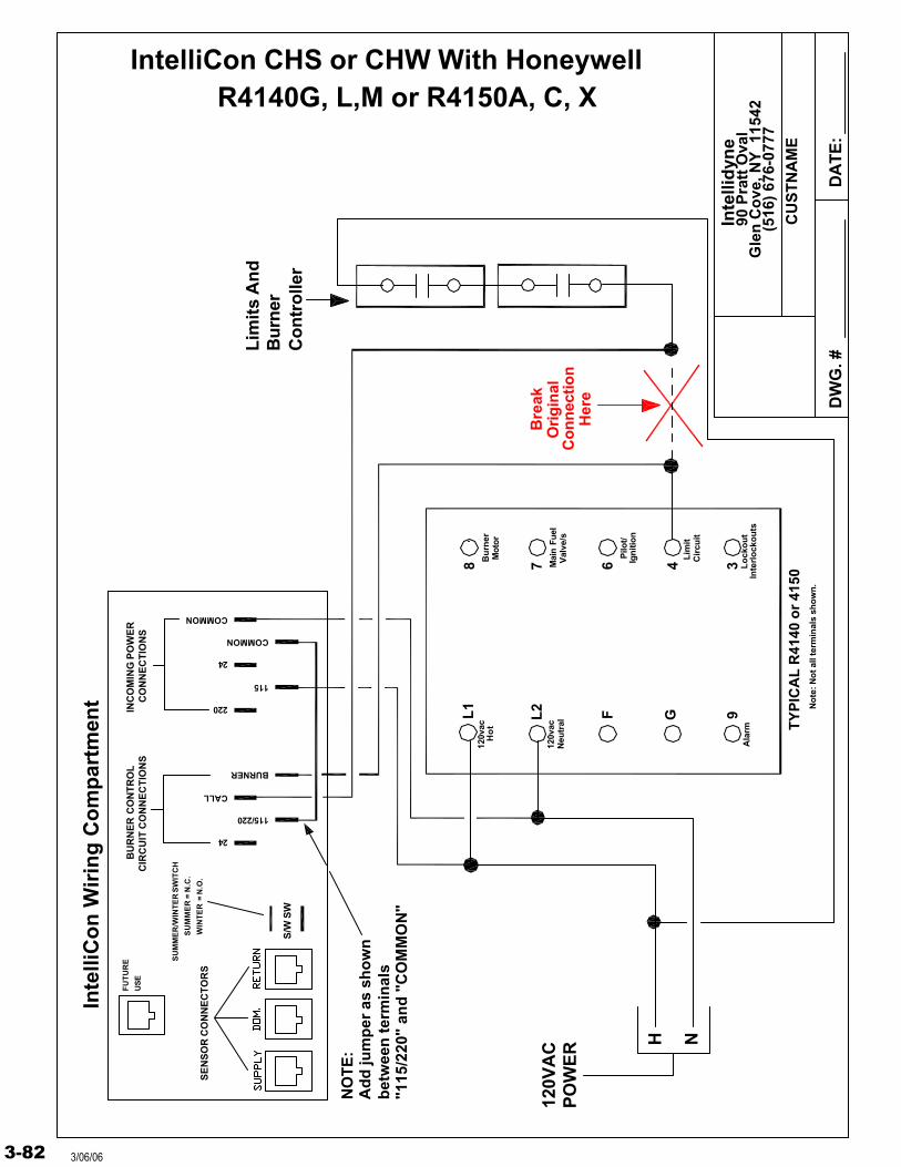
Inte
llid
yne
DW
G. #
D
AT
E:
90 P
ratt
Ova
lG
len
Co
ve, N
Y 1
1542
(516
) 67
6-07
77
CU
ST
NA
ME
Co
ntr
olle
r
TY
PIC
AL
R41
40 o
r 41
50
Ori
gin
al
Lo
cko
ut
Co
nn
ecti
on
Her
e
Inte
rlo
cko
uts
Bre
ak
4 Cir
cuit
Lim
it
3Ign
itio
nP
ilot/
6Bu
rner
Mot
or
Val
ve/s
Mai
n Fu
el
78
Ala
rm
PO
WE
R12
0VA
C
G 9F
Neu
tral
120v
ac
120v
acH
ot
L2L1
Bu
rner
Lim
its
An
d
R4140G, L,M or R4150A, C, XIntelliCon CHS or CHW With Honeywell
H N
No
te: N
ot a
ll te
rmin
als
sho
wn
.
SU
MM
ER
= N
.C.
WIN
TE
R =
N.O
.
SU
MM
ER
/WIN
TE
R S
WIT
CH
S/W
SW
Inte
lliC
on
Wir
ing
Co
mp
artm
ent
SE
NS
OR
CO
NN
EC
TO
RS
FU
TU
RE
US
EC
IRC
UIT
CO
NN
EC
TIO
NS
BU
RN
ER
CO
NT
RO
L
24
BURNER
115/220
CALL
INC
OM
ING
PO
WE
RC
ON
NE
CT
ION
S
115
220
COMMON
24
COMMON
"115
/220
" an
d "
CO
MM
ON
"b
etw
een
ter
min
als
NO
TE
:A
dd
jum
per
as
sho
wn
3-82 3/06/06
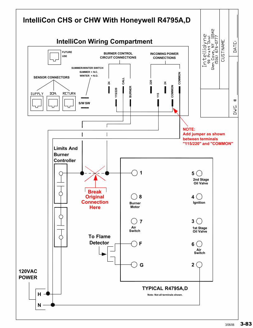
Controller
TYPICAL R4795A,D
OriginalConnection
Here
Break
6
2
3
4
5
POWER120VAC
F
G
7
8
1
BurnerLimits And
H
N
IntelliCon CHS or CHW With Honeywell R4795A,D
Oil Valve2nd Stage
Ignition
Oil Valve1st Stage
SwitchAir
BurnerMotor
SwitchAir
To FlameDetector
Note: Not all terminals shown.
CIRCUIT CONNECTIONSBURNER CONTROL
IntelliCon Wiring Compartment
115/
220
SENSOR CONNECTORS
S/W SW
24
SUMMER/WINTER SWITCH
WINTER = N.O.
SUMMER = N.C.
FUTURE
USE
CO
MM
ON
CA
LL
BU
RN
ER
CO
MM
ON
115
220
24
CONNECTIONSINCOMING POWER
Add jumper as shown
"115/220" and "COMMON"between terminals
NOTE:
3-833/06/06
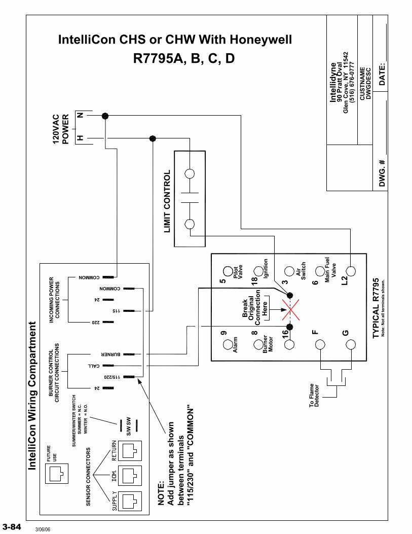
Inte
llid
yne
DW
G. #
DW
GD
ES
C
DA
TE
:
90 P
ratt
Ova
lG
len
Co
ve, N
Y
1154
2(5
16)
676-
0777
CU
STN
AM
E
IntelliCon CHS or CHW With Honeywell
9 8 16 F G
5 18 3 L26
HN
120V
AC
PO
WE
R
TY
PIC
AL
R77
95
LIM
IT C
ON
TR
OL
Bu
rner
Mo
tor
Pilo
t V
alve
Ala
rm
Ign
itio
n
Air
Sw
itch
Mai
n Fu
elV
alve
To F
lam
eD
etec
tor
Bre
ak
Her
e
Ori
gin
alC
on
nec
tio
n
"115
/230
" an
d "
CO
MM
ON
"b
etw
een
ter
min
als
Ad
d ju
mp
er a
s sh
ow
nN
OT
E:
No
te: N
ot a
ll te
rmin
als
sho
wn
.
R7795A, B, C, DS
UM
ME
R =
N.C
.
WIN
TE
R =
N.O
.
SU
MM
ER
/WIN
TE
R S
WIT
CH
S/W
SW
Inte
lliC
on
Wir
ing
Co
mp
artm
ent
SE
NS
OR
CO
NN
EC
TO
RS
FU
TU
RE
US
EC
IRC
UIT
CO
NN
EC
TIO
NS
BU
RN
ER
CO
NTR
OL
24
BURNER
115/220
CALL
INC
OM
ING
PO
WE
RC
ON
NE
CT
ION
S
115
220
COMMON
24
COMMON
3-84 3/06/06
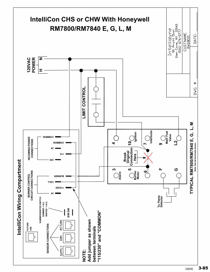
IntelliCon CHS or CHW With Honeywell
3 5 6 F G
4 10 7 L29
HN
120V
AC
PO
WE
R
TY
PIC
AL
RM
7800
/RM
7840
E, G
, L
, M
LIM
IT C
ON
TR
OL
Bu
rner
Mo
tor
Ala
rm
Ign
itio
n
Inte
rlo
cks
Mai
n Fu
elV
alve
To F
lam
eD
etec
tor
Bre
ak
Her
e
Ori
gin
alC
on
nec
tio
n
"115
/230
" an
d "
CO
MM
ON
"b
etw
een
ter
min
als
Ad
d ju
mp
er a
s sh
ow
nN
OT
E:
No
te: N
ot a
ll te
rmin
als
sho
wn
.
RM7800/RM7840 E, G, L, M
SU
MM
ER
= N
.C.
WIN
TE
R =
N.O
.
SU
MM
ER
/WIN
TE
R S
WIT
CH
S/W
SW
Inte
lliC
on
Wir
ing
Co
mp
artm
ent
SE
NS
OR
CO
NN
EC
TO
RS
FU
TU
RE
US
EC
IRC
UIT
CO
NN
EC
TIO
NS
BU
RN
ER
CO
NTR
OL
24
BURNER
115/220
CALL
INC
OM
ING
PO
WE
RC
ON
NE
CT
ION
S
115
220
COMMON
24
COMMON
3-853/06/06
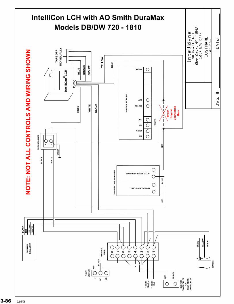
Inte
lliC
on
LC
H
BL
AC
K
YE
LL
OW
RE
D
BL
UE
VIO
LE
T
GR
EY
TA
PE
OF
F
IND
IVID
UA
LL
Y
WH
ITE
BR
OW
N
120v
acH
ot
120v
acN
eutr
al
IntelliCon LCH with AO Smith DuraMaxModels DB/DW 720 - 1810
Bre
ak
Co
nn
ecti
on
Her
e
Ori
gin
al
8 7 6 5 4 3 2 1
MANUAL HIGH LIMIT
AUTO RESET HIGH LIMIT
FLO
W
TE
RM
INA
L
CO
MB
INA
TIO
N H
IGH
LIM
IT
SW
ITC
H
STR
IP
MV
MV/PV
PV
GND
24V (G)
24V
SPARK
TRA
NS
FOR
ME
R
BL
AC
K
WH
ITE
R C
GR
EE
N
RED
BL
UE
WH
ITE
RED
C
NO NC
RED
BL
AC
K
CO
NTR
OLL
ER
OR
TA
NK
TE
MP
.C
ON
TRO
LLE
R
SY
STE
M
SW
ITC
H
RED
BL
AC
K
TH
ER
MA
LB
ALA
NC
ER
BL
AC
K
RED
YE
LLO
WW
HIT
E
3 2 1
WH
ITE
YE
LLO
W
BL
AC
K
IGN
ITIO
N M
OD
UL
E
NO
TE
: NO
T A
LL
CO
NT
RO
LS
AN
D W
IRIN
G S
HO
WN
3-86 3/06/06
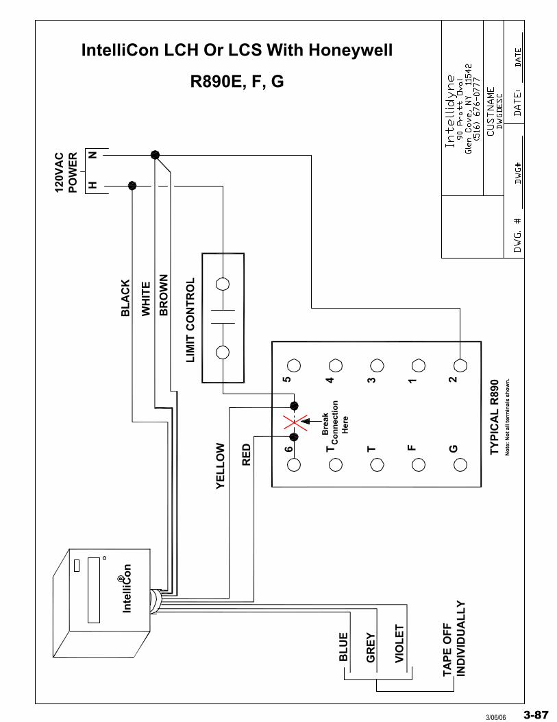
Inte
lliC
on
IND
IVID
UA
LL
YT
AP
E O
FF
GR
EY
VIO
LE
T
BL
UE
LIM
IT C
ON
TR
OL
G TY
PIC
AL
R89
0
FTT6
1 2345
YE
LL
OW
RE
D
BL
AC
K
WH
ITE
BR
OW
N
120V
AC
PO
WE
R
IntelliCon LCH Or LCS With Honeywell
No
te: N
ot a
ll te
rmin
als
sho
wn
.
Bre
akC
on
nec
tion
Her
e
NH
R890E, F, G
3-873/06/06
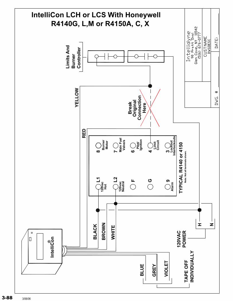
Inte
lliC
on
L1
L2 F G 9
8 7 6 34
H N
120V
AC
PO
WE
RT
YP
ICA
L R
4140
or
4150
BL
AC
K
YE
LL
OW
RE
D
BL
UE
VIO
LE
T
GR
EY
TA
PE
OF
FIN
DIV
IDU
AL
LY
Lim
its
An
dB
urn
erC
on
tro
ller
WH
ITE
BR
OW
N
Ala
rmL
ock
ou
tIn
terl
ock
ou
ts
Pilo
t/Ig
nit
ion
Lim
itC
ircu
it
Mai
n Fu
elV
alve
/s
Bu
rner
Mo
tor
120v
acH
ot
120v
acN
eutr
al
IntelliCon LCH or LCS With Honeywell R4140G, L,M or R4150A, C, X
Bre
ak
Co
nn
ecti
on
Her
e
Ori
gin
al
No
te: N
ot a
ll te
rmin
als
sho
wn
.
3-88 3/06/06
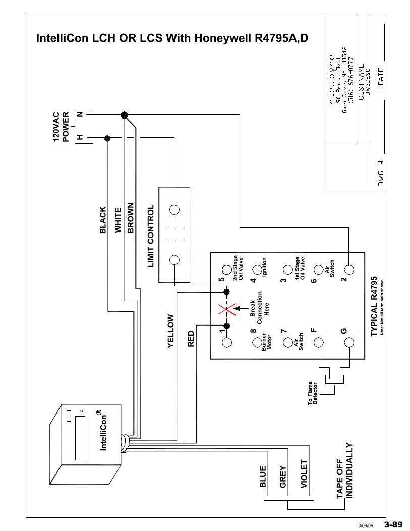
IntelliCon LCH OR LCS With Honeywell R4795A,D
Inte
lliC
on
1 8 7 F G
5 4 3 26
HN
120V
AC
PO
WE
R
TY
PIC
AL
R47
95
LIM
IT C
ON
TR
OL
BL
AC
K
WH
ITE
BR
OW
N
YE
LL
OW
RE
D
BL
UE
VIO
LE
T
GR
EY
TA
PE
OF
FIN
DIV
IDU
AL
LY
Bu
rner
Mo
tor
2nd
Sta
geO
il V
alve
1st S
tage
Oil
Val
ve
Ign
itio
n
Air
Sw
itch
Air
Sw
itch
To F
lam
eD
etec
tor
No
te: N
ot a
ll te
rmin
als
sho
wn
.
Her
eC
on
nec
tion
Bre
ak
3-893/06/06
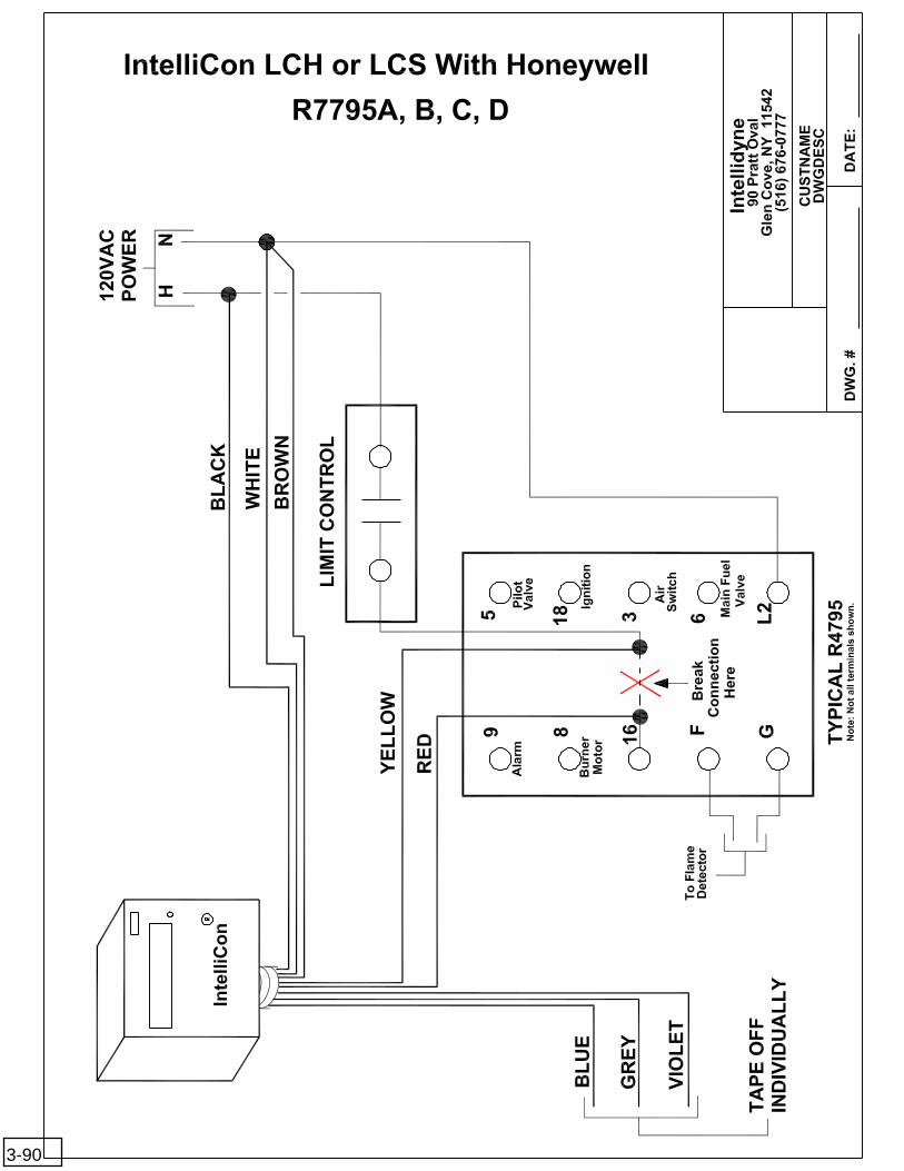
3-90
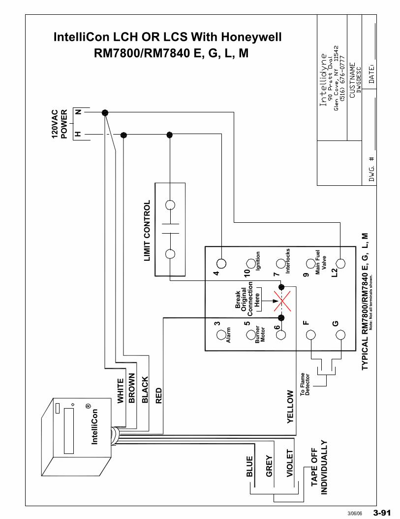
IntelliCon LCH OR LCS With Honeywell
3 5 6 F G
4 10 7 L29
HN
120V
AC
PO
WE
R
TY
PIC
AL
RM
7800
/RM
7840
E, G
, L
, M
LIM
IT C
ON
TR
OL
Bu
rner
Mo
tor
Ala
rm
Ign
itio
n
Inte
rlo
cks
Mai
n Fu
elV
alve
To F
lam
eD
etec
tor
Bre
ak
Her
e
Ori
gin
alC
on
nec
tio
n
Inte
lliC
on
WH
ITE
BR
OW
N
BL
AC
K
RE
D
YE
LL
OW
BL
UE
GR
EY
VIO
LE
T
TA
PE
OF
FIN
DIV
IDU
AL
LY
No
te: N
ot a
ll te
rmin
als
sho
wn
.
RM7800/RM7840 E, G, L, M
3-913/06/06
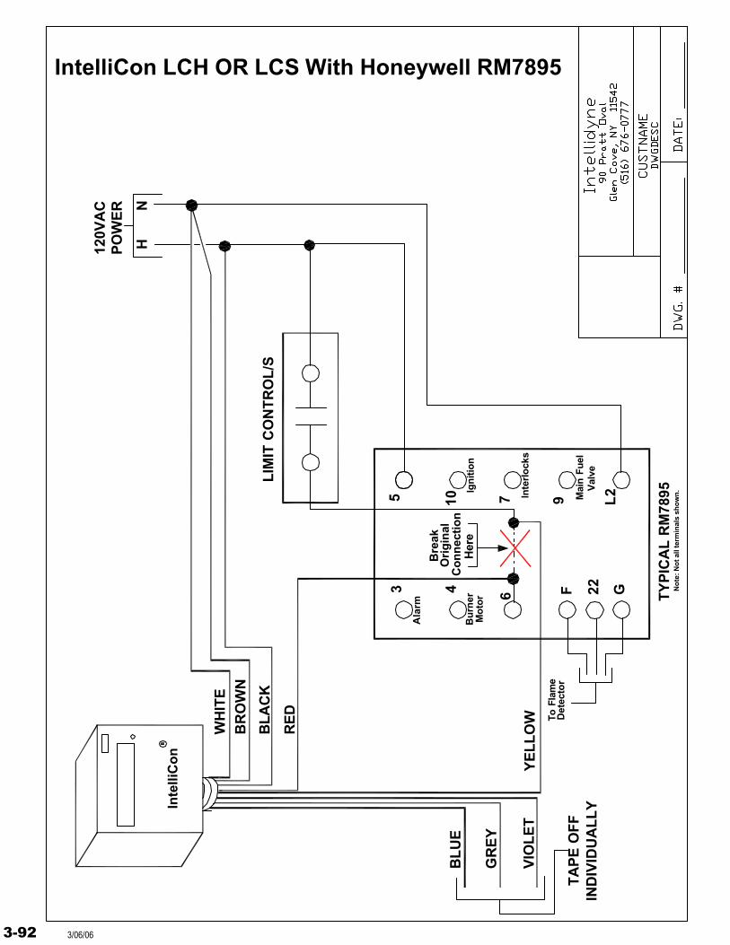
IntelliCon LCH OR LCS With Honeywell RM7895
3 4 6 F G
5 10 7 L29
HN
120V
AC
PO
WE
R
TY
PIC
AL
RM
7895
LIM
IT C
ON
TR
OL
/S
Bu
rner
Mo
tor
Ala
rm
Ign
itio
n
Inte
rlo
cks
Mai
n Fu
elV
alve
To F
lam
eD
etec
tor
Bre
ak
Her
e
Ori
gin
alC
on
nec
tio
n
Inte
lliC
on
WH
ITE
BR
OW
N
BL
AC
K
RE
D
YE
LL
OW
BL
UE
GR
EY
VIO
LE
T
TA
PE
OF
FIN
DIV
IDU
AL
LY
No
te: N
ot a
ll te
rmin
als
sho
wn
.
22
3-92 3/06/06
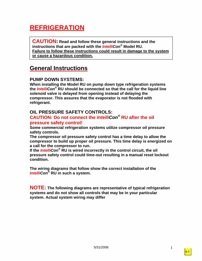
5/31/2006 1
REFRIGERATION General Instructions PUMP DOWN SYSTEMS: When installing the Model RU on pump down type refrigeration systems the IntelliCon® RU should be connected so that the call for the liquid line solenoid valve is delayed from opening instead of delaying the compressor. This assures that the evaporator is not flooded with refrigerant. OIL PRESSURE SAFETY CONTROLS: CAUTION: Do not connect the IntelliCon® RU after the oil pressure safety control! Some commercial refrigeration systems utilize compressor oil pressure safety controls. The compressor oil pressure safety control has a time delay to allow the compressor to build up proper oil pressure. This time delay is energized on a call for the compressor to run. If the IntelliCon® RU is wired incorrectly in the control circuit, the oil pressure safety control could time-out resulting in a manual reset lockout condition. The wiring diagrams that follow show the correct installation of the IntelliCon® RU in such a system. NOTE: The following diagrams are representative of typical refrigeration systems and do not show all controls that may be in your particular system. Actual system wiring may differ
CAUTION: Read and follow these general instructions and the instructions that are packed with the IntelliCon® Model RU. Failure to follow these instructions could result in damage to the system or cause a hazardous condition.
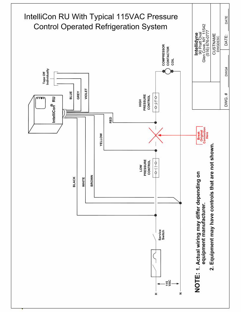
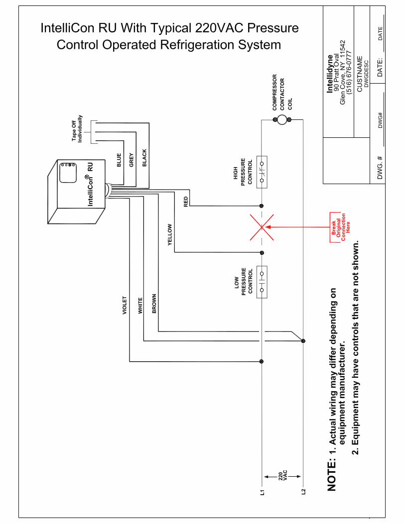
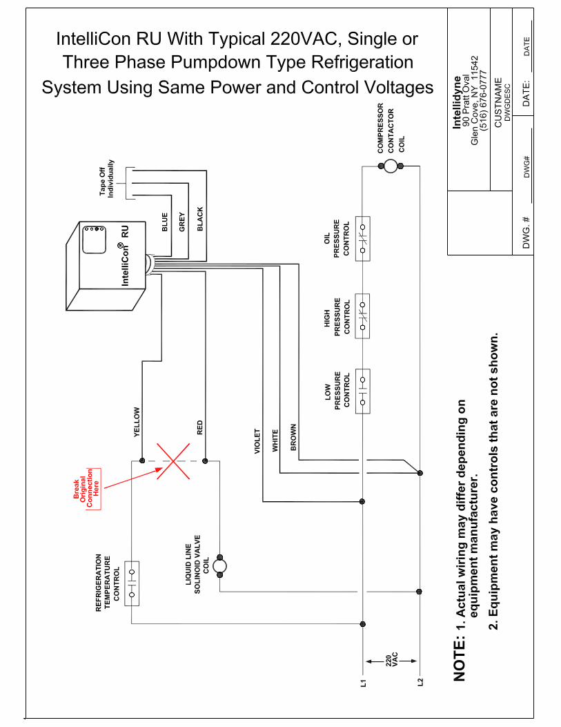

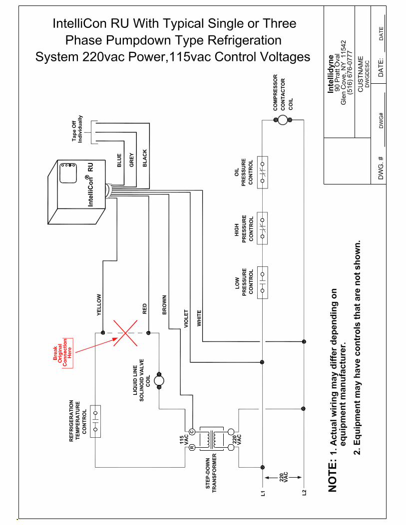
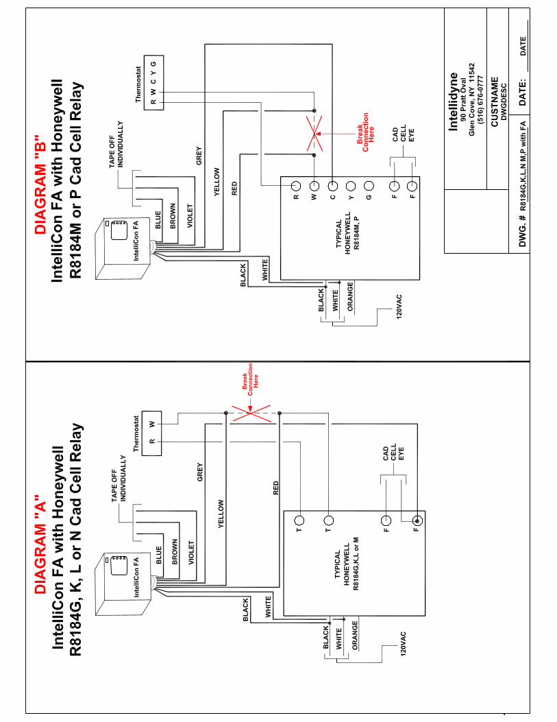
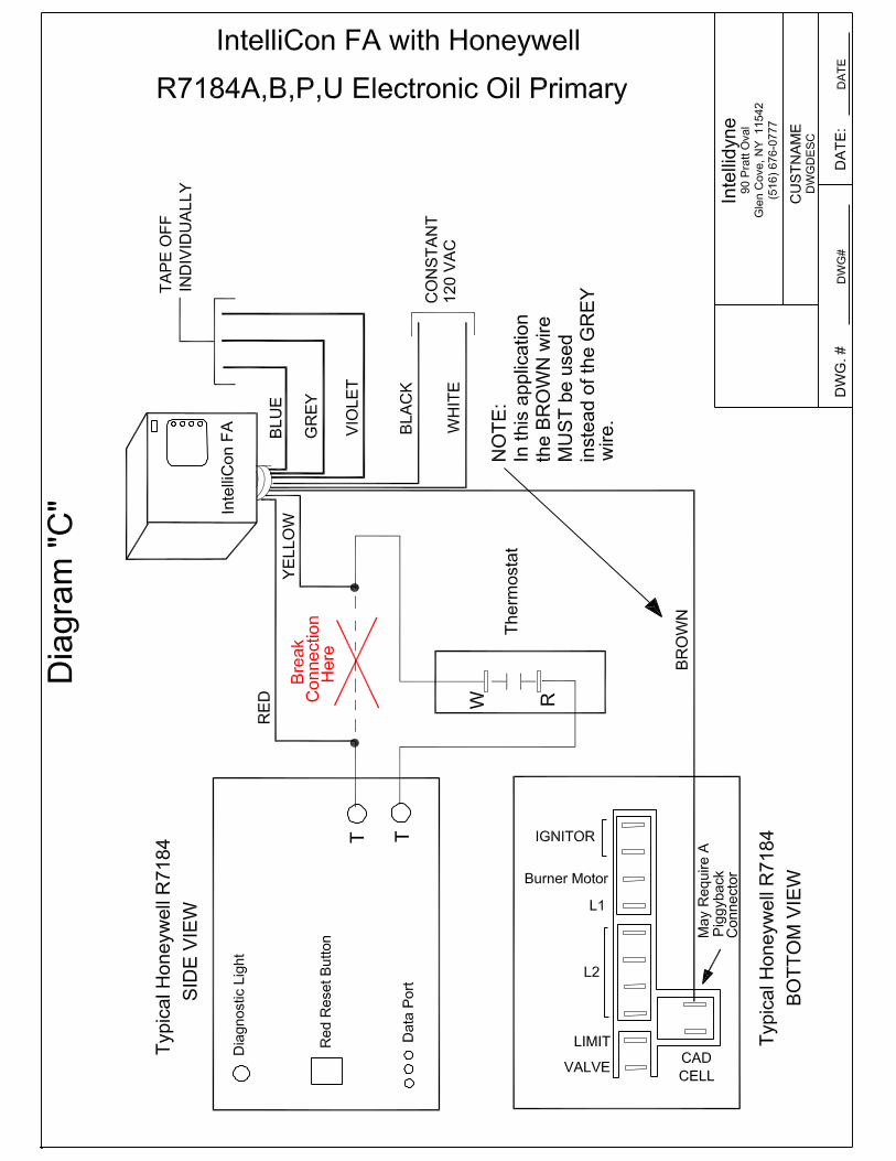
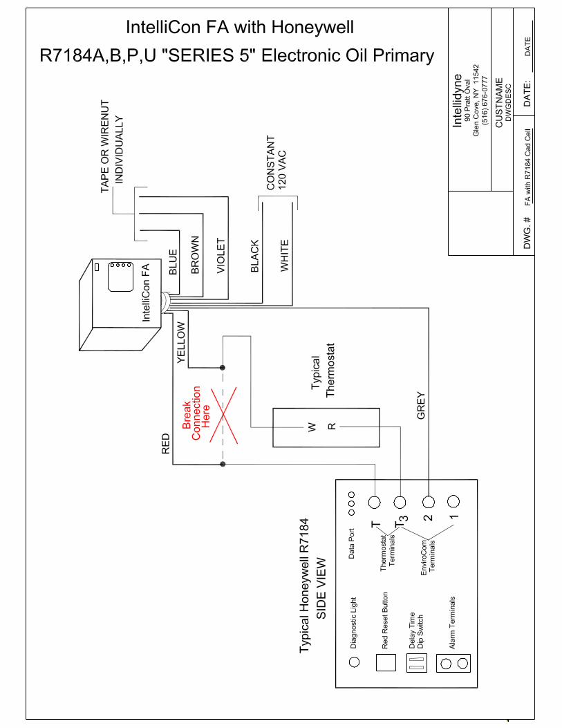
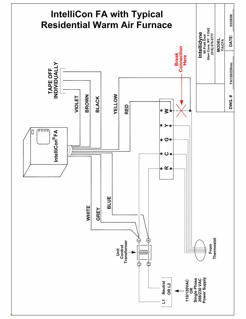
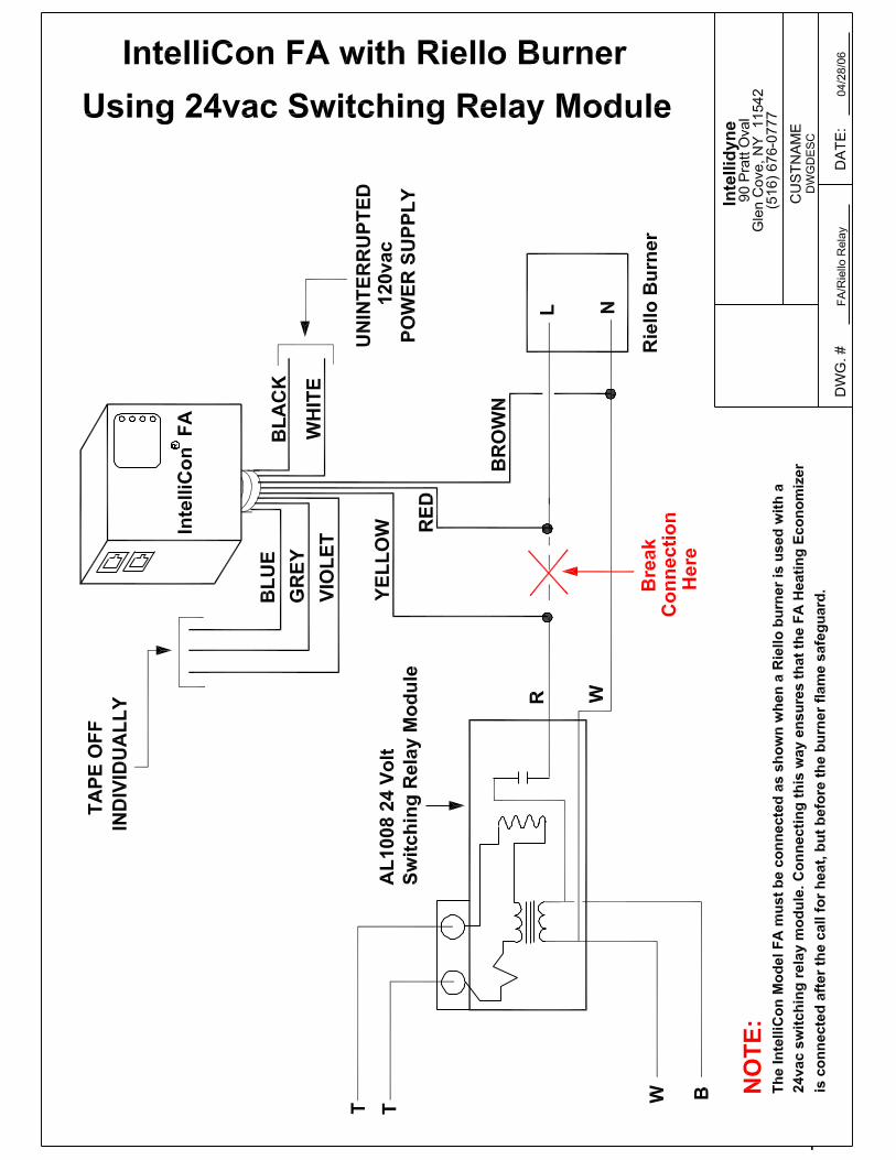
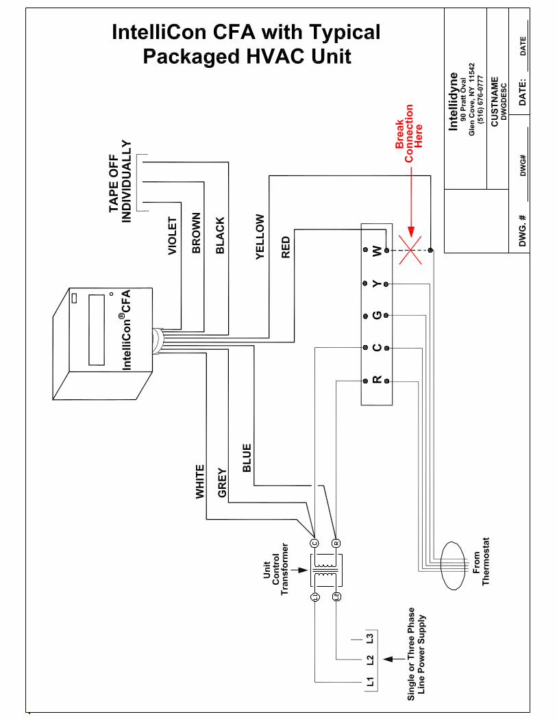

NOTES
3/06/06

NOTES
3/06/06

NOTES
3/06/06

NOTES
3/06/06
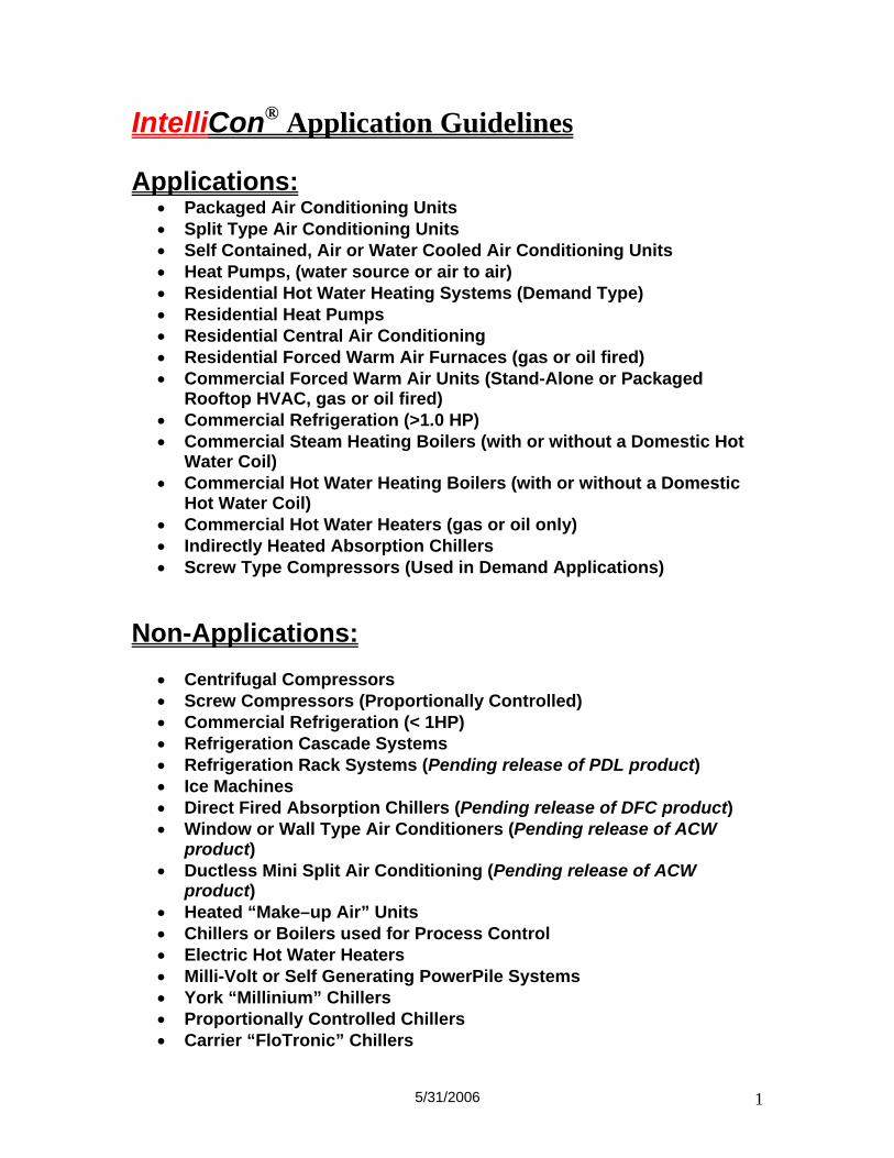
5/31/2006 1
IntelliCon® Application Guidelines
Applications: • Packaged Air Conditioning Units • Split Type Air Conditioning Units • Self Contained, Air or Water Cooled Air Conditioning Units • Heat Pumps, (water source or air to air) • Residential Hot Water Heating Systems (Demand Type) • Residential Heat Pumps • Residential Central Air Conditioning • Residential Forced Warm Air Furnaces (gas or oil fired) • Commercial Forced Warm Air Units (Stand-Alone or Packaged
Rooftop HVAC, gas or oil fired) • Commercial Refrigeration (>1.0 HP) • Commercial Steam Heating Boilers (with or without a Domestic Hot
Water Coil) • Commercial Hot Water Heating Boilers (with or without a Domestic
Hot Water Coil) • Commercial Hot Water Heaters (gas or oil only) • Indirectly Heated Absorption Chillers • Screw Type Compressors (Used in Demand Applications)
Non-Applications:
• Centrifugal Compressors • Screw Compressors (Proportionally Controlled) • Commercial Refrigeration (< 1HP) • Refrigeration Cascade Systems • Refrigeration Rack Systems (Pending release of PDL product) • Ice Machines • Direct Fired Absorption Chillers (Pending release of DFC product) • Window or Wall Type Air Conditioners (Pending release of ACW
product) • Ductless Mini Split Air Conditioning (Pending release of ACW
product) • Heated “Make–up Air” Units • Chillers or Boilers used for Process Control • Electric Hot Water Heaters • Milli-Volt or Self Generating PowerPile Systems • York “Millinium” Chillers • Proportionally Controlled Chillers • Carrier “FloTronic” Chillers

3/06/06


![[Harish, A.R. Sachidananda, M.] Antennas and Wave](https://img.pdfslide.us/doc/110x75/55cf93bb550346f57b9e37a9/harish-ar-sachidananda-m-antennas-and-wave.jpg)