Embed Size (px)
Citation preview

Manual WS.500 v4 2‐Wire Energy Monitor
1
2‐WIRE WS.500 ENGLISH MANUAL
1. Overview 2. Bus structure 3. Startup 4. Network settings 5. Mail settings
6. Upgrading 7. Energy prices 8. Login ‐ password 9. Programming modules
10. Logic alarm via email
11. Layout
12. EPC level
13. Control
14. Graphs
15. Sub totals
16. Logging to ftp server
17. Data transfer via HTTP
18. Quick start
19. Troubleshooting

Manual WS.500 v4 2‐Wire Energy Monitor
2
1. OVERVIEW
The 2‐WIRE Web WS.500 offers a lot of opportunities to make logging and visualization of data
possible. What type of data, there may be all kinds:
Measurement of electrical loads: voltage, current, power, reactive power, power factor,
consumption.
Thermostat values: pre‐set (heating, cooling, ventilation), set point, room temperature, fan
speed.
Air sensor values: temperature, humidity, CO2, VOC.
Counting impulses from energy meters such as gas, electricity and water meter.
Measuring energy consumption on devices with fix power on a time basis. (Ex. water heater,
heating oil burners, lights ...)
Alerts to mailbox when crossing power consumption, temperature control
On the web pages to view all log values of the modules in graphs, per hour, per day or per year,
together with the costs of that year.
Also subtotals are calculated, which can be imported into different formats.
Features WS.500:
DIN rail module (2 modules wide)
Power supply: 15V / 1A
Bus connection: 2‐WIRE (up to 500mA) and MODBUS (up to 32 modules.)
Ethernet connectivity with integrated transformers
Network processor 10 / 100Mbit / sec
Real Time Clock with backup battery, daily put in sync with NTP server
Flash Memory 8Mb
4Gb SD card (backup configuration data and logs 3 years)
Upgrading via FTP server 2‐WIRE
64 log channels, each up to five readings (32bits) and 2 consumption values (import‐
export)
Communication every minute to the connected modules for reading the measurements
Logging every minute to SD of five measurements per channel, and every 5 mins 2
consumption values
Energy consumption cost calculation (estimate NOT FOR CLEARANCE !!)
EPC level calculation (kWh / m2)
Web HTML: 4 + 1 user administrator can simultaneously use the server.
set login, password and language (NL‐FR‐EN‐DU) per user.
IP address fix or dynamically via DHCP server
Domain name instead of IP address via DNS server
Full configuration of all modules, create groups for layout
Manual WS.500 v4 2‐Wire Energy Monitor
3
FTP client: Setting rhythm for logging data to remote FTP server separately adjustable for
real‐time measurement (interval per minute to 60 minutes) and for consumption
measurements (interval by 5min until 24h). The format is CSV delimited '|', but can also
be the AMR format MMR (BE: EANDIS). Each file has a unique name and can be
incorporated into your own remote database.
HTTP request: Via an instruction request all readings and consumptions per channel from
a selected time and a certain period of time (1 day to 31 days). The format is also JSON
and can be split easily (ex. Excel).
Online control or request statuses ex. relay outputs, thermostat can also be controlled
via an HTTP request.
2. BUS STRUCTURE
The WS500 has two bus systems on board: a 2wire bus according to the 2‐WIRE protocol, and a
3‐ or 4 wire bus according to the RS485 MODBUS standard
PC.080: 2‐wire: BUSTERMINAL 1 (GND) and BUSTERMINAL 4 (VDD)
EMM630 ‐ ACQ.CO2 – TFC.01: BUSTERMINAL 2(A) and BUSTERMINAL 3 (B)
EMM120‐EMM220: BUSTERMINAL 1(GND), BUSTERMINAL 2(A) and BUSTERMINAL 3 (B)
EC.441: BUSTERMINAL 1(GND), BUSTERMINAL 2(A), BUSTERMINAL 3(B) and
BUSTERMINAL 4(VDD)
Between the terminals A‐B there must be placed the provided resistors (120 ohms) at both ends of
the bus!! Recommended is EIB bus cable (4 core)
More information: please consult documentation modules!
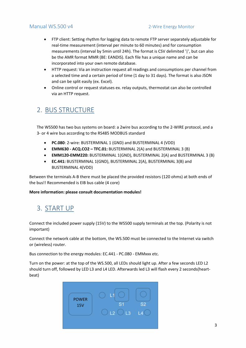
3. START UP Connect the included power supply (15V) to the WS500 supply terminals at the top. (Polarity is not
important)
Connect the network cable at the bottom, the WS.500 must be connected to the Internet via switch
or (wireless) router.
Bus connection to the energy modules: EC.441 ‐ PC.080 ‐ EMMxxx etc.
Turn on the power: at the top of the WS.500, all LEDs should light up. After a few seconds LED L2
should turn off, followed by LED L3 and L4 LED. Afterwards led L3 will flash every 2 seconds(heart‐
beat)
L1
S1 S2
L2 L3 L4
POWER
15V
Manual WS.500 v4 2‐Wire Energy Monitor
4
Down where the network cable is plugged in, there should light a green LED, and frequently an
orange LED. Then the network is OK.
If EC.441 or PC.080 modules are connected, the power led of these modules should light up.
4. NETWORK SETTINGS By default, the WS500 is configured to "DHCP" which means that at the first boot thee webserver
gets automatically assigned an IP address by your router. To find out the address, there are programs
that show the IP address. You can also download a server‐scanner on the 2‐WIRE website:
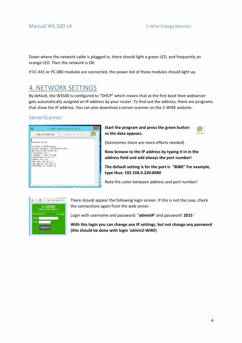
ServerScanner:
Start the program and press the green button
so the data appears.
(Sometimes there are more efforts needed)
Now browse to the IP address by typing it in in the
address field and add always the port number!
The default setting is for the port is "8080" For example,
type thus: 192.168.0.220:8080
Note the colon between address and port number!
There should appear the following login screen. If this is not the case, check
the connections again from the web server.
Login with username and password: "adminIP' and password' 2015 '
With this login you can change any IP settings, but not change any password
(this should be done with login 'admin2‐WIRE)

Manual WS.500 v4 2‐Wire Energy Monitor
5
HARD RESET to a fixed IP address When there are problems with DHCP (ex. your router has no IP address), and the Server Scanner still cannot find a Web server, despite a decent network connection, you can decide to go to a "default" fixed IP address:
Procedure: Power off the WS500, wait 5 seconds, push button 2 and hold, turn on power, and continue to press until the LED starts to flash. Keep on pushing for another 3 seconds and then release. After about 5 seconds all LEDs are off and the WS500 is now at a fixed IP address. Now you need to "browse" to the default IP address: 192.168.0.123:8080
Note: This address is not always reachable for the network where your PC or laptop is connected to. When you are in a different range, you need to change the network settings of your PC! Further explanations can be found in "TROUBLESHOOTING"
Once logged in:
Click on 'Configuration', then appear the following menus:

Manual WS.500 v4 2‐Wire Energy Monitor
6
Starting with 'SETTINGS'. We start with checking the network settings. This is as said standard DHCP.
Do you want to fix the address, or assign a different address or port number, check out "DHCP" and
fill in your address and port number.
Example:
192.168.0.123 and the port number
8080.
Note that if you change this address,
you should write down exactly what is
the new address and port number!
After sending you have no longer
communication and you have to start
the browser with the new IP address
and port number.
Press ‘SEND CONFIG’
After a second confirmation ( in RED) you have to enter in the toolbar of your browser the new
address and port number. If you have communication, the new setting is successful.
Now we have to browse to 192.168.0.123:8080 and then the address successfully setting.
DHCP: automatically assign an IP address via a DHCP server "
Check the 'DHCP' and press' SEND CONFIG.

Manual WS.500 v4 2‐Wire Energy Monitor
7
After a short time, a new IP address is assigned to your Web server. (In this example 192.168.0.164:
8080)
Make a note of this new address and press the button to confirm.
As from now there is no communication on your old IP address. Type in the toolbar, the newly
assigned address to recover connection.
Go back to "SETUP" ‐> "SETTINGS"
There has to be Internet available on your web server, otherwise there are no visible graphics, and
you cannot send logs to a remote FTP server.
"GATEWAY": Normally this is the first 3 digits of your IP address, and the last number '1'. (Ex, your IP
address is 192.168.0.123, then the GATEWAY 192.168.0.1)
If you do not fill in this properly, there is no internet possible on your web server.
'SUBNET MASK': default is set to 255.255.255.0
This should only be changed if the Web server is connected to an extensive (sometimes industrial)
network. These settings you will then get notified by your IT technicians.
"DNS SERVER": automatically filled in when you checked on ‘DHCP’. This usually works when you
type in the same IP address as your gateway. (Eg 192.168.0.1)
LOGS TO FTP‐SERVER: It is also possible that you want to send the log data to a remote FTP server. For this we have to work
with an IP address, either with a 'domain'. The port number is always "21" (eg 78.22.222.111:21))
Manual WS.500 v4 2‐Wire Energy Monitor
8
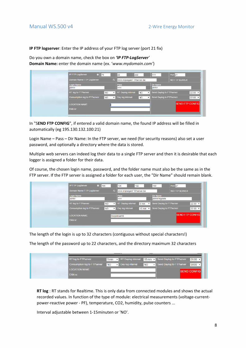
IP FTP logserver: Enter the IP address of your FTP log server (port 21 fix)
Do you own a domain name, check the box on ‘IP FTP‐LogServer’
Domain Name: enter the domain name (ex. ‘www.mydomain.com’)
In "SEND FTP CONFIG", if entered a valid domain name, the found IP address will be filled in
automatically (eg 195.130.132.100:21)
Login Name – Pass – Dir Name: In the FTP server, we need (for security reasons) also set a user
password, and optionally a directory where the data is stored.
Multiple web servers can indeed log their data to a single FTP server and then it is desirable that each
logger is assigned a folder for their data.
Of course, the chosen login name, password, and the folder name must also be the same as in the
FTP server. If the FTP server is assigned a folder for each user, the "Dir Name" should remain blank.
The length of the login is up to 32 characters (contiguous without special characters!)
The length of the password up to 22 characters, and the directory maximum 32 characters
RT log : RT stands for Realtime. This is only data from connected modules and shows the actual
recorded values. In function of the type of module: electrical measurements (voltage‐current‐
power‐reactive power ‐ PF), temperature, CO2, humidity, pulse counters ...
Interval adjustable between 1‐15minuten or 'NO'.

Manual WS.500 v4 2‐Wire Energy Monitor
9
RT Daylog interval: Once per day, the webserver can send at a chosen time, the complete data
from the previous day, with an interval that can be chosen between 1 and 60minutes.
Send Daylog: time of day to transmit all RT‐logs.
ConsumptionLog: direct forwarding consume to the FTP server at a specified interval.
Day Log Interval: One can also send daily at a chosen time the complete data from the previous
day, with an interval that can be selected between 5 minutes and 24 hours.
Send Daylog: time of day to transmit all consumption logs.
Location Name: All logs are named "Location Name" and get a date stamp. The same “location
name” will also be send with the mails from 'Alerts'. See later
5. MAIL SETTINGS "Alerts for exceeding limits on consumption and temperatures should be set up in the configuration
of the modules . If you have an account with a provider, you can fill in the outgoing mail server
address (eg. Uit.telenet.be) and your email address (sender address).
The alerts can be sent to up to two addresses. (Mail Address1 and 2)
6. UPGRADING: The next compartment is used for upgrading the server and the 2‐WIRE modules. The condition for
this function is of course that the webserver is connected to the Internet.
At 2‐WIRE we have a server where are the necessary upgrade files can be downloaded from. To
check whether upgrading is needed, one can press the button "FIRMWARE VERSIONS"
When the connection with the 2‐WIRE Upgrade Server succeeds, you can see the different firmware
versions available. (Sometimes a second attempt be possible if the server 'occupied'.)
Manual WS.500 v4 2‐Wire Energy Monitor
10
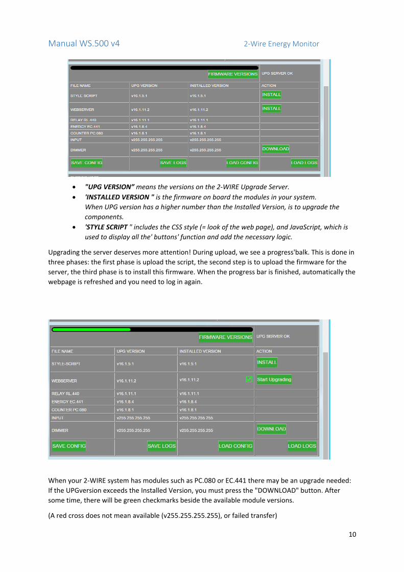
"UPG VERSION” means the versions on the 2‐WIRE Upgrade Server.
'INSTALLED VERSION " is the firmware on board the modules in your system.
When UPG version has a higher number than the Installed Version, is to upgrade the
components.
'STYLE SCRIPT " includes the CSS style (= look of the web page), and JavaScript, which is
used to display all the' buttons' function and add the necessary logic.
Upgrading the server deserves more attention! During upload, we see a progress'balk. This is done in
three phases: the first phase is upload the script, the second step is to upload the firmware for the
server, the third phase is to install this firmware. When the progress bar is finished, automatically the
webpage is refreshed and you need to log in again.
When your 2‐WIRE system has modules such as PC.080 or EC.441 there may be an upgrade needed:
If the UPGversion exceeds the Installed Version, you must press the "DOWNLOAD" button. After
some time, there will be green checkmarks beside the available module versions.
(A red cross does not mean available (v255.255.255.255), or failed transfer)

Manual WS.500 v4 2‐Wire Energy Monitor
11
The modules are thus not upgraded yet! This should be done in menu 'Modules' ‘MODULES’
At the bottom there are 4 buttons: These serve as a backup of your configuration and logs to SD:
SAVE CONFIG: save configuration to SD (this happens automatically every night at 3 am)
SAVE LOGS: Keep all energy logs to SD (happens automatically every night at 3 am)
LOAD CONFIG: This button can be used if you want to reset the configuration to the last,
last saved copy. (For example, you delete a module, or channels incorrectly filled in).
Keep in mind that if you made a backup yet, this is dated the same day, at 3am!
With this we do not need to re‐enter all data. The password = 'admin2‐WIRE.
Note: The setting of IP address, login and passwords are NOT stored on the SD!
LOAD LOGS: USE ONLY at replacement of the server, same as above!
(The energy logs are thus put back to the last backup (at night at 3am)

Manual WS.500 v4 2‐Wire Energy Monitor
12
7. ENERGY PRICES As already mentioned, we can (approximate) calculate the daily energy consumption and there is a
price tag attached to them. When we know what the cost is for gas, water electricity, we can
complete this table below. There are two pricelevels for electricity (day ‐ and night consumption).
Everything must be filled in cents, so DO NOT DECIMAL!!
"SEND" because the values are entered.
NB. Tariff changes you can always change, every day is calculated what your consumption costs was
the inspired fare, and so is stored in the database. Enter your other values in afterwards, this will
have no effect on the previous calculations.
8. LOGIN
The last section in the SETTINGS tops, and is certainly not unimportant:
login ‐ password
LOGIN: The WS.500 can simultaneously work with 4 users. Each user can choose a login name (up to 16 characters), a password (always four digits) and a language version.
Only logged in as administrator, with password "admin 2‐WIRE ' , you can make changes here!
When we start up the first time we see: "USERS": 0
The administrator is not counted in the 4 users, the administrator usually serves only to modify the
configuration so that other users can not make changes. (So do not sprinkle around the admin login
name and password ...) The login name admin2‐WIRE " or ’adminIP’ can never be changed, but you
can change the password (2015).

Manual WS.500 v4 2‐Wire Energy Monitor
13
Change password of the administrator:
Type in the filed "LOGIN OLD 'and' PASS OLD ' the current login name (admin2‐WIRE) and password.
Type in "LOGIN NEW 'back' admin2‐WIRE" and "PASS NEW 'your new password (4 digits)
Press 'SENDPASS' to send the new data.
The same applies to newly created users:
Enter to “LOGIN OLD” 'loginold' and “PASS OLD” 1234
At “LOGIN NEW” now the user name (up to 16 characters) and “PASS NEW” password (4 digits)
The 'TIMEOUT' serves to set the expiry time of your login. When there are actions with the web
server this time is restarted every time. If there are no further actions, and the expiration time has
passed, it should be re‐signed.
Adjustable between 1 and 255u. 0 means 30 days’ expiry time.
The language version is a user adjustable and serves for the fixed texts on your web server.
Not all texts have been translated. Some are difficult to translate and are usually displayed in English.
Press 'SENDPASS' to confirm.
When sending the login we always return to the boot menu. We now need to login again to confirm
who you are.
Example:

Manual WS.500 v4 2‐Wire Energy Monitor
14
To remove a user is doing it the other way:
At “LOGIN OLD” comes his username, his password at “OLD PASS”.
At “LOGIN NEW” coming now 'loginold' and “PASS NEW “1234
Press 'SENDPASS' to confirm.
NB. From v6.3 can also retrieve the login and password on the next field "USERS" to enter a number
between 1 (user1) and 5 (admin). The data from each user are displayed.
9. MODULE PARAMETERS
Choose the menu 'Modules' Left we see a number of text boxes, and a few notes:
'NEW': entering new Serial
'CHANGE': change the module name (not channel name!) or serial number
'DELETE': Delete selected module
"CANCEL": undo changes if it had not been sent.
'SEND': Forward module to Web server
"DOWNLOAD": back load the previous configuration of the selected
module, provided that the changes had not yet been sent.
"UPGRADE": only active if modules are with 2‐WIRE protocol
To start, we must first complete a "serial number" at the place where we see "Serial No.". The serial number always consists of two figures, one uppercase letter, and returned five digits. These have a meaning:
A = Air quality meter = AQM.CO2
C = Counter module PC.080
D = Dimmer Module (not yet available)
E = Energy meter = EMM.120 ... 630 series
T = Temperature = TFC.01
M = Modbus energy counter EC.441
P = expansie (dummy)module voor EC.441 slimme meter Poort
Serial numbers:
These modules have a fixed serial number assigned by 2‐WIRE and this number
is printed on the module: PC.080, EC.441.
Other modules such EMM.120 ... 630 do not have SerialNr but only a Modbus addresses (range 1‐
247). Still there can only be worked with SerialNrs in programming.
Manual WS.500 v4 2‐Wire Energy Monitor
15
Therefore, we will create fictive serial numbers. Most modules require only one channel, except for
the more complex modules such as EMM.630, it has 3 channels required (= 3 phases)
Each serial number:
The first two digits of the serial number will be:
'01' for single phase meters, thermometers, CO2
'03' for three‐phase meters
The meaning of the letter‐character has already been discussed.
The next five digits dialing yourself, but make sure that the serial number "unique" continues!
Examples of the series EMMxxx energy Modbus meters:
Single‐phase (import only): EMM120 ‐ EMM220: 01E00001 ... .01E99999
Single‐phase (import + export): EMM220: 02E00001 … 02E99999
Three‐phase: EMM630 ‐ EMM630CT: 03E00001 ... 03E99999
Thermostat TFC.01: 01T00001 ... 01T99999
AirQuality AQM.CO2: 01A00001 ... .01A99999
The limit on the number of log channels is 64, and the limit of the number of modules is 32.
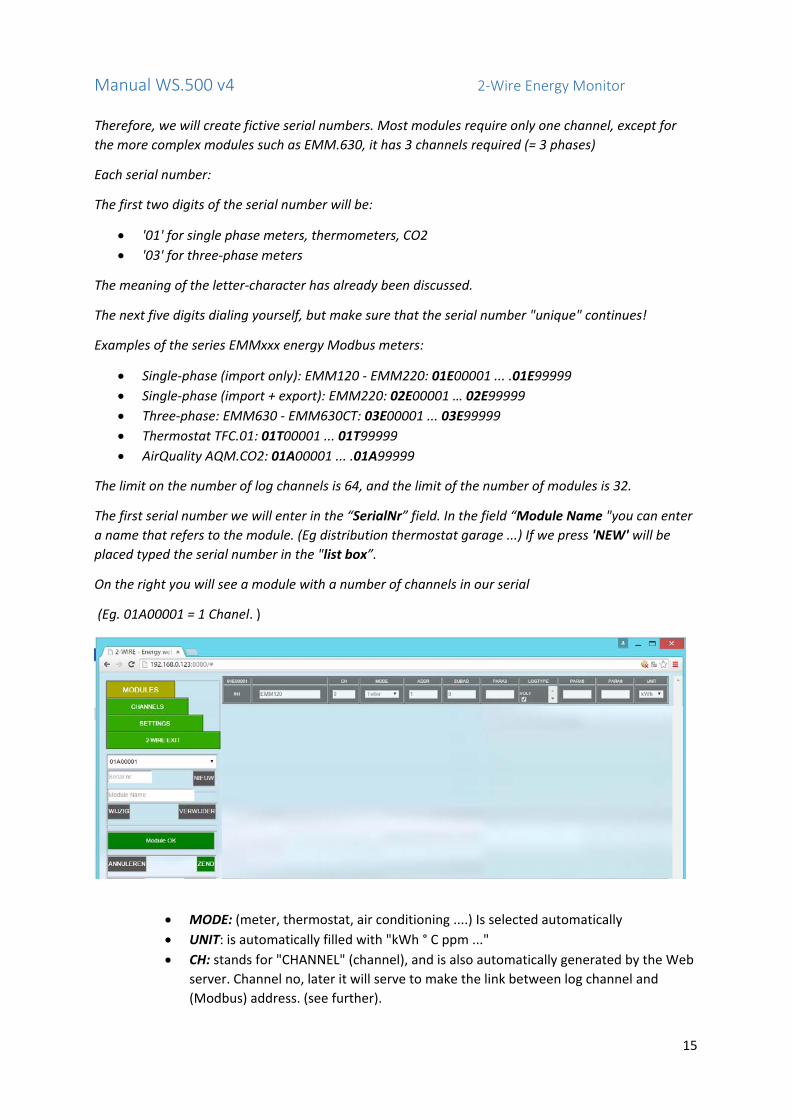
The first serial number we will enter in the “SerialNr” field. In the field “Module Name "you can enter
a name that refers to the module. (Eg distribution thermostat garage ...) If we press 'NEW' will be
placed typed the serial number in the "list box”.
On the right you will see a module with a number of channels in our serial
(Eg. 01A00001 = 1 Chanel. )
MODE: (meter, thermostat, air conditioning ....) Is selected automatically
UNIT: is automatically filled with "kWh ° C ppm ..."
CH: stands for "CHANNEL" (channel), and is also automatically generated by the Web
server. Channel no, later it will serve to make the link between log channel and
(Modbus) address. (see further).

Manual WS.500 v4 2‐Wire Energy Monitor
16
ADDR: Each channel must have a unique address in the range 1‐247. So no channel
can have the same address. Start from number 1 and so on, so that each
measurement input has a unique address. The simplest is to 'ADDR' to complete the
same value as the channel number 'CH'. When we have no serial modules (series
EMMxxxx) we have to program these addresses on these modules via the existing
display on the EMM module itself. (How to change the address on the MODBUS
module is described in the manual of the module itself.)
SUBADD: for PC080 modules and EC441: see manual of these modules.
For the EMMxxxx series:
Serial 01Exxxx: sub add = 0
Serial 02Exxxx: both channels SAME ADDRESS, sub add 0‐1
Serial 03Exxxx: all three channels SAME ADDRESS, sub add = 0, ‐ 1 – 2
PARA3: PARA6: specifically explained in the manual of the module EC441 or PC080.
For EMMxxx should be completed nothing.
Log type: This is for those who want to send the log data to a remote FTP server (see
Section 9).. You can check which log types you want.
NB. The log types are dependent on the type of module, and will always be logged to SD every
minute, even if nothing is checked!
An overview on ‘MODE’ ‘LOGTYPE‘ and ‘UNIT’:
TYPE MODULE MEANING MODE LOGTYPE UNIT
A AQM.CO2 CO2 measure AirQ roomtp °C
RH %
CO2 ppm
VOC 0‐3
E EMM.120/220 electr.power Teller Voltage V
Current mA
Power W/Var
power factor ‐‐
Consumption import kWh+
Consumption export kWh‐
C‐M EC.441 Counter module Teller Voltage V
Current mA
PC.080 Power W
Consumption kWh
T TFC.01 thermostat Temp roomtp °C
setpoint °C
regime 0‐2
fan speed 0‐3
We assume that the EMM modules are on the display assigned a unique MODBUS address. Note
down these addresses and the group or circuit with which this module is connected. Give it a name
(eg lighting above, sockets living room, stove, etc ..)

Manual WS.500 v4 2‐Wire Energy Monitor
17
If the Modbus module is connected to the RS485 bus, and there is power to the module, you can
press 'SEND'. In "Module OK" you know that communication, the address and the power supply is in
order. If not, check power, address and bus connection (A and B do not confuse?)
(The address can be checked on the module via the display on the EMM120‐220‐630, see instructions
for the module)
Note: You can enter or modify only one module at a time. Do you want to continue with new
modules, you must first press "SEND" button when it was changed to red light.
If you want to change an existing module, do not type in the SerialNr but select it from the "list box.
A change, if not yet sent can also be cancelled (“CANCEL”) or return to the previous setting by
pressing the "
DOWNLOAD".
When all modules have been introduced and the communication was fine, a brief explanation in case
changes should be made.
A module that you want to change can be done by selecting the serial number in the 'list box:
THEREFORE, DO NOT retype the serial number!
Now you can only make changes in this module. (The other modules are 'locked' to prevent that you
can change anything in the wrong module.)
After changing a text or number, you should always confirm with 'ENTER': Click any other cell, so you
stand outside the cell in which you have made changes. Now, again the "SEND" button will light red.
If any changes are made, click "SEND".
If you forget to give a name to the module, which serves as a 'helping hand', select this serial
number in the 'list box and press' CHANGE'.
Manual WS.500 v4 2‐Wire Energy Monitor
18
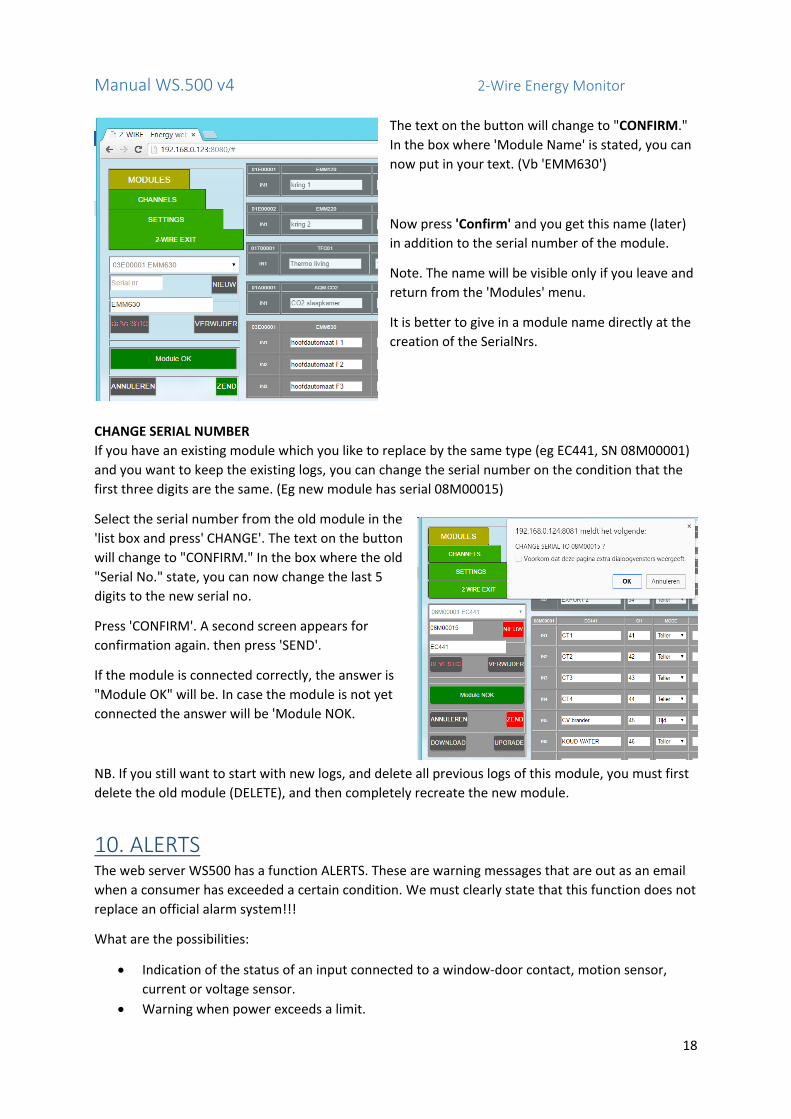
The text on the button will change to "CONFIRM."
In the box where 'Module Name' is stated, you can
now put in your text. (Vb 'EMM630')
Now press 'Confirm' and you get this name (later)
in addition to the serial number of the module.
Note. The name will be visible only if you leave and
return from the 'Modules' menu.
It is better to give in a module name directly at the
creation of the SerialNrs.
CHANGE SERIAL NUMBER
If you have an existing module which you like to replace by the same type (eg EC441, SN 08M00001)
and you want to keep the existing logs, you can change the serial number on the condition that the
first three digits are the same. (Eg new module has serial 08M00015)
Select the serial number from the old module in the
'list box and press' CHANGE'. The text on the button
will change to "CONFIRM." In the box where the old
"Serial No." state, you can now change the last 5
digits to the new serial no.
Press 'CONFIRM'. A second screen appears for
confirmation again. then press 'SEND'.
If the module is connected correctly, the answer is
"Module OK" will be. In case the module is not yet
connected the answer will be 'Module NOK.
NB. If you still want to start with new logs, and delete all previous logs of this module, you must first
delete the old module (DELETE), and then completely recreate the new module.
10. ALERTS The web server WS500 has a function ALERTS. These are warning messages that are out as an email
when a consumer has exceeded a certain condition. We must clearly state that this function does not
replace an official alarm system!!!
What are the possibilities:
Indication of the status of an input connected to a window‐door contact, motion sensor,
current or voltage sensor.
Warning when power exceeds a limit.

Manual WS.500 v4 2‐Wire Energy Monitor
19
Warning when the daily consumption exceeds a limit.
Monitoring temperatures if upper or lower limit is reached.
The WS500 can be filled up with to 2 email addresses, which receive these messages.
For the programming the PC.080 we have to complete a number of parameters according to the
mode.
At the parameter‐field 'ALERT' (= ALARM) we determine the logic that is to be followed:
The maximum number of characters is 5, the first character contains the logic, and the other
characters must be digits from 0 up to 9999. Exceptions are temperatures with lower and upper limit
where we will place a letter between two values (see below)
In function of the chosen MODE we use letters that determine the "logic":
Input contacts: A followed by an on‐delay 0‐9999 sec
Power limit: p (power) for capacity up to 9999 W
Power limit: P for larger capacity up to 9999 kW
daily consumption limit: c (consumption) for consumption up to 9999 Wh
daily consumption limit: C for large consumption up to 9999 kWh
Temperature: see below in Table temperatures
The possibilities per Type explained in a table below:
1. STATUS TRACKING: The alert function is activated by the letter 'A' for input contacts.
FUNCTION: MODE PARA3 ALERT PARA6
Track status of the connected input
Alway’s bi‐stable
Type contact:
Delay ON
Delay OFF
Pushbutton with ‘toggle’ function (PB)
Bi‐stable 0 Ex. A10 (10 sec delay)
Ex. 120 (120 sec delay)
Contact normal open (NO)
Bi‐stable 1 Ex. A0 (no delay)
VEx. 5 (5 sec delay)
Contact normal closed (NC)
Bi‐stable 2 Ex. A500 (500 sec delay)
Ex. 0 (no delay)
Example email with warning:
2. POWER LIMIT: The alert function is activated by entering the letter "p" or "P" (power) in the
alert field.

Manual WS.500 v4 2‐Wire Energy Monitor
20
When the power of the connected meters exceeds longer than one hour the limit, an email is sent
with the data set limit and measured value.
At midnight, the measurement is restarted for a new evaluation.
FUNCTION: MODE ALERT
Warning high power Always counter
Power Limit (W of kW)
Power up to max 9999 W (Resolution 1 W)
Counter Ex. p1000 (Border 1000 W)
Power up to max 9999 kW (Resolution 1 kW)
Counter Ex. P10 (Border 10 kW)
Example of a received mail:
3. DAILY CONSUMPTION LIMIT: the alert function is activated by the letter "c" or "C"
(consumption). If the daily consumption of connected meters goes above this limit during the
day, an email is sent with the data set limit and measured value.
At midnight, the measurement is restarted. This results in maximum 1 message per day.
FUNCTION: MODE ALERT
Warning 1 day consumption Counter Consumption limit(max 9999 Wh)
Consumption up to max 9999 Wh (resolution 1 Wh)
Counter Ex. c1500 (limit 1500 Wh)
Consumption up to max 9999 kWh (resolution 1 kWh)
Counter Vb. C30 (limit 30 kWh)

Manual WS.500 v4 2‐Wire Energy Monitor
21
Example warning day consumption goes above a limit of 15 kWh:
4. TEMPERATURE LIMIT:
Temperatures can be very important, and in some applications you want to follow this closely.
Examples fridge‐freezer monitoring, risk of frost, over‐temperature boiler ...
Therefore, it is also here to introduce a (limited) logic for measuring values of ‐15 ° C to + 85 ° C
Note. All limits can only be full integers, so half a degree is not possible!
There is a fixed delay of 30 minutes before an alert is possible.
If there has been an alert, we can set the waiting time before there will be a new alert possible. In
'PARA6' will be placed this time. The waiting period must be at least 30 minutes, and can go up to
1440 minutes (= 24 hours). 0 means only 1x per day alert.
The options are:
Alert when the temperature drops below the set value
Alert when the temperature is HIGHER than the set value
Alert when the temperature falls below the minimum limit OR HIGHER than the maximum
limit.
Keep in mind that negative temperatures are possible, and ‐15 ° C lower than ‐5 ° C ...
Lowercase letters mean BELOW, uppercase means EXCEED
When a sensor is 'linked' to a different sensor (see page 4), a distinction needs to be made which
sensor we mean, because you cannot set an alert function on the input of the connected sensor
(slave).
Where we have '255' filled in 'ADDR' there cannot be made an alert function. Therefore, we use two
types: "T" (t) is the main sensor and the associated sensor is 'O' (o) (outdoor).
The following table makes it more clear:
FUNCTION: MODE ALERT
Temperature control Thermo t or T = sensor1 (master) o or O = sensor2 (slave)
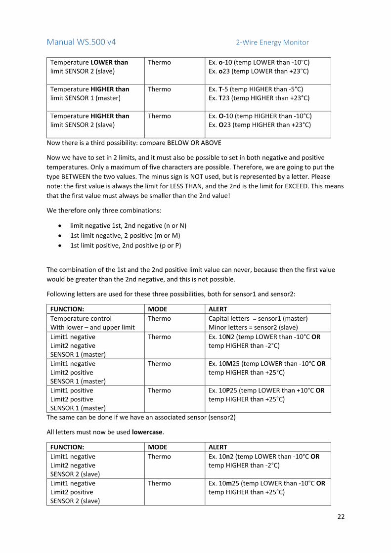
Temperature LOWER than limit SENSOR 1 (master)
Thermo Ex. t‐5 (temp LOWER than ‐5°C) Ex. t23 (temp LOWER than +23°C)
Manual WS.500 v4 2‐Wire Energy Monitor
22
Temperature LOWER than limit SENSOR 2 (slave)
Thermo Ex. o‐10 (temp LOWER than ‐10°C) Ex. o23 (temp LOWER than +23°C)
Temperature HIGHER than limit SENSOR 1 (master)
Thermo Ex. T‐5 (temp HIGHER than ‐5°C) Ex. T23 (temp HIGHER than +23°C)
Temperature HIGHER than limit SENSOR 2 (slave)
Thermo Ex. O‐10 (temp HIGHER than ‐10°C) Ex. O23 (temp HIGHER than +23°C)
Now there is a third possibility: compare BELOW OR ABOVE
Now we have to set in 2 limits, and it must also be possible to set in both negative and positive
temperatures. Only a maximum of five characters are possible. Therefore, we are going to put the
type BETWEEN the two values. The minus sign is NOT used, but is represented by a letter. Please
note: the first value is always the limit for LESS THAN, and the 2nd is the limit for EXCEED. This means
that the first value must always be smaller than the 2nd value!
We therefore only three combinations:
limit negative 1st, 2nd negative (n or N)
1st limit negative, 2 positive (m or M)
1st limit positive, 2nd positive (p or P)
The combination of the 1st and the 2nd positive limit value can never, because then the first value
would be greater than the 2nd negative, and this is not possible.
Following letters are used for these three possibilities, both for sensor1 and sensor2:
FUNCTION: MODE ALERT
Temperature control With lower – and upper limit
Thermo Capital letters = sensor1 (master) Minor letters = sensor2 (slave)
Limit1 negative Limit2 negative SENSOR 1 (master)
Thermo Ex. 10N2 (temp LOWER than ‐10°C OR temp HIGHER than ‐2°C)
Limit1 negative Limit2 positive SENSOR 1 (master)
Thermo Ex. 10M25 (temp LOWER than ‐10°C OR temp HIGHER than +25°C)
Limit1 positive Limit2 positive SENSOR 1 (master)
Thermo Ex. 10P25 (temp LOWER than +10°C OR temp HIGHER than +25°C)
The same can be done if we have an associated sensor (sensor2)
All letters must now be used lowercase.
FUNCTION: MODE ALERT
Limit1 negative Limit2 negative SENSOR 2 (slave)
Thermo Ex. 10n2 (temp LOWER than ‐10°C OR temp HIGHER than ‐2°C)
Limit1 negative Limit2 positive SENSOR 2 (slave)
Thermo Ex. 10m25 (temp LOWER than ‐10°C OR temp HIGHER than +25°C)

Manual WS.500 v4 2‐Wire Energy Monitor
23
Limit1 positive Limit2 positive SENSOR 2 (slave)
Thermo Ex. 10p25 (temp LOWER than +10°C OR temp HIGHER than +25°C)
An example of the warning:
A few more tips to make good use of these 'alerts':
To set up the limits of power monitoring or day consumption, you can look in the respective charts
during the week, and take the peak values.
Also look to the average on a weekly or monthly graph, and make your own conclusion: could I
achieve the same comfort with less energy? In what period are these tops in consumption? Too
many "sleep power" by devices in standby mode? Perhaps now you can see who is responsible for
the big waste. A little warning by your email alert tells you that there is (excessive?) too much
consumption, according to your configurations. Do you get constant alerts, adjust the limits, because
it may not start to work disturbing.
Good luck with this 'ALERTS'. This could be the start of your first 'savings' ...
11.LAYOUT Go to the menu CHANNELS. We now see the channel names in the same rank as those we have
created in our modules, but maybe this is not the order you like you see in the dashboard. It is also
interesting to 'group' the consumers.
Left there is a text field 'Group Name'. Furthermore, there are a number of buttons with the
following functions:
'NEW': Naming a group eg heating, lighting, ventilation, automatic head ...
"CHANGE": edit a group name

Manual WS.500 v4 2‐Wire Energy Monitor
24
'Delete': Remove group
"SORT" Order To determine the channels for the visualization
'DESCRIPTION': divide the channels into groups
"CANCEL": failure to implement the change
"SEND": forwarding groups to the web server
"DOWNLOAD": return showing previous configuration, provided that the changes were not
sent!
We must always begin with the completion of group names: Go to the field where "Group Name" is
stated and then enter a new group name in there. Press 'NEW'
The name will now appear in the "list box, press 'SEND' will turn red to
indicate that a change is happening, but we also get alert with the
message" RESET GROUPS? ", Press" Cancel "
So we will continue until all the groups have been given a name (max 8).
Now we can sort the channels if the order is not desired, press 'SORT'
Click on the channel text field that you want to move. This name is now coloured red. Then click on
the number field where you want the clicked channel to go to. The desired channel will now appear
in place and it is coloured yellow.
These two steps we repeat until all names in the desired order.

Manual WS.500 v4 2‐Wire Energy Monitor
25
Here is an example:
Now we have to divide the channels in the categories:
Press 'DESCRIPTION' and confirm the question "RESET GROUPS" ‐> OK
Now click on each time to the last channel of each group.
Each group is now coloured .... made mistake? No problem, you can always re‐order or delete / or
add new groups.
When everything is in order, then click "SEND".
example:

Manual WS.500 v4 2‐Wire Energy Monitor
26
12. MAIN CHANNELS AND ENERGY VALUE EPC Below the channels there are some specific channels that we can use for the overview of electricity
and heating consumption, water consumption and calculate the EPC level.
example:
When you have an overall measure of your electricity consumption (can also be a 'smart meters'
value), then enter the log‐channel number at the ELECTRA Ph1 field. This channel number will be
found in the table above (LOG_xx ). Do you have a three‐phase system, then you must enter the 3
channel numbers.
Ex. LOG_8 ‐ 9 and 10, the total measurements of phase 1‐phase 2 and stage 3
For the heating this can be gas or petroleum or electricity. If you measure these consumers on the
Web server, then also enter these channels. (The gas meter can also be linked via the smart meter
through the serial P1 connection at the EC.441)
Is there a pulse contact provided for the water meter (via EC.441 or PC.080), please fill out this
channel also.
And if you have solar panels and an energy meter (EMMxxx) connected to it, you can enter up to
three channels (for three‐phase meters)
Finally, we make an (approximate) calculation of the EPC level (energy efficiency value of the
building): This is a value in kWh / m2, which is in function of heat consumption and the area of the
house. The lower the number, the better your home is insulated.
The total consumption of heating is divided by the heated surfaces in the home. The unit is KWh /
m2. At the installation time we do not have logging values for the whole year the webserver then
makes an estimation of the missing time periods as a function of the heating period has already been
measured.
Manual WS.500 v4 2‐Wire Energy Monitor
27
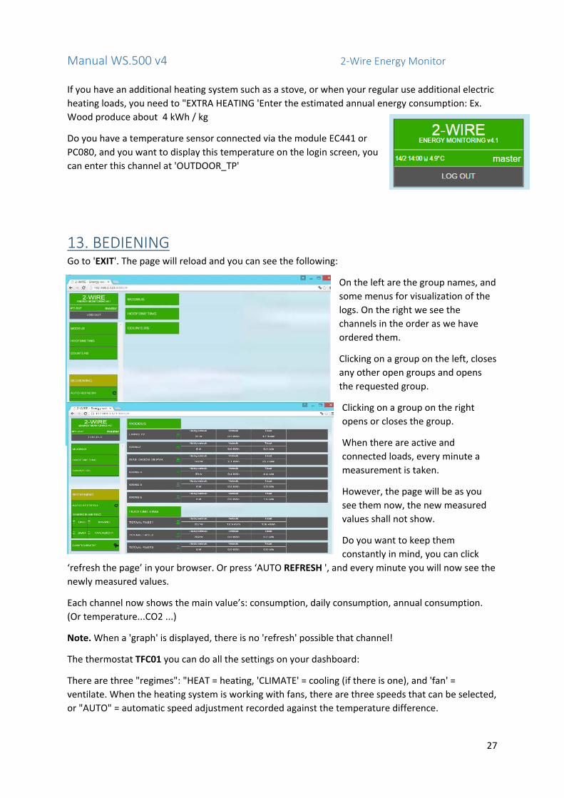
If you have an additional heating system such as a stove, or when your regular use additional electric
heating loads, you need to "EXTRA HEATING 'Enter the estimated annual energy consumption: Ex.
Wood produce about 4 kWh / kg
Do you have a temperature sensor connected via the module EC441 or
PC080, and you want to display this temperature on the login screen, you
can enter this channel at 'OUTDOOR_TP'
13. BEDIENING Go to 'EXIT'. The page will reload and you can see the following:
On the left are the group names, and
some menus for visualization of the
logs. On the right we see the
channels in the order as we have
ordered them.
Clicking on a group on the left, closes
any other open groups and opens
the requested group.
Clicking on a group on the right
opens or closes the group.
When there are active and
connected loads, every minute a
measurement is taken.
However, the page will be as you
see them now, the new measured
values shall not show.
Do you want to keep them
constantly in mind, you can click
‘refresh the page’ in your browser. Or press ‘AUTO REFRESH ', and every minute you will now see the
newly measured values.
Each channel now shows the main value’s: consumption, daily consumption, annual consumption.
(Or temperature...CO2 ...)
Note. When a 'graph' is displayed, there is no 'refresh' possible that channel!
The thermostat TFC01 you can do all the settings on your dashboard:
There are three "regimes": "HEAT = heating, 'CLIMATE' = cooling (if there is one), and 'fan' =
ventilate. When the heating system is working with fans, there are three speeds that can be selected,
or "AUTO" = automatic speed adjustment recorded against the temperature difference.

Manual WS.500 v4 2‐Wire Energy Monitor
28
At the right is the "set points to its left the" room temperature. " By pressing one of them (room
temperature) you can increase or decrease the set point by half a degree.
Below these temperatures, a red beam (= heat) or a blue beam (= air conditioning on) appears to
indicate present status.
ODERAT
In the AQM.CO2 module we see the room temperature, humidity, CO2 content, and an indication of the air quality (VOC): VERY GOOD ‐ GOOD ‐ MODERATE – POOR
14. GRAPHS CONTROL: Clicking on the name of a consumer in chart shows the daily consumption of that
consumer. To 'hover' over the chart we see a tooltip with the measurements in time.

Manual WS.500 v4 2‐Wire Energy Monitor
29
By clicking again on the name the month graph will be displayed
On the right there are two arrows <<< || >>> With these we can go back up to 7 days at the daily
schedule, or up to 12 months at the monthly statement. Click once more closes the chart.
Note. Opening a graphs for the first time may take several seconds (according to the speed of your
browser and laptop / tablet). The next time this will go considerably faster because the graphics are
buffered.
Clicking 'DAY' shows all channels simultaneously see their readings per hour.
Manual WS.500 v4 2‐Wire Energy Monitor
30
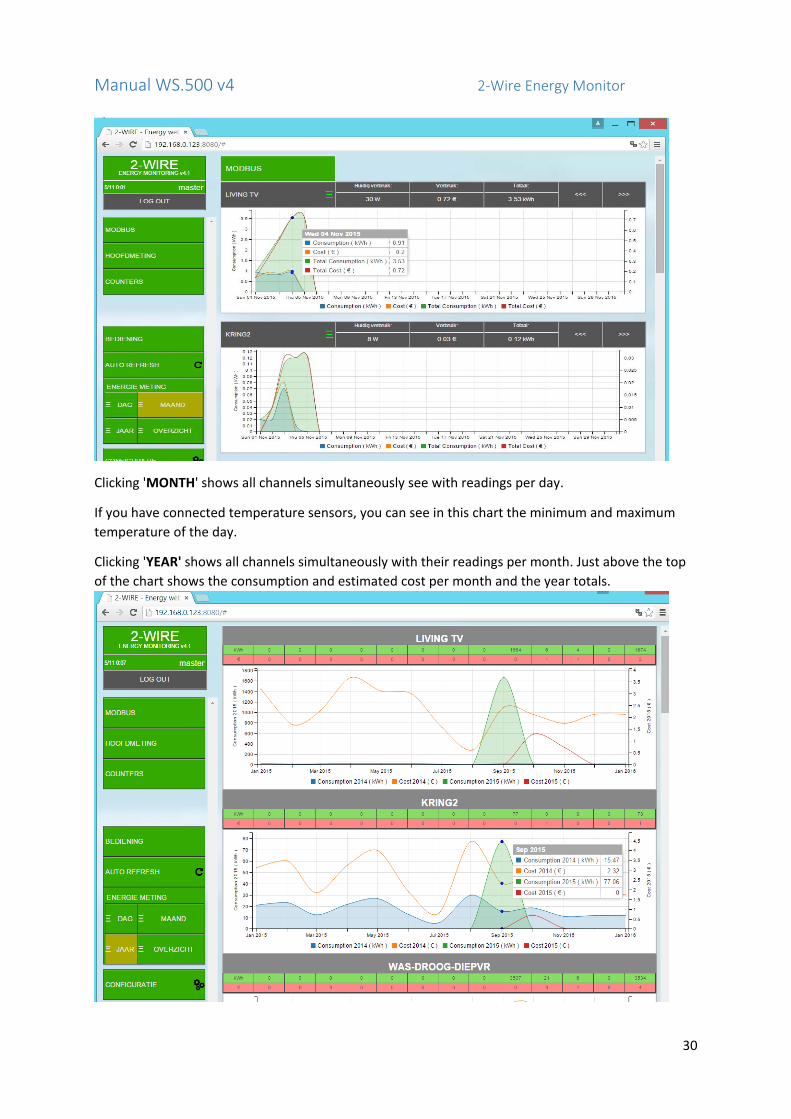
Clicking 'MONTH' shows all channels simultaneously see with readings per day.
If you have connected temperature sensors, you can see in this chart the minimum and maximum
temperature of the day.
Clicking 'YEAR' shows all channels simultaneously with their readings per month. Just above the top
of the chart shows the consumption and estimated cost per month and the year totals.

Manual WS.500 v4 2‐Wire Energy Monitor
31
Click on ‘OVERVIEW' shows in a table an overview of electricity consumption, heating consumption
(gas or oil), water and possibly yield of solar panels. An EPC (energy level) levels approximate
calculation is computed if the parameters are entered as explained in Chapter 11 (LAYOUT)
The "TOP 10 CONSUMERS 'gives an overview (in euros) of the most expensive energy consumers.
Below is a table reading a monthly consumption and projected energy costs. For comparison, you can
see the consumption of last year (if your system has been in service for over a year) The outputs are
sorted according to the largest costs.

Manual WS.500 v4 2‐Wire Energy Monitor
32
When you have filled in a canal at 'total electricity (see Chapter 12), then there's now see an extra channel:' VARIA ', this is the difference between the total measurement, and these measurements.
15. EXPORTING SUBTOTALS
It can be useful if you want to calculate consume over a given period, and there is even an (approximate) cost calculation.
To do this click on the menu on the left to "SUBTOTALS”. The following image now emerges.
Click the field next to "START DATE" and you will now see a calendar. Select the start date for the
period. Right on this calendar you can select the starting hour (per quarter).
Do the same for the end date (END DATE)
(Standard it is set to the current time)
Then click on the button "CALCULATE".
The screen will now show all the subtotals of the log channels. (Log channels CO2 or temperature are
not included in this table, only "consumers")
The waiting time for the calculation can vary in function of the period and the number of channels.
(Eg. Period 9 months, with 20 channels can last about 8 seconds)
An example:

Manual WS.500 v4 2‐Wire Energy Monitor
33
The table name first, then the consumption of the starting time (START VALUE), the consumption of
the end time (EndValue), the difference between the two (DIFF), the unit (UNITS) and the
(approximate) cost (COST) . This price was calculated according to the values entered in the
"SETTINGS".
In the 'Search' you can type part of a name and then these names are only shown which occur in the
keyword.
On top of the table, there are now several "buttons": this we can export the displayed table with the
filename = 'Subtotals ENERGY jaar_maand‐day‐hour‐minute, "and the extension:EXCEL: ‘.xlsx’
JSON: ‘.json’
CSV: ‘.csv’
PDF: ‘.pdf’
With the button “PRINT”‐ we can directly print out this table.
NB. Exports choices 'EXCEL' 'json' are not supported on many tablets (especially IPAD)
(Full support under Microsoft Windows)
16. LOGGING TOWARDS FTP‐SERVER Do you have your own FTP server? Or do you have one available through your service provider? Then
you can get more out of the 2‐WIRE Web server!
LOGGING:
LOG TYPES: The logs are in CSV format and separator is a “;”. The decimal separator is a “,”. There
are four types of logs available:
RT log: Real Time logs of measured values: voltage, current, power W (), power (VA), Power
Factor (PF), m3, m3 of gas, litres of fuel, temperature, CO2, ...
The interval can be set from 1 minute to 15 minutes. (NO is inactive) When active, the values
of all log‐modules are redirected to the log server following the interval.
You can specify which measurements are to be logged in the setting of each individual log‐
channel by a checkbox! (This occurs in the configuration of the modules)
File Name: LOCATION NAME + Log type + DATE + TIME + .csv
(Ex. Nieuwstraat18Aalst_RTLOG28082015_013003.csv)
RT Daylog (AMR): the webserver can also send all collected Real‐Time day‐logs once per
day. The interval of the measurements can be set here, from 1 minute to 60 minutes. In CSV
format we see all log channels with their associated measurements (as indicated in the
RTlog‐checkbox)
The CSV file has been prepared using the "AMR" format (see EANDIS)
Note: A file containing 32 log‐channels, each measuring about 5 types (V‐A‐W‐VA‐PF) with an

Manual WS.500 v4 2‐Wire Energy Monitor
34
interval of one minute takes approximately 1MB in size.
The point in time when the file is transmitted is set per hour.
The logging is starting from midnight to midnight.
File Name: LOCATION NAME + log type + DATE + TIME + .csv
(Ex. Nieuwstraat18Dendermonde_AMR_28082015_0001.csv)
Consumption log: The values can also be logged with intervals of 5 minutes to 60
minutes and will be forwarded directly to the log server. Here one can see the consumption,
split apart according to day and night rate. (if present)
If solar panels may also be displayed separately.
File Name: LOCATION NAME + Log type + DATE + TIME + .csv
(Ex. Nieuwstraat18Dendermonde_PAYLOG28082015_013003.csv)
Consumption Daylog (MMR): identically as in the RT Daylog, but only consumption,
with an adjustable interval of 5 to 60 minutes, or 1 total log of 24h.
The CSV file has been prepared using the "MMR" format (see EANDIS)
The point in time when the file is transmitted is set per hour.
The logging is starting from midnight to midnight.
File Name: LOCATION NAME + Log type + DATE + TIME + .csv
(Ex. Nieuwstraat18Dendermonde_MMR_28082015_013003.csv)
LOCATION NAME: This information is the file name, and also featured in the header of the file.
EANnr: can be invoice number, location number ...
17. DATA TRANSMISSION VIA HTTP
Log data retrieval is also available with a very simple HTTP request. Enter a statement in the 'Toolbar' from your browser and the 2‐WIRE Web server will answer with a mass of log data. When you can capture this data and process it in your database, you can create your own graphs, statistics or warnings at over‐consumption ....
The data has the 'JSON' format. The following commands are possible:
Retrieve current (real‐time) measurements (5logtypes) of all log‐channels
Retrieve historical (real‐time) measurements of the previous period (up to 3 years back)
Retrieve consumption‐by‐the‐hour Calling back hourly (up to 3 years back)
Daily consumption and daily energy cost (up to 1 years back)
Interested? Check our website and ask for the HTTP instruction‐set at www. 2‐WIRE.be
18. QUICK START A shortened repeat of all the steps:
5. Make the necessary connections of power, bus, LAN network.

Manual WS.500 v4 2‐Wire Energy Monitor
35
6. Retrieve the IP address and port number of your webserver via the “IP Server Scanner”
software.
7. Surf to the address and port number (default 8080)
8. Login with 'adminIP' or ‘admin2‐WIRE’ and password '2015'
9. Change to fix IP address: go back to menu "SETTINGS" (see Chapter 4)
10. Add new: go to menu "SETTINGS" old login = 'loginold' old pass = '1234'
11. Check energy prices: go to menu "SETTINGS", below, cost
12. Add new Modules: go to menu 'Modules' type serial number, assign names, parameters, fill
according to the type of module (see leaflet in this section) and send.
13. Create Channels: to menu CHANNELS ", first create groups (minimum 1), then sort channels,
divide the groups over the channels.
14. Main sources: if there are total measurements for menu CHANNELS 'type of channel
numbers for electricity, gas, water, heating oil.
15. Export of energy: if total measurements are for export (solar panels), to menu CHANNELS ",
typing in the channel number (s).
16. EPC‐level calculation: determine the heating source (s), to menu "CHANNELS", typing of this
log‐channel number (s) and estimated surface area of the heated rooms.
17. Go to 'EXIT' and test all channels. (Attention: logging appears only after the first hour!)
18. PROBLEM SOLUTIONS REFRESH PAGE: When you are on the website of your webserver, and the buttons give no reaction,
then you're probably lost the 'connection'. This may be because your login time has expired, or your
PC / tablet was turned off. If so, then go to the 'tool bar of your browser and refresh the page.
Usually you will have to log in again and then everything will work normally again.
When there are problems such as the message "page not found" or the 'hourglass' continues to run,
then there may be a network problem. Try to reload the page. If this is not successful, check whether
there is Internet connection by visiting a known website.
SEARCH IP‐ADRES: If you are unable to log in, and there's decent network connection, then you may
be using the wrong IP address. To determine this, we need an IP address scanner. This program can
be downloaded via the 2‐WIRE website. (IP Server Scanner). This program will make a 'broadcast' on
your local network to search for your Web server. When the server scanner has connection, you will
be able to read all settings. There may be assigned a different IP address. (DHCP ...) and this is the
way to find out.
NETWORK PROBLEM: If you cannot reach your web page even after checking with the Server
Scanner, please check the network cable: At the bottom of the web server where the network
connector is plugged in, there are two LEDs: green must still lit, the orange LED off and then light up
briefly.
When the orange LED never lights up, the network is not connected to your network.
On top of the WS500 close to the power connector there should light up a green LED, if so then the
power is okay. Right above there are two push‐buttons, with two associated LEDs. Both LEDs must be
off, and every 2 seconds the left side LED should light up briefly (heart beat).

Manual WS.500 v4 2‐Wire Energy Monitor
36
If there remains a continuous LED lights up, then something has gone wrong with the network. Turn
the power to the webserver and wait for 5 seconds, and turn back the power. The LED should light
up a 3 seconds and go out afterwards.
DHCP: When there are problems with DHCP (ex. your router has no IP address), and the Server
Scanner still cannot find a Web server, despite a decent network connection, you can decide to move
to a 'default' address:
Procedure: Power off the WS500, wait 5 seconds, push button 2 and hold, turn on power, and
continue to press until the LED starts to flash and keep on pressing another 3 seconds before release.
After about 5 seconds, all LEDs are off and the WS500 is at a fixed address. Now you need to
"browse" to the default IP address: 192.168.0.123:8080
Note: This address is not always suitable for the network where your PC or laptop is connected.
When you are in a different range, you must change the settings of your PC!
CHANGE IP‐ADRES: You can also change the IP address with the Server Scanner.
After the program has found your web server, you can manually change the current IP address with
this program. Type the address and port number, along with other data such SUBNET, GATEWAY,
DNS.
FAULTY JAVASCRIPT/STYLE: If you discover errors on the website, or there is no key that still reacts,
even after 'refresh page, then there may slipped an error when loading the script / style. You can
then manually re‐download the javascript by pressing the 2‐Wire Server button 1 (left, shortest at
the power connector) and keep pressing until the left LED lits continuously. Then release the key.
Now the LED 15 to 20 seconds should stay on and then go out again. If this is OK, then you do the
right button (press 2) just the same: keep pressing until the flashing stops and both LEDs light up
continuously, then release the key.
Now the LEDs must also be 15 to 20 seconds on and then the right LED starts quickly flashing.
Afterwards the LED will burn continuously 3 seconds and then go out. Everything fine !!!
When these things happen as described, then try again "refresh page and sign in.
CLEAR COMPLETE DATABASE, RESET IP and PASSWORD:
Key 1 (shortest to power connector)
Procedure: Power off the WS500, wait 5 seconds, press button 1 and hold, turn on power, and
continue to press until the LED starts flashing, keep pushing another 3seconds until the LED stops
blinking and then release.
The delete process may take about 60 seconds, and the WS500 is ready when the LED goes out.
IFORGOT IP‐ADRES or FORGOT PASSWORD:
Key 2 (far right away from the connector)
Procedure: Power off the WS500, wait 5 seconds, push button 2 and hold, turn on power, and
continue to press until the LED starts to flash. Stay on pushing another 3 seconds until the LED stops
blinking and then release.

Manual WS.500 v4 2‐Wire Energy Monitor
37
The delete process can take about 3 seconds, and the WS500 is ready when the LED goes out.
Now you need to "browse" to the default IP address: 192.168.0.123:8080 and login, password as
described in Part 8
In summary:
Pressing buttons during the running:
Key 1: Upgrading Javascript and CSS.
Key 2: Upgrading firmware Webserver WS500
Pressing keys during startup POWER:
Key 1: Delete entire database, IP address, reset, login and password
Key 2: reset the IP address and password.
2‐WIRE 2015


![á F] - vaillant.pl · 3e DHW 10c 5 2 12d 3 12d 3c 10c 3 12d 12 12a 9j 8e 9h BUS BUS BUS BUS BUS BUS BUS BUS BUS BUS BUS 8c 8f BUS 12d (S9) 8b 3f2 10c 9a FS2 12k2 9c 2 4 33 9k2 12d](https://img.pdfslide.us/doc/110x75/5c69bd9909d3f21a048b9235/a-f-3e-dhw-10c-5-2-12d-3-12d-3c-10c-3-12d-12-12a-9j-8e-9h-bus-bus-bus-bus.jpg)


![BUS BUS BUS BUS BUS BUS BUS BUS BUS · Sunday 15 May 2016 Liverpool Street to Colchester, Ipswich, Norwich and branches BUS BUS BUS BUS BUS BUS BUS BUS BUS] 1 1 1 1 1 1 1 1 1 1 1](https://img.pdfslide.us/doc/110x75/5fab4ce2477d2d3adf21016a/bus-bus-bus-bus-bus-bus-bus-bus-sunday-15-may-2016-liverpool-street-to-colchester.jpg)