Embed Size (px)
Citation preview

Practice Section 1672 Issue 6, September 2014
2O3D3-19A REVB MOUNTING
Multiple Patents Pending
CLEI™ Code SOM2300C, CPR 204577
Trademarks used in this manual: CLEI is a trademark of Telcordia Technologies, Inc. dba iconective. ETL Listed is a registered certification mark of Intertek Testing Services NA, Incorporated. GMT is a trademark of Bussmann Corp. Pulsecom is a registered trademark of Hubbell Incorporated. 200 Mechanics is a registered trademark of Westell Technologies, Incorporated. ©2014 Pulse Communications, Inc. All rights reserved.
1
ETL LISTED CONFORMS TO UL STD 60950-1
CONTENTS PAGE
1 INTRODUCTION ........................................................................................................................ 2 1.1 Reason for Reissue ............................................................................................................ 2 1.2 Description .......................................................................................................................... 2 1.3 Features ............................................................................................................................. 2
2 INSTALLATION ......................................................................................................................... 4 3 SPECIFICATIONS ................................................................................................................... 17 4 MAINTENANCE ....................................................................................................................... 17 5 CUSTOMER SERVICE ............................................................................................................ 18
Figure 1: 2O3D3-19A REVB Mounting

2O3D3-19A REVB 1672, Issue 6, September 2014
2
1 INTRODUCTION
This practice describes the Pulsecom® 2O3D3-19A REVB Mounting, shown in Figure 1. The 2O3D3-19A REVB accepts a variety of Pulsecom all-in-one modules as well as other Type 400 or 200 Mechanics® cards. Installation instructions and engineering references are included.
1.1 Reason for Reissue
This practice has been reissued to add information on the O3-3D3DN unit.
1.2 Description
The 2O3D3-19A REVB mounts in a 19" or 23" rack or can be attached to a wall. The O3D3-19A REVB can be used to house the following units:
• O3D3-MO units that derive a DS3 circuit from an OC3 optical facility
• O3-3D3DN units that derive three DS3 circuits from an OC3 optical facility
• O3-4D1B units that derive four DS1 signals from an OC3 optical facility
• O3-12D1D units that derive twelve DS1 signals from an OC3 optical facility
• O3-12D1DN units that derive twelve DS1 signals from an OC3 optical facility and include enhanced Network Monitoring and Administration (NMA) access capabilities
• O3-12D1G units that support four 1Gb Ethernet and twelve DS1 signals from an optical facility
• PCAU Series units that derive a high-fidelity audio circuit from a data link transported over a twisted pair to a standard two binary one quaternary (2B1Q) U-Interface line card
1.3 Features
The mounting provides the following features:
• Operation up to 75°C (167°F)
• 400 Mechanics to provide inexpensive installation in central office (CO), digital loop carrier (DLC) remote terminal (RT), or customer-premises equipment (CPE) applications
• 19" or 23" rack-mounting as well as wall-mounting flexibility
• Individual fuses per card slot
• Redundant A/B inputs of the same voltage via diode isolation
• 24 VDC and 48 VDC operation
• Unique cable tunnel that permits rear cables to be routed to the front in DLC RT applications or front cables to be routed to the rear for maximum installation flexibility
• Card slots that are fully independent and separately fused to support any mixture of services

2O3D3-19A REVB 1672, Issue 6, September 2014
3
• Designed to accommodate Ethernet and time-division multiplexing (TDM) cell site, digital subscriber line (DSL), and business services
• Front access to fiber, coaxial cables, and fuses
• Rear access to power, frame ground, and alarm screw terminal block cables that can be routed to the front via the cable tunnel
• Integral fiber management
• Integral thermal management that permits the 2O3D3-19A REVB to be located in elevated temperature areas such as RT cabinets or Tempest cabinets for installations at broadcast transmission sites
• Ground stud that accommodates up to a #6 ground wire
• Electrostatic discharge (ESD) ground strap receptacle

2O3D3-19A REVB 1672, Issue 6, September 2014
4
2 INSTALLATION
Overview
Per GR-1089-CORE June 2006, Section 9.8, battery return (BR) of the 2O3D3-19A REVB does not have any internal connection to the frame and, therefore, may be used in either DC-C (common bonding and grounding systems) or DC-I (isolated bonding and grounding systems). The chassis ground wire must be at least as large as the wire used for the BR.
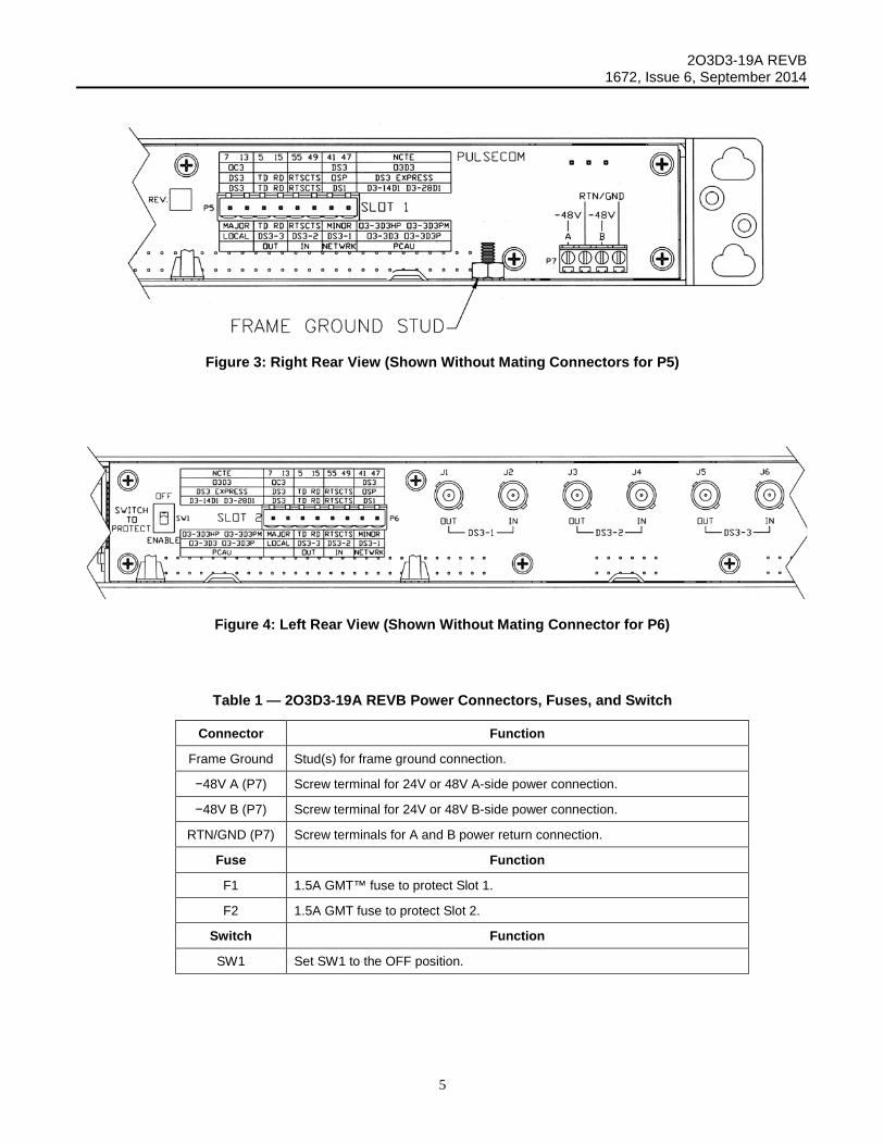
Figure 2, Figure 3, and Figure 4 illustrate rear views of the 2O3D3-19A REVB. Figure 5, Figure 6, and Figure 7 show front, top, and side views, respectively. Table 1, Table 2, and Table 3 describe the connectors, fuses, and switch shown in these figures.
Mount in Rack or on Wall
Rack—For horizontal mounting, install the 2O3D3-19A REVB in a 19" or 23" rack as described in Procedure 1. Optional demarc mounting panels and “CPM” Series jack/cable kits are available as listed in Table 4; also refer to Figure 8 and Figure 9. If desired, follow the steps in Procedure 2 to install an optional 2O3D3-19-HORIZ on a 23" rack; see Figure 10 and Figure 11. For vertical mounting with an optional 2O3D3-19-VERT, install the 2O3D3-19A REVB as shown in Procedure 3 and Figure 12.
Wall—Figure 13 and Figure 14 show the 2O3D3-19A REVB with its mounting ears configured for wall or backboard mounting. Install the 2O3D3-19A REVB as described in Procedure 4.
Make Power, Ground, and Alarm/Signal Connections
Follow the steps in Procedure 5 if connecting −48 VDC power. Follow Procedure 6 if connecting a +24 VDC or −24 VDC power supply.
Figure 2: Rear View (Shown Without Mating Connectors for P5 and P6)
WARNING
This mounting includes components that are susceptible to damage from static electricity. DO NOT handle without protection from electrostatic discharge.
2O3D3-19A REVB 1672, Issue 6, September 2014
5
Table 1 — 2O3D3-19A REVB Power Connectors, Fuses, and Switch
Connector Function
Frame Ground Stud(s) for frame ground connection.
−48V A (P7) Screw terminal for 24V or 48V A-side power connection.
−48V B (P7) Screw terminal for 24V or 48V B-side power connection.
RTN/GND (P7) Screw terminals for A and B power return connection.
Fuse Function
F1 1.5A GMT™ fuse to protect Slot 1.
F2 1.5A GMT fuse to protect Slot 2.
Switch Function
SW1 Set SW1 to the OFF position.
Figure 3: Right Rear View (Shown Without Mating Connectors for P5)
Figure 4: Left Rear View (Shown Without Mating Connector for P6)

2O3D3-19A REVB 1672, Issue 6, September 2014
6
Table 2 — Shelf Backplane J1 Through J6 Connector Functions
Connector Silkscreen Label Function
J1 DS3-1 OUT
75-ohm BNC connectors not used
J2 DS3-1 IN
J3 DS3-2 OUT
J4 DS3-2 IN
J5 DS3-3 OUT
J6 DS3-3 IN
Table 3 — Shelf Backplane P5 (Slot 1) and P6 (Slot 2) Connector Functions
Plug-In Module Family
Silkscreen
Label
Function
O3-4D1B
O3-12D1D
O3-12D1DN
7 13 OC3 alarm terminals
5 15 Not used
55 49 Not used
41 47 DS1 alarm terminals
O3-12D1G 7 13 Alarm indication signal (AIS) or remote alarm indication (RAI) on enabled DS1, unit failure
5 15 Not used
55 49 Not used
41 47 Loss of frame (LOF) or loss of signal (LOS) on enabled DS1, unit failure
O3D3-MO
O3-3D3DN
OC3 OC3 alarm terminals
– Not used
– Not used
DS3 DS3 alarm terminals
PCAU – Not used
OUT 600-ohm audio output
IN 600-ohm audio input
NETWRK 2B1Q network connection
NOTE: 18–22 AWG is the recommended wire range for all P5 and P6 connections.

2O3D3-19A REVB 1672, Issue 6, September 2014
7
Table 4 — Optional Panels and Kits for Rack Mounting
Procedure 1. Mounting the 2O3D3-19A REVB in a Rack
STEP ACTION
1 Pulsecom supplies four #12–24 × 1/2" screws for installing the mounting in racks with corresponding holes. Otherwise, the installer will need to supply four binder-head screws of the appropriate size to fit the equipment rack mounting holes. Refer to Figure 5, Figure 6, and Figure 7.
2 The 2O3D3-19A REVB is equipped with reversible mounting ears for placement in either 19" or 23" racks. The unit is shipped with the ears in the 19" position. If necessary, remove the ears and reverse them for the 23" position.
3 Hold the equipment in the equipment rack in the desired position.
NOTE: In 19" racks, it is required that 1" above and below the mounting be left unused for heat dissipation.
4 Line up any two holes in the shelf with holes in the equipment rack.
5 Insert the screws through the shelf mounting holes and into the equipment rack holes.
6 Tighten the screws.
7 To mount an optional BP-19 or BP-23 panel (if desired), repeat Steps 3–6 using installer-supplied screws. The panel should be installed at least 1" above the 2O3D3-19A REVB to leave room for cables. Use the cables supplied with the appropriate CPM Series kit listed in Table 4; also see Figure 8 and Figure 9.
Figure 5: Rack-Mount – Front View
Ordering Code Description
BP-19 One demarc mounting panel for 19" racks (three demarc kit capacity*)
BP-23 One demarc mounting panel for 23" racks (four demarc kit capacity*)
CPM-4DS1X Demarc kit for four DS1 ports, RJ48C connector (O3-4D1B units)
CPM-12DS1X Demarc kit for twelve DS1 ports, RJ48C connector (O3-12D1D and O3-12D1DN units)
CPM-SG-12DS1X Demarc kit for twelve DS1 ports, RJ48C connector (O3-12D1G units)
CPM-DS3 Demarc kit for one DS3 port, BNC connector (O3D3-MO and O3-3D3DN units)
*Kits must be ordered separately.

2O3D3-19A REVB 1672, Issue 6, September 2014
8
Figure 6: Rack-Mount – Top View
Figure 7: Rack-Mount – Side View

2O3D3-19A REVB 1672, Issue 6, September 2014
9
Figure 8: Rack-Mount View With Optional BP-19 Installed (Shown With Typical Demarc Jacks but Without Cables)

2O3D3-19A REVB 1672, Issue 6, September 2014
10
Figure 9: Rack-Mount View With Optional BP-23 Installed (Shown With Typical Demarc Jacks but Without Cables)
Procedure 2. Mounting the Optional 2O3D3-19-HORIZ
STEP ACTION
1 Hold the 2O3D3-19-HORIZ below and parallel to the 2O3D3-19A REVB in the equipment rack. See Figure 10 and Figure 11.
2 Line up the holes in the 2O3D3-19-HORIZ mounting ears with the holes in the rack, leaving one rack unit gap between the 2O3D3-19A REVB and the 2O3D3-19-HORIZ.
3 Using the four screws, flat washers, and lock washers supplied with the 2O3D3-19-HORIZ, secure the 2O3D3-19-HORIZ to the rack.

2O3D3-19A REVB 1672, Issue 6, September 2014
11
Figure 10: 2O3D3-19-HORIZ – Side View
Figure 11: 2O3D3-19-HORIZ – Front View

2O3D3-19A REVB 1672, Issue 6, September 2014
12
Procedure 3. Mounting the 2O3D3-19A REVB to a 2O3D3-19-VERT
STEP ACTION
1 Using the eight screws, flat washers, and lock washers supplied with the 2O3D3-19-VERT, install the VERT brackets with a space of 17.5 inches between the inside edges of the two brackets. See Figure 12.
2 Obtain four #12-24 machine screws (supplied with the 2O3D3-19A REVB) for mounting the shelf to the 2O3D3-19-VERT.
3 Hold the 2O3D3-19A REVB vertically against the VERT brackets in the desired position.
NOTE: Be sure that the device is positioned so that the fuses are at the bottom.
4 Line up the two holes in the upper 2O3D3-19A REVB mounting ears with any two holes in the upper VERT bracket.
5 Insert the screws through the mounting ears and into the upper VERT bracket holes. Tighten the screws.
6 Repeat Steps 4 and 5 for the lower VERT bracket.
Figure 12: Rack-Mount View With Optional 2OD3D-19-VERT Installed
17.5

2O3D3-19A REVB 1672, Issue 6, September 2014
13
Procedure 4. Mounting the 2O3D3-19A REVB on a Wall
STEP ACTION
1 Select a position near a suitable power source. The Pulsecom 2100-0300 AC wall transformer or the POWER NODE/6 heavy-duty power system with 8 hours of battery reserve can be used.
2 Remove the mounting ears and reattach them in the wall-mounting position as shown in Figure 13. The ears are positioned to hold the shelf away from the wall for optimum cooling.
3 Obtain suitable #12 hardware for mounting to a backboard or, if required, directly to a wall.
4 Hold the mounting in the desired position on the wall. See Figure 14.
NOTE: Be sure that the device is positioned so that the fuses are at the bottom.
5 Use a pencil to mark the mounting hole positions. Then drill appropriately sized holes for the mounting hardware to be used.
WARNING: Avoid hitting pipes or wires in the wall when drilling.
6 Insert screws through the shelf mounting holes and into the backboard or, if used, wall anchors.
7 Tighten the screws.
Figure 13: 2O3D3-19A REVB Wall Mounting – Bracket Orientation

2O3D3-19A REVB 1672, Issue 6, September 2014
14
Figure 14: 2O3D3-19A REVB Wall Mounting – Shelf Orientation

2O3D3-19A REVB 1672, Issue 6, September 2014
15
Procedure 5. Making −48V Power, Ground, and Alarm/Signal Connections
STEP ACTION
1 Ensure that 2O3D3-19A REVB 1.5A fuses (supplied) are installed in faceplate F1 and F2 fuse holders and that power is not applied to the wires that will be used to connect power to the mounting. (A pair of 0.75A fuses is also included with the 2O3D3-19A REVB.)
2 Connect frame ground to the frame ground stud using 6 AWG wire. See Figure 3.
3 Locate the small screwdriver supplied with the mounting to assist in making the connections in Steps 4 through 8.
4 Disconnect power at the source and connect –48 VDC A Supply Return to the P7 RTN/GND terminal using 22 AWG minimum to 14 AWG maximum wire. (Appropriate wire size depends upon length of run.)
5 Connect –48 VDC A Power Source to the P7 –48V A terminal using 22 AWG minimum to 14 AWG maximum wire. (Appropriate wire size depends upon length of run; use heavier gauge for longer runs.)
6 NOTE: If used, the redundant supply must be the same voltage as the primary supply.
If desired, connect the optional −48 VDC B Supply Return to the P7 RTN/GND terminal using 22 AWG minimum to 14 AWG maximum wire and connect the optional −48 DC B Power Source to the P7 −48 V B terminal using 22 AWG minimum to 14 AWG maximum wire. (Appropriate wire size depends upon length of run.)
7 Install a 3A fuse or larger at the source for the A supply leads and, if used, another 3A fuse for the B supply leads.
8 If desired for Slot 1 and Slot 2, wire alarm or signal leads in accordance with Table 2, Table 3, and Figure 4.
9 On the 2O3D3-19A REVB backplane, verify that switch SW1 is set to the OFF position.
10 WARNING: When connecting fibers, use care to avoid breaking them. Always follow fiber bend radius guidelines. Use the center plastic clip only for fiber cables.
CAUTION: To prevent accidental disconnection, adequately secure all wiring connections and provide strain relief.
Plug in the modules and connect the coax and fiber cables as required. Use the supplied tie-wraps/cable clamps to secure these cables.
11 Bond all cable shields securely to the chassis using the provided studs.
12 Apply power.

2O3D3-19A REVB 1672, Issue 6, September 2014
16
Procedure 6. Making +24V or −24V Power, Ground, and Alarm/Signal Connections
STEP ACTION
1 Ensure that the 24 VDC source can support the power requirements of the plug-in units that will be installed.*
2 Ensure that 2O3D3-19A REVB 1.5A fuses (supplied) are installed in faceplate F1 and F2 fuse holders and that power is not applied to the wires that will be used to connect power to the mounting.
3 Connect frame ground to the frame ground stud using 6 AWG wire. See Figure 3.
4 Locate the small screwdriver supplied with the mounting to assist in making the connections in Steps 5 through 9.
5 Disconnect the power at the source and connect the positive side of the 24V source to the P7 A-side RTN/GND terminal using 22 AWG minimum to 14 AWG maximum wire. (Appropriate wire size depends upon length of run; use heavier gauge for longer runs.)
6 Connect the negative side of the 24V source to the P7 “−48V A” terminal using 22 AWG minimum to 14 AWG maximum wire. (Appropriate wire size depends upon length of run; use heavier gauge for longer runs.)
7 NOTE: The redundant supply must be the same voltage as the primary supply. Redundant positive-referenced supplies (+24V) cannot be used.
If a redundant input power supply is desired, connect the positive side of the second 24V source to the P7 B-side RTN/GND terminal. Then connect the negative side of the redundant 24V source to the P7 “–48V B” terminal. Use 22 AWG minimum to 14 AWG maximum wire, as appropriate.
8 Install a 3A fuse or larger at the source for the A supply leads and, if used, another 3A fuse or larger for the B supply leads.
9 If desired for Slot 1 and Slot 2, wire alarm or signal leads in accordance with Table 2, Table 3, and Figure 4.
10 On the 2O3D3-19A REVB backplane, verify that switch SW1 is set to the OFF position.
11 WARNING: When connecting fibers, use care to avoid breaking them. Always follow fiber bend radius guidelines. Use the center plastic clip only for fiber cables.
CAUTION: To prevent accidental disconnection, adequately secure all wiring connections and provide strain relief.
Plug in the modules and connect the coax and fiber cables as required. Use the supplied tie-wraps/cable clamps to secure these cables.
12 Bond all cable shields securely to the chassis using the provided studs.
13 Apply power.
*The PCAU Family requires –48 VDC power.

2O3D3-19A REVB 1672, Issue 6, September 2014
17
3 SPECIFICATIONS
Table 5 lists the electrical and physical characteristics of the mounting.
Table 5 — 2O3D3-19A REVB Specifications
Description Specification
A. Power Requirement
Input Voltage Range 21 to 56.7 VDC
Maximum Input Current
a) At –48V
b) At +24V or −24V
0.8 A
1.6 A
Fan Power 4.5 Watts
B. Environmental
Temperature Range, Operating and Storage −40° to +75°C (−40° to +167°F)
Relative Humidity, No Condensation 10% minimum to 95% maximum
Size (height x width x depth) 1.75 x 23 x 11 inches (4.4 x 58.4 x 27.9 cm)
Weight, Approximate 3 pounds (1.4 Kg)
C. Fan Operation
Fan On 40°C ± 5°C (104°F ± 9°F)
Fan Off, Minimum 20°C ± 1°C (68°F ± 2°F)
4 MAINTENANCE
No routine maintenance is required.
Three spare fuses are supplied with the mounting: one 1.5A and two 0.75A. Table 6 lists ordering codes for replacement parts.
Table 6 — Replacement Parts
Description Pulsecom Part Number
0.75A GMT Fuse 003337-0075
1.5A GMT Fuse 003337-0150
Fan Assembly 2O3D3-19AFAN
NOTE: The fan assembly can be replaced while the shelf is in operation.

2O3D3-19A REVB 1672, Issue 6, September 2014
18
5 CUSTOMER SERVICE
Direct any questions concerning the operation of the mounting to Pulsecom Technical Support. Obtain repair services by returning the defective mounting to the Pulsecom Repair Department, 400 E. Wyomissing Avenue, Mohnton, PA 19540; email [email protected].
Pulse Communications, Inc. Customer Service
2900 Towerview Road, Suite 200 1-800-381-1997
Herndon, Virginia 20171 [email protected]
400 E. Wyomissing Avenue Technical Support
Mohnton, Pennsylvania 19540 1-800-841-1005
PRINTED IN USA [email protected]