Embed Size (px)
Citation preview
COMPRESSOR & GAS TURBINE WORKSHOP GAS TURBINES - Slide 1
GAS TURBINES & Centrifugal Compressor
Prepared & Presented by
Nauman Hannani
November 2012
COMPRESSOR & GAS TURBINE WORKSHOP GAS TURBINES - Slide 2
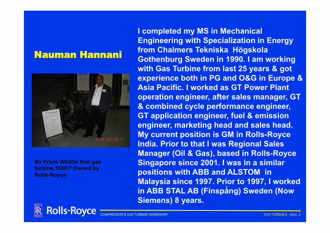
Nauman Hannani
I completed my MS in Mechanical Engineering with Specialization in Energy from Chalmers Tekniska Högskola Gothenburg Sweden in 1990. I am working with Gas Turbine from last 25 years & got experience both in PG and O&G in Europe & Asia Pacific. I worked as GT Power Plant operation engineer, after sales manager, GT & combined cycle performance engineer, GT application engineer, fuel & emission engineer, marketing head and sales head. My current position is GM in Rolls-Royce India. Prior to that I was Regional Sales Manager (Oil & Gas), based in Rolls-Royce Singapore since 2001. I was in a similar positions with ABB and ALSTOM in Malaysia since 1997. Prior to 1997, I worked in ABB STAL AB (Finspǻng) Sweden (Now Siemens) 8 years.
Sir Frank Whittle first gas turbine,1930/7 Owned by Rolls-Royce
COMPRESSOR & GAS TURBINE WORKSHOP GAS TURBINES - Slide 3
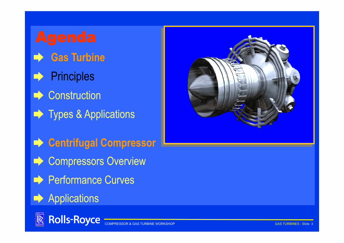
Agenda ➨ Gas Turbine ➨ Principles ➨ Construction ➨ Types & Applications
➨ Centrifugal Compressor ➨ Compressors Overview ➨ Performance Curves ➨ Applications
•
COMPRESSOR & GAS TURBINE WORKSHOP GAS TURBINES - Slide 4 main menu
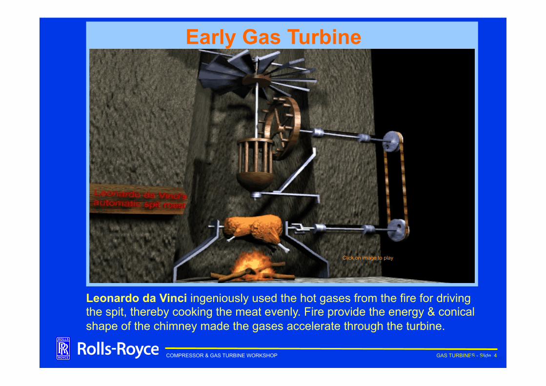
Early Gas Turbine
Click on image to play
Leonardo da Vinci ingeniously used the hot gases from the fire for driving the spit, thereby cooking the meat evenly. Fire provide the energy & conical shape of the chimney made the gases accelerate through the turbine.
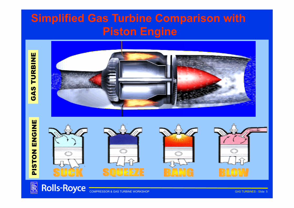
COMPRESSOR & GAS TURBINE WORKSHOP GAS TURBINES - Slide 5
Simplified Gas Turbine Comparison with Piston Engine
PIS
TO
N E
NG
INE
GA
S T
UR
BIN
E
COMPRESSOR & GAS TURBINE WORKSHOP GAS TURBINES - Slide 6
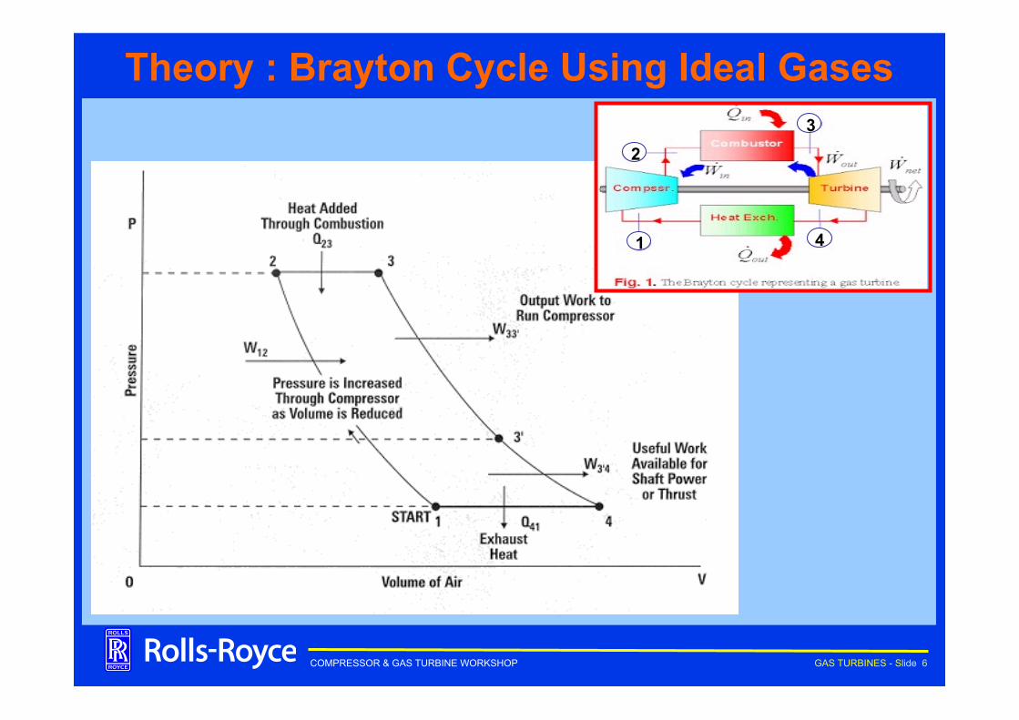
Theory : Brayton Cycle Using Ideal Gases
2
4
3
1
COMPRESSOR & GAS TURBINE WORKSHOP GAS TURBINES - Slide 7
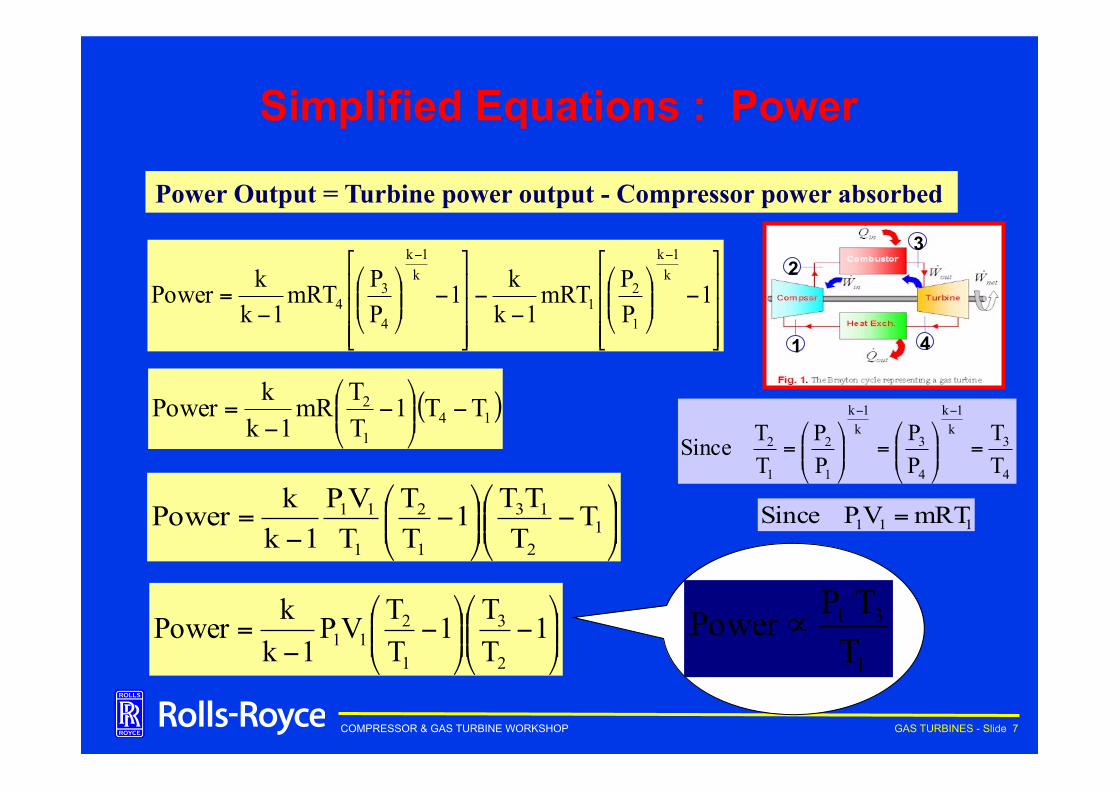
Simplified Equations : Power
Power Output = Turbine power output - Compressor power absorbed
⎥⎥⎥
⎦
⎤
⎢⎢⎢
⎣
⎡−⎟⎟
⎠
⎞⎜⎜⎝
⎛
−−
⎥⎥⎥
⎦
⎤
⎢⎢⎢
⎣
⎡−⎟⎟
⎠
⎞⎜⎜⎝
⎛
−=
−−
1PPmRT
1kk1
PPmRT
1kkPower
k1k
1
21
k1k
4
34
( )141
2 TT1TTmR
1kkPower −⎟⎟
⎠
⎞⎜⎜⎝
⎛−
−=
4
3k1k
4
3k1k
1
2
1
2
TT
PP
PP
TTSince =⎟⎟
⎠
⎞⎜⎜⎝
⎛=⎟⎟
⎠
⎞⎜⎜⎝
⎛=
−−
⎟⎟⎠
⎞⎜⎜⎝
⎛−⎟⎟
⎠
⎞⎜⎜⎝
⎛−
−= 1
2
13
1
2
1
11 TTTT1
TT
TVP
1kkPower 111 mRTVPSince =
⎟⎟⎠
⎞⎜⎜⎝
⎛−⎟⎟
⎠
⎞⎜⎜⎝
⎛−
−= 1
TT1
TTVP
1kkPower
2
3
1
211
1
31
TTPPower ∝
2
4
3
1
COMPRESSOR & GAS TURBINE WORKSHOP GAS TURBINES - Slide 8
Simplified Equations : Efficiency
InputHeatOutputPowerEfficiency =
⎟⎟⎠
⎞⎜⎜⎝
⎛−⎟⎟
⎠
⎞⎜⎜⎝
⎛−
−= 1
2
13
1
2 TTTT1
TTmR
1kkPower
1
2
1
2
PP
TTEfficiency ∝∝
( )23p TTmCInputHeat −=
( )
( )23p
232
1
1
2
TTmC
TTTT1
TTmR
1kk
Efficiency−
−⎟⎟⎠
⎞⎜⎜⎝
⎛−
−=
⎟⎟⎠
⎞⎜⎜⎝
⎛−
−=
2
1
p TT1
CR
1kkEfficiency
⎟⎟⎠
⎞⎜⎜⎝
⎛−∝
2
11TTEfficiency
2
4
3
1
COMPRESSOR & GAS TURBINE WORKSHOP GAS TURBINES - Slide 9
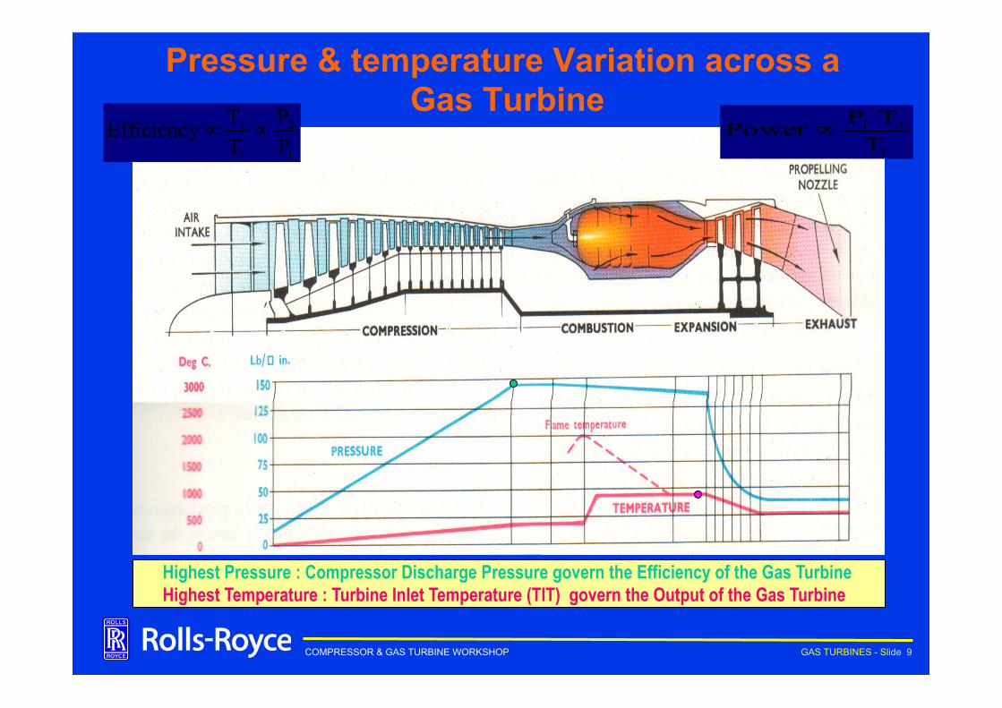
Pressure & temperature Variation across a Gas Turbine
Highest Pressure : Compressor Discharge Pressure govern the Efficiency of the Gas Turbine Highest Temperature : Turbine Inlet Temperature (TIT) govern the Output of the Gas Turbine
1
31
TTPPower ∝
1
2
1
2
PP
TTEfficiency ∝∝
COMPRESSOR & GAS TURBINE WORKSHOP GAS TURBINES - Slide 10
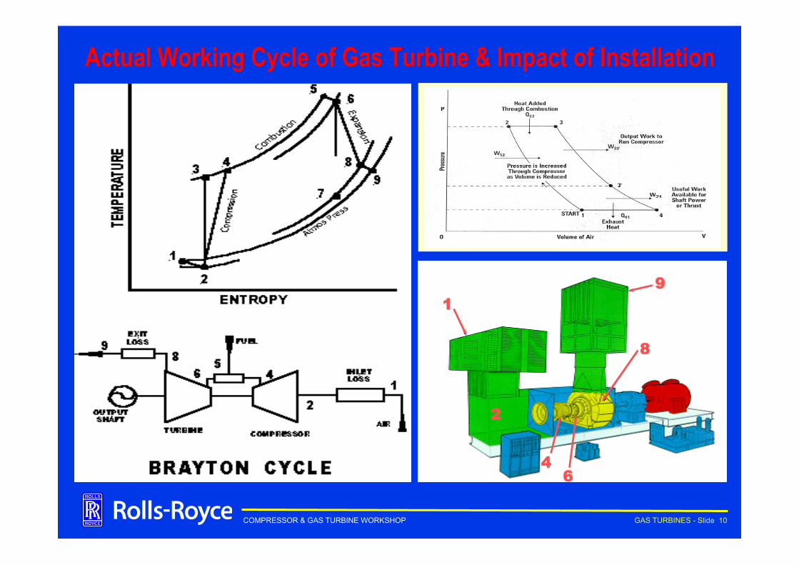
Actual Working Cycle of Gas Turbine & Impact of Installation
1
8
6 4
2
9
COMPRESSOR & GAS TURBINE WORKSHOP GAS TURBINES - Slide 11
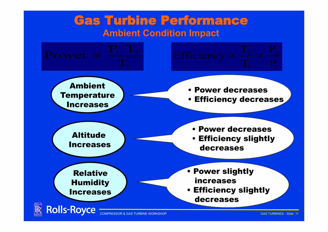
Gas Turbine Performance Ambient Condition Impact
1
2
1
2
PP
TTEfficiency ∝∝
1
31
TTPPower ∝
Ö Power increase with increase in TIT Ö Power decreases with elevation Ö Power increases with Ambient Temp. Ö Power decreases with Inlet losses Ö Efficiency increases with increase in TIT Ö Efficiency decreases with Ambient Temp.
• Power decreases • Efficiency decreases
Ambient Temperature
Increases
Altitude Increases
• Power decreases • Efficiency slightly decreases
Relative Humidity Increases
• Power slightly increases • Efficiency slightly decreases
COMPRESSOR & GAS TURBINE WORKSHOP GAS TURBINES - Slide 12
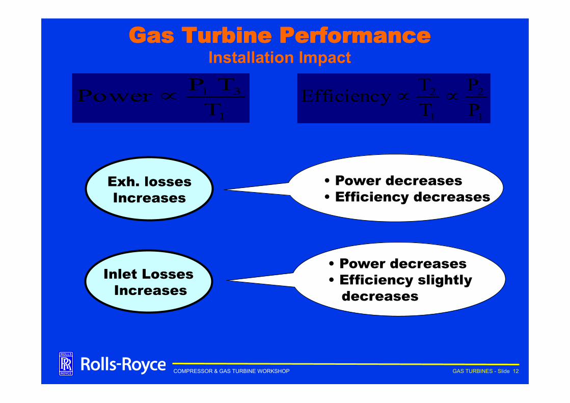
Gas Turbine Performance Installation Impact
1
2
1
2
PP
TTEfficiency ∝∝
1
31
TTPPower ∝
Ö Power increase with increase in TIT Ö Power decreases with elevation Ö Power increases with Ambient Temp. Ö Power decreases with Inlet losses Ö Efficiency increases with increase in TIT Ö Efficiency decreases with Ambient Temp.
• Power decreases • Efficiency decreases
Exh. losses Increases
Inlet Losses Increases
• Power decreases • Efficiency slightly decreases
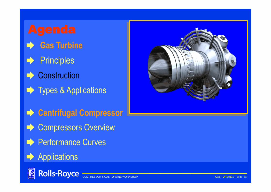
COMPRESSOR & GAS TURBINE WORKSHOP GAS TURBINES - Slide 13
Agenda ➨ Gas Turbine ➨ Principles ➨ Construction ➨ Types & Applications
➨ Centrifugal Compressor ➨ Compressors Overview ➨ Performance Curves ➨ Applications
•
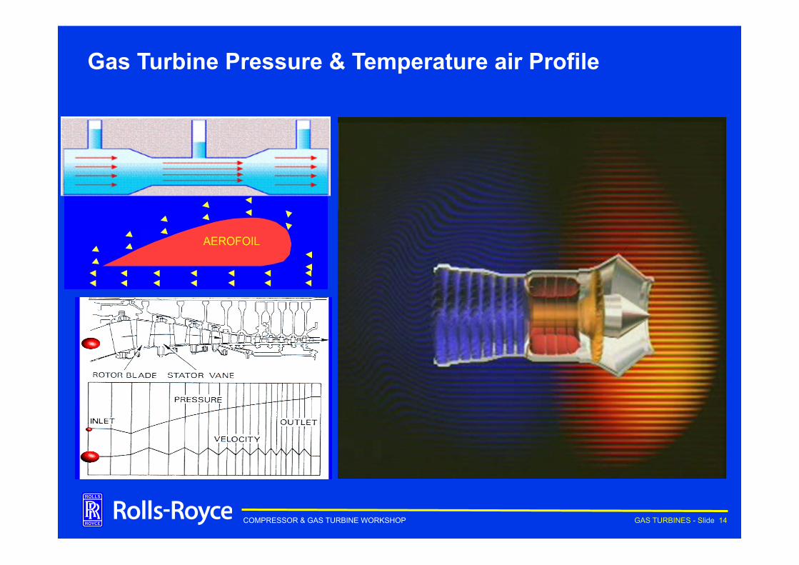
COMPRESSOR & GAS TURBINE WORKSHOP GAS TURBINES - Slide 14
Gas Turbine Pressure & Temperature air Profile
COMPRESSOR & GAS TURBINE WORKSHOP GAS TURBINES - Slide 15
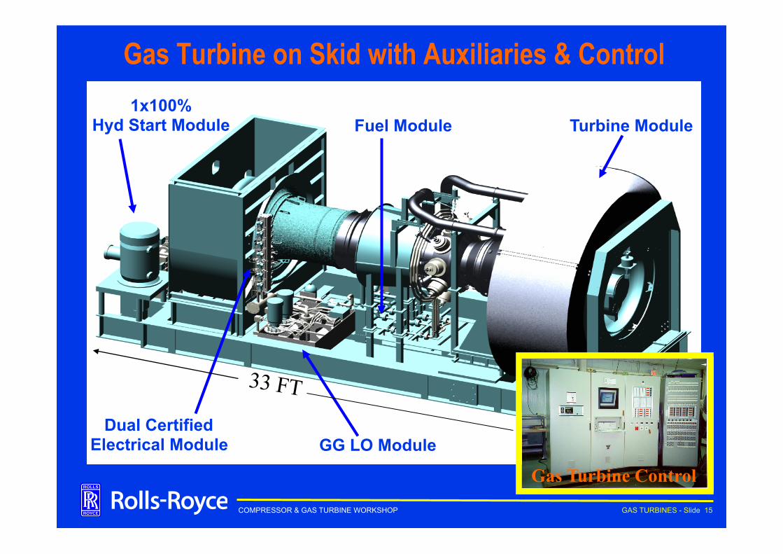
Gas Turbine on Skid with Auxiliaries & Control
GG LO Module
Fuel Module 1x100%
Hyd Start Module
Dual Certified Electrical Module
Turbine Module
Gas Turbine Control GG LO Module
Fuel Module 1x100%
Hyd Start Module
Dual Certified Electrical Module
Turbine Module
Gas Turbine Control
33 FT
COMPRESSOR & GAS TURBINE WORKSHOP GAS TURBINES - Slide 16
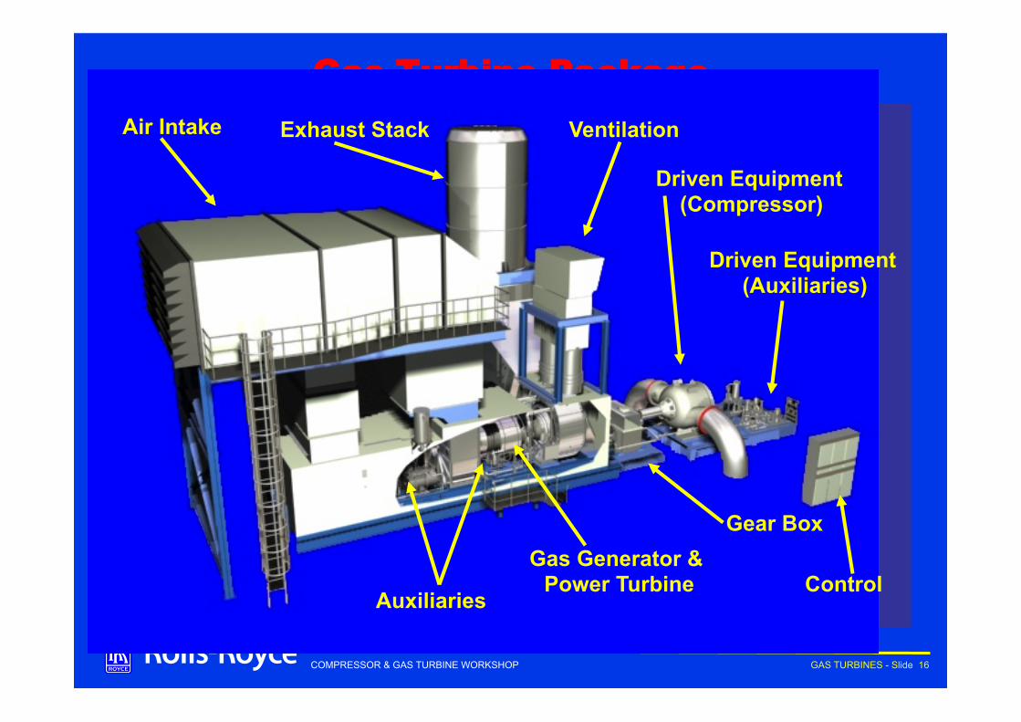
Gas Turbine Package Air Intake Exhaust Stack Ventilation
Driven Equipment (Compressor)
Driven Equipment (Auxiliaries)
Gear Box
Auxiliaries
Gas Generator & Power Turbine Control
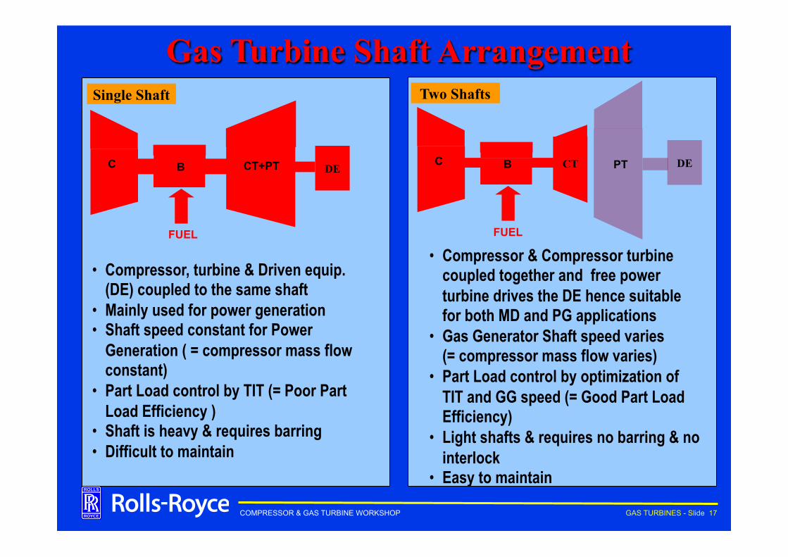
COMPRESSOR & GAS TURBINE WORKSHOP GAS TURBINES - Slide 17
• Compressor & Compressor turbine coupled together and free power turbine drives the DE hence suitable for both MD and PG applications
• Gas Generator Shaft speed varies (= compressor mass flow varies)
• Part Load control by optimization of TIT and GG speed (= Good Part Load Efficiency)
• Light shafts & requires no barring & no interlock
• Easy to maintain
Gas Turbine Shaft Arrangement
FUEL
CT C B DE PT
Two Shafts
FUEL
C B CT+PT
Single Shaft
DE
• Compressor, turbine & Driven equip. (DE) coupled to the same shaft
• Mainly used for power generation • Shaft speed constant for Power
Generation ( = compressor mass flow constant)
• Part Load control by TIT (= Poor Part Load Efficiency )
• Shaft is heavy & requires barring • Difficult to maintain
COMPRESSOR & GAS TURBINE WORKSHOP GAS TURBINES - Slide 18
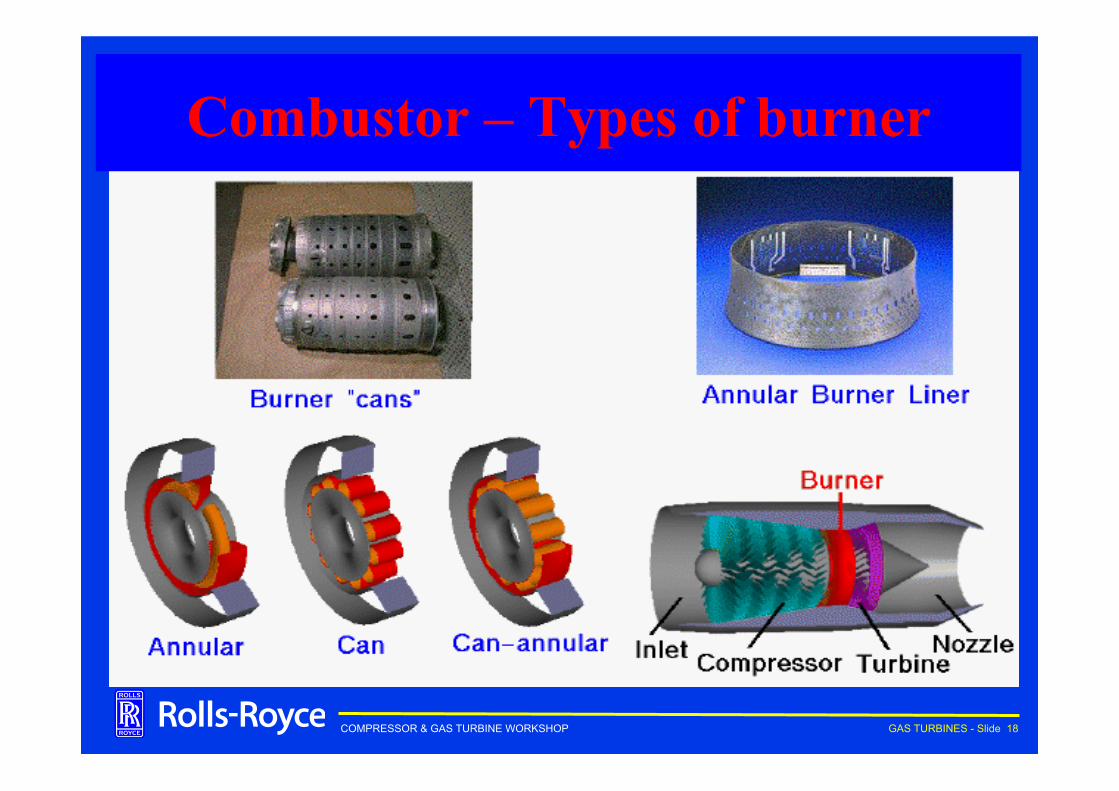
Combustor – Types of burner
COMPRESSOR & GAS TURBINE WORKSHOP GAS TURBINES - Slide 19
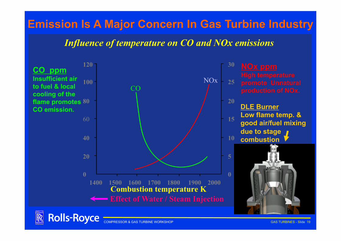
Influence of temperature on CO and NOx emissions
Combustion temperature K
NOx ppm High temperature promote Unnatural production of NOx.
CO ppm Insufficient air to fuel & local cooling of the flame promotes CO emission.
1400 1500 1600 1700 1800 1900 2000
120
100
80
60
40
20
0
30
25
20
15
10
5
0
NOx CO
Emission Is A Major Concern In Gas Turbine Industry
Effect of Water / Steam Injection
DLE Burner Low flame temp. & good air/fuel mixing due to stage combustion
COMPRESSOR & GAS TURBINE WORKSHOP GAS TURBINES - Slide 20
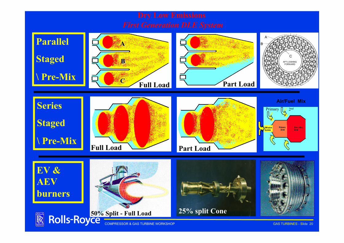
Dry Low Emissions First Generation DLE System
Combustion Module
Parallel
Staged
\ Pre-Mix Part Load Full Load
Part Load Full Load
Series
Staged
\ Pre-Mix
25% split Cone 50% Split - Full Load
EV & AEV burners
A
B
CAFT LOOKING
FORWARD
A
C
B
Primary 2nd
Air/Fuel Mix

COMPRESSOR & GAS TURBINE WORKSHOP GAS TURBINES - Slide 21
Agenda ➨ Gas Turbine ➨ Principles ➨ Construction ➨ Types & Applications
➨ Centrifugal Compressor ➨ Compressors Overview ➨ Performance Curves ➨ Applications
•
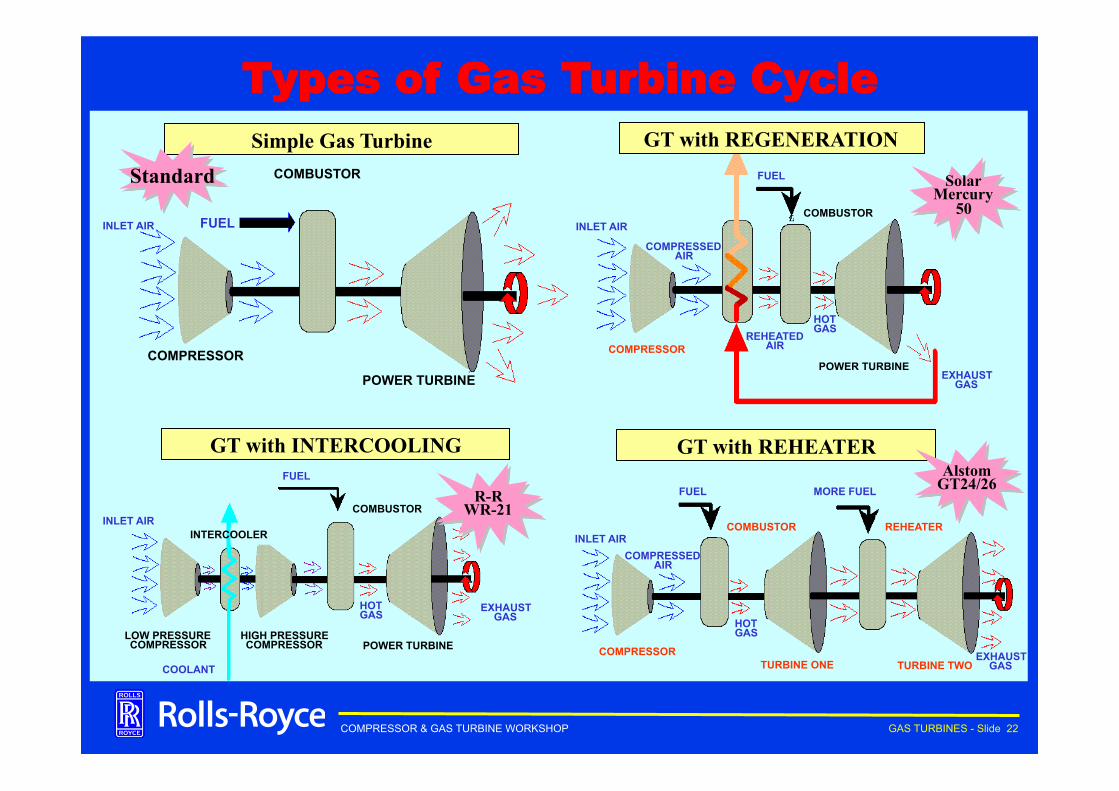
COMPRESSOR & GAS TURBINE WORKSHOP GAS TURBINES - Slide 22
Types of Gas Turbine Cycle
GT with INTERCOOLING
COMBUSTOR
HIGH PRESSURE COMPRESSOR POWER TURBINE
INTERCOOLER
LOW PRESSURE COMPRESSOR
INLET AIR
FUEL
HOT GAS
COOLANT
EXHAUST GAS
GT with REGENERATION
COMBUSTOR
POWER TURBINE COMPRESSOR
FUEL
INLET AIR
COMPRESSED AIR
REHEATED AIR
HOT GAS
EXHAUST GAS
GT with REHEATER
COMPRESSOR TURBINE ONE TURBINE TWO
COMBUSTOR REHEATER
FUEL MORE FUEL
INLET AIR COMPRESSED
AIR
HOT GAS
EXHAUST GAS
Simple Gas Turbine COMBUSTOR
COMPRESSOR
POWER TURBINE
FUEL INLET AIR
Standard Solar Mercury
50
R-R WR-21
Alstom GT24/26
COMPRESSOR & GAS TURBINE WORKSHOP GAS TURBINES - Slide 23
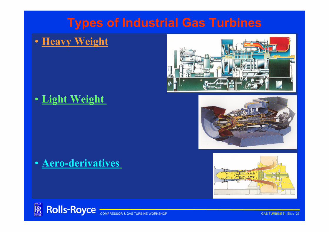
Types of Industrial Gas Turbines • Heavy Weight
• Light Weight
• Aero-derivatives
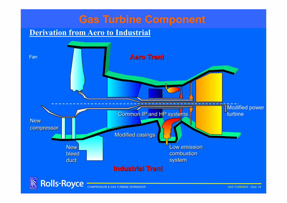
COMPRESSOR & GAS TURBINE WORKSHOP GAS TURBINES - Slide 24
New bleed duct
Modified casings
Low emission combustion system
Modified power turbine
Industrial Trent
Aero Trent
New compressor
Common IP and HP systems
Fan
Derivation from Aero to Industrial Aircraft Engine Lineage The Industrial Trent Gas Turbine Component
COMPRESSOR & GAS TURBINE WORKSHOP GAS TURBINES - Slide 25
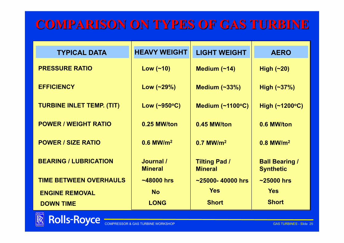
COMPARISON ON TYPES OF GAS TURBINE
TYPICAL DATA HEAVY WEIGHT LIGHT WEIGHT AERO
PRESSURE RATIO
EFFICIENCY
TURBINE INLET TEMP. (TIT)
POWER / WEIGHT RATIO
POWER / SIZE RATIO
TIME BETWEEN OVERHAULS
ENGINE REMOVAL
Low (~10)
Low (~29%)
Low (~950oC)
0.25 MW/ton
0.6 MW/m2
~48000 hrs
No
Medium (~14)
Medium (~33%)
Medium (~1100oC)
0.45 MW/ton
0.7 MW/m2
~25000- 40000 hrs Yes
High (~20)
High (~37%)
High (~1200oC)
0.6 MW/ton
0.8 MW/m2
~25000 hrs Yes
BEARING / LUBRICATION Journal / Mineral
Tilting Pad / Mineral
Ball Bearing / Synthetic
DOWN TIME LONG Short Short
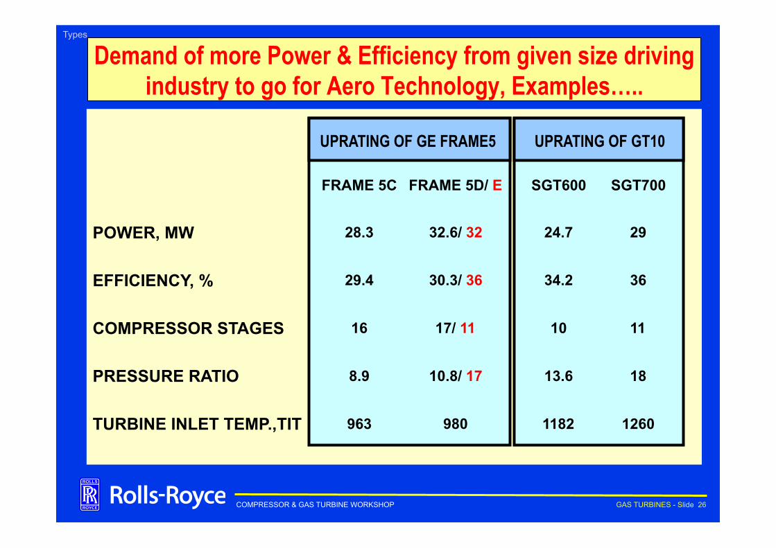
COMPRESSOR & GAS TURBINE WORKSHOP GAS TURBINES - Slide 26
POWER, MW
EFFICIENCY, %
COMPRESSOR STAGES
PRESSURE RATIO
TURBINE INLET TEMP.,TIT
FRAME 5C
28.3
29.4
16
8.9
963
FRAME 5D/ E
980
32.6/ 32
30.3/ 36
17/ 11
10.8/ 17
SGT600
1182
24.7
34.2
10
13.6
SGT700
1260
29
36
11
18
UPRATING OF GE FRAME5 UPRATING OF GT10
Demand of more Power & Efficiency from given size driving industry to go for Aero Technology, Examples…..
Types
COMPRESSOR & GAS TURBINE WORKSHOP GAS TURBINES - Slide 27
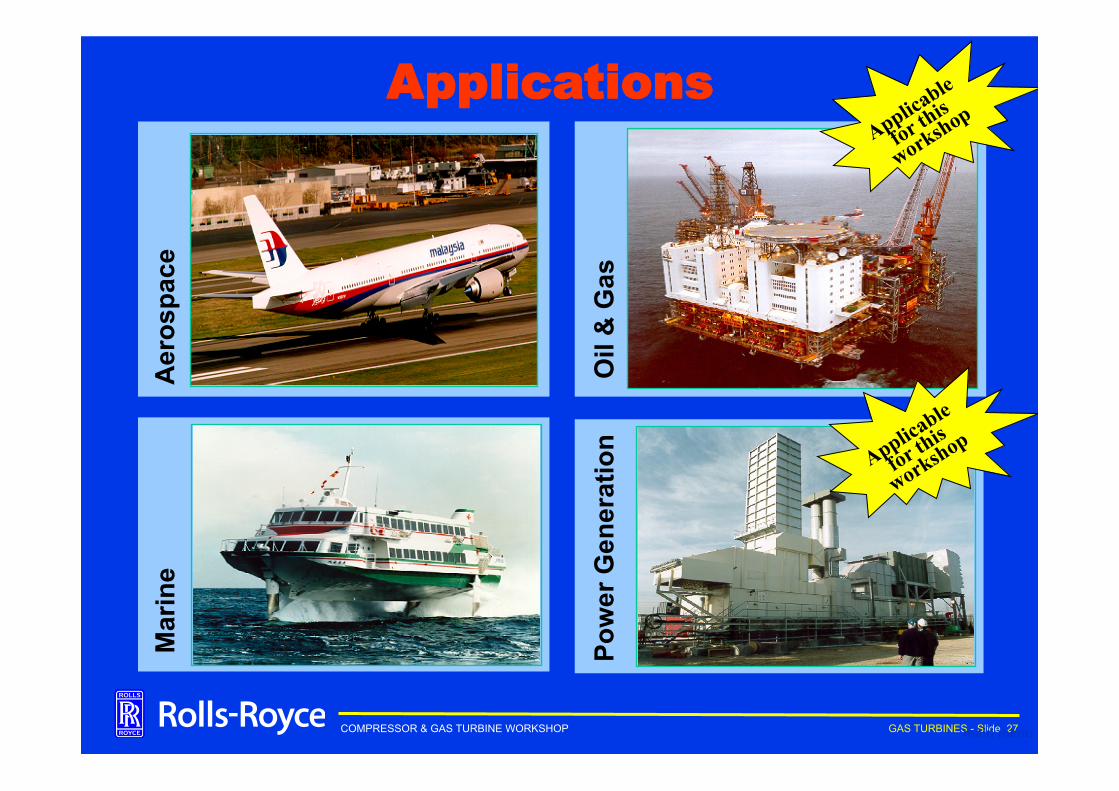
Applications
Pow
er G
ener
atio
n O
il &
Gas
main menu
Mar
ine
Aer
ospa
ce
COMPRESSOR & GAS TURBINE WORKSHOP GAS TURBINES - Slide 28
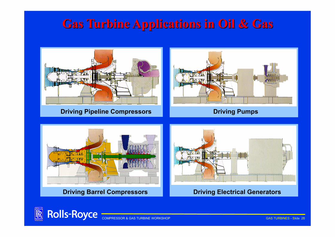
Driving Pipeline Compressors Driving Pumps
Driving Barrel Compressors Driving Electrical Generators
Gas Turbine Applications in Oil & Gas
COMPRESSOR & GAS TURBINE WORKSHOP GAS TURBINES - Slide 29
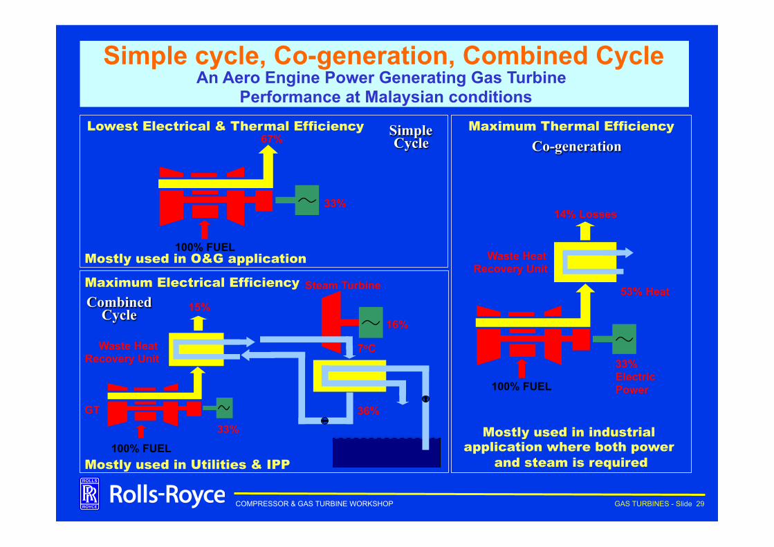
Simple cycle, Co-generation, Combined Cycle An Aero Engine Power Generating Gas Turbine
Performance at Malaysian conditions
14% Losses
Waste Heat Recovery Unit
53% Heat
33% Electric Power 100% FUEL
GT
33% 100% FUEL
15%
Waste Heat Recovery Unit
16%
Steam Turbine
7oC
36%
67%
33%
100% FUEL Mostly used in O&G application
Maximum Electrical Efficiency
Lowest Electrical & Thermal Efficiency
Mostly used in Utilities & IPP
Maximum Thermal Efficiency
Mostly used in industrial application where both power
and steam is required
Simple Cycle Co-generation
Combined Cycle
COMPRESSOR & GAS TURBINE WORKSHOP GAS TURBINES - Slide 30
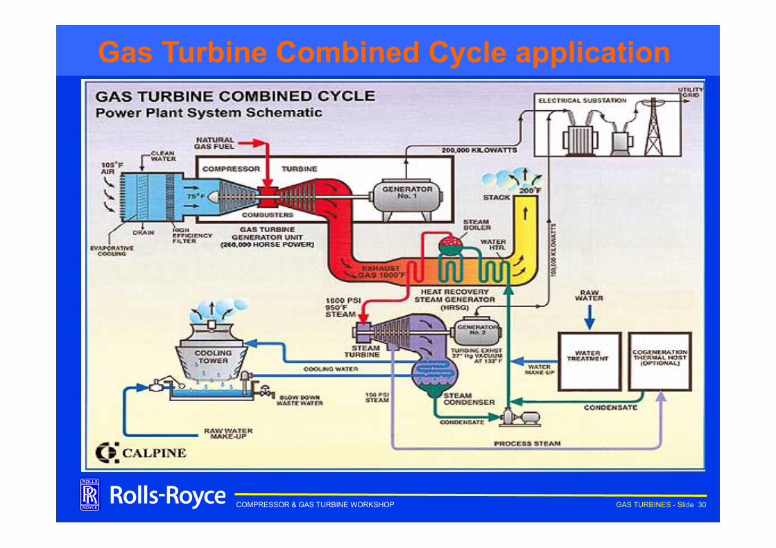
Aircraft Engine Lineage The Industrial Trent Gas Turbine Combined Cycle application
COMPRESSOR & GAS TURBINE WORKSHOP GAS TURBINES - Slide 31
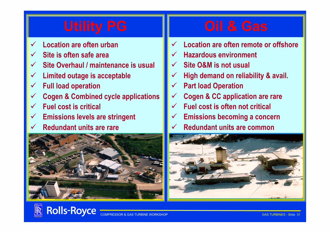
Utility PG ü Location are often urban ü Site is often safe area ü Site Overhaul / maintenance is usual ü Limited outage is acceptable ü Full load operation ü Cogen & Combined cycle applications ü Fuel cost is critical ü Emissions levels are stringent ü Redundant units are rare
Oil & Gas ü Location are often remote or offshore ü Hazardous environment ü Site O&M is not usual ü High demand on reliability & avail. ü Part load Operation ü Cogen & CC application are rare ü Fuel cost is often not critical ü Emissions becoming a concern ü Redundant units are common

COMPRESSOR & GAS TURBINE WORKSHOP GAS TURBINES - Slide 32
COMPRESSOR & GAS TURBINE WORKSHOP GAS TURBINES - Slide 33
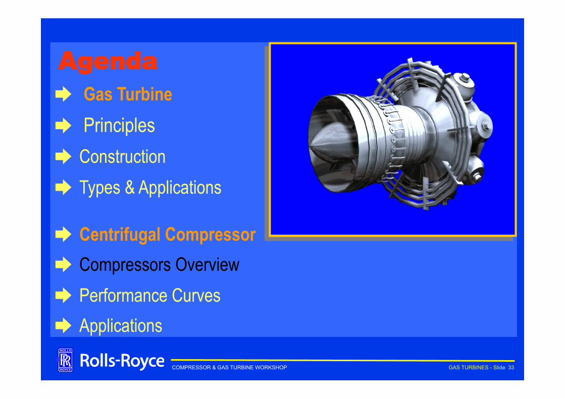
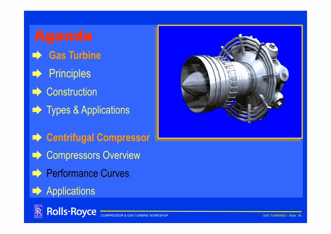
Agenda ➨ Gas Turbine ➨ Principles ➨ Construction ➨ Types & Applications
➨ Centrifugal Compressor ➨ Compressors Overview ➨ Performance Curves ➨ Applications
•
COMPRESSOR & GAS TURBINE WORKSHOP GAS TURBINES - Slide 34
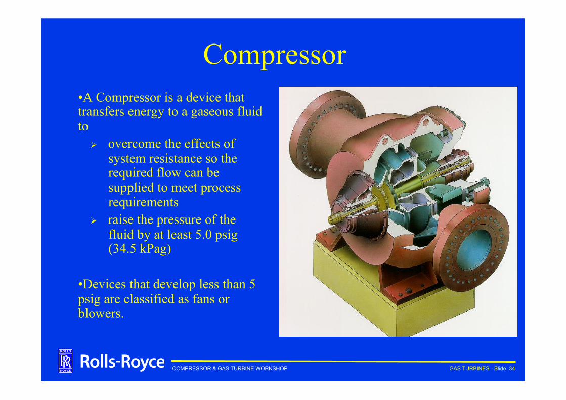
Compressor • A Compressor is a device that transfers energy to a gaseous fluid to
Ø overcome the effects of system resistance so the required flow can be supplied to meet process requirements
Ø raise the pressure of the fluid by at least 5.0 psig (34.5 kPag)
• Devices that develop less than 5 psig are classified as fans or blowers.
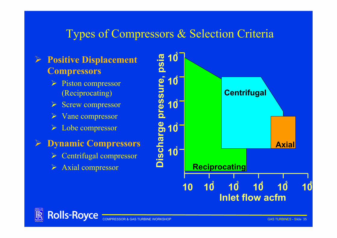
COMPRESSOR & GAS TURBINE WORKSHOP GAS TURBINES - Slide 35
Types of Compressors & Selection Criteria
Ø Positive Displacement Compressors Ø Piston compressor
(Reciprocating) Ø Screw compressor Ø Vane compressor Ø Lobe compressor
Ø Dynamic Compressors Ø Centrifugal compressor Ø Axial compressor D
isch
arge
pre
ssur
e, p
sia
Inlet flow acfm
10 1
10 5
10 4
10 3
10 2
10 10 5 10 4 10 3 10 2 10 6
Reciprocating
Centrifugal
Axial
COMPRESSOR & GAS TURBINE WORKSHOP GAS TURBINES - Slide 36
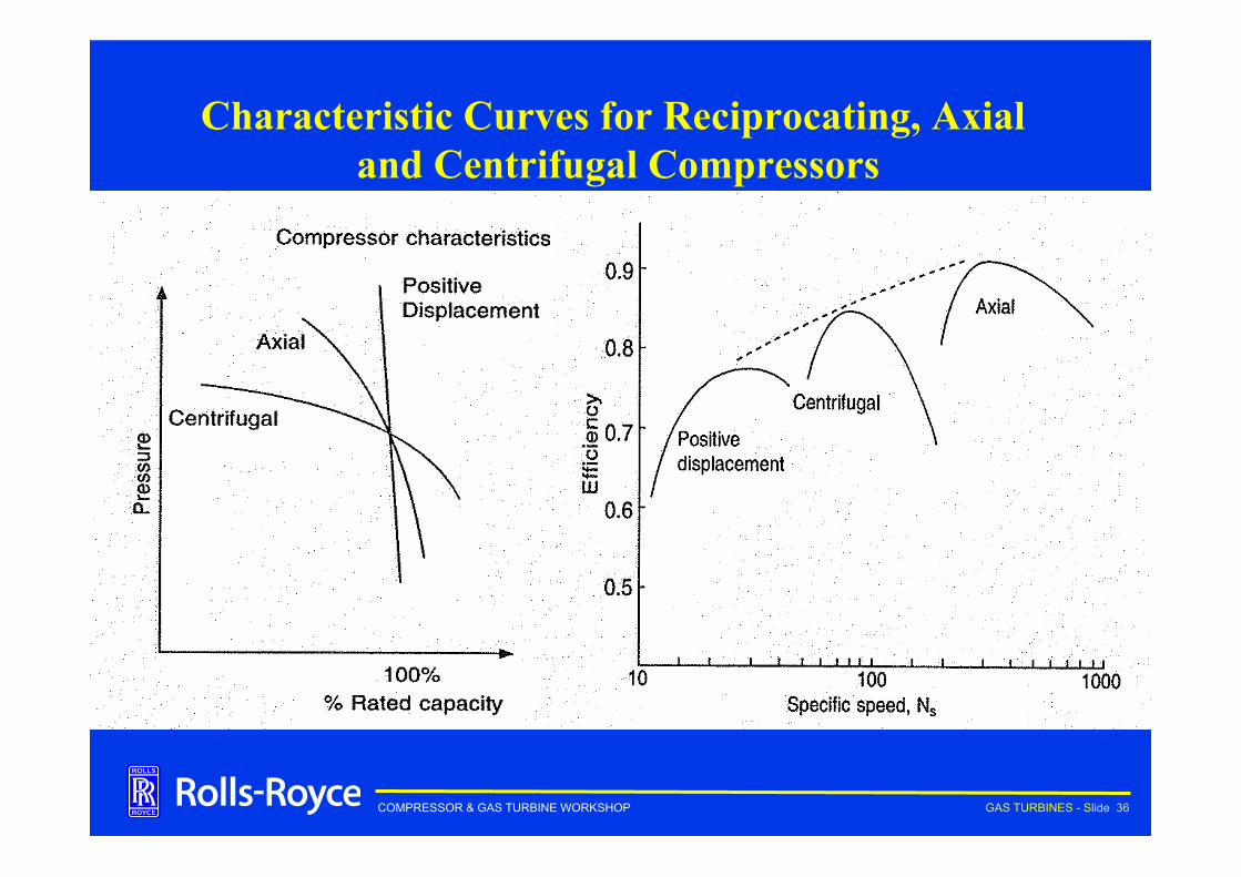
Characteristic Curves for Reciprocating, Axial and Centrifugal Compressors
COMPRESSOR & GAS TURBINE WORKSHOP GAS TURBINES - Slide 37
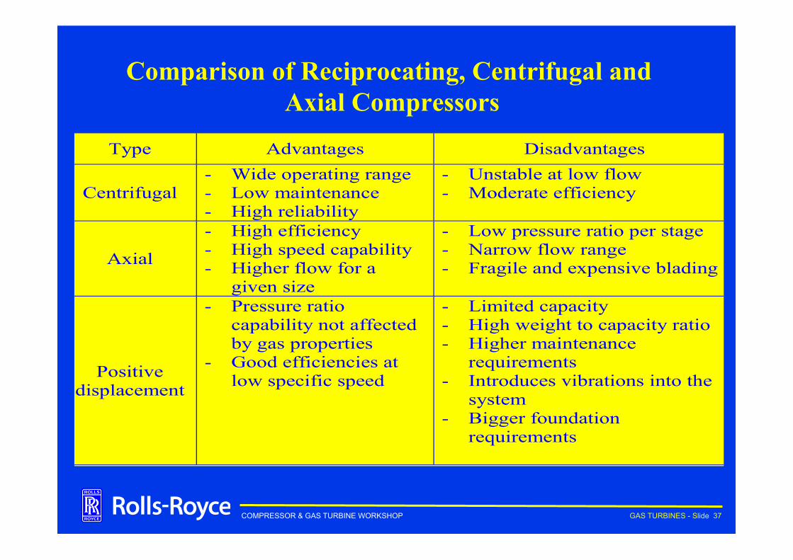
Comparison of Reciprocating, Centrifugal and Axial Compressors
Type Advantages Disadvantages
Centrifugal- Wide operating range- Low maintenance- High reliability
- Unstable at low flow- Moderate efficiency
Axial
- High efficiency- High speed capability- Higher flow for a
given size
- Low pressure ratio per stage- Narrow flow range- Fragile and expensive blading
Positivedisplacement
- Pressure ratiocapability not affectedby gas properties
- Good efficiencies atlow specific speed
- Limited capacity- High weight to capacity ratio- Higher maintenance
requirements- Introduces vibrations into the
system- Bigger foundation
requirements
COMPRESSOR & GAS TURBINE WORKSHOP GAS TURBINES - Slide 38
Agenda ➨ Gas Turbine ➨ Principles ➨ Construction ➨ Types & Applications
➨ Centrifugal Compressor ➨ Compressors Overview ➨ Performance Curves ➨ Applications
•
COMPRESSOR & GAS TURBINE WORKSHOP GAS TURBINES - Slide 39
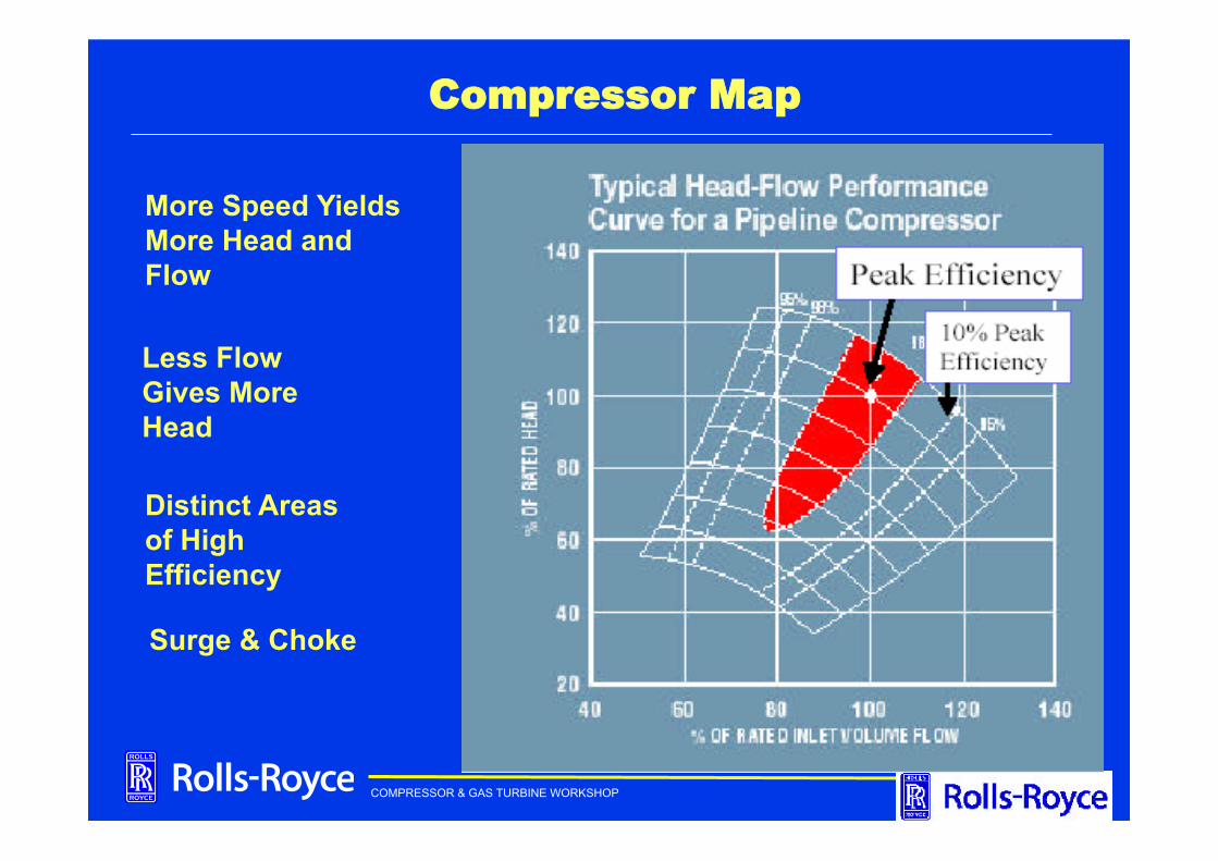
Compressor Map
More Speed Yields More Head and Flow
Less Flow Gives More Head
Distinct Areas of High Efficiency
Surge & Choke
COMPRESSOR & GAS TURBINE WORKSHOP GAS TURBINES - Slide 40
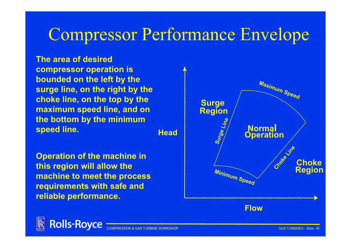
Compressor Performance Envelope
Head
Flow
Choke Region
Normal Operation
Minimum Speed
Surge Region
The area of desired compressor operation is bounded on the left by the surge line, on the right by the choke line, on the top by the maximum speed line, and on the bottom by the minimum speed line.
Operation of the machine in this region will allow the machine to meet the process requirements with safe and reliable performance.
COMPRESSOR & GAS TURBINE WORKSHOP GAS TURBINES - Slide 41
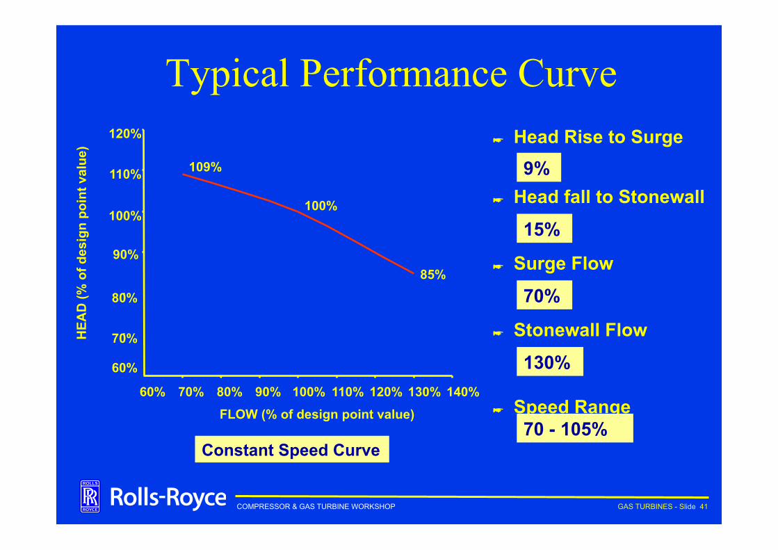
Typical Performance Curve
109%
100%
85%
60%
70%
80%
100%
110%
120%
60% 70% 80% 90% 100% 110% 120% 130% 140% FLOW (% of design point value)
HEA
D (%
of d
esig
n po
int v
alue
)
90%
☛ Head Rise to Surge
☛ Head fall to Stonewall
☛ Surge Flow
☛ Stonewall Flow
☛ Speed Range
9%
15%
70%
130%
70 - 105% Constant Speed Curve
COMPRESSOR & GAS TURBINE WORKSHOP GAS TURBINES - Slide 42
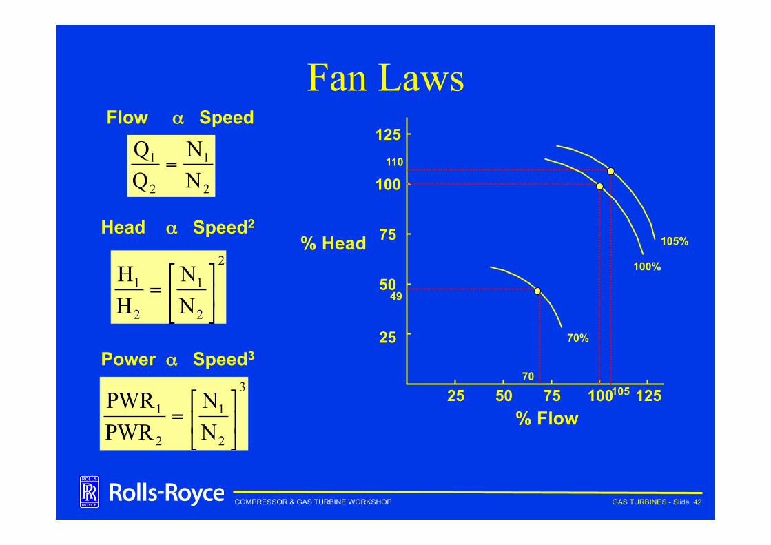
Fan Laws Flow α Speed
2
1
2
1
NN
=
2
2
1
2
1
NN
HH
⎥⎦
⎤⎢⎣
⎡=
3
2
1
2
1
NN
PWRPWR
⎥⎦
⎤⎢⎣
⎡=
Head α Speed2
Power α Speed3
% Head
% Flow
25
100 75 50 25
100
75
50 100%
125 110
125 105
105%
70%
70
49
COMPRESSOR & GAS TURBINE WORKSHOP GAS TURBINES - Slide 43
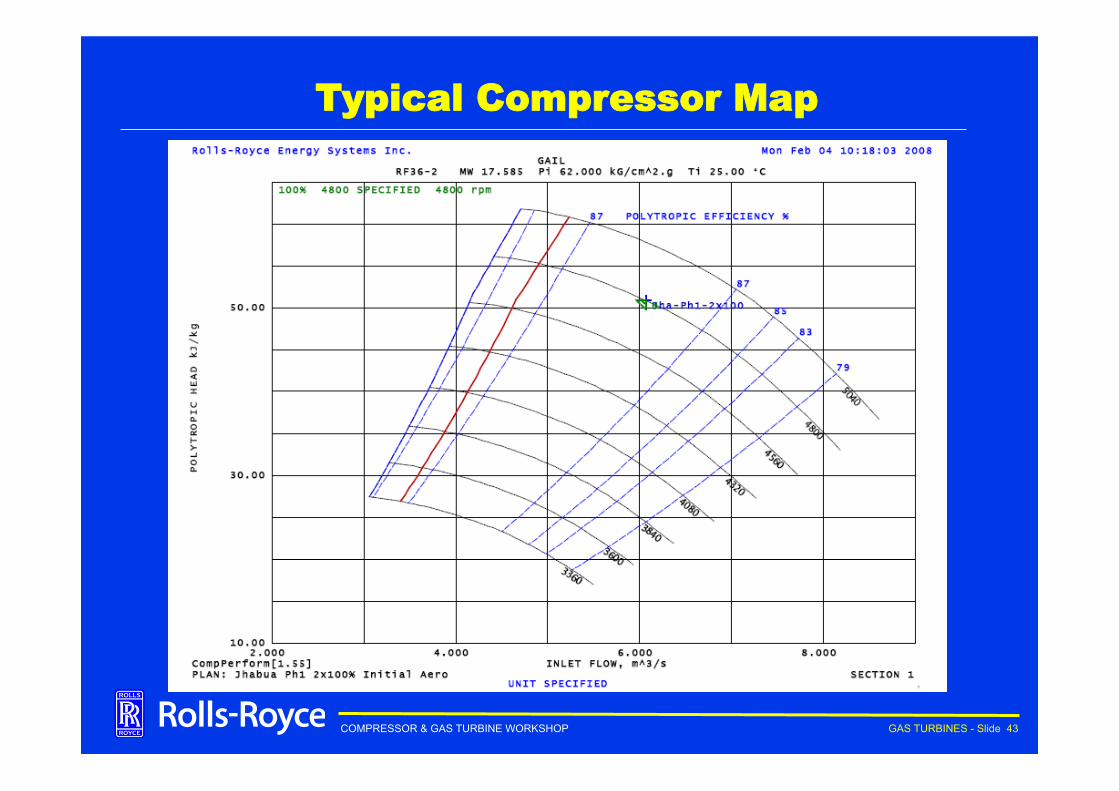
Typical Compressor Map
COMPRESSOR & GAS TURBINE WORKSHOP GAS TURBINES - Slide 44
Agenda ➨ Gas Turbine ➨ Principles ➨ Construction ➨ Types & Applications
➨ Centrifugal Compressor ➨ Compressors Overview ➨ Performance Curves ➨ Applications
•
COMPRESSOR & GAS TURBINE WORKSHOP GAS TURBINES - Slide 45
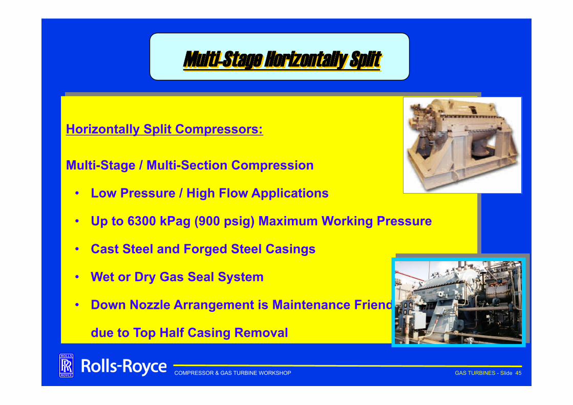
Multi-Stage Horizontally Split
Horizontally Split Compressors:
Multi-Stage / Multi-Section Compression
• Low Pressure / High Flow Applications
• Up to 6300 kPag (900 psig) Maximum Working Pressure
• Cast Steel and Forged Steel Casings
• Wet or Dry Gas Seal System
• Down Nozzle Arrangement is Maintenance Friendly
due to Top Half Casing Removal
COMPRESSOR & GAS TURBINE WORKSHOP GAS TURBINES - Slide 46
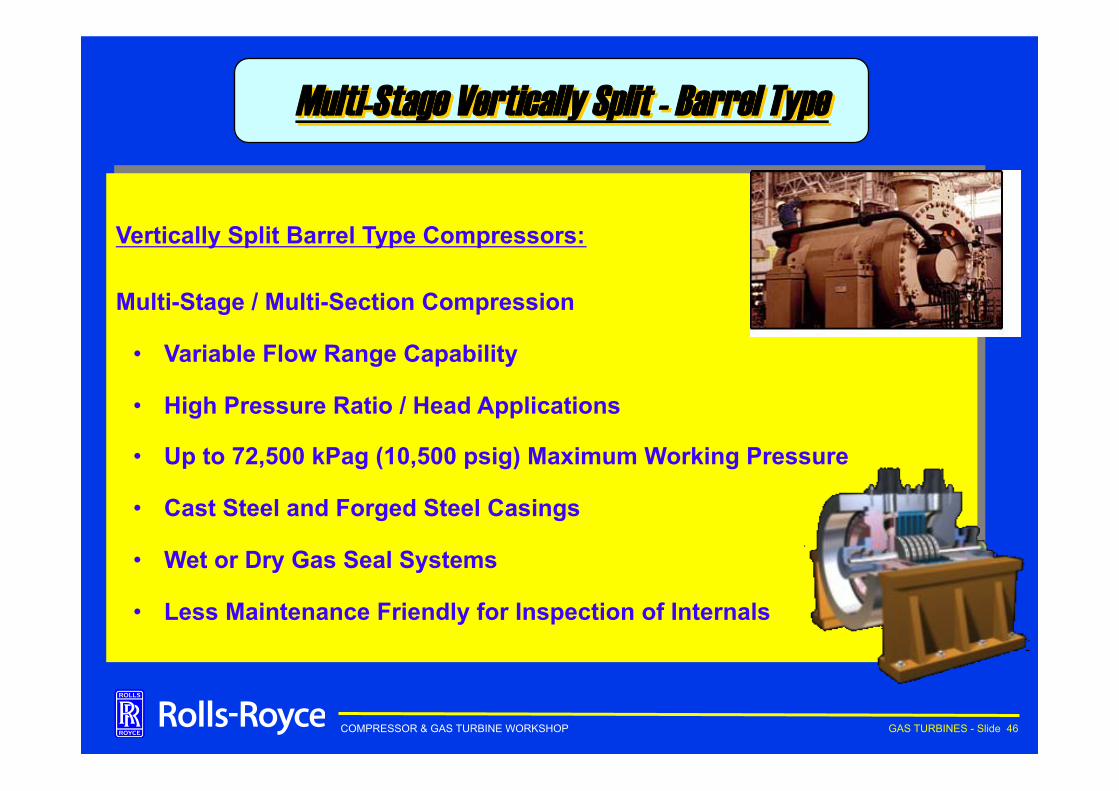
Vertically Split Barrel Type Compressors:
Multi-Stage / Multi-Section Compression
• Variable Flow Range Capability
• High Pressure Ratio / Head Applications
• Up to 72,500 kPag (10,500 psig) Maximum Working Pressure
• Cast Steel and Forged Steel Casings
• Wet or Dry Gas Seal Systems
• Less Maintenance Friendly for Inspection of Internals
Multi-Stage Vertically Split - Barrel Type
COMPRESSOR & GAS TURBINE WORKSHOP GAS TURBINES - Slide 47
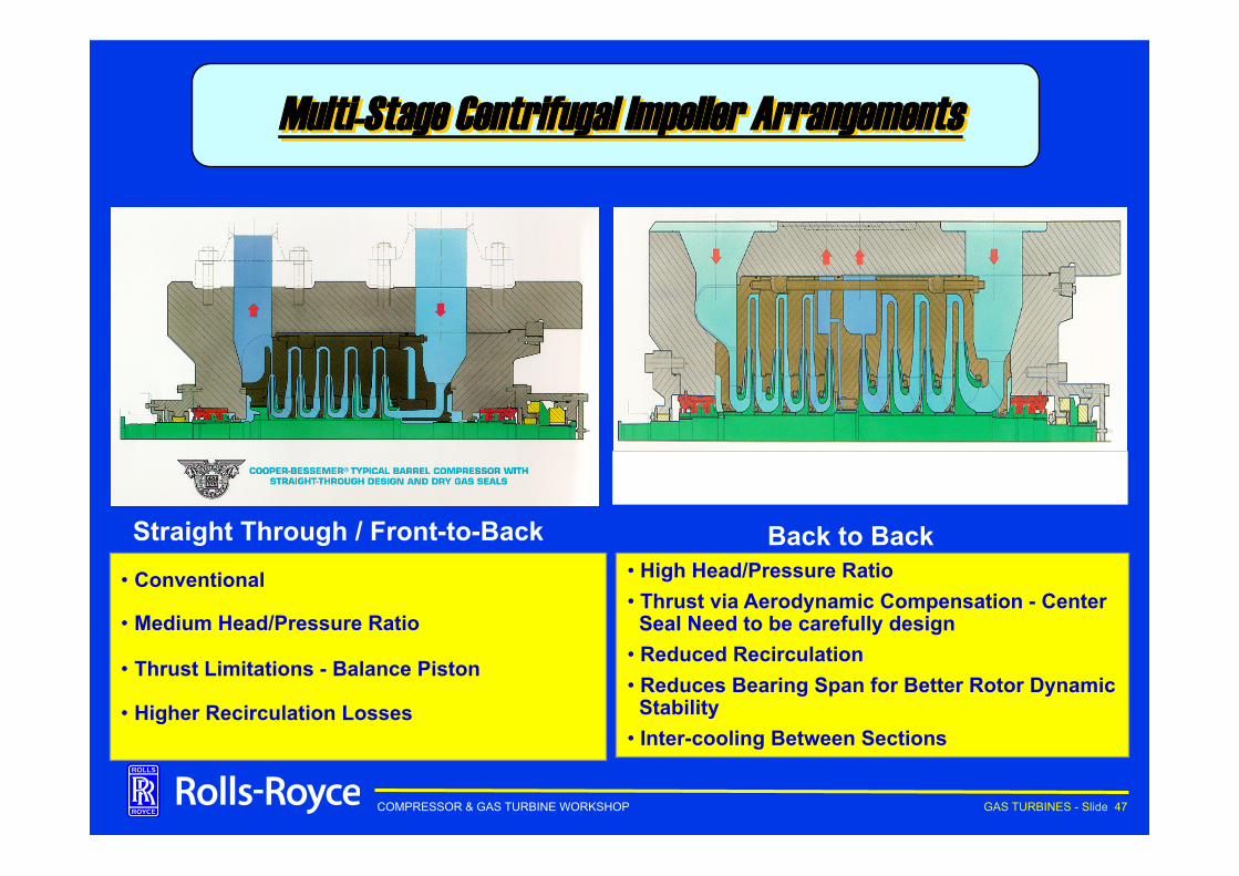
Multi-Stage Centrifugal Impeller Arrangements
• High Head/Pressure Ratio • Thrust via Aerodynamic Compensation - Center
Seal Need to be carefully design • Reduced Recirculation • Reduces Bearing Span for Better Rotor Dynamic
Stability • Inter-cooling Between Sections
• Conventional
• Medium Head/Pressure Ratio
• Thrust Limitations - Balance Piston
• Higher Recirculation Losses
Straight Through / Front-to-Back Back to Back
COMPRESSOR & GAS TURBINE WORKSHOP GAS TURBINES - Slide 48
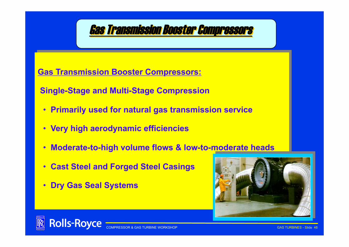
Gas Transmission Booster Compressors:
Single-Stage and Multi-Stage Compression
• Primarily used for natural gas transmission service
• Very high aerodynamic efficiencies
• Moderate-to-high volume flows & low-to-moderate heads
• Cast Steel and Forged Steel Casings
• Dry Gas Seal Systems
Gas Transmission Booster Compressors
COMPRESSOR & GAS TURBINE WORKSHOP GAS TURBINES - Slide 49
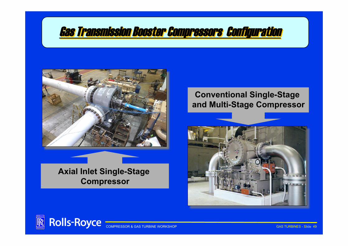
Axial Inlet Single-Stage Compressor
Conventional Single-Stage and Multi-Stage Compressor
Gas Transmission Booster Compressors Configuration
COMPRESSOR & GAS TURBINE WORKSHOP GAS TURBINES - Slide 50
Centrifugal Gas Transmission Boosters
Conventional: • Horizontally opposed nozzles/side inlet • Between bearings (and overhung) rotor designs • Wide pressure ratio/head flexibility - up to five stages • High aerodynamic efficiencies - 88% polytropic • Fixed casing design per frame size • Fixed pressure ratings up to 17,240 kPag (2500 psig)
Axial Inlet: • Highest aerodynamic efficiencies - Near 90% isentropic • Limited to single-stage designs (1.45:1 Pressure Ratio) • Overhung rotor design (single dry gas seal design) • Pressures up to 12,410 kPag (1800 psig) • Fixed casing design per frame size
COMPRESSOR & GAS TURBINE WORKSHOP GAS TURBINES - Slide 51
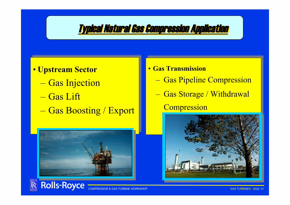
• Upstream Sector
– Gas Injection – Gas Lift – Gas Boosting / Export
• Gas Transmission
– Gas Pipeline Compression
– Gas Storage / Withdrawal Compression
Typical Natural Gas Compression Application

COMPRESSOR & GAS TURBINE WORKSHOP GAS TURBINES - Slide 52
Next …..
Q & A


![Preparation and Characterization of Cyano Complexes of ...downloads.hindawi.com/journals/jchem/2010/378561.pdf · Preparation of (Ph 3P) 2NH 2[WO(CN) 3L–L].3H 2O (Ph 3P) 2NH 2[WO(CN)](https://img.pdfslide.us/doc/110x75/60893efe64f7142ce10196ee/preparation-and-characterization-of-cyano-complexes-of-preparation-of-ph-3p.jpg)