Embed Size (px)
Citation preview
8/11/2019 2.Model Relations Between Conceptual and Detail Design
http://slidepdf.com/reader/full/2model-relations-between-conceptual-and-detail-design 1/8
Model relations between conceptual and detail design
R. Scheidl a,*, B. Winkler b
a Institute of Machine Design and Hydraulic Drives, Johannes Kepler University Linz, Altenbergestraße 69, 4040 Linz, Austriab Linz Center of Mechatronics, GmbH, Altenbergestraße 69, 4040 Linz, Austria
a r t i c l e i n f o
Keywords:
Model based conceptual design
Design map
Model relations
a b s t r a c t
Conceptual design, as an essential step towards successful mechatronic product development, should be
supported by good models for the design map, which in turn expresses the relationship between thedesign parameters and the functional requirements. If feasible, these models should be mathematical.
In this paper the close correlation between a good concept and its models is postulated. A theory is pre-
sented howthese models are related to models employed for detail design and howgood concept models
can be characterised. The practical realisation of this characterisation relies on the decomposability of the
whole design map in several low dimensional decoupled parts. This corresponds to Suh’s independence
axiom. Modelling aspects of the development of an energy saving hydraulic variable valve train for com-
bustion engines are used as a demonstrative example.
2010 Elsevier Ltd. All rights reserved.
1. Introduction
The decisive role of conceptual design in successful product
development has sufficiently been highlighted in the design litera-ture. This is even more relevant for mechatronic systems, since the
mechatronics architecture is largely defined in conceptual design.
Consequently, numerous methods were proposed to support the
conceptual design work. Among these different methods, model-
ling and simulation and concept evaluation techniques play a ma-
jor role. For mechatronic systems, modelling and simulation in
conceptual design have been emphasized stronger than, for in-
stance, in mechanical engineering, particularly in the late 1980s
and 1990s when academic mechatronics research became popular
in Europe (see, e.g., [1–4]). The terms ‘modelling’ and ‘simulation’
in the context of mechatronic system design are generally under-
stood as modelling of dynamical systems and their numerical sim-
ulation. This reflects the strong role of dynamical aspects and of
control in such systems. Quite often, such models are not related
to a specific design phase (conceptual or detail) but are considered
as models par excellence for that system. If it comes to the devel-
opment of particular components or sub-systems, modelling of
other aspects, like strength or stiffness by, e.g., Finite Elements, is
frequently reported in the scientific mechatronics literature,
though (see, e.g., [5,6]).
Particularly in industrial practice, the organisation of the total
design process is oriented to final product definition and not to
maintenance of the design concept. This is the reason why no gen-
eral standards exist to describe concepts effectively. An attempt to
develop a general notation of sketching in mechanical design [7]
did not find a broad acceptance. Conceptual design and related
modelling strategies are crucial in product development. Not onlythey generate important information for detail design but are also
strong fundamentals for the whole life cycle of a product including
all its design revisions.
There are at least two types of feed-back loops that are usually
acknowledged in design literature and that play an important role
in practice: (i) the iterative design cycles that are often necessary
since design is seldom a straight-forward process and (ii) the great
roleof design experience (see, e.g.,[8,9]) that includes also detail de-
sign experience. Both of these feed-back loops transfer information
from detail design to concept design. But hardly any rule or theory
can be found on model relations between conceptual and detail de-
sign. This probably stems from the different types and functions of
models and the respective tools in these different design phases.
There is no design activity without models, if the model defini-
tion of Thompson [10] is adopted which states (citation)
‘‘ All humans model. We build these models within ourselves as a
template for what to anticipate under the varied condition of our
daily experience.”
In the following, a more specific definition of models will be ap-
plied, namely formal models, in particular mathematical ones. The
use of these in conceptual design has a long tradition dating back
to the origins of scientific engineering (see for instance, the
19th century statement of F. Redtenbacher1 about the benefit of
0957-4158/$ - see front matter 2010 Elsevier Ltd. All rights reserved.doi:10.1016/j.mechatronics.2010.04.008
* Corresponding author. Tel.: +43 732 2468 9745; fax: +43 732 2468 9753.
E-mail address: [email protected] (R. Scheidl).
1 Ferdinand Redtenbacher (1809–1863), Prof. of Machine Design at Karlsruhe
Technical University is reckoned as a founder of mechanical engineering science.
Mechatronics 20 (2010) 842–849
Contents lists available at ScienceDirect
Mechatronics
j o u r n a l h o m e p a g e : w w w . e l s e v i e r . c o m / l o c a t e / m e c h a t r o n i c s
8/11/2019 2.Model Relations Between Conceptual and Detail Design
http://slidepdf.com/reader/full/2model-relations-between-conceptual-and-detail-design 2/8
mathematical modelling in [11]). Traditionally, mathematical mod-
els account for the physical limitations of the design with an appro-
priate level of accuracy [10]. Several proposals exist to also exploit
some qualitative properties of these models for concept evaluation.
A prominent method is Suh’s Axiomatic Design [12,13] which stres-
ses the simplicity of the relation between the design parameters
(DPs) and the functional requirements (FRs) for a successful product
design in its 1st design axiom. This relation is called design map(DM) in the following. In his publications Suh does not explicitly de-
clare that his 1st design axiom is to be applied in conceptual design.
But the axiom’s characteristics and the corresponding examples in
Suh’s publications suggest this. Other methods are related to a qual-
itative assessment of the mathematical models structure, such as
that by Steiner and Scheidl [14] which uses Friedmann’s constraint
theory [15] to analyze the complexity of the DM. But the relationship
between models of conceptual and detail design is not addressed in
either of these papers.
In Dierneder and Scheidl [16] the model relations between dif-
ferent design phases are addressed. It states that a good concept
has the property that the DM at the detail design level (DMdetail)
is only a regular perturbation of the DM at the concept level
(DMconcept). Without explaining perturbation theory (see, for in-
stance [17]) in detail this means that DMdetail becomes exactly
DMconcept if those parameters which account for the modelling dif-
ferences tend to zero. This conjecture is not further elaborated in
Dierneder and Scheidl [16] since it focuses more on the functional
decomposition method. Furthermore, the use of perturbation the-
ory in the practical application of this conjecture is mostly imprac-
tical for people inexperienced in its use. Perturbation theory needs
a dimensionless formulation of the mathematical relations, the
identification of one or another small parameter, and a sound
understanding of qualitative mathematical properties of the rela-
tions under study, e.g. the qualitative theory of differential
equations.
It should be mentioned that good modelling, particularly for
conceptual design, is a formidable task. It requires familiarity with
the relevant physics, the structure of the model and how it oper-ates in that design problem. There is a latent danger of model defi-
ciencies, particularly if familiar models are used for cases which
are outside their validity range. If such model misuse is lately dis-
covered in the development process, this may cause large extra
costs. All this favours a culture of a steady improvement and main-
tenance of concept models.
The idea to exploit model relations of conceptual and detail de-
sign as a means to assess the validity of a concept and to improve
concept models will be discussed in this paper. Together with this
the authors would also like to promote a symbiotic concurrence of
hands-on activities, experience, and creativity on the one hand and
formal, model based, systematic approaches on the other hand.
This concurrence is needed for successful and innovative solution
of today’s often complex design problems.In the following section the characteristics of a good concept are
discussed and how this is related to detail design. In Section 3 the
nature of model relations will be worked out and in Section 4 the
exploitation of this theory is demonstrated showing the develop-
ment of a hydraulic variable valve train for gas engines.
2. Characteristics of a good concept
It is common understanding that product development happens
in cycles. Ideas have to be brought up, evaluated, and modified or
replaced – if necessary. Many designers start with some abstract
idea of the solution – called concept. At first they work with func-
tions and specify technical realisations of the functions rather late-
ly. This approach is called function analysis [9,18]. The overall
function is composed by several sub-functions called functional
elements (FE) [19], which, if so, can be further decomposed until
one ends up with no more decomposable functions, called essential
sub-functions by Cross [8] or elementary functions by Roozenburg
and Eekels [9]. The concept is further characterised by the interac-
tion structure of these FE, called the architecture of the concept or
its function structure [18]. Functions typically operate in the phys-
ical space if we limit our considerations to mechanical or electrical
systems and disregard information functions. Typical elementary
functions are, e.g., drive a rotary load, amplify an electrical current,
or guide a mechanical system along a straight line. Physical laws
and DPs can be associated with such functions, e.g. the moment
of momentum equation and the rotary inertia. Mathematical mod-
els of these concepts can be derived from physical laws. With these
models and estimates of some of the DPs the fulfilment of the FRs
and of boundary conditions (BCs) (e.g., that the system has suffi-
cient mechanical strength) can be assessed quantitatively. In best
case, the inverse of the DM (DM(1)) can be derived explicitly. This
enables a very efficient concept evaluation because the DPs for gi-
ven FRs can be determined directly without any iteration. Further-
more, the systemrobustness (how do FRs change with variations in
the DPs) can be assessed easily. Of course, existence of DM(1), re-
quires equal numbers of DPs and FRs (if applicable, plus BCs). It is
obvious that the quality of the design assessment depends on the
significance of the models and of the DP estimates. The latter is
very critical if the estimated material parameters or manufacturing
methods are close to technological limits. Then no reserve exists to
compensate the mostly downgrading influence on system perfor-
mance by effects not covered by the simple concept model.
Since the final technical realisation is not fully known, the con-
cept models are always idealised and cannot account for effects
that are created by details of the technical realisation. Nonetheless,
some of these effects can be anticipated from experience and can
be approximated in the concept model.
No clear borderline between conceptual and detail design exists
[8]. There is just a gradual change fromthe abstract to the concrete
which happens in several levels depending on the complexity of the system under development. A rotary drive, for example, can
be one out of several types of electrical or hydraulic motors, all
having different characteristics concerning their own rotary iner-
tia, thermal behaviour, controllability, etc. It is not clear if the spec-
ification of the motor type is part of concept definition or not.
Obviously, leaving it open enlarges the solution space, specifying
it enables a more reliable assessment of the concept. But what else
is a good concept, if it cannot even be defined sharply? It has to ful-
fil the following demands:
1. A good concept should enable a fast and cheap further develop-
ment of the product which meets the FRs and fulfils the BCs.
This is achieved if the number of design cycles can be kept
low and the detail design does not decisively debase what theconcept models promise with respect to the fulfilment of the
FRs and BCs.
2. It should facilitate a cheap and reliable production and exhibit
sufficient potential for easy and reliable product modifications
in the future. Such modifications may become necessary to
account for changed performance characteristics, to exploit
new or improved technologies (e.g., a new positioning drive
technology offering higher precision), or to add new product
features requested by the market.
What is stated in both demands can be condensed to one ‘con-
cept robustness requirement’:
Robustness of the concept with respect to detail design for a fairly
wide performance range.
R. Scheidl, B. Winkler/ Mechatronics 20 (2010) 842–849 843
8/11/2019 2.Model Relations Between Conceptual and Detail Design
http://slidepdf.com/reader/full/2model-relations-between-conceptual-and-detail-design 3/8
Concept model development which finally leads to the DM is
influenced by both demand categories listed above. The concept
robustness requirement also has to hold for the concept models
since they are part of the concept. But how can this robustness
be checked in view of the different nature of models in concept
and detail design? This is analysed in the next section.
3. Model relations
Models in concept phase and detail design phase have quite dif-
ferent properties. In concept phase they provide the whole view,
concentrate on the main effects, are coarse, and manage with a
smaller number of DPs, whereas in detail design they are more fo-
cussed on specific effects, are more accurate, and need much more
parameters.
When the detail design is done the predictions of the concept
model(s) can be controlled by more refined models, e.g. in case
of a hydraulic variable valve train, by a numerical model in Mat-
lab/Simulink or by experiments with a prototypal realisation of
the valve train. The concept of the valve train is sustainable if no
major modifications of the main DPs are necessary to achieve the
desired performance.The detail design normally involves a lot more DPs than the
concept design. The meaning of these parameters may differ from
those of the concept models, but always a mapping U (see Fig. 1)
can be constructed fromthe space of the DPs of the detailed model,
called DPdetail, to the DPs of the concept model, DPconcept, provided
the concept can still be ‘found’ in the detail design. That mappingU
is, so to say, the ‘identifier‘ of the concept in the detail design in the
modelling context. Mathematically it is a projection from the usu-
ally higher dimensional space of the DPdetail into the lower dimen-
sional space of the DPconcept.
This is made clear by models for the deflection of a beam which
is a frequently used structural component. On concept level the
Bernoulli–Euler beam theory [20] may used to model the beam
deflection wLoad under a single load force of a cantilever beam
(see Fig. 2a). The intrinsic stiffness parameter of Bernoulli–Euler
beam theory is the bending stiffness EI . On the detail level that
beam might be realised as a rectangular, thin walled beam which
is parameterised by its height H , width B, and wall thickness b
(see Fig. 2b). From this parameter space HxBxb the mapping U to
the one dimensional space of the axial moments of inertia I of
the beam’s cross section is provided by relation (1) (see, e.g. [21]).
I ¼ UðH ;B; bÞ ¼ 1
2 BH 3 ðB 2bÞðH 2bÞ
3
ð1Þ
A Finite Element analysis as a refined model of that beam can
provide a more accurate deflection result, for instance, to account
for shear deflection effects or for a local plate bending of the thin
beam walls in the neighbourhood of a load force (see Fig. 2b).
The beam model will be adequate if the bending deflection and
its dependency on the main DPs are approximated with good accu-
racy, which means that the other effects, not included in the beam
model, are relatively small disturbances which do not destroy the
main picture of the DM : HxBxb( xE )?wLoad.
DM : wLoad ¼
Fl3
3E UðH ;B; bÞ ð2Þ
For a rather short and thin walled beam the shear effect and the
local bending deflection under the load might be significant, if not
dominant. In that case Finite Element modelling may become nec-
essary. To obtain a simple but valid concept model for such beam
proportions, Timoshenko theory [21] instead of Bernoulli–Euler
theory can be used, since it accounts for shear deflection. The local
plate bending effects which Timoshenko theory cannot handle
could be made insignificant by local stiffening. From this example
one among other important tasks of detail design becomes evi-
dent: to save the validity of the concept, as quantified by its simple
models, in the detail design phase by adding appropriate design
attributes.
Normally the states of concept and detail models are different.Finite Element models of a solid body’s elastic deformation may
have thousands or millions of state variables. The relation of the
beam end deflection according to Eq. (2), however, is a simple ana-
lytic expression for the scalar variable wLoad. The same holds true
for models of magnets. Magnetic circuit theory typically yields
compact relations for a few scalar quantities such as magnetic flux,
voltage, or force, whereas Finite Element models have a huge num-
ber of states for magnetic field strength, induction, current density,
or Maxwell stresses.
States are only intermediate values for deriving the DM which is
the only relevant relation from the design viewpoint. Thus, it is dis-
pensable to compare differences in the state variables of concept
and detail design models. But the different numbers of DPdetail
and DPconcept prohibit a direct comparison. This can only be made
in the lower dimensional DMconcept.
What kind of agreement of DMconcept and DMdetail makes sense
from a design viewpoint? As derived in Section 2 good concept
models make predictions that can be fulfilled also by the detail de-
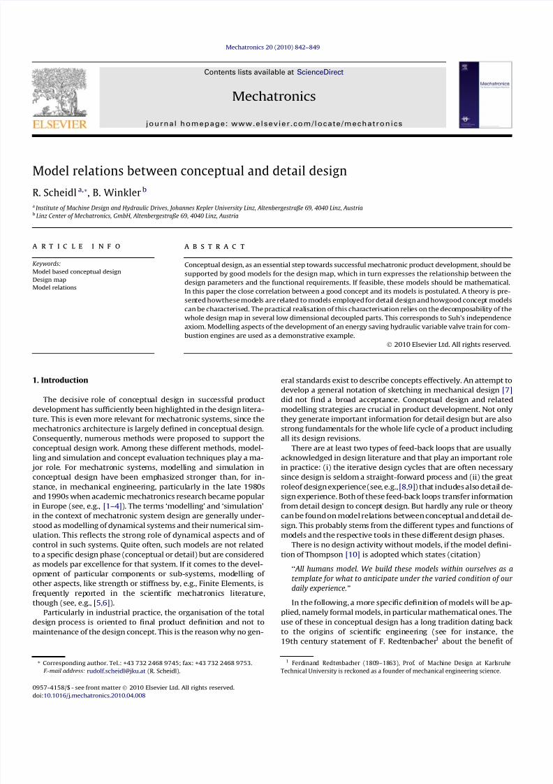
sign. Fig. 1 shows qualitatively, how the involved parameter spaces
DPconcept and DPdetail and the space of FRs are related to each other
by maps and how these maps are represented by manifolds or
graphs, respectively. On the left hand side of Fig. 1 parameter
spaces and FRs space are shown separately to indicate that these
spaces often have high dimension and that consequently the
DMs cannot be fully represented by graphs. On the right hand side
of Fig. 1 the DMs are sketched as manifolds in the product space
DPconcept FR.
Fig. 1. DMs of concept (DMconcept) and detail design (DMdetail) and their comparison. DMconcept maps from the space of the concept model parameters DP concept with its co-ordinates DPconcept,1, DPconcept,2, . . . to the space of FR. DMdetail maps from the space of the detail model parameters DP detail with its co-ordinates DPdetail,1, DPdetail,2, . . . to FR.
844 R. Scheidl, B. Winkler / Mechatronics 20 (2010) 842–849

8/11/2019 2.Model Relations Between Conceptual and Detail Design
http://slidepdf.com/reader/full/2model-relations-between-conceptual-and-detail-design 4/8
DMconcept is a unique function of DPconcept. DMdetail,red is not a
function of DPconcept but is a projection of DMdetail into DPconcept
FR. That projection consists of two parts: the domain set DPdetail
of DMdetail or its subset DPdetail_feasible, respectively (its meaning is
explained below), are projected to the domain set of DPconcept by
U; the elements DMdetail(DPdetail_feasible) of the codomain set FR
are projected just by the identity map, since the codomain sets of
DMdetail and DMconcept in the context of this comparison are the
same FRs.
DMconcept makes useful predictions, if technically feasible com-
binations of DPdetail, named DPdetail_feasible, can be found which pro-
vide roughly the same FRs as DMconcept does for the corresponding
values of DPconcept = U(DPdetail_feasible). Additionally,U shouldnot be
very sensitive to variations d(DPdetail) in the subspace DPdetail_feasible,
otherwise, even a DMconcept that is robust itself (meaning low sen-
sitivity of the FR with respect to variations of DPconcept) would notbe realised robustly on the detail design level. This is not a usual
robustnesscriterion but refers to the robustnessof theconcept with
respect to the detail design as stated at the end of Section 2.
Fig. 1 also indicates that DMconcept may have a limited validity
range. If FRscannotbe fulfilledby anytechnicallyfeasible detail real-
isation of a concept this concept must be replaced by another one.
Clearly, in many practical design problems such maps are much
more complex and graphical representations as in Fig. 1 are not al-
ways possible. However, if the DM fulfils Suh’s independence ax-
iom, graphical representations according to Fig. 1 are easily
possible. But, comprehension of the DM is also possible with a less
strict decoupling than Suh’s axiom asks for. In this context a more
general formulation of that axiom could read: Concepts are to be
preferred whose DM can be decomposed in a set of fairly simple
uncoupled maps (say, each involving 3 DPs maximum).
4. Example hydraulic variable valve train
The development of a hydraulic variable valve train (VVT) for
combustion engines is taken as an example to elucidate the theo-
retical statements of the last section. An overview about variable
valve timing can be found in [22]. A VVT based on an energy saving
hydraulic spring concept has been developed by the authors’ re-
search group [23–25]. For the purpose mentioned above it suffices
to take the first development period leading to a first simple proto-
type. The two main FRs on the VVT are:
FR1: Realisation of a certain maximum stroke xmax of the enginevalves’ opening/closing motion.
FR2: Realisation of a certain switching time t sw in which that
engine valve opens and closes.
5. Concept design model
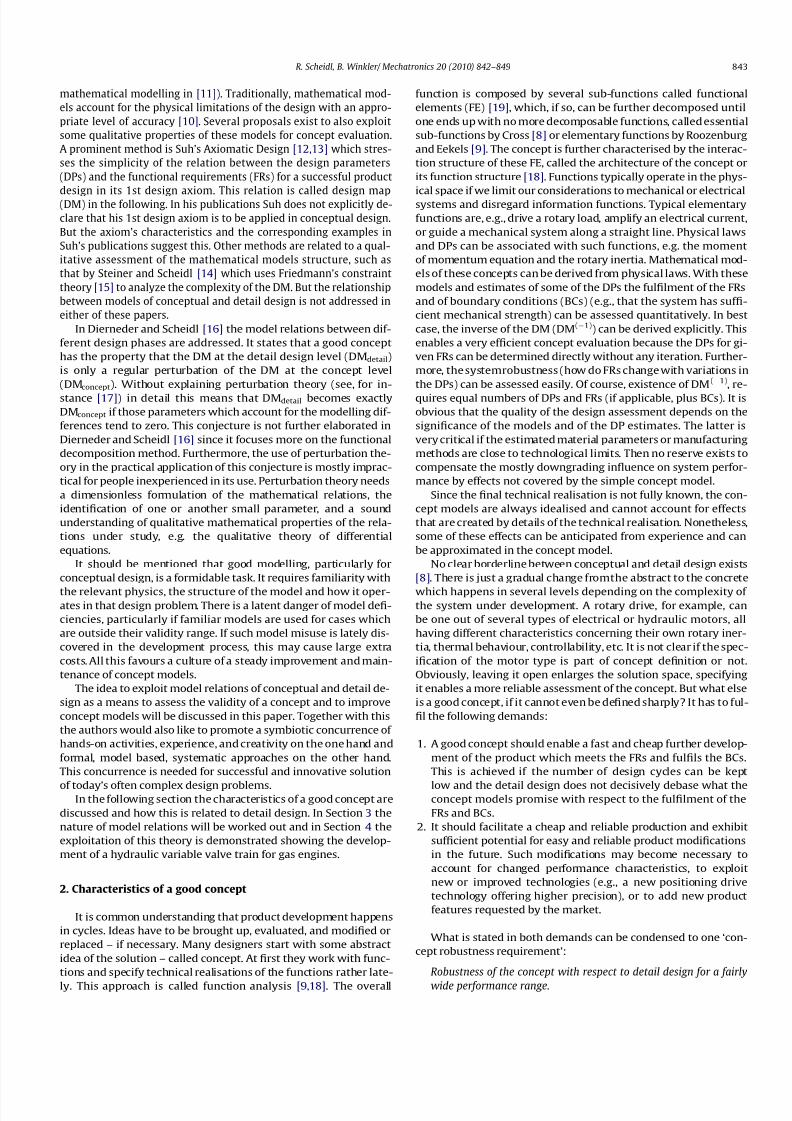
The basic idea of this VVT concept which is shown in Fig. 3 by
its hydraulic circuit is to use the fluid fill cavities V1 and V2 (of size
V 1 and V 2, respectively) in combination with the fluid compress-
ibility, quantified by its compression modulus E oil, as a hydraulic
spring. The system constitutes a mechanical oscillator with the
mass m of the piston plus the attached engine valve and two
springs realised by fluid compressibility in V1 and V2. The 2/2
way valve Va1 is a latch that holds the oscillator in its end posi-
tions. At closed engine valve position ( x = 0) V1 and V2 have sys-
tem pressure pS . When Va1 is opened the net hydraulic force on
the piston is positive since then the two cylinder pressures p1, p2
equal the system pressure pS and the piston area A1 is larger than
the rod side area A2. Hence, the piston is accelerated. When the
piston moves in outward direction the pressure in V2 increases
and decreases in V1. After some time the hydraulic force reverses
and, finally, the piston speed _ x becomes zero; the piston has per-
formed a half oscillation. At that moment the valve Va1 is closed
to hold the engine valve in the open position. Opening Va1 once
more for a half oscillation period lets the piston swing back to
its initial position. Of course, that is an idealised model. It neglects
mechanical or hydraulic losses, hydraulic fluid compressibility in
the cylinder chamber and in case of an engine outlet valve the con-
siderable combustion gas pressure. Since fluid has to flow through
the system’s main valve Va1 that valve must be of sufficient
nominal flow rate to create only negligible pressure losses and,furthermore, must be switching much faster than the intended
switching time t sw of the engine valve. Also measures must be
taken to bring the system in its initial state and to compensate
for losses which cannot be totally avoided. This is accomplished
by the two valves Va1 and Va3.
In a simple mathematical model the idealised concept for the
engine inlet valve VVT is composed of
1. The momentum equation for the motion x(t ) of the piston with
the attached engine valve
m€ x ¼ p1 A1 p2 A2 ð3Þ
2. The compressibility relations which provide the relations forthe two pressures (see, e.g. [26])
Fig. 2. Sketches of different beam models; (a) Euler–Bernoulli model of a cantilever beam requires only bending stiffness EI , length l, and load F as model parameters; (b) the
realisation of a beam as a thin walled structure may cause local deflections which can, for instance, be evaluated by a Finite Element (FE) model employing shell elements.
R. Scheidl, B. Winkler/ Mechatronics 20 (2010) 842–849 845
8/11/2019 2.Model Relations Between Conceptual and Detail Design
http://slidepdf.com/reader/full/2model-relations-between-conceptual-and-detail-design 5/8
p1 ¼ pS E oil xA1
V 1; p2 ¼ pS þ E oil
xA2
V 2ð4Þ
p1 and p2 are the pressures in the two cylinder chambers and pS is
the system pressure (see Fig. 3). If Eq. (4) is inserted in Eq. (3) a
mechanical oscillator equation results
m
d2 x
dt 2 þ
E oil A21
V 1 þ
E oil A22
V 2 !
x ¼ pS ð A1 A2Þ ð5Þ
From its solution which is a sinusoidal curve for x(t ) the two
performance values stroke xmax and switching time t sw can be de-
rived easily
xmax ¼ 2 pS
E oil
A1 A2
A21
V 1þ
A22
V 2
ð6Þ
t sw ¼ p
ffiffiffiffiffiffiffiffiffiffiffiffiffiffiffiffiffiffiffiffiffiffiffiffiffiffim
E oil A2
1
V 1þ
A22
V 2
v uut ð7Þ
Eqs. (6) and (7) describe the DM of this simple concept model
with its five DPs: pS , A1, A2, V 1, V 2. Such compact analytical results
can be interpreted directly without a graphical visualization. Evenin this simple case a graphical representation of the DM would not
be possible because of the dimensionality of the DM. From a design
viewpoint the inverse of DM is needed, since the DP have to be
found which fulfil the FRs.
The compression modulus E oil of the hydraulic fluid is a material
parameter that cannot be changed, hence is not considered a DP
here. Also the mass m of the system is not a DP since the engine
valve is a given part and the hydraulic piston which contributes
to m is mainly determined by the stroke xmax and the two piston
areas A1 and A2.
There are some technical constraints (BCs in the sense of Suh
[12]) which limit the free choice of all five DPs.
BC 1: The hydraulic system pressure pS is limited by available
hydraulic components, like pumps and valves.
BC 2: The maximum value p2,max of the pressure p2 should not
exceed some limit values if usual hydraulic oil is used since
compressibility decreases and viscosity increases significantly
if pressures go beyond 700 bar.
These two constraints and the two FRs leave one degree of free-
dom for optimization, for instance, to minimize the maximum flow
rate through Va1. This is motivated by the fact that development
and realisation of fast switching valves with a high nominal flow
rate are challenging tasks and larger valves have a tendency to re-
quire more actuation power and space. The maximum flow rate
over Va1 is
Q max;Va1 ¼ A1p x
max2t sw
ð8Þ
Thus, minimization of Q max,Va1 requires minimization of piston
area A1 for which the following relation can be derived
A1 ¼mp2 xmaxð pS þ p2;maxÞ
2 pS t 2swð p2;max p1;minÞ
ð9Þ
Eq. (9) states that p2,max should be maximized and p1,min mini-
mized by going to the respective technical limits which have been
discussed above for p2,max. A lower limit for p1,min is avoidance of
outgassing of air. With these relations explicit formulas for all
DPs of the concept can be derived, shown in Eq. (10) for the
remaining DPs.
A2 ¼ A1
pS þ p1;min
pS þ p2;max
; V 1 ¼ A1 xmax
E oil pS p1;min
;
V 2 ¼ V 1 p2
S p21;min
p22;max p2
S
ð10Þ
6. Detail design model
The real performance is influenced by several effects that were
neglected in the concept model and that depend on detail designfeatures:
pressure loss in the Va1; the associated parameter is the nom-
inal flow rate Q N ,Va1,
the finite switching time t sw,Va1 of Va1 (the time needed to
switch from off to fully on or vice versa) and t on,Va1 (the time
the controller commands Va1 to be switched on),
friction and leakage between piston and cylinder; associated
parameters are the clearance h gap and length l gap of the sealing
gap between piston and cylinder and the oil viscosity moil,
compressibility of the fluid in the cylinder; the associated
parameters are the initial volume V c 10, when the engine valve
is closed and the piston is in its initial position ( x = 0), and the
oil compression modulus E oil.
Of course, the set of DPs in this model is much largerthan of the
concept model.
A model was set-up in Matlab/Simulink – shown by its sche-
matic in Fig. 4 – which includes these additional effects and allows
studying the role of the DPdetail. In the sense of the design attitude
mentioned in Section 2 and the modelling relations of Section 3 the
simulation study has to show if technically feasible DPdetail combi-
nations of this extended model can be found which realize the
DMconcept.
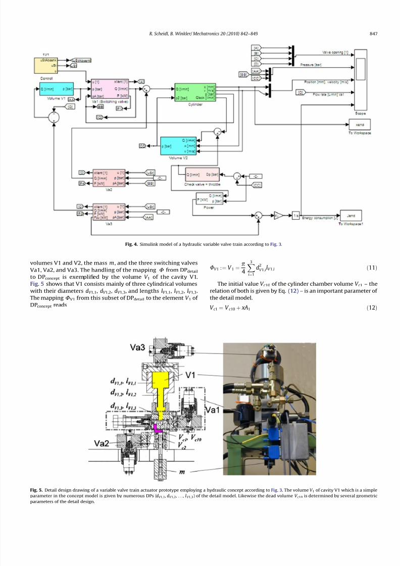
The detail mechanical design is shown in Fig. 5 by the assembly
drawing and a photo of the test-rig. All components of this system
according to the schematic of Fig. 3 are shown: the hydraulic actu-
ation cylinder with its two chambers (having actual volumes V C 1and V C 2; V C 10 is the initial value of V C 1), the two hydraulic spring
Fig. 3. Concept of an energy efficient hydraulic variable valve timing actuator and typical latching valve Va1 operation and engine valve motion x(t ): full line: motion of the
concept model; dashed line: motion of the numerical model.
846 R. Scheidl, B. Winkler / Mechatronics 20 (2010) 842–849
8/11/2019 2.Model Relations Between Conceptual and Detail Design
http://slidepdf.com/reader/full/2model-relations-between-conceptual-and-detail-design 6/8
volumes V1 and V2, the mass m , and the three switching valves
Va1, Va2, and Va3. The handling of the mapping U from DPdetail
to DPconcept is exemplified by the volume V 1 of the cavity V1.
Fig. 5 shows that V1 consists mainly of three cylindrical volumes
with their diameters dV 1,1, dV 1,2, dV 1,3, and lengths lV 1,1, lV 1,2, lV 1,3.
The mapping UV1 from this subset of DPdetail to the element V 1 of DPconcept reads
UV 1 :¼ V 1 ¼ p
4
X3
i¼1
d2V 1;ilV 1;i ð11Þ
The initial value V c 10 of the cylinder chamber volume V c 1 – the
relation of both is given by Eq. (12) – is an important parameter of
the detail model.
V c 1 ¼ V c 10 þ xA1 ð12Þ
Fig. 4. Simulink model of a hydraulic variable valve train according to Fig. 3.
Fig. 5. Detail design drawing of a variable valve train actuator prototype employing a hydraulic concept according to Fig. 3. The volume V 1 of cavity V1 which is a simple
parameter in the concept model is given by numerous DPs (dV 1,1, dV 1,2, . . ., l V 1,3) of the detail model. Likewise the dead volume V c 10 is determined by several geometricparameters of the detail design.
R. Scheidl, B. Winkler/ Mechatronics 20 (2010) 842–849 847

8/11/2019 2.Model Relations Between Conceptual and Detail Design
http://slidepdf.com/reader/full/2model-relations-between-conceptual-and-detail-design 7/8
The compressibility related to V c 1 causes losses and an oscillat-
ing motion of the piston when valve Va1 is closed after the opening
motion (see dashed line of motion diagram in Fig. 3). Since these
effects were ignored in the concept design model, V c 10 plays only
a trivial role in the mappingU. This can be expressed in the follow-
ing mathematical form
DPconcept ¼
U
ðDP
detail Þ ~U
ðDP
detail;reducedÞ;
V C 1 R DPdetail;reduced ð13Þ
V c 10 is not an explicit parameter of the final detail design but an
intermediate modelling related parameter. This volume, shown as
coloured area in Fig. 5, is determined by several dimensions of the
mechanical design of the valve block of Va1 and of a connecting
plate. Thus, even this refined Simulink model – like most models –
uses a reduced parameter set that is linked to the detail design data
by some mapping. Other examples of intermediate parameters are
the switching time t sw,Va1 and the nominal flow rate Q Va1 of the
valve Va1. They depend on several mechanical and solenoid detail
parameters of Va1. If such a valve or its main components are
purchased from some vendor, the parameters t sw,Va1 and Q Va1
would be specified requirements.
The whole mapping U reads
pS
A1
A2
V 1
V 2
0BBBBBB@
1CCCCCCA
¼
pS
D2p=4
ðD2 d2
Þp=4
UV 1ðdV 1; dV 2; dV 3; lV 1; lV 2; lV 3Þ
UV 2ð. . .Þ
0BBBBBB@
1CCCCCCA
ð14Þ
UV 1 is given in Eq. (11), UV 2 is quite similar to UV 1 and not
explicitly stated here since not all relevant dimensions of the detail
design can be seen in Fig. 5. The many parameters of the detailed
model which have no effects in the concept model (like Q Va1, t sw,
V C 10) are not explicitly shown in Eq. (14). They play the same role
like y in the map ( x, y)?
f ( x, y) = x
2
.
In the context of concept model evaluation this numerical model
has to answer the question how much the additional effects of
DMdetail deteriorate DMconcept (Eqs. (6) and (7)). A general graphical
visualization according to Fig. 1 cannot be given due to the dimen-
sionality of these maps. In Section 4.1 DMconcept was augmented by
BCs and an optimization criterion to derive an inverse DM from the
two FRs to DPconcept. This approach can be exploited here to give a
graphically visualized answer to the posted question. Fig. 6 shows
in which way the A1 coordinate of the inverse of DMconcept – called
DMconcept(1)
A1 – is perturbed by thecorresponding inverseDMdetail –
namedDMdetail(1)
A1 – if thethreeadditionalDPs:valve nominal flow
rate Q Va1, switching time t sw,Va1, and dead volume V c 10 are varied in
the following intervals
Q Va1 2 12Q max;Va1 3
2Q max;Va1
t sw;Va1 2 1
2 3
2
max 0:5 ms; Q Va1
50 l=min ms
V c 10 2 ½2 50:0006 ðQ Va1 min=lÞ
1:5
ð15Þ
Q max ,Va1 is the maximum flow rate through Va1. The achievable
switching time and the dead volume V C 10 depend on the valve size.
The corresponding rules of Eq. (15) have been found as an estimate
for a piloted spool valve and how closely it can be connected to thehydraulic cylinder. Note, that the diagram in Fig. 6 does not show
these parameters. The coordinate switching time t sw is the
achieved switching time of the engine valve which may signifi-
cantly exceed the switching time t on,Va1 commanded by the con-
troller (block ‘Control’ in the Simulink model, see Fig. 4) if t sw,Va1
is relatively large.
Fig. 6 shows DMdetail(1)
A1 and DMconcept(1)
A1. DMdetail(1)
A1 – or
correctly, its projection to DMconcept(1) – is approximately repre-
sented by individual points (graphically visualized by small spheres
in thefigure) andthe complex hull of these points. DMconcept(1)
A1 is
given by the curved meshed surface. DMconcept(1)
A1 is actually
covered by DMdetail(1)
A1 in a wide range. This is the validity range
of the concept model. There, detail parameter combinations can be
found whichrealize the desired systemperformancein terms of the
Fig. 6. Part of the inverse of the DMs of the concept model (curved surface: DM concept(1)
A1) and of the detail model (small spheres and triangular surfaces, respectively:
DMdetail(1)
A1); these DMs map fromthe space of the two FRs: FR 1 = t sw andFR 2 = xmax tothe DP space of the concept model; only the A1 component (piston area) of this mapis
shown; rectangle and dashed line at base area show the projection of the DMconcept(
1)A1 and DMdetail(
1)A1, respectively. The dashed area constitutes the validity range of DMconcept
(1)A1 projected to the FR space.
848 R. Scheidl, B. Winkler / Mechatronics 20 (2010) 842–849

8/11/2019 2.Model Relations Between Conceptual and Detail Design
http://slidepdf.com/reader/full/2model-relations-between-conceptual-and-detail-design 8/8
two FRs: t sw and xmax, in other words, DMconcept is robust there with
respect to the detail design. The validity range ends where the con-
vex hull intersects DMconcept(1)
A1. The projection of this validity
range on the FR space is shown by the dashed area.
7. Summary and conclusion
Good conceptual design is a prerequisite for a successful prod-uct development. For that the sound understanding of the DM,
i.e. the mapping from the space of the DPs to the space of FRs is
essential. Good, i.e., simple but fairly accurate mathematical mod-
els of the DM are extremely helpful. Since product development
typically envisages a wider range of final product realisations the
knowledge of the validity range of these models is important for
a successful systematic design.
In this paper a strong linkage of concept andconcept models, i.e.
models DMconcept which map the DMconcept of the concept into the
space of FRs, is postulated. The comparison of refined models DMde-
tail used in detail design with concept models can be made by a
mappingU fromthe space of DPs of the detailedmodel to the space
of the DPs of the concept model and comparing the DMdetail of the
detailed models with the DMconcept
of the concept model applied.
That comparison can also be done by means of the inverses of these
two DM. The implications and usage of this approach was exempli-
fied by a variable valve train for engine valves.
The practical analysis of these model relations can only work if
the DM or its inverse DM(1) can be decomposed in a set of uncou-
pled maps with a small number of DPs each. This simplicity
requirement corresponds to Suh’s 1st design axiom. In view of
his theory concept designers are always requested to evaluate
the appropriateness of the FRs that are imposed on a certain de-
sign, since modifications of these FRs can have impact on the com-
plexity of the DM. Suh’s corollary #2 [12] – minimize the number
of FRs – directly expresses this. Sometimes even small changes in
the concrete definition of the FRs can make the DM simpler. In
the example of the variable valve train in Section 4 this rule has
been observed by posing only two FRs.
Developing powerful models for conceptual design is a field of
high practical relevance. Currently model based design is a strong
trend. The authors are convinced that the success of this trend re-
lies on efficient concept models, much more than on the advance-
ment of models for the detail design.
Acknowledgements
The authors appreciate the reviewers’ comments and recom-
mendations for improvement which made this paper much more
understandable.
This work was sponsored by the Austrian Center of Competence
in Mechatronics (ACCM) which is a COMET K2 center and is funded
by the Austrian Federal Government, the Federal State Upper Aus-tria, and its Scientific Partners.
References
[1] Bracewell RH, Chaplin RV, Bradley DA. Schemebuilder and layout: computer
based tools to aid the design of mechatronic systems. In: Mechatronics – the
integration of engineering design. The Institution of Mechanical Engineers;
1992. p. 1–6.
[2] Gawthrop PJ. Design of mechatronic systems using bond graphs. In:
Mechatronics – the integration of engineering design. The Institution of
mechanical Engineers; 1992. p. 15–21.
[3] Gawthrop PJ. Bond graphs: a representation of mechatronic systems.Mechatronics 1991;1:127–56.
[4] Ju MS, Hsu CJ. Automatic modeling of mechatronic systems via symbolic
approach. Mechatronics 1991;1:157–74.
[5] Dargahia J, Sedaghatia R, Singha H, Najarianb S. Modeling and testing of an
endoscopic piezoelectric-based tactile sensor. Mechatronics 2007;17:
462–7.
[6] Lia J, Sedaghatia R, Dargahia J, Waechter D. Design and development of a new
piezoelectric linear inchworm actuator. Mechatronics 2005;15:651–81.
[7] Breeing A. Die Prinzipskizze als Ausgangsdokument der Konzeptphase. In:
Proceedings of the international conference on engineering design (ICED’91),
Zürich, Switzerland; 1991.
[8] Cross N. Engineering design methods. 2nd ed. Chichester: Wiley; 1989.
[9] Roozenburg NFM, Eekels J. Product design: fundamentals and
methods. Chichester: Wiley; 1991.
[10] Thompson DE. Design analysis, mathematical modeling of nonlinear
systems. Cambridge: Cambridge University Press; 1999.
[11] Buchheim G, Sonnemann R. Lebensbilder von Ingenieurwissenschaftlern.
Basel: Birkhäuser; 1989.
[12] Suh NP. Principles of design. New York, Oxford: Oxford University Press; 1990.[13] Suh NP. Axiomatic design, advances and applications. New York,
Oxford: Oxford University Press; 2001.
[14] Steiner B, Scheidl R. Computer aided conceptual design, a concept study of fast
hydraulic 2/2 way seat valves. In: Proceedings 4th FPNI-PhD symposium,
Sarasota, Florida; 2006. p. 409–20.
[15] Friedmann JF. Constraint theory, multidimensional mathematical model
management. IFRS international series on systems science and engineering,
vol. 23. New York: Springer; 2005.
[16] Dierneder S, Scheidl R. Conceptual design, functional decomposition,
mathematical modelling, and perturbation analysis. In: Pichler F, Moreno-
Diaz R, Kopacek P, editors. Springer lecture notes in computer science
1798. Vienna: Springer; 1999.
[17] Nayfeh AH. Introduction to perturbation techniques. Hoboken (NJ): Wiley;
1993.
[18] Pahl G, Beitz W. Konstruktionslehre: Handbuch für Studium und Praxis. 2nd
ed. Berlin: Springer; 1986.
[19] Scheidl R, Dierneder S, Mörwald K. Computer aided conceptual design by a
functional decomposition method for process oriented heavy machinery and
its relation to mechatronization. In: Bradshaw A, Counsell J, editors. Lancaster
international workshop on engineering design – computer aided conceptual
design. Lancaster: Lancaster University; 1998.
[20] Ziegler F. Mechanics of solids and fluids. New York – Vienna: Springer-Verlag;
1991.
[21] Young WC. Roark’s formulas for stress and strain. 6th ed. New York: McGraw-
Hill; 2002.
[22] Pischinger S, editor. Variable Ventilsteuerung. Essen: Expert-Verlag; 2002.
[23] Krimbacher N. Development, conceptual design and experimental verification
of a novel switching type hydraulic actuator for energy saving fast positioning.
PhD thesis, Johannes Kepler University Linz; November 2002.
[24] Plöckinger A, Krimbacher N, Scheidl R. A hydraulic energy efficient fast
positioning actuator exploiting a hydraulic spring concept. In: Proc 8th
Scandinavian int conf on fluid power, Tampere, Finland; 2003. p.
1187–201.
[25] Plöckinger A. Comparison of three different concepts for a variable valvetrain
for huge combustion engines. In: Proc 3rd FPNI PhD symposium, Terassa,
Spain; 2004. p. 453–62.
[26] Merrit H. Hydraulic control systems. New Jersey: Wiley; 1991.
R. Scheidl, B. Winkler/ Mechatronics 20 (2010) 842–849 849