Embed Size (px)
Citation preview
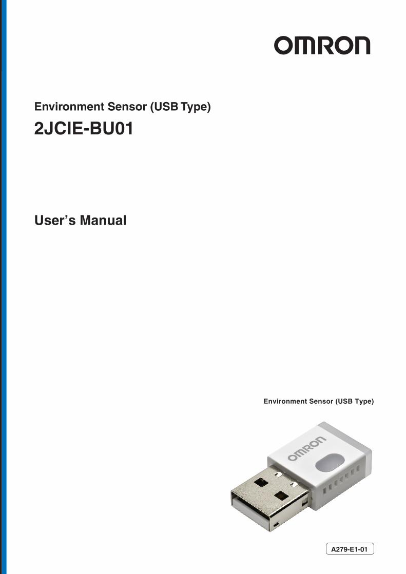
Environment Sensor (USB Type)
Environment Sensor (USB Type)
User’s Manual
A279-E1-01
2JCIE-BU01

2JCIE-BU01 Environment Sensor (USB Type) User's Manual (A279) 1
Table of Contents
1. Introduction ............................................................................................................................... 4
Scope ................................................................................................................................... 4 1.1. Communication interface ......................................................................................................... 4 1.2. Operation mode ..................................................................................................................... 5 1.3.
1.3.1 Normal mode ................................................................................................................. 5 1.3.2 Acceleration logger mode ............................................................................................... 5
Use case ............................................................................................................................... 6 1.4.1.4.1 BLE connection .............................................................................................................. 6 1.4.2 Receive advertising data (BLE non-connection) .............................................................. 6 1.4.3 USB communication ....................................................................................................... 6
2. BLE GATT Services ..................................................................................................................... 7 Memory Data Service (Service UUID: 0x5000) .............................................................................. 8 2.1.
2.1.1 Memory index information (Characteristics UUID: 0x5004) .......................................... 10 2.1.2 Request memory index (Characteristics UUID: 0x5005) ............................................... 11 2.1.3 Memory status (Characteristics UUID: 0x5006) ............................................................ 12 2.1.4 Memory sensing data (Characteristics UUID: 0x500A) .................................................. 14 2.1.5 Memory calculation data (Characteristics UUID: 0x500B) ............................................. 14 2.1.6 Memory sensing flag (Characteristics UUID: 0x500C) ................................................... 15 2.1.7 Memory calculation flag (Characteristics UUID: 0x500D) .............................................. 15
Latest Data Service (Service UUID: 0x5010) ............................................................................... 16 2.2.2.2.1 Latest sensing data (Characteristics UUID: 0x5012) ..................................................... 18 2.2.2 Latest calculation data (Characteristics UUID: 0x5013) ................................................ 18 2.2.3 Latest sensing flag (Characteristics UUID: 0x5014) ...................................................... 19 2.2.4 Latest calculation flag (Characteristics UUID: 0x5015) ................................................. 19 2.2.5 Latest acceleration status (Characteristics UUID: 0x5016) ........................................... 20
Acceleration Service (Service UUID: 0x5030) ............................................................................. 21 2.3.2.3.1 Vibration count (Characteristics UUID: 0x5031) ........................................................... 25 2.3.2 Request acceleration memory index (Characteristics UUID: 0x5032) ............................ 26 2.3.3 Acceleration memory status (Characteristics UUID: 0x5033) ........................................ 27 2.3.4 Acceleration memory data [Header] (Characteristics UUID: 0x5034) ............................ 28 2.3.5 Acceleration memory data [Data] (Characteristics UUID: 0x5034) ............................... 30
Control Service (Service UUID: 0x5110) .................................................................................... 33 2.4.2.4.1 LED setting [normal state] (Characteristics UUID: 0x5111) .......................................... 34 2.4.2 LED setting [event state] (Characteristics UUID: 0x5112) ............................................ 35 2.4.3 LED state [operation] (Characteristics UUID: 0x5113).................................................. 36 2.4.4 Installation offset (Characteristics UUID: 0x5114) ....................................................... 37 2.4.5 Advertise setting (Characteristics UUID: 0x5115)......................................................... 38 2.4.6 Memory reset (Characteristics UUID: 0x5116) ............................................................. 39 2.4.7 Mode change (Characteristics UUID: 0x5117) .............................................................. 39 2.4.8 Acceleration logger control (Characteristics UUID: 0x5118) ......................................... 40 2.4.9 Acceleration logger status (Characteristics UUID: 0x5119) ........................................... 42
Time Setting Service (Service UUID: 0x5200) ............................................................................. 43 2.5.2.5.1 Latest time counter (Characteristics UUID: 0x5201) ..................................................... 44 2.5.2 Time setting (Characteristics UUID: 0x5202) ............................................................... 44

2JCIE-BU01 Environment Sensor (USB Type) User's Manual (A279) 2
2.5.3 Memory storage interval (Characteristics UUID: 0x5203) ............................................. 45 Event Setting Service (Service UUID: 0x5210) ............................................................................ 46 2.6.
2.6.1 Event pattern [Sensor 1] .............................................................................................. 47 2.6.2 Event pattern [Sensor 2] .............................................................................................. 48 2.6.3 Event pattern [Acceleration] ........................................................................................ 48
Information Service (Service UUID: 0x5400) .............................................................................. 49 2.7.2.7.1 Error status (Characteristics UUID: 0x5401) ................................................................ 50 2.7.2 Mounting orientation (Characteristics UUID: 0x5402) .................................................. 51 2.7.3 FLASH memory status (Characteristics UUID: 0x5403) ................................................. 52
Generic Access Service (Service UUID: 0x1800)......................................................................... 53 2.8.2.8.1 Device name (Characteristics UUID: 0x2A00) ............................................................... 54 2.8.2 Appearance (Characteristics UUID: 0x2A01) ................................................................ 54 2.8.3 Peripheral preferred connection parameters (Characteristics UUID: 0x2A04) ............... 54 2.8.4 Central address resolution (Characteristics UUID: 0x2AA6) .......................................... 55
Device Information Service (Service UUID: 0x180A) .................................................................... 56 2.9.2.9.1 Model number string (Characteristics UUID: 0x2A24) .................................................. 57 2.9.2 Serial number string (Characteristics UUID: 0x2A25) ................................................... 57 2.9.3 Firmware revision string (Characteristics UUID: 0x2A26) ............................................. 58 2.9.4 Hardware revision string (Characteristics UUID: 0x2A27) ............................................ 58 2.9.5 Manufacturer name string (Characteristics UUID: 0x2A28) .......................................... 58
3. BLE Advertising packet ............................................................................................................. 59 Sensor data ......................................................................................................................... 60 3.1. Calculation data ................................................................................................................... 61 3.2. Sensor data & Calculation data (Scan rsp) ................................................................................ 62 3.3. Sensor flag & Calculation flag (Scan rsp) .................................................................................. 64 3.4. Serial number ...................................................................................................................... 66 3.5.
4. USB Communication ................................................................................................................. 67 Communication specification ................................................................................................. 67 4.1. Communication procedure ..................................................................................................... 67 4.2. Frame format ....................................................................................................................... 68 4.3.
4.3.1 Common frame format ................................................................................................. 68 4.3.2 CRC-16 calculation ....................................................................................................... 68 4.3.3 Payload frame format [Command from Host-Controller]............................................... 69 4.3.4 Payload frame format [Normal Response from 2JCIE-BU01] ........................................ 70 4.3.5 Payload frame format [Error Response from 2JCIE-BU01] ............................................ 71
USB original address ............................................................................................................ 72 4.4.4.4.1 Memory data long (Address: 0x500E) .......................................................................... 73 4.4.2 Memory data short (Address: 0x500F) ......................................................................... 75 4.4.3 Latest data Long (Address: 0x5021) ............................................................................ 76 4.4.4 Latest data short (Address: 0x5022) ............................................................................ 77 4.4.5 Acceleration memory data [Header] (Address: 0x503E) ............................................... 78 4.4.6 Acceleration memory data [Data] (Address: 0x503F) ................................................... 80
BLE common address ........................................................................................................... 82 4.5.4.5.1 Latest memory information (Address: 0x5004) ............................................................ 85 4.5.2 Latest sensing data (Address: 0x5012) ........................................................................ 85 4.5.3 Latest calculation data (Address: 0x5013) ................................................................... 86 4.5.4 Latest sensing flag (Address: 0x5014) ......................................................................... 86

2JCIE-BU01 Environment Sensor (USB Type) User's Manual (A279) 3
4.5.5 Latest calculation flag (Address: 0x5015) ..................................................................... 87 4.5.6 Latest acceleration status (Address: 0x5016) ............................................................... 87 4.5.7 Vibration count (Address: 0x5031) .............................................................................. 88 4.5.8 LED setting [normal state] (Address: 0x5111) ............................................................. 88 4.5.9 LED setting [event state] (Address: 0x5112) ................................................................ 89 4.5.10 LED setting [operation] (Address: 0x5113) ................................................................ 89 4.5.11 Installation offset (Address: 0x5114) ......................................................................... 90 4.5.12 Advertise setting (Address: 0x5115) .......................................................................... 91 4.5.13 Memory reset (Address: 0x5116) ............................................................................... 91 4.5.14 Mode change (Address: 0x5117) ................................................................................ 92 4.5.15 Acceleration logger control (Address: 0x5118) ........................................................... 92 4.5.16 Acceleration logger status (Address: 0x5119) ............................................................ 93 4.5.17 Latest time counter (Address: 0x5201) ...................................................................... 93 4.5.18 Time setting (Address: 0x5202) ................................................................................. 93 4.5.19 Memory storage interval (Address: 0x5203) ............................................................... 94 4.5.20 Event pattern [Sensor 1] (Address: 0x5211 etc.) ....................................................... 94 4.5.21 Event pattern [Sensor 2] (Address: 0x5212 etc.) ....................................................... 95 4.5.22 Event pattern [Acceleration] (Address: 0x5226 etc.) .................................................. 96 4.5.23 Error status (Address: 0x5401) .................................................................................. 97 4.5.24 Mounting orientation (Address: 0x5402) .................................................................... 98 4.5.25 Device information (Address: 0x180A) ....................................................................... 99
5. Data specification ................................................................................................................... 101 Output range ..................................................................................................................... 101 5.1. Event enable/disable ........................................................................................................... 103 5.2. Event flag.......................................................................................................................... 104 5.3.
5.3.1 Simple threshold ........................................................................................................ 105 5.3.2 Change threshold ....................................................................................................... 106 5.3.3 Average value threshold............................................................................................. 107 5.3.4 Peak to Peak threshold .............................................................................................. 108 5.3.5 Interval difference threshold ...................................................................................... 109 5.3.6 Base difference threshold ........................................................................................... 110
Event threshold.................................................................................................................. 111 5.4.
2JCIE-BU01 Environment Sensor (USB Type) User's Manual (A279) 4
1. Introduction
Scope 1.1.
This communication interface manual is applicable to the communication interface of the Environment Sensor USB Type (2JCIE-BU01).
Communication interface 1.2.
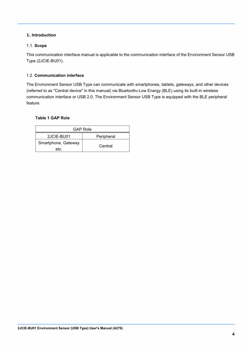
The Environment Sensor USB Type can communicate with smartphones, tablets, gateways, and other devices (referred to as "Central device" in this manual) via Bluetooth® Low Energy (BLE) using its built-in wireless communication interface or USB 2.0. The Environment Sensor USB Type is equipped with the BLE peripheral feature.
Table 1 GAP Role
GAP Role
2JCIE-BU01 Peripheral Smartphone, Gateway
etc. Central
2JCIE-BU01 Environment Sensor (USB Type) User's Manual (A279) 5
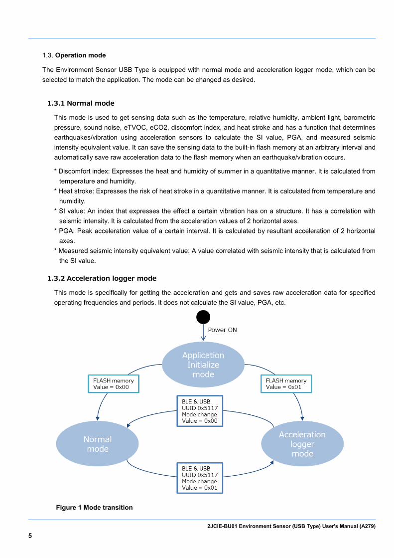
Operation mode 1.3.
The Environment Sensor USB Type is equipped with normal mode and acceleration logger mode, which can be selected to match the application. The mode can be changed as desired.
1.3.1 Normal mode
This mode is used to get sensing data such as the temperature, relative humidity, ambient light, barometric pressure, sound noise, eTVOC, eCO2, discomfort index, and heat stroke and has a function that determines earthquakes/vibration using acceleration sensors to calculate the SI value, PGA, and measured seismic intensity equivalent value. It can save the sensing data to the built-in flash memory at an arbitrary interval and automatically save raw acceleration data to the flash memory when an earthquake/vibration occurs. * Discomfort index: Expresses the heat and humidity of summer in a quantitative manner. It is calculated from
temperature and humidity. * Heat stroke: Expresses the risk of heat stroke in a quantitative manner. It is calculated from temperature and
humidity. * SI value: An index that expresses the effect a certain vibration has on a structure. It has a correlation with
seismic intensity. It is calculated from the acceleration values of 2 horizontal axes. * PGA: Peak acceleration value of a certain interval. It is calculated by resultant acceleration of 2 horizontal
axes. * Measured seismic intensity equivalent value: A value correlated with seismic intensity that is calculated from
the SI value.
1.3.2 Acceleration logger mode
This mode is specifically for getting the acceleration and gets and saves raw acceleration data for specified operating frequencies and periods. It does not calculate the SI value, PGA, etc.
Figure 1 Mode transition

2JCIE-BU01 Environment Sensor (USB Type) User's Manual (A279) 6
Use case 1.4.
This section describes representative use cases.
1.4.1 BLE connection
This case enables getting and saving sensing data, getting acceleration data when earthquakes occur, and configuring various settings such as LED lighting and mode switching by connecting with a central device via BLE communication. For details, refer to "2. BLE GATT Services."
Figure 2 BLE connection image
1.4.2 Receive advertising data (BLE non-connection)
This case uses the gateway on the other device and is suitable for applications such as collecting the data of multiple Environment Sensor USB Type. There are eight types of advertising packet, and sensing data acquisition, acceleration data acquisition, sensor event results, etc. can be selected. For details, refer to "3. Advertising packet."
Figure 3 BLE non-connection image
1.4.3 USB communication
This case enables getting and saving sensing data, getting acceleration data when earthquakes occur, and configuring various settings such as LED lighting and mode switching via USB communication. The basic commands are the same as with BLE communication. For details, refer to "4. USB communication."
Figure 4 USB communication image
2JCIE-BU01 Environment Sensor (USB Type) User's Manual (A279) 7
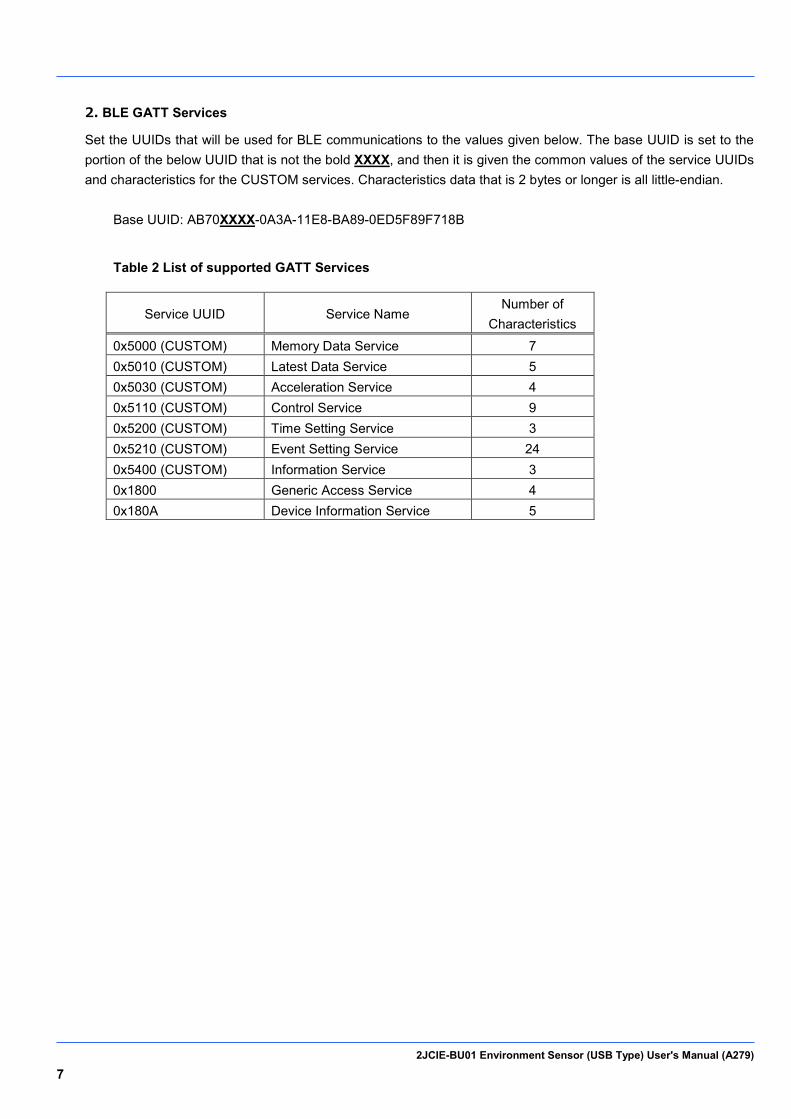
2. BLE GATT Services
Set the UUIDs that will be used for BLE communications to the values given below. The base UUID is set to the portion of the below UUID that is not the bold XXXX, and then it is given the common values of the service UUIDs and characteristics for the CUSTOM services. Characteristics data that is 2 bytes or longer is all little-endian.
Base UUID: AB70XXXX-0A3A-11E8-BA89-0ED5F89F718B
Table 2 List of supported GATT Services
Service UUID Service Name Number of
Characteristics 0x5000 (CUSTOM) Memory Data Service 7 0x5010 (CUSTOM) Latest Data Service 5 0x5030 (CUSTOM) Acceleration Service 4 0x5110 (CUSTOM) Control Service 9 0x5200 (CUSTOM) Time Setting Service 3 0x5210 (CUSTOM) Event Setting Service 24 0x5400 (CUSTOM) Information Service 3 0x1800 Generic Access Service 4 0x180A Device Information Service 5
2JCIE-BU01 Environment Sensor (USB Type) User's Manual (A279) 8
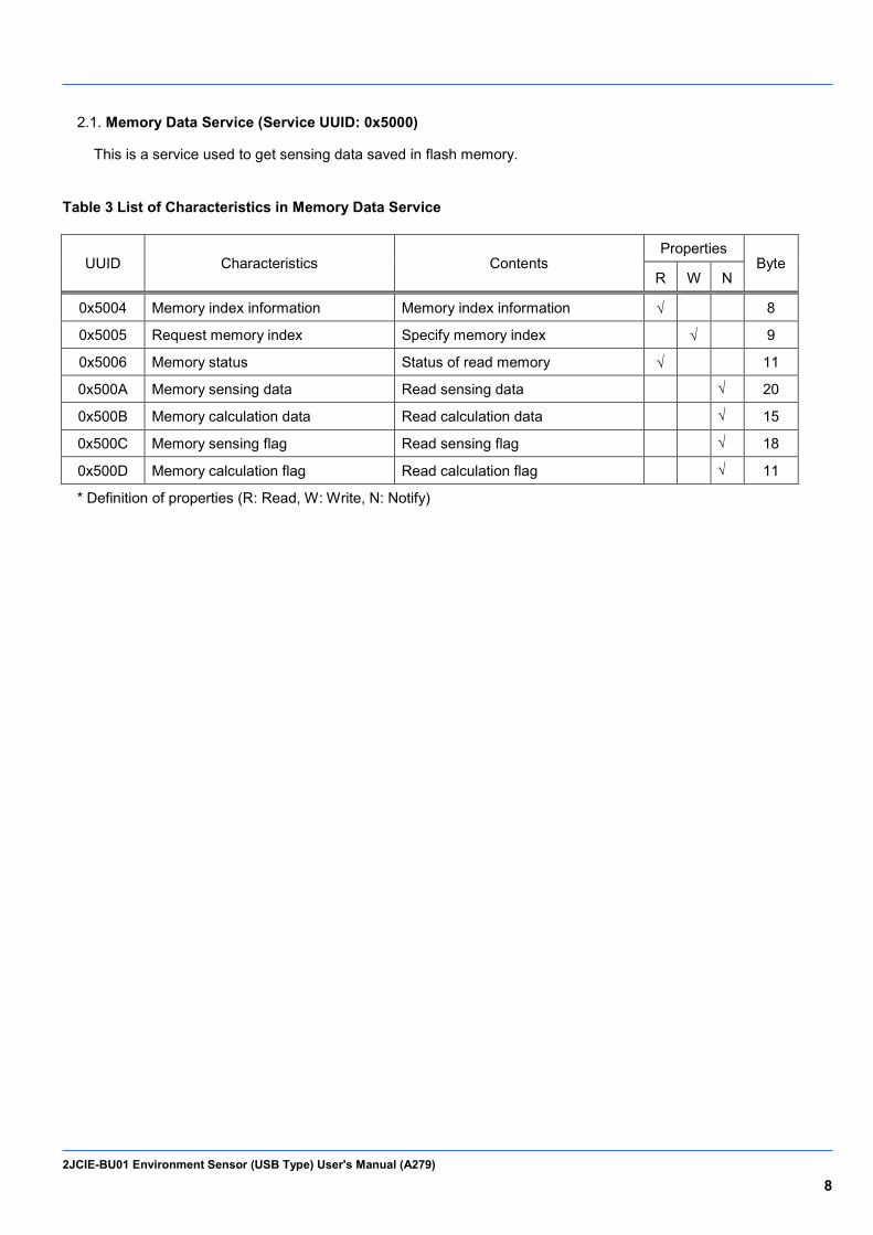
Memory Data Service (Service UUID: 0x5000) 2.1.
This is a service used to get sensing data saved in flash memory.
Table 3 List of Characteristics in Memory Data Service
UUID Characteristics Contents Properties
Byte R W N
0x5004 Memory index information Memory index information √ 8
0x5005 Request memory index Specify memory index √ 9
0x5006 Memory status Status of read memory √ 11
0x500A Memory sensing data Read sensing data √ 20
0x500B Memory calculation data Read calculation data √ 15
0x500C Memory sensing flag Read sensing flag √ 18
0x500D Memory calculation flag Read calculation flag √ 11
* Definition of properties (R: Read, W: Write, N: Notify)
2JCIE-BU01 Environment Sensor (USB Type) User's Manual (A279) 9
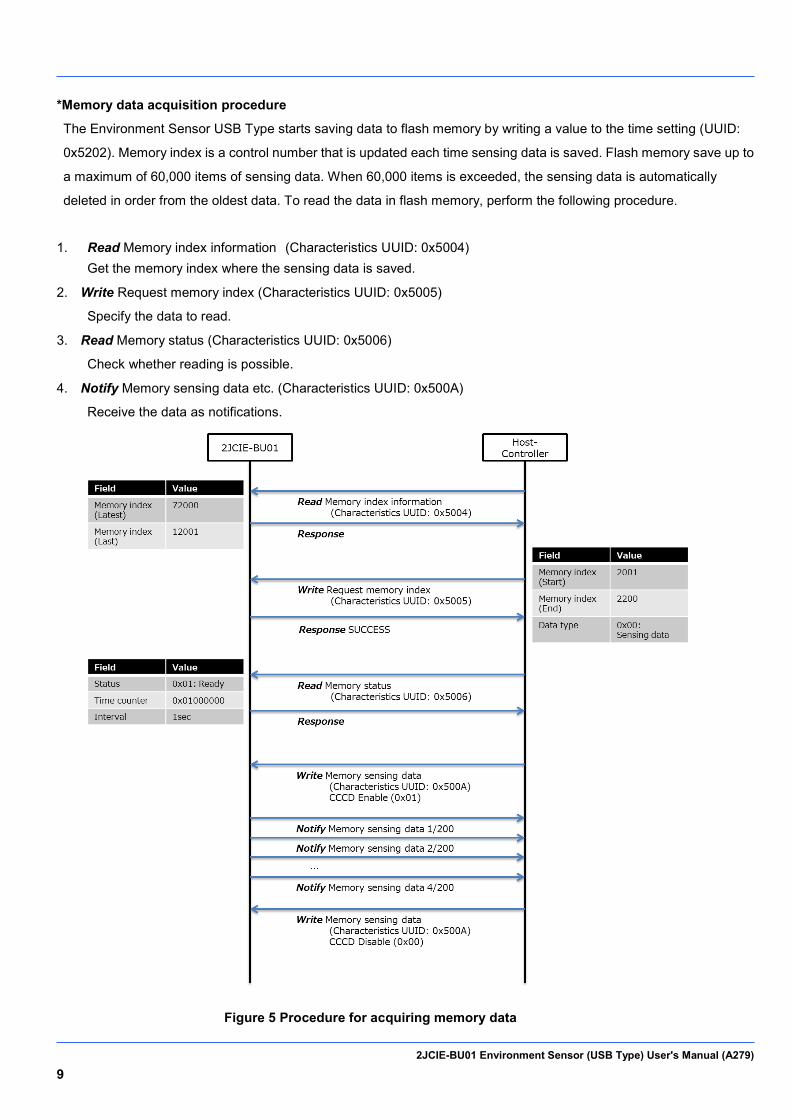
*Memory data acquisition procedure
The Environment Sensor USB Type starts saving data to flash memory by writing a value to the time setting (UUID:
0x5202). Memory index is a control number that is updated each time sensing data is saved. Flash memory save up to
a maximum of 60,000 items of sensing data. When 60,000 items is exceeded, the sensing data is automatically
deleted in order from the oldest data. To read the data in flash memory, perform the following procedure.
1. Read Memory index information (Characteristics UUID: 0x5004) Get the memory index where the sensing data is saved.
2. Write Request memory index (Characteristics UUID: 0x5005)
Specify the data to read.
3. Read Memory status (Characteristics UUID: 0x5006)
Check whether reading is possible.
4. Notify Memory sensing data etc. (Characteristics UUID: 0x500A)
Receive the data as notifications.
Figure 5 Procedure for acquiring memory data
2JCIE-BU01 Environment Sensor (USB Type) User's Manual (A279) 10
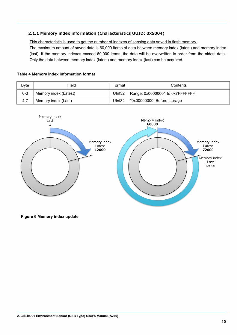
2.1.1 Memory index information (Characteristics UUID: 0x5004)
This characteristic is used to get the number of indexes of sensing data saved in flash memory. The maximum amount of saved data is 60,000 items of data between memory index (latest) and memory index (last). If the memory indexes exceed 60,000 items, the data will be overwritten in order from the oldest data. Only the data between memory index (latest) and memory index (last) can be acquired.
Table 4 Memory index information format
Byte Field Format Contents
0-3 Memory index (Latest) UInt32 Range: 0x00000001 to 0x7FFFFFFF
*0x00000000: Before storage 4-7 Memory index (Last) UInt32
Figure 6 Memory index update
2JCIE-BU01 Environment Sensor (USB Type) User's Manual (A279) 11
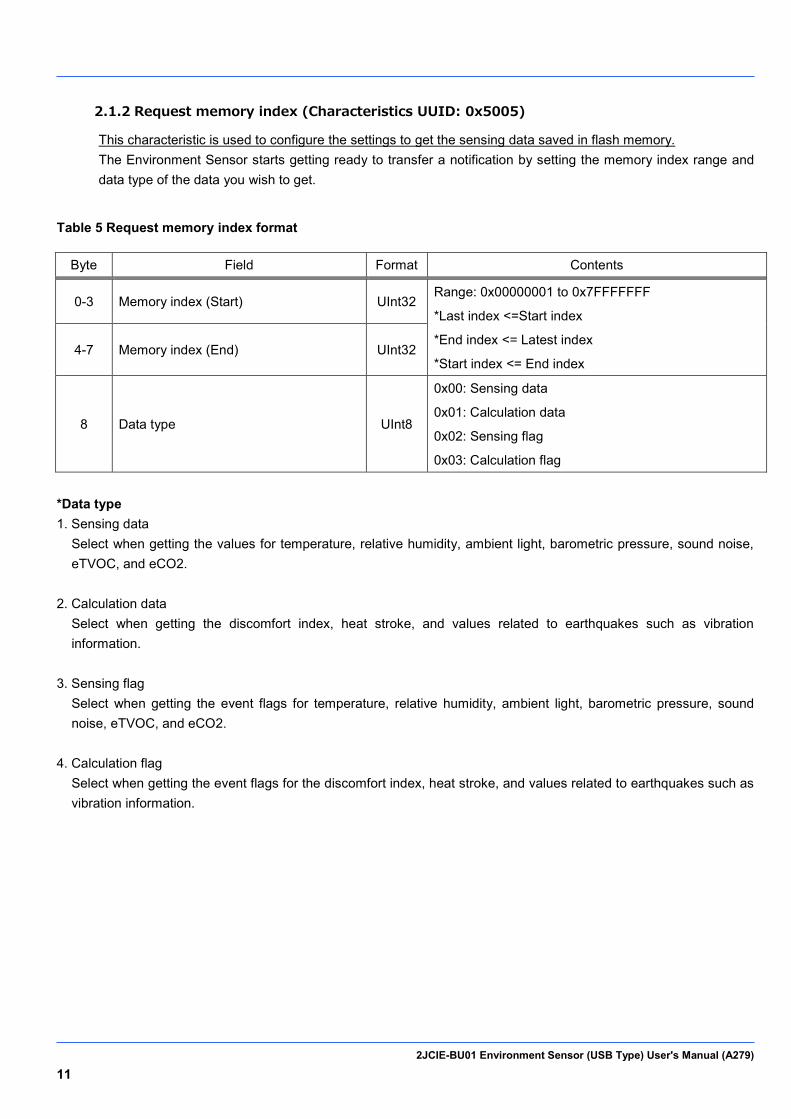
2.1.2 Request memory index (Characteristics UUID: 0x5005)
This characteristic is used to configure the settings to get the sensing data saved in flash memory. The Environment Sensor starts getting ready to transfer a notification by setting the memory index range and data type of the data you wish to get.
Table 5 Request memory index format
Byte Field Format Contents
0-3 Memory index (Start) UInt32 Range: 0x00000001 to 0x7FFFFFFF
*Last index <=Start index
*End index <= Latest index
*Start index <= End index 4-7 Memory index (End) UInt32
8 Data type UInt8
0x00: Sensing data
0x01: Calculation data
0x02: Sensing flag
0x03: Calculation flag
*Data type 1. Sensing data
Select when getting the values for temperature, relative humidity, ambient light, barometric pressure, sound noise, eTVOC, and eCO2.
2. Calculation data
Select when getting the discomfort index, heat stroke, and values related to earthquakes such as vibration information.
3. Sensing flag
Select when getting the event flags for temperature, relative humidity, ambient light, barometric pressure, sound noise, eTVOC, and eCO2.
4. Calculation flag
Select when getting the event flags for the discomfort index, heat stroke, and values related to earthquakes such as vibration information.

2JCIE-BU01 Environment Sensor (USB Type) User's Manual (A279) 12
2.1.3 Memory status (Characteristics UUID: 0x5006)
This characteristic is used to get the read status of the sensing data saved in flash memory. The data get request is issued with request memory index (UUID: 0x5005), and the data is ready to transfer if the status is ready to transfer (0x01). If there is a send preparation error, such as the specified range being incorrect, the status is Error (0x03).
Table 6 Memory status format
Byte Field Format Contents
0 Status UInt8
0x00: Waiting
0x01: Ready to transfer
0x02: Transferring
0x03: Error
1-8 Time counter UInt64 Range: 0x1 to 0xFFFFFFFFFFFFFFFF
9-10 Memory storage interval UInt16 Range: 0x0001 to 0x0E10 (1 to 3600sec)
Unit: 1sec
*Time counter Time counter of the specified memory index (Start) will be returned. The transfer packet of each item of data does not include time counter information, so time counter of the data that was received as notifications must be assigned by central device by utilizing these information (Time Counter and Memory storage interval). Example) Time counter = 0x00010000 Memory storage interval = 0x000A (10sec) Data 1: 0x00010000 (Time counter) Data 2: 0x0001000A (Time counter + Memory storage interval * 1) Data 3: 0x00010014 (Time counter + Memory storage interval * 2) Data 4: 0x0001001E (Time counter + Memory storage interval * 3) ... Data 20: 0x000100BE (Time counter + Memory storage interval * 19)
2JCIE-BU01 Environment Sensor (USB Type) User's Manual (A279) 13
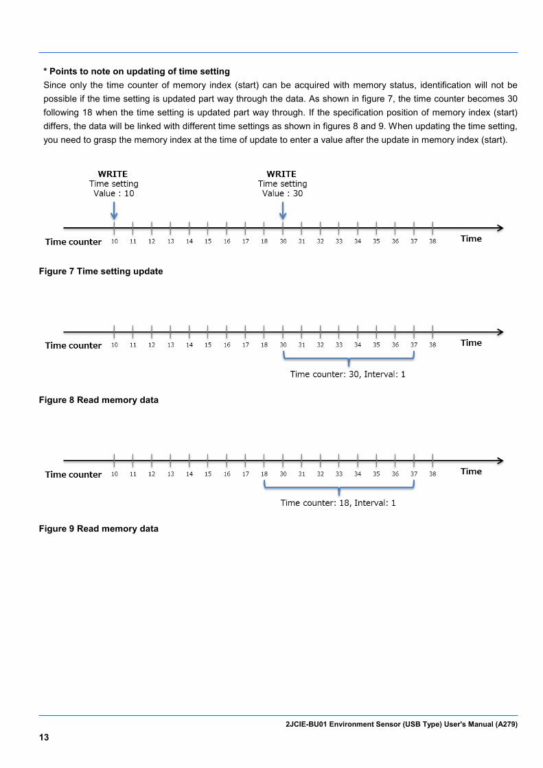
* Points to note on updating of time setting Since only the time counter of memory index (start) can be acquired with memory status, identification will not be possible if the time setting is updated part way through the data. As shown in figure 7, the time counter becomes 30 following 18 when the time setting is updated part way through. If the specification position of memory index (start) differs, the data will be linked with different time settings as shown in figures 8 and 9. When updating the time setting, you need to grasp the memory index at the time of update to enter a value after the update in memory index (start).
Figure 7 Time setting update
Figure 8 Read memory data
Figure 9 Read memory data

2JCIE-BU01 Environment Sensor (USB Type) User's Manual (A279) 14
2.1.4 Memory sensing data (Characteristics UUID: 0x500A)
This characteristic is used to get sensing data saved to flash memory as notifications. This is valid only when sensing data (0x00) is selected for the data type of request memory index. The transfer of data will begin as notifications when Client Characteristic Configuration Description (CCCD) is set to enable. If a reading failure occurred for the flash memory of the acquisition target, the most significant bit of the memory index is set to 1 and then the data is transferred.
Table 7 Memory sensing data format
Byte Field Format Contents
0-3 Memory index UInt32 Range: 0x00000001 to 0x7FFFFFFF
*If data error, MSB is 1
4-5 Temperature SInt16
Reference: 5.1. Output range
6-7 Relative humidity SInt16
8-9 Ambient light SInt16
10-13 Barometric pressure SInt32
14-15 Sound noise SInt16
16-17 eTVOC SInt16
18-19 eCO2 SInt16
2.1.5 Memory calculation data (Characteristics UUID: 0x500B)
This characteristic is used to get calculation data saved to flash memory as notifications. This is valid only when calculation data (0x01) is selected for the data type of request memory index. The transfer of data will begin as notifications when Client Characteristic Configuration Description (CCCD) is set to enable. If a reading failure occurred for the flash memory of the acquisition target, the most significant bit of the memory index is set to 1 and then the data is transferred.
Table 8 Memory calculation data format
Byte Field Format Contents
0-3 Memory index UInt32 Range: 0x00000001 to 0x7FFFFFFF
*If data error, MSB is 1
4-5 Discomfort index SInt16
Reference: 5.1. Output range
6-7 Heat stroke SInt16
8 Vibration information UInt8
9-10 SI value UInt16
11-12 PGA UInt16
13-14 Seismic intensity UInt16

2JCIE-BU01 Environment Sensor (USB Type) User's Manual (A279) 15
2.1.6 Memory sensing flag (Characteristics UUID: 0x500C)
This characteristic is used to get sensing flags saved to flash memory as notifications. This is valid only when sensing flag (0x02) is selected for the data type of request memory index. The transfer of data will begin as notifications when Client Characteristic Configuration Description (CCCD) is set to enable. If a reading failure occurred for the flash memory of the acquisition target, the most significant bit of the memory index is set to 1 and then the data is transferred.
Table 9 Memory sensing flag format
Byte Field Format Contents
0-3 Memory index UInt32 Range: 0x00000001 to 0x7FFFFFFF
*If data error, MSB is 1
4-5 Temperature flag UInt16
Reference: 5.3. Event flag
6-7 Relative humidity flag UInt16
8-9 Ambient light flag UInt16
10-11 Barometric pressure flag UInt16
12-13 Sound noise flag UInt16
14-15 eTVOC flag UInt16
16-17 eCO2 flag UInt16
2.1.7 Memory calculation flag (Characteristics UUID: 0x500D)
This characteristic is used to get calculation flags saved to flash memory as notifications. This is valid only when calculation flag (0x03) is selected for the data type of request memory index. The transfer of data will begin as notifications when Client Characteristic Configuration Description (CCCD) is set to enable. If a reading failure occurred for the flash memory of the acquisition target, the most significant bit of the memory index is set to 1 and then the data is transferred.
Table 10 Memory calculation flag format
Byte Field Format Contents
0-3 Memory index UInt32 Range: 0x00000001 to 0x7FFFFFFF
*If data error, MSB is 1
4-5 Discomfort index flag UInt16
Reference: 5.3. Event flag
6-7 Heat stroke flag UInt16
8 SI value flag UInt8
9 PGA flag UInt8
10 Seismic intensity flag UInt8
2JCIE-BU01 Environment Sensor (USB Type) User's Manual (A279) 16
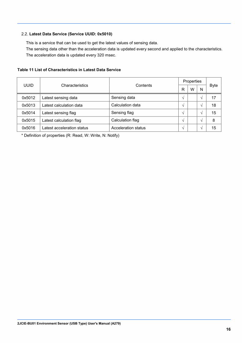
Latest Data Service (Service UUID: 0x5010) 2.2.
This is a service that can be used to get the latest values of sensing data. The sensing data other than the acceleration data is updated every second and applied to the characteristics. The acceleration data is updated every 320 msec.
Table 11 List of Characteristics in Latest Data Service
UUID Characteristics Contents Properties
Byte R W N
0x5012 Latest sensing data Sensing data √ √ 17
0x5013 Latest calculation data Calculation data √ √ 18
0x5014 Latest sensing flag Sensing flag √ √ 15
0x5015 Latest calculation flag Calculation flag √ √ 8
0x5016 Latest acceleration status Acceleration status √ √ 15
* Definition of properties (R: Read, W: Write, N: Notify)
2JCIE-BU01 Environment Sensor (USB Type) User's Manual (A279) 17
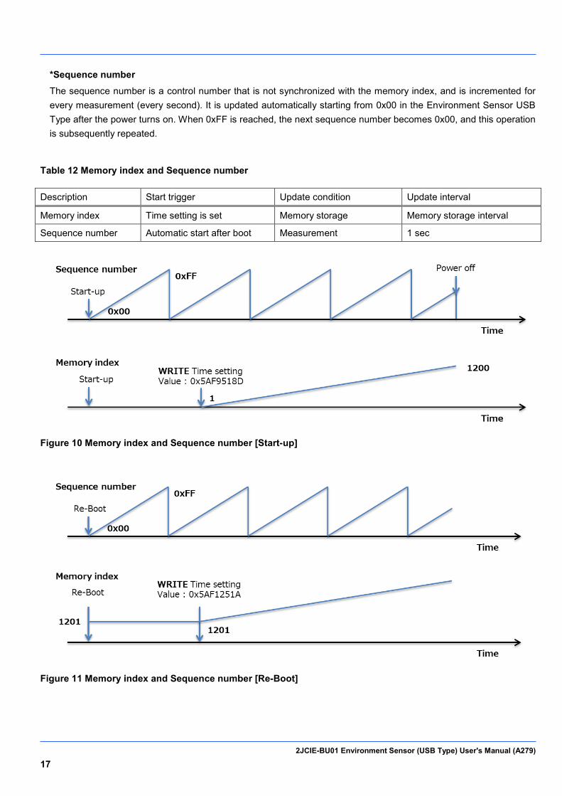
*Sequence number
The sequence number is a control number that is not synchronized with the memory index, and is incremented for every measurement (every second). It is updated automatically starting from 0x00 in the Environment Sensor USB Type after the power turns on. When 0xFF is reached, the next sequence number becomes 0x00, and this operation is subsequently repeated.
Table 12 Memory index and Sequence number
Description Start trigger Update condition Update interval
Memory index Time setting is set Memory storage Memory storage interval
Sequence number Automatic start after boot Measurement 1 sec
Figure 10 Memory index and Sequence number [Start-up]
Figure 11 Memory index and Sequence number [Re-Boot]
2JCIE-BU01 Environment Sensor (USB Type) User's Manual (A279) 18
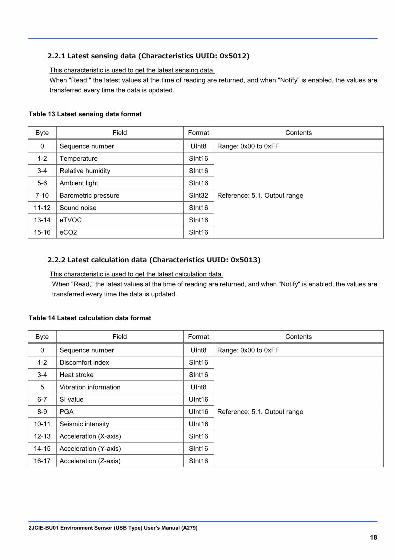
2.2.1 Latest sensing data (Characteristics UUID: 0x5012)
This characteristic is used to get the latest sensing data. When "Read," the latest values at the time of reading are returned, and when "Notify" is enabled, the values are transferred every time the data is updated.
Table 13 Latest sensing data format
Byte Field Format Contents
0 Sequence number UInt8 Range: 0x00 to 0xFF
1-2 Temperature SInt16
Reference: 5.1. Output range
3-4 Relative humidity SInt16
5-6 Ambient light SInt16
7-10 Barometric pressure SInt32
11-12 Sound noise SInt16
13-14 eTVOC SInt16
15-16 eCO2 SInt16
2.2.2 Latest calculation data (Characteristics UUID: 0x5013)
This characteristic is used to get the latest calculation data. When "Read," the latest values at the time of reading are returned, and when "Notify" is enabled, the values are transferred every time the data is updated.
Table 14 Latest calculation data format
Byte Field Format Contents
0 Sequence number UInt8 Range: 0x00 to 0xFF
1-2 Discomfort index SInt16
Reference: 5.1. Output range
3-4 Heat stroke SInt16
5 Vibration information UInt8
6-7 SI value UInt16
8-9 PGA UInt16
10-11 Seismic intensity UInt16
12-13 Acceleration (X-axis) SInt16
14-15 Acceleration (Y-axis) SInt16
16-17 Acceleration (Z-axis) SInt16

2JCIE-BU01 Environment Sensor (USB Type) User's Manual (A279) 19
2.2.3 Latest sensing flag (Characteristics UUID: 0x5014)
This characteristic is used to get the latest sensing flags. When "Read," the latest values at the time of reading are returned, and when "Notify" is enabled, the values are transferred every time the data is updated.
Table 15 Latest sensing flag format
Byte Field Format Contents
0 Sequence number UInt8 Range: 0x00 to 0xFF
1-2 Temperature flag UInt16
Reference: 5.3. Event flag
3-4 Relative humidity flag UInt16
5-6 Ambient light flag UInt16
7-8 Barometric pressure flag UInt16
9-10 Sound noise flag UInt16
11-12 eTVOC flag UInt16
13-14 eCO2 flag UInt16
2.2.4 Latest calculation flag (Characteristics UUID: 0x5015)
This characteristic is used to get the latest calculation flag. When "Read," the latest values at the time of reading are returned, and when "Notify" is enabled, the values are transferred every time the data is updated.
Table 16 Latest calculation flag format
Byte Field Format Contents
0 Sequence number UInt8 Range: 0x00 to 0xFF
1-2 Discomfort index flag UInt16
Reference: 5.3. Event flag
3-4 Heat stroke flag UInt16
5 SI value flag UInt8
6 PGA flag UInt8
7 Seismic intensity flag UInt8
2JCIE-BU01 Environment Sensor (USB Type) User's Manual (A279) 20
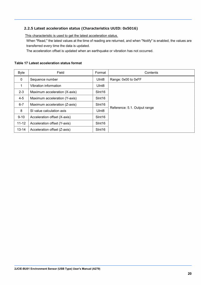
2.2.5 Latest acceleration status (Characteristics UUID: 0x5016)
This characteristic is used to get the latest acceleration status. When "Read," the latest values at the time of reading are returned, and when "Notify" is enabled, the values are transferred every time the data is updated. The acceleration offset is updated when an earthquake or vibration has not occurred.
Table 17 Latest acceleration status format
Byte Field Format Contents
0 Sequence number UInt8 Range: 0x00 to 0xFF
1 Vibration information UInt8
Reference: 5.1. Output range
2-3 Maximum acceleration (X-axis) SInt16
4-5 Maximum acceleration (Y-axis) SInt16
6-7 Maximum acceleration (Z-axis) SInt16
8 SI value calculation axis UInt8
9-10 Acceleration offset (X-axis) SInt16
11-12 Acceleration offset (Y-axis) SInt16
13-14 Acceleration offset (Z-axis) SInt16

2JCIE-BU01 Environment Sensor (USB Type) User's Manual (A279) 21
Acceleration Service (Service UUID: 0x5030) 2.3.
This is a service that can be used to get acceleration data saved in flash memory.
Table 18 List of Characteristics in Acceleration Service
UUID Characteristics Contents Properties
Byte R W N
0x5031 Vibration count Accumulated earthquake/vibration
count √
8
0x5032 Request acceleration memory index Specify acceleration memory index
√
6
0x5033 Acceleration memory status Read status of acceleration memory √
3
0x5034 Acceleration memory data Read acceleration data
√ 20
* Definition of properties (R: Read, W: Write, N: Notify)

2JCIE-BU01 Environment Sensor (USB Type) User's Manual (A279) 22
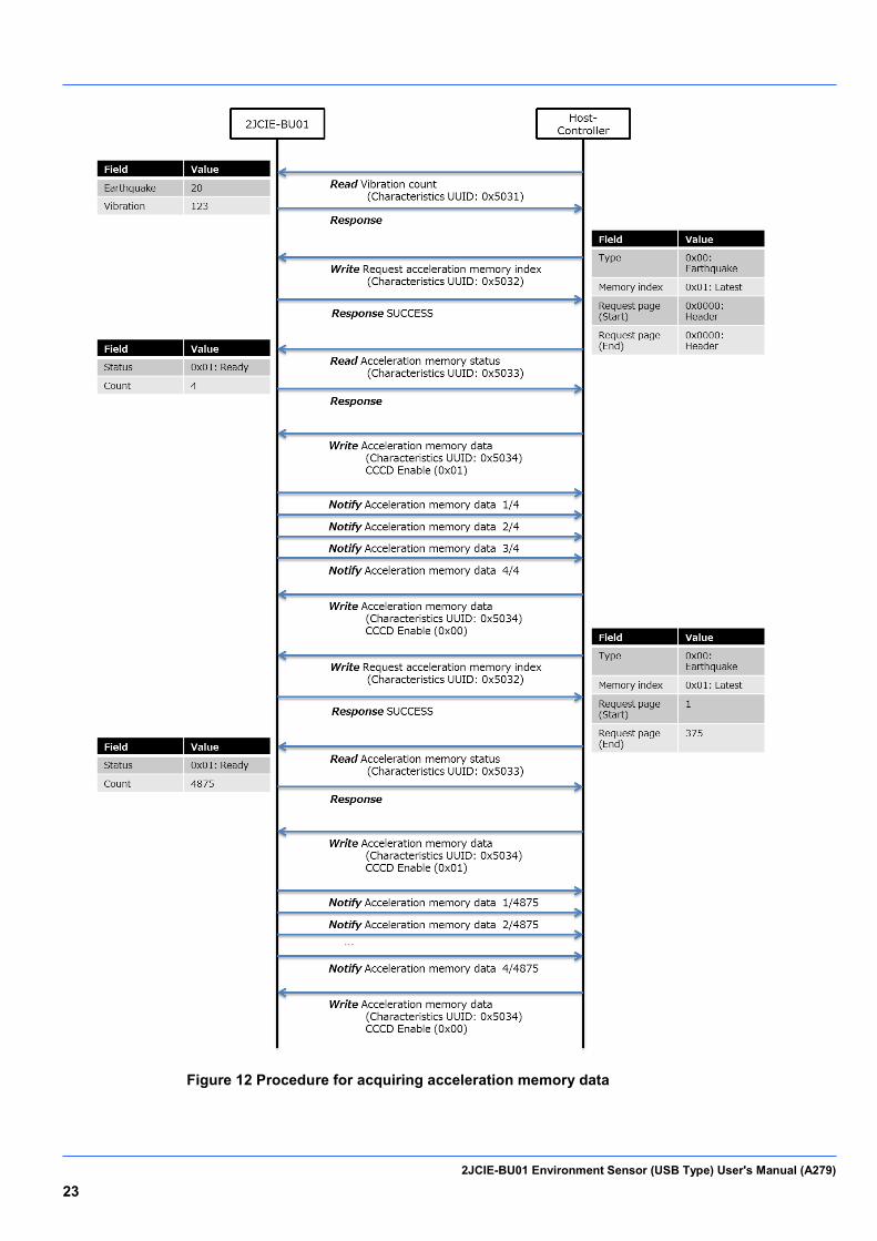
*Acceleration memory data acquisition procedure [Normal mode]
Data saving starts for an earthquake/vibration if vibration is detected even before a value is written to the time setting
(UUID: 0x5202). There is a time counter for the acquisition data format, but it becomes 0 when the time setting is not
written. To read the data in flash memory, perform the following procedure. The amount of earthquake data is fixed to
375 pages, but since the vibration data varies depending on the vibration time, the total number of pages can be
checked by reading the header page.
1. Read Vibration count (Characteristics UUID: 0x5031)
Get the count value for saved earthquake/vibration data.
2. Write Request acceleration memory index (Characteristics UUID: 0x5032) Specify the header page.
3. Read Acceleration memory status (Characteristics UUID: 0x5033) Check whether reading is possible.
4. Notify Memory sensing data etc. (Characteristics UUID: 0x500A)
Receive the data as notifications.
5. Write Request acceleration memory index (Characteristics UUID: 0x5032) Specify the pages to get.
6. Read Acceleration memory status (Characteristics UUID: 0x5033) Check whether reading is possible.
7. Notify Memory sensing data etc. (Characteristics UUID: 0x500A)
Receive the data as notifications.
2JCIE-BU01 Environment Sensor (USB Type) User's Manual (A279) 23
Figure 12 Procedure for acquiring acceleration memory data
2JCIE-BU01 Environment Sensor (USB Type) User's Manual (A279) 24
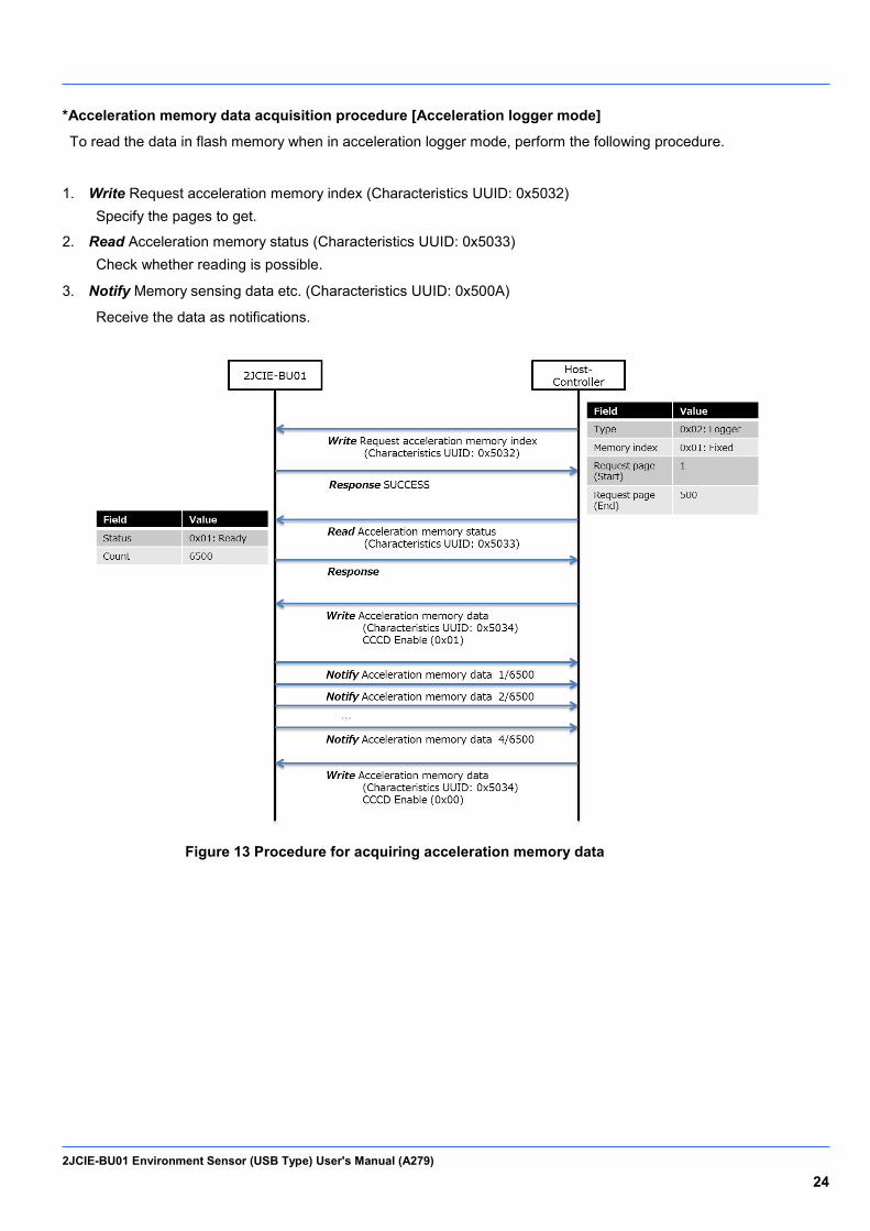
*Acceleration memory data acquisition procedure [Acceleration logger mode]
To read the data in flash memory when in acceleration logger mode, perform the following procedure.
1. Write Request acceleration memory index (Characteristics UUID: 0x5032) Specify the pages to get.
2. Read Acceleration memory status (Characteristics UUID: 0x5033) Check whether reading is possible.
3. Notify Memory sensing data etc. (Characteristics UUID: 0x500A)
Receive the data as notifications.
Figure 13 Procedure for acquiring acceleration memory data
2JCIE-BU01 Environment Sensor (USB Type) User's Manual (A279) 25
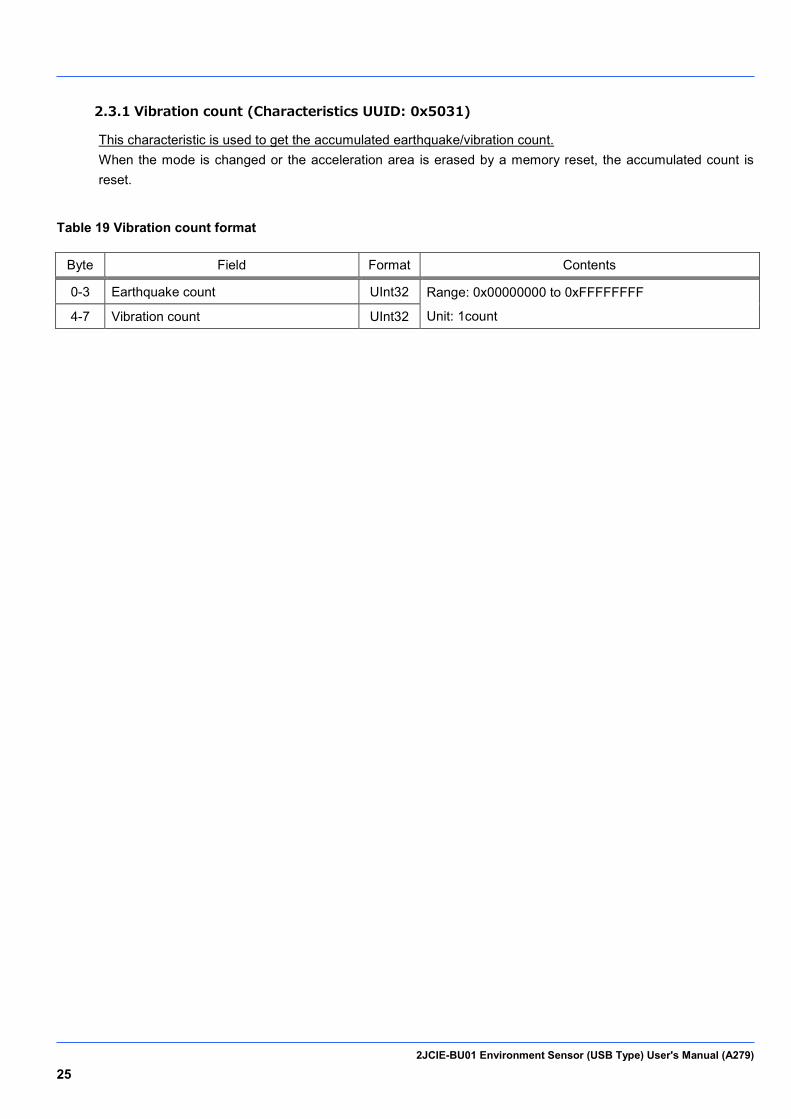
2.3.1 Vibration count (Characteristics UUID: 0x5031)
This characteristic is used to get the accumulated earthquake/vibration count. When the mode is changed or the acceleration area is erased by a memory reset, the accumulated count is reset.
Table 19 Vibration count format
Byte Field Format Contents
0-3 Earthquake count UInt32 Range: 0x00000000 to 0xFFFFFFFF
Unit: 1count 4-7 Vibration count UInt32
2JCIE-BU01 Environment Sensor (USB Type) User's Manual (A279) 26
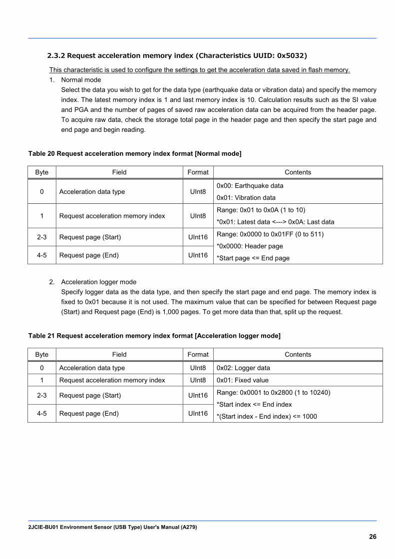
2.3.2 Request acceleration memory index (Characteristics UUID: 0x5032)
This characteristic is used to configure the settings to get the acceleration data saved in flash memory. 1. Normal mode
Select the data you wish to get for the data type (earthquake data or vibration data) and specify the memory index. The latest memory index is 1 and last memory index is 10. Calculation results such as the SI value and PGA and the number of pages of saved raw acceleration data can be acquired from the header page. To acquire raw data, check the storage total page in the header page and then specify the start page and end page and begin reading.
Table 20 Request acceleration memory index format [Normal mode]
Byte Field Format Contents
0 Acceleration data type UInt8 0x00: Earthquake data
0x01: Vibration data
1 Request acceleration memory index UInt8 Range: 0x01 to 0x0A (1 to 10)
*0x01: Latest data <---> 0x0A: Last data
2-3 Request page (Start) UInt16 Range: 0x0000 to 0x01FF (0 to 511)
*0x0000: Header page
*Start page <= End page 4-5 Request page (End) UInt16
2. Acceleration logger mode Specify logger data as the data type, and then specify the start page and end page. The memory index is fixed to 0x01 because it is not used. The maximum value that can be specified for between Request page (Start) and Request page (End) is 1,000 pages. To get more data than that, split up the request.
Table 21 Request acceleration memory index format [Acceleration logger mode]
Byte Field Format Contents
0 Acceleration data type UInt8 0x02: Logger data
1 Request acceleration memory index UInt8 0x01: Fixed value
2-3 Request page (Start) UInt16 Range: 0x0001 to 0x2800 (1 to 10240)
*Start index <= End index
*(Start index - End index) <= 1000 4-5 Request page (End) UInt16

2JCIE-BU01 Environment Sensor (USB Type) User's Manual (A279) 27
2.3.3 Acceleration memory status (Characteristics UUID: 0x5033)
This characteristic is used to get the read status of the acceleration data saved in flash memory. After the data in the request acceleration memory index is specified, the data is ready to transfer if the status is ready to transfer (0x01), and the total number of notifications to be transferred (total transfer count) from then can be checked.
Table 22 Acceleration memory status format
Byte Field Format Contents
0 Status UInt8
0x00: Waiting
0x01: Ready to transfer
0x02: Transferring
0x03: Error
1-2 Total transfer count UInt16 Range: 0x0001 to 0x7FFF
2JCIE-BU01 Environment Sensor (USB Type) User's Manual (A279) 28
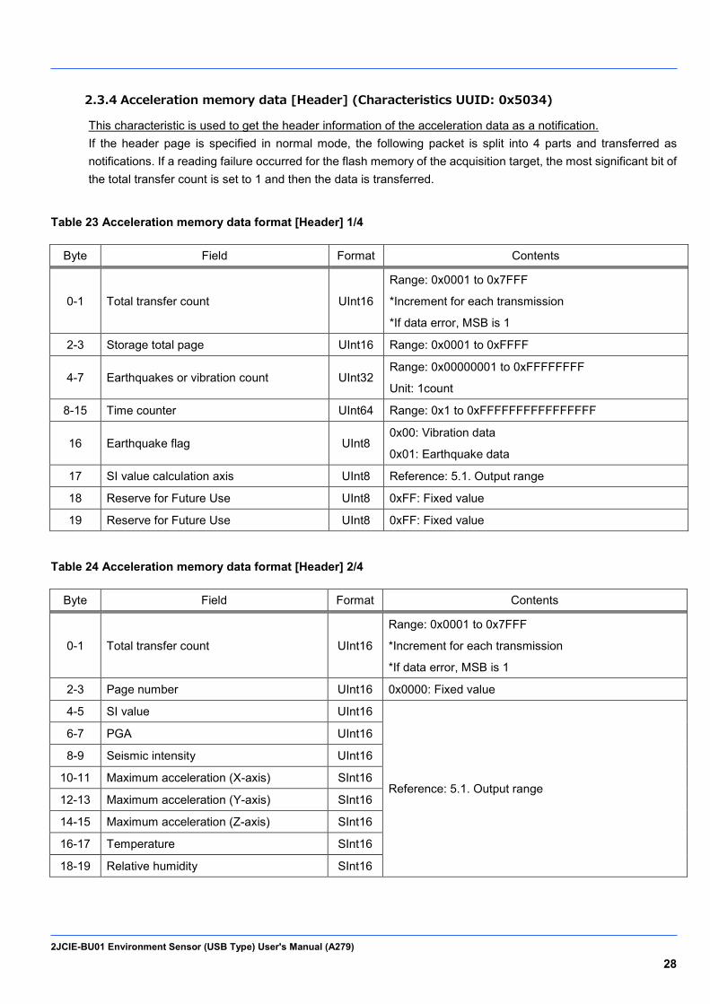
2.3.4 Acceleration memory data [Header] (Characteristics UUID: 0x5034)
This characteristic is used to get the header information of the acceleration data as a notification. If the header page is specified in normal mode, the following packet is split into 4 parts and transferred as notifications. If a reading failure occurred for the flash memory of the acquisition target, the most significant bit of the total transfer count is set to 1 and then the data is transferred.
Table 23 Acceleration memory data format [Header] 1/4
Byte Field Format Contents
0-1 Total transfer count UInt16
Range: 0x0001 to 0x7FFF
*Increment for each transmission
*If data error, MSB is 1
2-3 Storage total page UInt16 Range: 0x0001 to 0xFFFF
4-7 Earthquakes or vibration count UInt32 Range: 0x00000001 to 0xFFFFFFFF
Unit: 1count
8-15 Time counter UInt64 Range: 0x1 to 0xFFFFFFFFFFFFFFFF
16 Earthquake flag UInt8 0x00: Vibration data
0x01: Earthquake data
17 SI value calculation axis UInt8 Reference: 5.1. Output range
18 Reserve for Future Use UInt8 0xFF: Fixed value
19 Reserve for Future Use UInt8 0xFF: Fixed value
Table 24 Acceleration memory data format [Header] 2/4
Byte Field Format Contents
0-1 Total transfer count UInt16
Range: 0x0001 to 0x7FFF
*Increment for each transmission
*If data error, MSB is 1
2-3 Page number UInt16 0x0000: Fixed value
4-5 SI value UInt16
Reference: 5.1. Output range
6-7 PGA UInt16
8-9 Seismic intensity UInt16
10-11 Maximum acceleration (X-axis) SInt16
12-13 Maximum acceleration (Y-axis) SInt16
14-15 Maximum acceleration (Z-axis) SInt16
16-17 Temperature SInt16
18-19 Relative humidity SInt16
2JCIE-BU01 Environment Sensor (USB Type) User's Manual (A279) 29
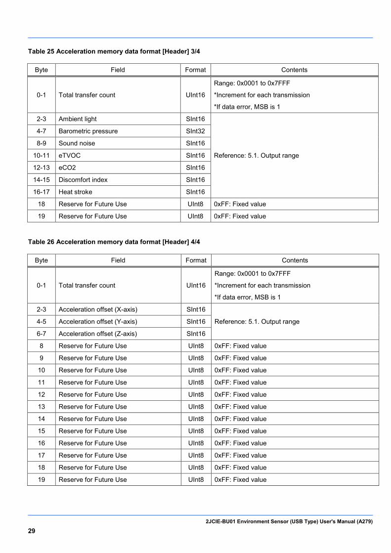
Table 25 Acceleration memory data format [Header] 3/4
Byte Field Format Contents
0-1 Total transfer count UInt16
Range: 0x0001 to 0x7FFF
*Increment for each transmission
*If data error, MSB is 1
2-3 Ambient light SInt16
Reference: 5.1. Output range
4-7 Barometric pressure SInt32
8-9 Sound noise SInt16
10-11 eTVOC SInt16
12-13 eCO2 SInt16
14-15 Discomfort index SInt16
16-17 Heat stroke SInt16
18 Reserve for Future Use UInt8 0xFF: Fixed value
19 Reserve for Future Use UInt8 0xFF: Fixed value
Table 26 Acceleration memory data format [Header] 4/4
Byte Field Format Contents
0-1 Total transfer count UInt16
Range: 0x0001 to 0x7FFF
*Increment for each transmission
*If data error, MSB is 1
2-3 Acceleration offset (X-axis) SInt16
Reference: 5.1. Output range 4-5 Acceleration offset (Y-axis) SInt16
6-7 Acceleration offset (Z-axis) SInt16
8 Reserve for Future Use UInt8 0xFF: Fixed value
9 Reserve for Future Use UInt8 0xFF: Fixed value
10 Reserve for Future Use UInt8 0xFF: Fixed value
11 Reserve for Future Use UInt8 0xFF: Fixed value
12 Reserve for Future Use UInt8 0xFF: Fixed value
13 Reserve for Future Use UInt8 0xFF: Fixed value
14 Reserve for Future Use UInt8 0xFF: Fixed value
15 Reserve for Future Use UInt8 0xFF: Fixed value
16 Reserve for Future Use UInt8 0xFF: Fixed value
17 Reserve for Future Use UInt8 0xFF: Fixed value
18 Reserve for Future Use UInt8 0xFF: Fixed value
19 Reserve for Future Use UInt8 0xFF: Fixed value
2JCIE-BU01 Environment Sensor (USB Type) User's Manual (A279) 30
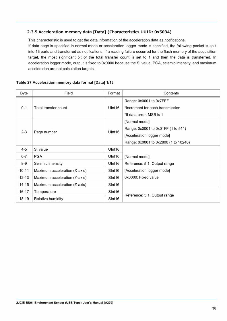
2.3.5 Acceleration memory data [Data] (Characteristics UUID: 0x5034)
This characteristic is used to get the data information of the acceleration data as notifications. If data page is specified in normal mode or acceleration logger mode is specified, the following packet is split into 13 parts and transferred as notifications. If a reading failure occurred for the flash memory of the acquisition target, the most significant bit of the total transfer count is set to 1 and then the data is transferred. In acceleration logger mode, output is fixed to 0x0000 because the SI value, PGA, seismic intensity, and maximum acceleration are not calculation targets.
Table 27 Acceleration memory data format [Data] 1/13
Byte Field Format Contents
0-1 Total transfer count UInt16
Range: 0x0001 to 0x7FFF
*Increment for each transmission
*If data error, MSB is 1
2-3 Page number UInt16
[Normal mode]
Range: 0x0001 to 0x01FF (1 to 511)
[Acceleration logger mode]
Range: 0x0001 to 0x2800 (1 to 10240)
4-5 SI value UInt16
[Normal mode]
Reference: 5.1. Output range
[Acceleration logger mode]
0x0000: Fixed value
6-7 PGA UInt16
8-9 Seismic intensity UInt16
10-11 Maximum acceleration (X-axis) SInt16
12-13 Maximum acceleration (Y-axis) SInt16
14-15 Maximum acceleration (Z-axis) SInt16
16-17 Temperature SInt16 Reference: 5.1. Output range
18-19 Relative humidity SInt16
2JCIE-BU01 Environment Sensor (USB Type) User's Manual (A279) 31
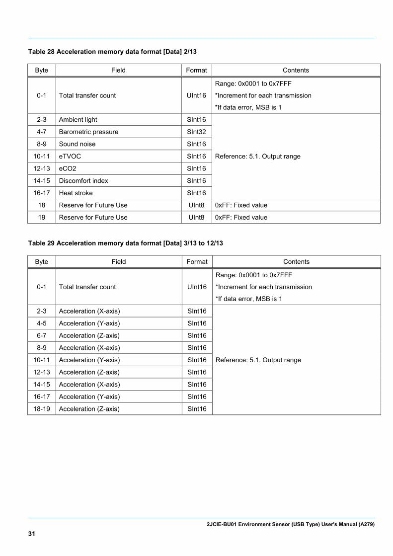
Table 28 Acceleration memory data format [Data] 2/13
Byte Field Format Contents
0-1 Total transfer count UInt16
Range: 0x0001 to 0x7FFF
*Increment for each transmission
*If data error, MSB is 1
2-3 Ambient light SInt16
Reference: 5.1. Output range
4-7 Barometric pressure SInt32
8-9 Sound noise SInt16
10-11 eTVOC SInt16
12-13 eCO2 SInt16
14-15 Discomfort index SInt16
16-17 Heat stroke SInt16
18 Reserve for Future Use UInt8 0xFF: Fixed value
19 Reserve for Future Use UInt8 0xFF: Fixed value
Table 29 Acceleration memory data format [Data] 3/13 to 12/13
Byte Field Format Contents
0-1 Total transfer count UInt16
Range: 0x0001 to 0x7FFF
*Increment for each transmission
*If data error, MSB is 1
2-3 Acceleration (X-axis) SInt16
Reference: 5.1. Output range
4-5 Acceleration (Y-axis) SInt16
6-7 Acceleration (Z-axis) SInt16
8-9 Acceleration (X-axis) SInt16
10-11 Acceleration (Y-axis) SInt16
12-13 Acceleration (Z-axis) SInt16
14-15 Acceleration (X-axis) SInt16
16-17 Acceleration (Y-axis) SInt16
18-19 Acceleration (Z-axis) SInt16
2JCIE-BU01 Environment Sensor (USB Type) User's Manual (A279) 32
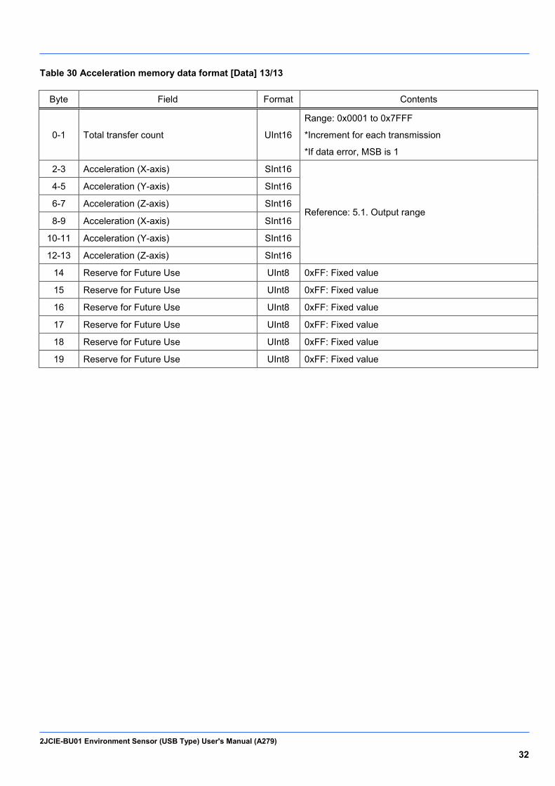
Table 30 Acceleration memory data format [Data] 13/13
Byte Field Format Contents
0-1 Total transfer count UInt16
Range: 0x0001 to 0x7FFF
*Increment for each transmission
*If data error, MSB is 1
2-3 Acceleration (X-axis) SInt16
Reference: 5.1. Output range
4-5 Acceleration (Y-axis) SInt16
6-7 Acceleration (Z-axis) SInt16
8-9 Acceleration (X-axis) SInt16
10-11 Acceleration (Y-axis) SInt16
12-13 Acceleration (Z-axis) SInt16
14 Reserve for Future Use UInt8 0xFF: Fixed value
15 Reserve for Future Use UInt8 0xFF: Fixed value
16 Reserve for Future Use UInt8 0xFF: Fixed value
17 Reserve for Future Use UInt8 0xFF: Fixed value
18 Reserve for Future Use UInt8 0xFF: Fixed value
19 Reserve for Future Use UInt8 0xFF: Fixed value
2JCIE-BU01 Environment Sensor (USB Type) User's Manual (A279) 33
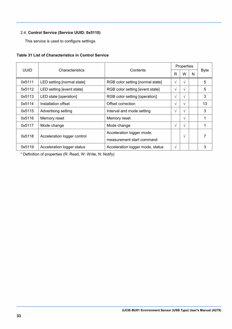
Control Service (Service UUID: 0x5110) 2.4.
This service is used to configure settings.
Table 31 List of Characteristics in Control Service
UUID Characteristics Contents Properties
Byte R W N
0x5111 LED setting [normal state] RGB color setting [normal state] √ √
5
0x5112 LED setting [event state] RGB color setting [event state] √ √
5
0x5113 LED state [operation] RGB color setting [operation] √ √
3
0x5114 Installation offset Offset correction √ √ 13
0x5115 Advertising setting Interval and mode setting √ √ 3
0x5116 Memory reset Memory reset √ 1
0x5117 Mode change Mode change √ √ 1
0x5118 Acceleration logger control Acceleration logger mode,
measurement start command √ 7
0x5119 Acceleration logger status Acceleration logger mode, status √
3
* Definition of properties (R: Read, W: Write, N: Notify)
2JCIE-BU01 Environment Sensor (USB Type) User's Manual (A279) 34
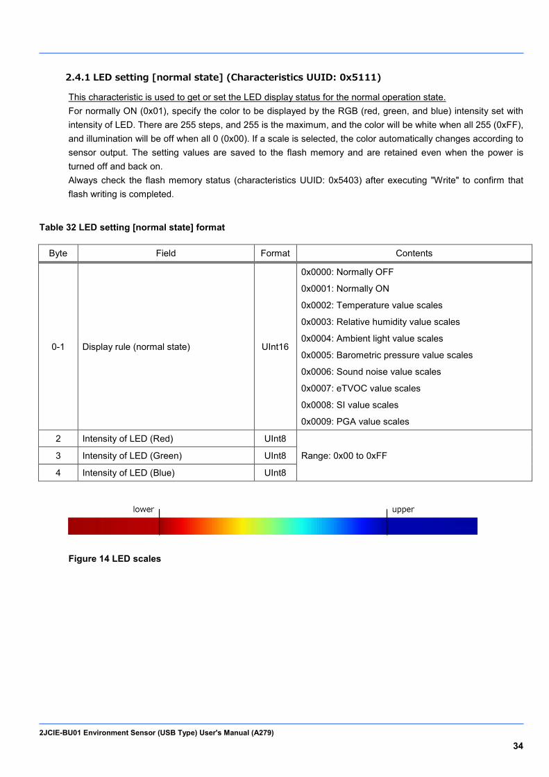
2.4.1 LED setting [normal state] (Characteristics UUID: 0x5111)
This characteristic is used to get or set the LED display status for the normal operation state. For normally ON (0x01), specify the color to be displayed by the RGB (red, green, and blue) intensity set with intensity of LED. There are 255 steps, and 255 is the maximum, and the color will be white when all 255 (0xFF), and illumination will be off when all 0 (0x00). If a scale is selected, the color automatically changes according to sensor output. The setting values are saved to the flash memory and are retained even when the power is turned off and back on. Always check the flash memory status (characteristics UUID: 0x5403) after executing "Write" to confirm that flash writing is completed.
Table 32 LED setting [normal state] format
Byte Field Format Contents
0-1 Display rule (normal state) UInt16
0x0000: Normally OFF
0x0001: Normally ON
0x0002: Temperature value scales
0x0003: Relative humidity value scales
0x0004: Ambient light value scales
0x0005: Barometric pressure value scales
0x0006: Sound noise value scales
0x0007: eTVOC value scales
0x0008: SI value scales
0x0009: PGA value scales
2 Intensity of LED (Red) UInt8
Range: 0x00 to 0xFF 3 Intensity of LED (Green) UInt8
4 Intensity of LED (Blue) UInt8
Figure 14 LED scales
2JCIE-BU01 Environment Sensor (USB Type) User's Manual (A279) 35
Table 33 Upper and lower limits of LED scales
Display rule Sensor type Lower value Upper value Unit
0x0002 Temperature 10.00 35.00 degC
0x0003 Relative humidity 20.00 80.00 %RH
0x0004 Ambient light 0 10000 Lx
0x0005 Barometric pressure 950.000 1050.000 hPa
0x0006 Sound noise 35.00 80.00 dB
0x0007 eTVOC 0 1000 ppb
0x0008 SI value 0 60.0 kine
0x0009 PGA 0 300.0 gal
2.4.2 LED setting [event state] (Characteristics UUID: 0x5112)
This characteristic is used to get or set the LED display status when an event occurs. For when an event occurs, specify the color to flash by the RGB (red, green, blue) intensity set with intensity of LED. There are 255 steps, and 255 is the maximum, and the color will be white when all 255 (0xFF), and illumination will be off when all 0 (0x00). Events are bit field settings so multiple events can be set at the same time. The setting values are saved to the flash memory and are retained even when the power is turned off and back on. Always check the flash memory status (characteristics UUID: 0x5403) after executing "Write" to confirm that flash writing is completed.
Table 34 LED setting [event state] format
Byte Field Format Contents
0-1 Display rule (event state) UInt16
Bit7: PGA event
Bit6: SI value event
Bit5: eTVOC event
Bit4: Sound noise event
Bit3: Barometric pressure event
Bit2: Ambient light event
Bit1: Relative humidity event
Bit0: Temperature event
2 Intensity of LED (Red) UInt8
Range : 0x00 to 0xFF 3 Intensity of LED (Green) UInt8
4 Intensity of LED (Blue) UInt8
2JCIE-BU01 Environment Sensor (USB Type) User's Manual (A279) 36
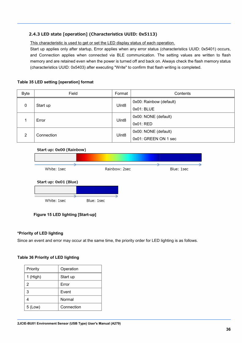
2.4.3 LED state [operation] (Characteristics UUID: 0x5113)
This characteristic is used to get or set the LED display status of each operation. Start up applies only after startup, Error applies when any error status (characteristics UUID: 0x5401) occurs, and Connection applies when connected via BLE communication. The setting values are written to flash memory and are retained even when the power is turned off and back on. Always check the flash memory status (characteristics UUID: 0x5403) after executing "Write" to confirm that flash writing is completed.
Table 35 LED setting [operation] format
Byte Field Format Contents
0 Start up UInt8 0x00: Rainbow (default)
0x01: BLUE
1 Error UInt8 0x00: NONE (default)
0x01: RED
2 Connection UInt8 0x00: NONE (default)
0x01: GREEN ON 1 sec
Figure 15 LED lighting [Start-up]
*Priority of LED lighting
Since an event and error may occur at the same time, the priority order for LED lighting is as follows.
Table 36 Priority of LED lighting
Priority Operation
1 (High) Start up
2 Error
3 Event
4 Normal
5 (Low) Connection
2JCIE-BU01 Environment Sensor (USB Type) User's Manual (A279) 37
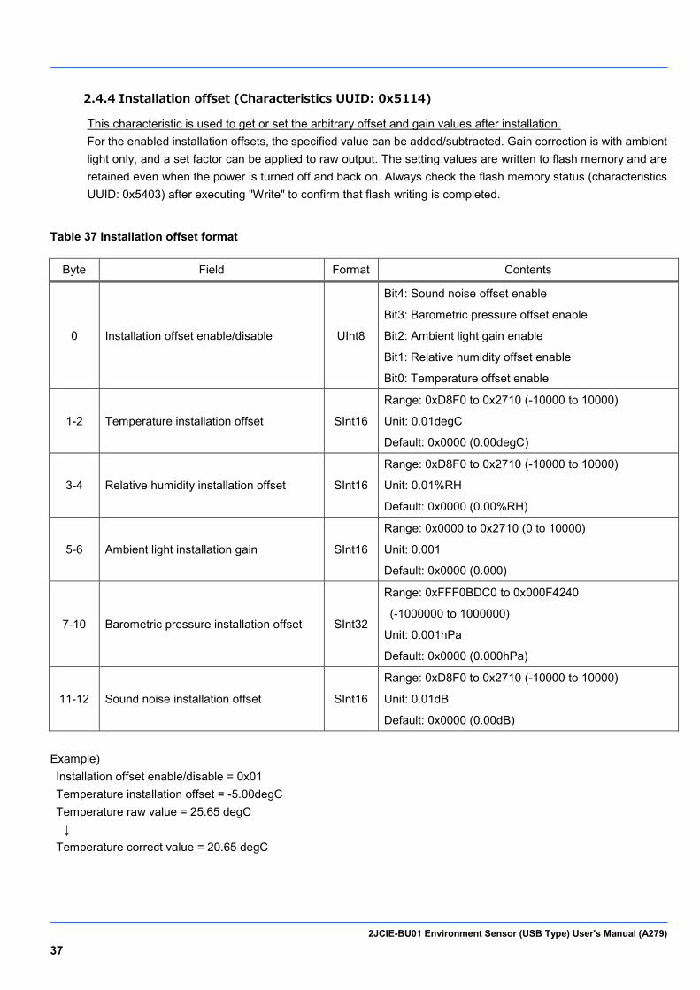
2.4.4 Installation offset (Characteristics UUID: 0x5114)
This characteristic is used to get or set the arbitrary offset and gain values after installation. For the enabled installation offsets, the specified value can be added/subtracted. Gain correction is with ambient light only, and a set factor can be applied to raw output. The setting values are written to flash memory and are retained even when the power is turned off and back on. Always check the flash memory status (characteristics UUID: 0x5403) after executing "Write" to confirm that flash writing is completed.
Table 37 Installation offset format
Byte Field Format Contents
0 Installation offset enable/disable UInt8
Bit4: Sound noise offset enable
Bit3: Barometric pressure offset enable
Bit2: Ambient light gain enable
Bit1: Relative humidity offset enable
Bit0: Temperature offset enable
1-2 Temperature installation offset SInt16
Range: 0xD8F0 to 0x2710 (-10000 to 10000)
Unit: 0.01degC
Default: 0x0000 (0.00degC)
3-4 Relative humidity installation offset SInt16
Range: 0xD8F0 to 0x2710 (-10000 to 10000)
Unit: 0.01%RH
Default: 0x0000 (0.00%RH)
5-6 Ambient light installation gain SInt16
Range: 0x0000 to 0x2710 (0 to 10000)
Unit: 0.001
Default: 0x0000 (0.000)
7-10 Barometric pressure installation offset SInt32
Range: 0xFFF0BDC0 to 0x000F4240
(-1000000 to 1000000)
Unit: 0.001hPa
Default: 0x0000 (0.000hPa)
11-12 Sound noise installation offset SInt16
Range: 0xD8F0 to 0x2710 (-10000 to 10000)
Unit: 0.01dB
Default: 0x0000 (0.00dB)
Example) Installation offset enable/disable = 0x01 Temperature installation offset = -5.00degC Temperature raw value = 25.65 degC ↓ Temperature correct value = 20.65 degC
2JCIE-BU01 Environment Sensor (USB Type) User's Manual (A279) 38
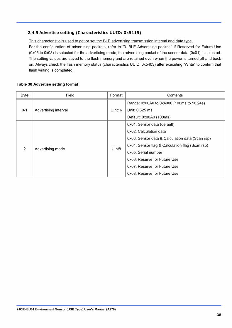
2.4.5 Advertise setting (Characteristics UUID: 0x5115)
This characteristic is used to get or set the BLE advertising transmission interval and data type. For the configuration of advertising packets, refer to "3. BLE Advertising packet." If Reserved for Future Use (0x06 to 0x08) is selected for the advertising mode, the advertising packet of the sensor data (0x01) is selected. The setting values are saved to the flash memory and are retained even when the power is turned off and back on. Always check the flash memory status (characteristics UUID: 0x5403) after executing "Write" to confirm that flash writing is completed.
Table 38 Advertise setting format
Byte Field Format Contents
0-1 Advertising interval UInt16
Range: 0x00A0 to 0x4000 (100ms to 10.24s)
Unit: 0.625 ms
Default: 0x00A0 (100ms)
2 Advertising mode UInt8
0x01: Sensor data (default)
0x02: Calculation data
0x03: Sensor data & Calculation data (Scan rsp)
0x04: Sensor flag & Calculation flag (Scan rsp)
0x05: Serial number
0x06: Reserve for Future Use
0x07: Reserve for Future Use
0x08: Reserve for Future Use
2JCIE-BU01 Environment Sensor (USB Type) User's Manual (A279) 39
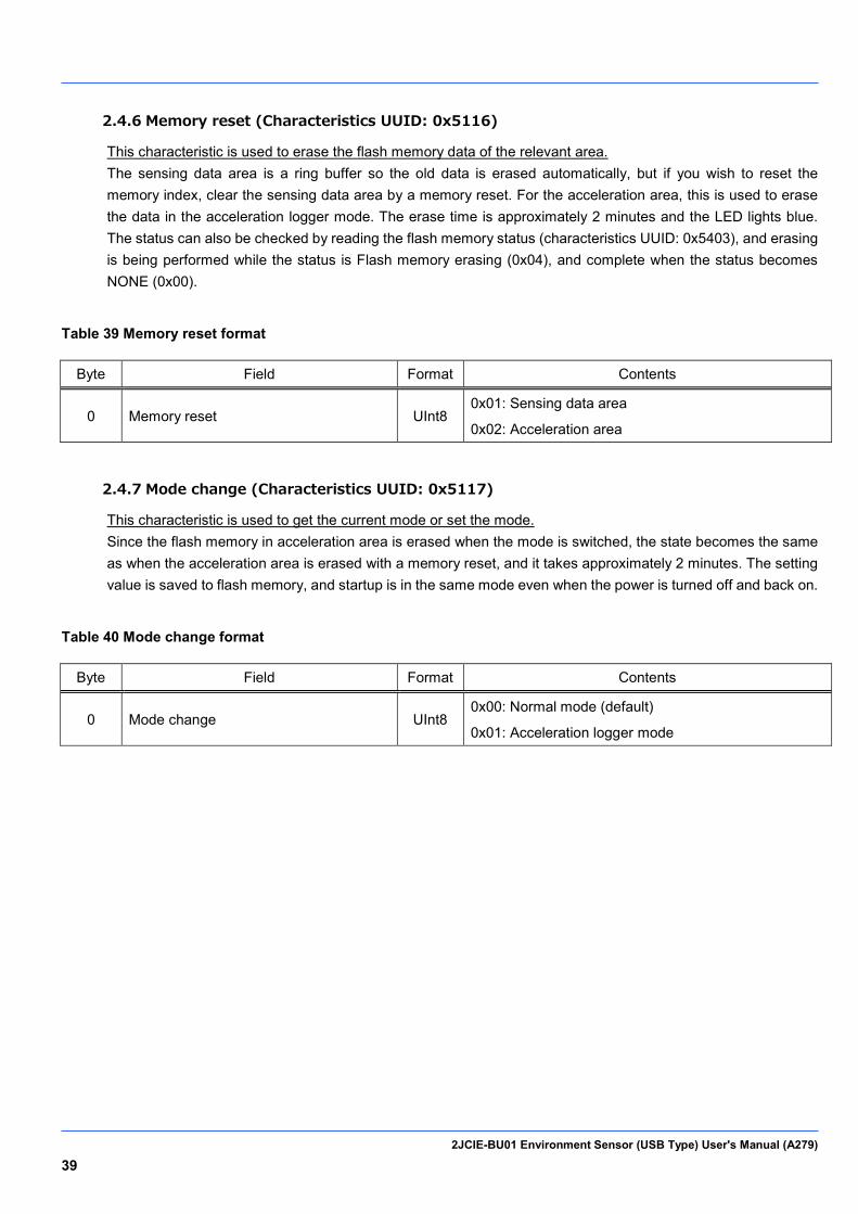
2.4.6 Memory reset (Characteristics UUID: 0x5116)
This characteristic is used to erase the flash memory data of the relevant area. The sensing data area is a ring buffer so the old data is erased automatically, but if you wish to reset the memory index, clear the sensing data area by a memory reset. For the acceleration area, this is used to erase the data in the acceleration logger mode. The erase time is approximately 2 minutes and the LED lights blue. The status can also be checked by reading the flash memory status (characteristics UUID: 0x5403), and erasing is being performed while the status is Flash memory erasing (0x04), and complete when the status becomes NONE (0x00).
Table 39 Memory reset format
Byte Field Format Contents
0 Memory reset UInt8 0x01: Sensing data area
0x02: Acceleration area
2.4.7 Mode change (Characteristics UUID: 0x5117)
This characteristic is used to get the current mode or set the mode. Since the flash memory in acceleration area is erased when the mode is switched, the state becomes the same as when the acceleration area is erased with a memory reset, and it takes approximately 2 minutes. The setting value is saved to flash memory, and startup is in the same mode even when the power is turned off and back on.
Table 40 Mode change format
Byte Field Format Contents
0 Mode change UInt8 0x00: Normal mode (default)
0x01: Acceleration logger mode
2JCIE-BU01 Environment Sensor (USB Type) User's Manual (A279) 40
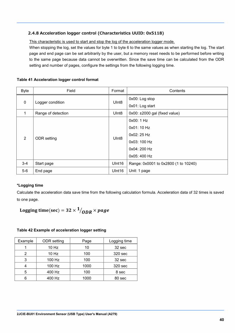
2.4.8 Acceleration logger control (Characteristics UUID: 0x5118)
This characteristic is used to start and stop the log of the acceleration logger mode. When stopping the log, set the values for byte 1 to byte 6 to the same values as when starting the log. The start page and end page can be set arbitrarily by the user, but a memory reset needs to be performed before writing to the same page because data cannot be overwritten. Since the save time can be calculated from the ODR setting and number of pages, configure the settings from the following logging time.
Table 41 Acceleration logger control format
Byte Field Format Contents
0 Logger condition UInt8 0x00: Log stop
0x01: Log start
1 Range of detection UInt8 0x00: ±2000 gal (fixed value)
2 ODR setting UInt8
0x00: 1 Hz
0x01: 10 Hz
0x02: 25 Hz
0x03: 100 Hz
0x04: 200 Hz
0x05: 400 Hz
3-4 Start page UInt16 Range: 0x0001 to 0x2800 (1 to 10240)
Unit: 1 page 5-6 End page UInt16
*Logging time
Calculate the acceleration data save time from the following calculation formula. Acceleration data of 32 times is saved
to one page.
𝐋𝐋𝐋𝐋𝐋𝐋𝐋 𝐭𝐋𝐭𝐭(𝐬𝐭𝐬) = 𝟑𝟑 × 𝟏𝑶𝑶𝑶� × 𝒑𝒑𝒑𝒑
Table 42 Example of acceleration logger setting
Example ODR setting Page Logging time 1 10 Hz 10 32 sec 2 10 Hz 100 320 sec 3 100 Hz 100 32 sec 4 100 Hz 1000 320 sec 5 400 Hz 100 8 sec 6 400 Hz 1000 80 sec
2JCIE-BU01 Environment Sensor (USB Type) User's Manual (A279) 41
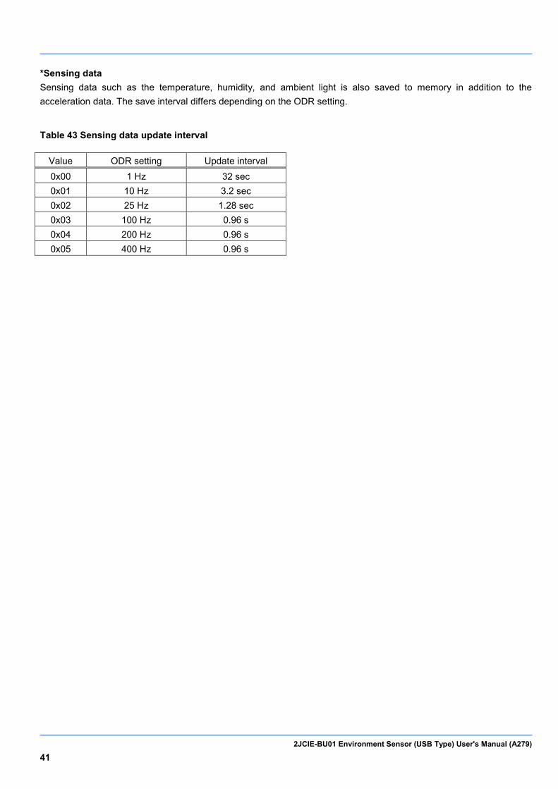
*Sensing data Sensing data such as the temperature, humidity, and ambient light is also saved to memory in addition to the acceleration data. The save interval differs depending on the ODR setting.
Table 43 Sensing data update interval
Value ODR setting Update interval 0x00 1 Hz 32 sec 0x01 10 Hz 3.2 sec 0x02 25 Hz 1.28 sec 0x03 100 Hz 0.96 s 0x04 200 Hz 0.96 s 0x05 400 Hz 0.96 s
2JCIE-BU01 Environment Sensor (USB Type) User's Manual (A279) 42
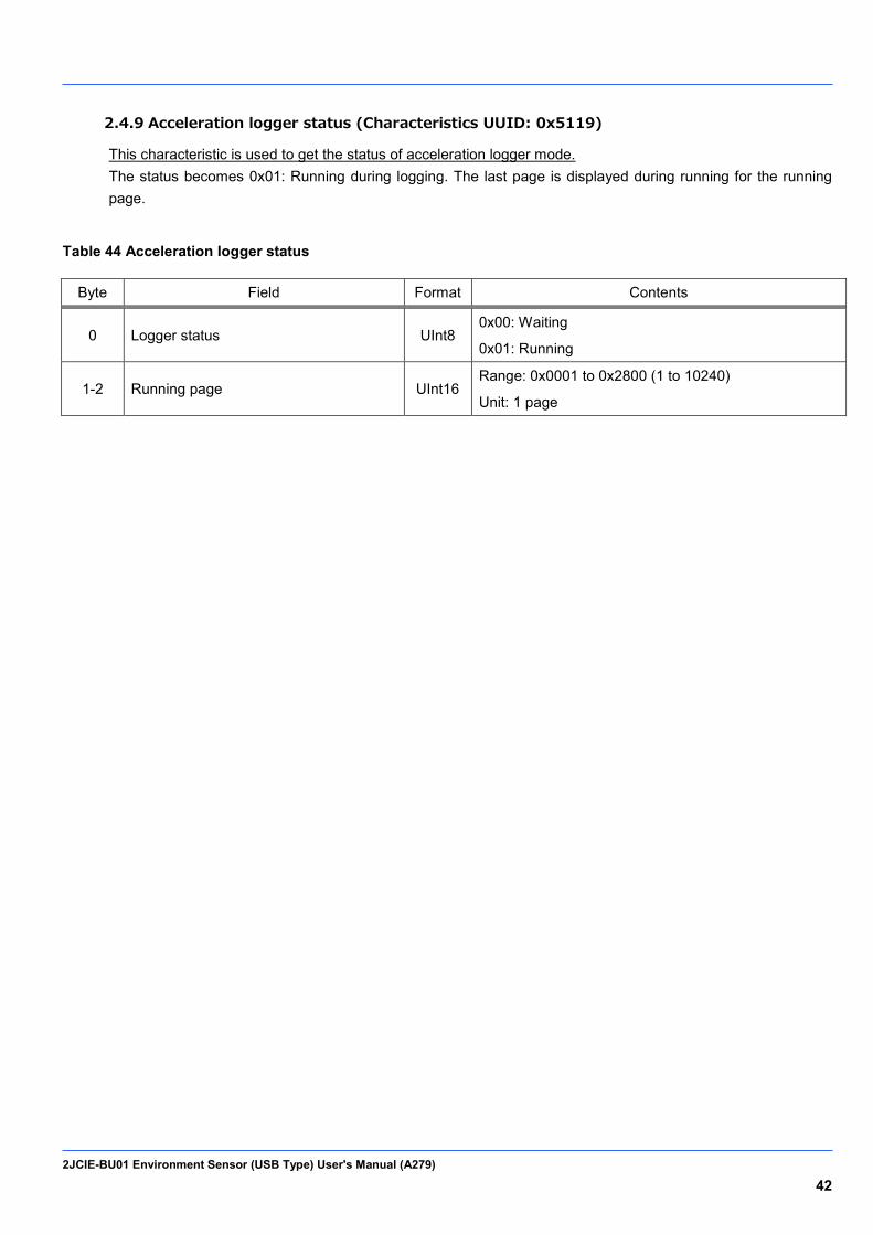
2.4.9 Acceleration logger status (Characteristics UUID: 0x5119)
This characteristic is used to get the status of acceleration logger mode. The status becomes 0x01: Running during logging. The last page is displayed during running for the running page.
Table 44 Acceleration logger status
Byte Field Format Contents
0 Logger status UInt8 0x00: Waiting
0x01: Running
1-2 Running page UInt16 Range: 0x0001 to 0x2800 (1 to 10240)
Unit: 1 page

2JCIE-BU01 Environment Sensor (USB Type) User's Manual (A279) 43
Time Setting Service (Service UUID: 0x5200) 2.5.
This service is used to configure settings related to time.
Table 45 List of Characteristics in Time Setting Service
UUID Characteristics Contents Properties
Byte R W N
0x5201 Time counter Value being counted by the device √ 8
0x5202 Time setting Count value that was set √ √ 8
0x5203 Memory storage interval Save interval for sensing data √ √ 2
2JCIE-BU01 Environment Sensor (USB Type) User's Manual (A279) 44
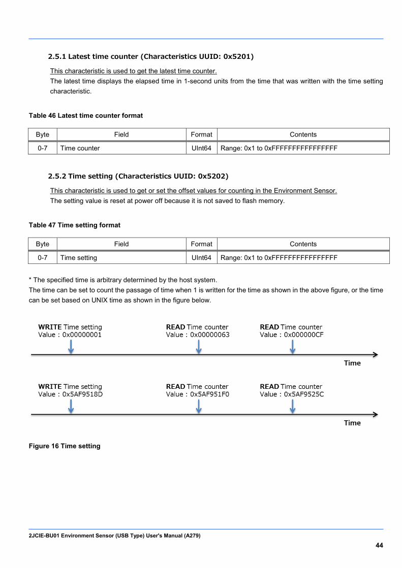
2.5.1 Latest time counter (Characteristics UUID: 0x5201)
This characteristic is used to get the latest time counter. The latest time displays the elapsed time in 1-second units from the time that was written with the time setting characteristic.
Table 46 Latest time counter format
Byte Field Format Contents
0-7 Time counter UInt64 Range: 0x1 to 0xFFFFFFFFFFFFFFFF
2.5.2 Time setting (Characteristics UUID: 0x5202)
This characteristic is used to get or set the offset values for counting in the Environment Sensor. The setting value is reset at power off because it is not saved to flash memory.
Table 47 Time setting format
Byte Field Format Contents
0-7 Time setting UInt64 Range: 0x1 to 0xFFFFFFFFFFFFFFFF
* The specified time is arbitrary determined by the host system. The time can be set to count the passage of time when 1 is written for the time as shown in the above figure, or the time can be set based on UNIX time as shown in the figure below.
Figure 16 Time setting

2JCIE-BU01 Environment Sensor (USB Type) User's Manual (A279) 45
2.5.3 Memory storage interval (Characteristics UUID: 0x5203)
This characteristic is used to get or set the interval to save the sensing data in flash memory. When the storage interval is changed, the memory index is reset and the flash memory in the sensing data area is also erased. The state becomes the same as when the sensing data area is erased with a memory reset, and it takes approximately 2 minutes. The setting values are saved to the flash memory and are retained even when the power is turned off and back on. Always check the flash memory status (characteristics UUID: 0x5403) after executing "Write" to confirm that flash writing is completed.
Table 48 Memory storage interval format
Byte Field Format Contents
0-1 Memory storage interval UInt16
Range: 0x0001 to 0x0E10 (1 to 3600sec)
Unit: 1sec
Default: 0x0001 (1sec)
2JCIE-BU01 Environment Sensor (USB Type) User's Manual (A279) 46
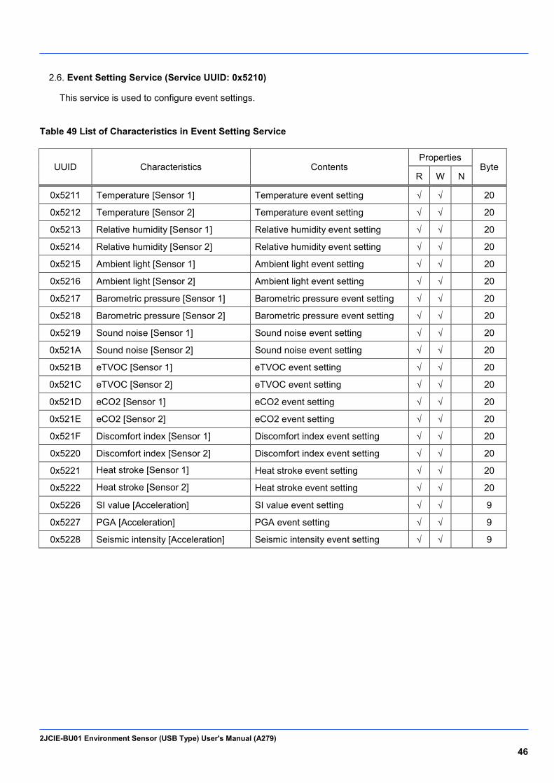
Event Setting Service (Service UUID: 0x5210) 2.6.
This service is used to configure event settings.
Table 49 List of Characteristics in Event Setting Service
UUID Characteristics Contents Properties
Byte R W N
0x5211 Temperature [Sensor 1] Temperature event setting √ √ 20
0x5212 Temperature [Sensor 2] Temperature event setting √ √ 20
0x5213 Relative humidity [Sensor 1] Relative humidity event setting √ √ 20
0x5214 Relative humidity [Sensor 2] Relative humidity event setting √ √ 20
0x5215 Ambient light [Sensor 1] Ambient light event setting √ √ 20
0x5216 Ambient light [Sensor 2] Ambient light event setting √ √ 20
0x5217 Barometric pressure [Sensor 1] Barometric pressure event setting √ √ 20
0x5218 Barometric pressure [Sensor 2] Barometric pressure event setting √ √ 20
0x5219 Sound noise [Sensor 1] Sound noise event setting √ √ 20
0x521A Sound noise [Sensor 2] Sound noise event setting √ √ 20
0x521B eTVOC [Sensor 1] eTVOC event setting √ √ 20
0x521C eTVOC [Sensor 2] eTVOC event setting √ √ 20
0x521D eCO2 [Sensor 1] eCO2 event setting √ √ 20
0x521E eCO2 [Sensor 2] eCO2 event setting √ √ 20
0x521F Discomfort index [Sensor 1] Discomfort index event setting √ √ 20
0x5220 Discomfort index [Sensor 2] Discomfort index event setting √ √ 20
0x5221 Heat stroke [Sensor 1] Heat stroke event setting √ √ 20
0x5222 Heat stroke [Sensor 2] Heat stroke event setting √ √ 20
0x5226 SI value [Acceleration] SI value event setting √ √ 9
0x5227 PGA [Acceleration] PGA event setting √ √ 9
0x5228 Seismic intensity [Acceleration] Seismic intensity event setting √ √ 9
2JCIE-BU01 Environment Sensor (USB Type) User's Manual (A279) 47
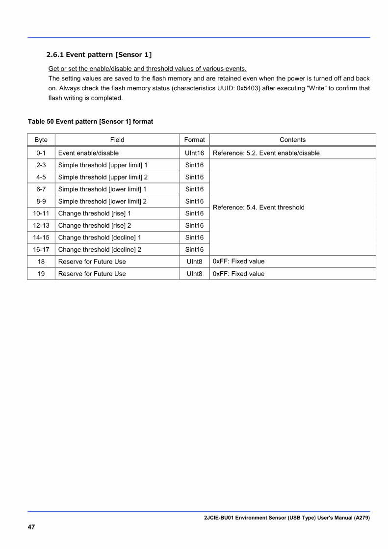
2.6.1 Event pattern [Sensor 1]
Get or set the enable/disable and threshold values of various events. The setting values are saved to the flash memory and are retained even when the power is turned off and back on. Always check the flash memory status (characteristics UUID: 0x5403) after executing "Write" to confirm that flash writing is completed.
Table 50 Event pattern [Sensor 1] format
Byte Field Format Contents
0-1 Event enable/disable UInt16 Reference: 5.2. Event enable/disable
2-3 Simple threshold [upper limit] 1 Sint16
Reference: 5.4. Event threshold
4-5 Simple threshold [upper limit] 2 Sint16
6-7 Simple threshold [lower limit] 1 Sint16
8-9 Simple threshold [lower limit] 2 Sint16
10-11 Change threshold [rise] 1 Sint16
12-13 Change threshold [rise] 2 Sint16
14-15 Change threshold [decline] 1 Sint16
16-17 Change threshold [decline] 2 Sint16
18 Reserve for Future Use UInt8 0xFF: Fixed value
19 Reserve for Future Use UInt8 0xFF: Fixed value
2JCIE-BU01 Environment Sensor (USB Type) User's Manual (A279) 48
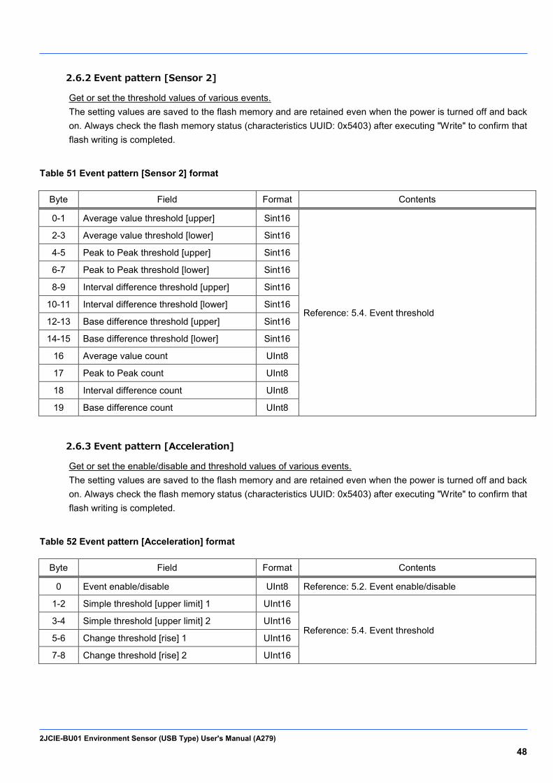
2.6.2 Event pattern [Sensor 2]
Get or set the threshold values of various events. The setting values are saved to the flash memory and are retained even when the power is turned off and back on. Always check the flash memory status (characteristics UUID: 0x5403) after executing "Write" to confirm that flash writing is completed.
Table 51 Event pattern [Sensor 2] format
Byte Field Format Contents
0-1 Average value threshold [upper] Sint16
Reference: 5.4. Event threshold
2-3 Average value threshold [lower] Sint16
4-5 Peak to Peak threshold [upper] Sint16
6-7 Peak to Peak threshold [lower] Sint16
8-9 Interval difference threshold [upper] Sint16
10-11 Interval difference threshold [lower] Sint16
12-13 Base difference threshold [upper] Sint16
14-15 Base difference threshold [lower] Sint16
16 Average value count UInt8
17 Peak to Peak count UInt8
18 Interval difference count UInt8
19 Base difference count UInt8
2.6.3 Event pattern [Acceleration]
Get or set the enable/disable and threshold values of various events. The setting values are saved to the flash memory and are retained even when the power is turned off and back on. Always check the flash memory status (characteristics UUID: 0x5403) after executing "Write" to confirm that flash writing is completed.
Table 52 Event pattern [Acceleration] format
Byte Field Format Contents
0 Event enable/disable UInt8 Reference: 5.2. Event enable/disable
1-2 Simple threshold [upper limit] 1 UInt16
Reference: 5.4. Event threshold 3-4 Simple threshold [upper limit] 2 UInt16
5-6 Change threshold [rise] 1 UInt16
7-8 Change threshold [rise] 2 UInt16
2JCIE-BU01 Environment Sensor (USB Type) User's Manual (A279) 49
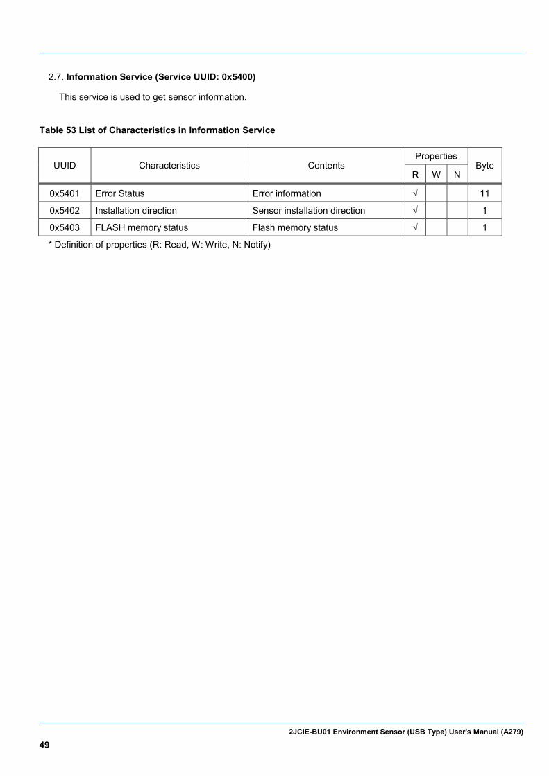
Information Service (Service UUID: 0x5400) 2.7.
This service is used to get sensor information.
Table 53 List of Characteristics in Information Service
UUID Characteristics Contents Properties
Byte R W N
0x5401 Error Status Error information √
11
0x5402 Installation direction Sensor installation direction √
1
0x5403 FLASH memory status Flash memory status √
1
* Definition of properties (R: Read, W: Write, N: Notify)

2JCIE-BU01 Environment Sensor (USB Type) User's Manual (A279) 50
2.7.1 Error status (Characteristics UUID: 0x5401)
This characteristic is used to get the error status of the sensors and CPU. The error status is cleared when this is read from the other device.
Table 54 Error status format
Byte Field Format Contents
0 Temperature sensor error UInt8
Bit3: Initialization error Bit2: Frozen output Bit1: Sensing data is out of range Bit0: Communication error
1 Relative humidity sensor error UInt8
2 Ambient light sensor error UInt8
3 Barometric pressure sensor error UInt8
4 Sound noise sensor error UInt8
5 Acceleration sensor error UInt8
6 eTVOC sensor error UInt8
7 eCO2 sensor error UInt8
8 CPU error UInt8
Bit2: Reboot with watchdog
Bit1: FLASH memory erase error
Bit0: FLASH memory initialization error
9 Reserve for Future Use UInt8 0xFF: Fixed value
10 Reserve for Future Use UInt8 0xFF: Fixed value
2JCIE-BU01 Environment Sensor (USB Type) User's Manual (A279) 51
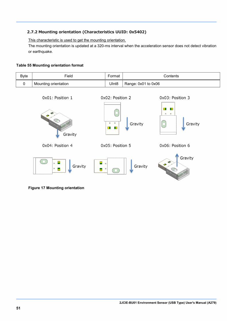
2.7.2 Mounting orientation (Characteristics UUID: 0x5402)
This characteristic is used to get the mounting orientation. The mounting orientation is updated at a 320-ms interval when the acceleration sensor does not detect vibration or earthquake.
Table 55 Mounting orientation format
Byte Field Format Contents
0 Mounting orientation UInt8 Range: 0x01 to 0x06
Figure 17 Mounting orientation
2JCIE-BU01 Environment Sensor (USB Type) User's Manual (A279) 52
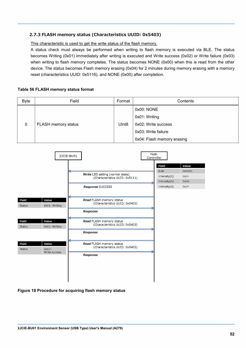
2.7.3 FLASH memory status (Characteristics UUID: 0x5403)
This characteristic is used to get the write status of the flash memory. A status check must always be performed when writing to flash memory is executed via BLE. The status becomes Writing (0x01) immediately after writing is executed and Write success (0x02) or Write failure (0x03) when writing to flash memory completes. The status becomes NONE (0x00) when this is read from the other device. The status becomes Flash memory erasing (0x04) for 2 minutes during memory erasing with a memory reset (characteristics UUID: 0x5116), and NONE (0x00) after completion.
Table 56 FLASH memory status format
Byte Field Format Contents
0 FLASH memory status UInt8
0x00: NONE
0x01: Writing
0x02: Write success
0x03: Write failure
0x04: Flash memory erasing
Figure 18 Procedure for acquiring flash memory status

2JCIE-BU01 Environment Sensor (USB Type) User's Manual (A279) 53
Generic Access Service (Service UUID: 0x1800) 2.8.
Table 57 List of Characteristics in Generic Access Service
UUID Characteristics Contents Properties
Byte R W N
0x2A00 Device name Name √ 10
0x2A01 Appearance Category √
2
0x2A04 Peripheral preferred connection parameters
Minimum connection interval
√ 2
Maximum connection interval
√ 2
Slave latency √ 2
Connection supervision timeout multiplier
√ 2
0x2AA6 Central address resolution Central address resolution support
√ 1
2JCIE-BU01 Environment Sensor (USB Type) User's Manual (A279) 54
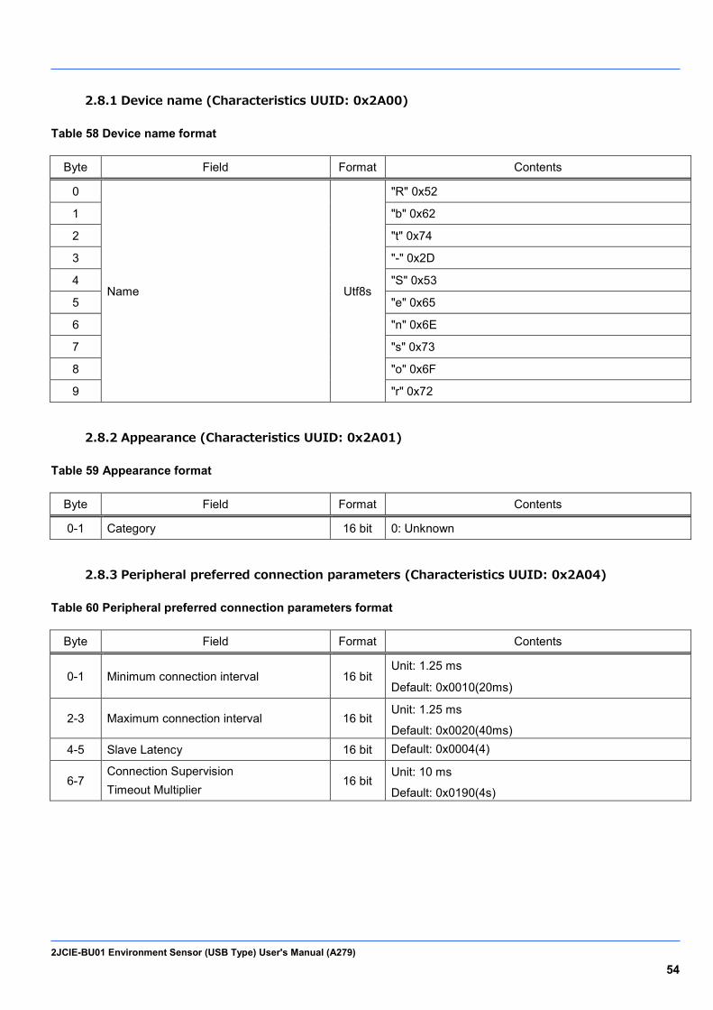
2.8.1 Device name (Characteristics UUID: 0x2A00)
Table 58 Device name format
Byte Field Format Contents
0
Name Utf8s
"R" 0x52
1 "b" 0x62
2 "t" 0x74
3 "-" 0x2D
4 "S" 0x53
5 "e" 0x65
6 "n" 0x6E
7 "s" 0x73
8 "o" 0x6F
9 "r" 0x72
2.8.2 Appearance (Characteristics UUID: 0x2A01)
Table 59 Appearance format
Byte Field Format Contents
0-1 Category 16 bit 0: Unknown
2.8.3 Peripheral preferred connection parameters (Characteristics UUID: 0x2A04)
Table 60 Peripheral preferred connection parameters format
Byte Field Format Contents
0-1 Minimum connection interval 16 bit Unit: 1.25 ms
Default: 0x0010(20ms)
2-3 Maximum connection interval 16 bit Unit: 1.25 ms
Default: 0x0020(40ms) 4-5 Slave Latency 16 bit Default: 0x0004(4)
6-7 Connection Supervision Timeout Multiplier
16 bit Unit: 10 ms
Default: 0x0190(4s)

2JCIE-BU01 Environment Sensor (USB Type) User's Manual (A279) 55
2.8.4 Central address resolution (Characteristics UUID: 0x2AA6)
Table 61 Central address resolution support format
Byte Field Format Contents
0 Central address resolution support
UInt8 1: Address resolution is supported in this device

2JCIE-BU01 Environment Sensor (USB Type) User's Manual (A279) 56
Device Information Service (Service UUID: 0x180A) 2.9.
Table 62 List of Characteristics in Generic Access Service
UUID Characteristics Contents Properties
Byte R W N
0x2A24 Model Number String Model Number √ 10
0x2A25 Serial Number String Serial Number √
10
0x2A26 Firmware Revision String Firmware Revision √ 5
0x2A27 Hardware Revision String Hardware Revision √ 5
0x2A29 Manufacturer Name String Manufacturer Name √ 5
2JCIE-BU01 Environment Sensor (USB Type) User's Manual (A279) 57
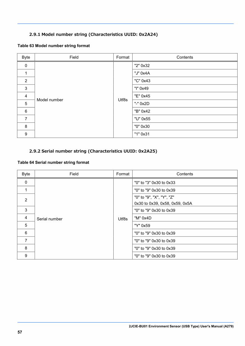
2.9.1 Model number string (Characteristics UUID: 0x2A24)
Table 63 Model number string format
Byte Field Format Contents
0
Model number Utf8s
"2" 0x32
1 "J" 0x4A
2 "C" 0x43
3 "I" 0x49
4 "E" 0x45
5 "-" 0x2D
6 "B" 0x42
7 "U" 0x55
8 "0" 0x30
9 "1" 0x31
2.9.2 Serial number string (Characteristics UUID: 0x2A25)
Table 64 Serial number string format
Byte Field Format Contents
0
Serial number Utf8s
"0" to "3" 0x30 to 0x33
1 "0" to "9" 0x30 to 0x39
2 "0" to "9", "X", "Y", "Z" 0x30 to 0x39, 0x58, 0x59, 0x5A
3 "0" to "9" 0x30 to 0x39
4 "M" 0x4D
5 "Y" 0x59
6 "0" to "9" 0x30 to 0x39
7 "0" to "9" 0x30 to 0x39
8 "0" to "9" 0x30 to 0x39
9 "0" to "9" 0x30 to 0x39

2JCIE-BU01 Environment Sensor (USB Type) User's Manual (A279) 58
2.9.3 Firmware revision string (Characteristics UUID: 0x2A26)
Table 65 Firmware revision string format
Byte Field Format Contents
0
Firmware revision Utf8s
"0" to "9" 0x30 to 0x39
1 "0" to "9" 0x30 to 0x39
2 "." 0x2E
3 "0" to "9" 0x30 to 0x39
4 "0" to "9" 0x30 to 0x39
2.9.4 Hardware revision string (Characteristics UUID: 0x2A27)
Table 66 Hardware revision string format
Byte Field Format Contents
0
Hardware revision Utf8s
"0" to "9" 0x30 to 0x39
1 "0" to "9" 0x30 to 0x39
2 "." 0x2E
3 "0" to "9" 0x30 to 0x39
4 "0" to "9" 0x30 to 0x39
2.9.5 Manufacturer name string (Characteristics UUID: 0x2A28)
Table 67 Manufacture name string format
Byte Field Format Contents
0
Manufacture name Utf8s
"O" 0x4F
1 "M" 0x4D
2 "R" 0x52
3 "O" 0x4F
4 "N" 0x4E
2JCIE-BU01 Environment Sensor (USB Type) User's Manual (A279) 59
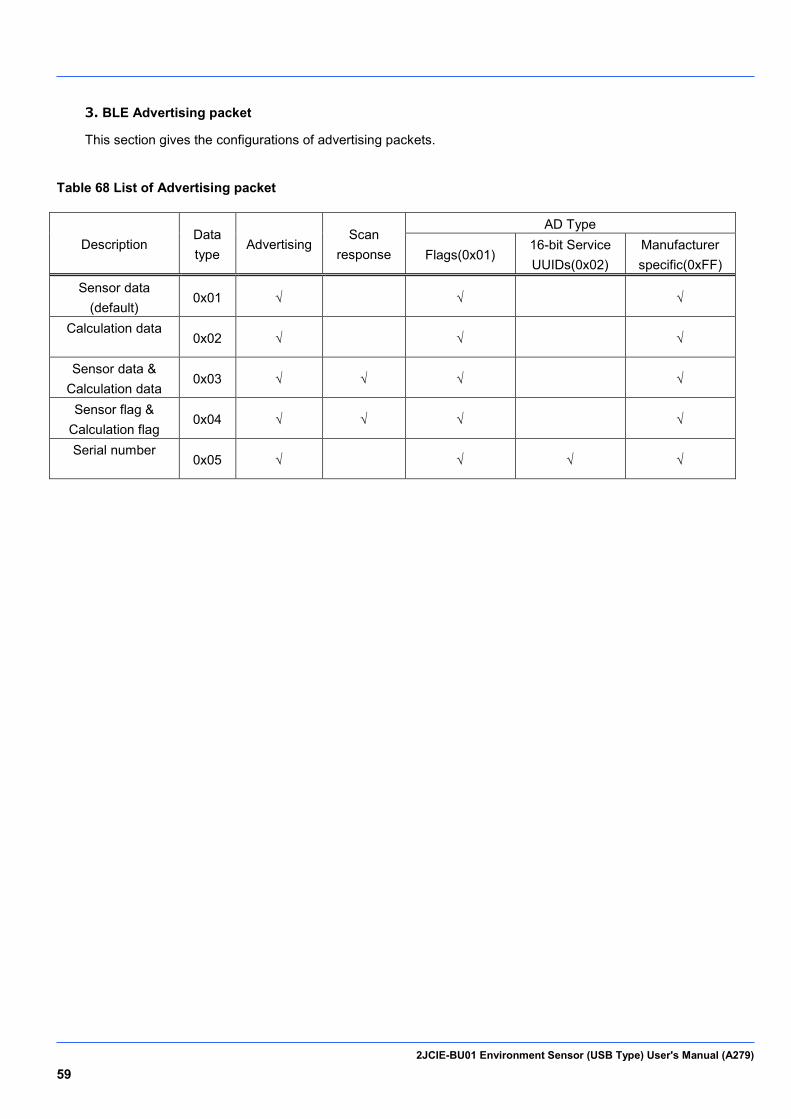
3. BLE Advertising packet
This section gives the configurations of advertising packets.
Table 68 List of Advertising packet
Description Data type
Advertising Scan
response
AD Type
Flags(0x01) 16-bit Service UUIDs(0x02)
Manufacturer specific(0xFF)
Sensor data (default)
0x01 √ √ √
Calculation data
0x02 √ √ √
Sensor data & Calculation data
0x03 √ √ √ √
Sensor flag & Calculation flag
0x04 √ √ √ √
Serial number
0x05 √ √ √ √
2JCIE-BU01 Environment Sensor (USB Type) User's Manual (A279) 60
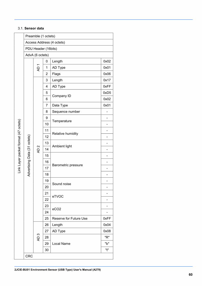
Sensor data 3.1.
Link
Lay
er p
acke
t for
mat
(47
octe
ts)
Preamble (1 octets)
Access Address (4 octets)
PDU Header (16bits)
AdvA (6 octets)
Adve
rtisi
ng D
ata
(31
octe
ts)
AD 1
0 Length 0x02
1 AD Type 0x01
2 Flags 0x06
AD 2
3 Length 0x17
4 AD Type 0xFF
5 Company ID
0xD5
6 0x02
7 Data Type 0x01
8 Sequence number -
9 Temperature
-
10 -
11 Relative humidity
-
12 -
13 Ambient light
-
14 -
15
Barometric pressure
-
16 -
17 -
18 -
19 Sound noise
-
20 -
21 eTVOC
-
22 -
23 eCO2
-
24 -
25 Reserve for Future Use 0xFF
AD 3
26 Length 0x04
27 AD Type 0x08
28
Local Name
"R"
29 "b"
30 "t"
CRC
2JCIE-BU01 Environment Sensor (USB Type) User's Manual (A279) 61
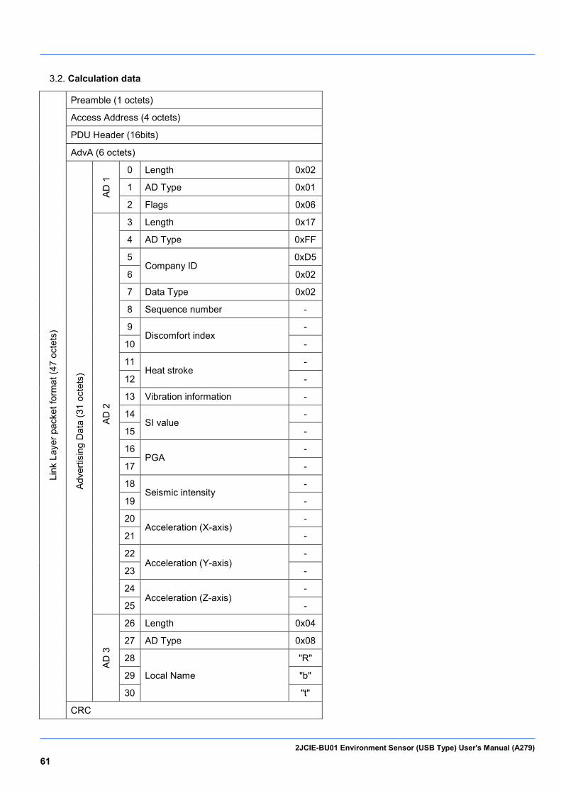
Calculation data 3.2.
Link
Lay
er p
acke
t for
mat
(47
octe
ts)
Preamble (1 octets)
Access Address (4 octets)
PDU Header (16bits)
AdvA (6 octets)
Adve
rtisi
ng D
ata
(31
octe
ts)
AD 1
0 Length 0x02
1 AD Type 0x01
2 Flags 0x06
AD 2
3 Length 0x17
4 AD Type 0xFF
5 Company ID
0xD5
6 0x02
7 Data Type 0x02
8 Sequence number -
9 Discomfort index
-
10 -
11 Heat stroke
-
12 -
13 Vibration information -
14 SI value
-
15 -
16 PGA
-
17 -
18 Seismic intensity
-
19 -
20 Acceleration (X-axis)
-
21 -
22 Acceleration (Y-axis)
-
23 -
24 Acceleration (Z-axis)
-
25 -
AD 3
26 Length 0x04
27 AD Type 0x08
28
Local Name
"R"
29 "b"
30 "t"
CRC
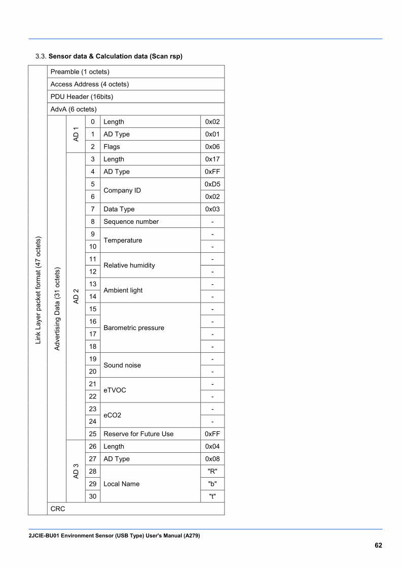
2JCIE-BU01 Environment Sensor (USB Type) User's Manual (A279) 62
Sensor data & Calculation data (Scan rsp) 3.3.
Link
Lay
er p
acke
t for
mat
(47
octe
ts)
Preamble (1 octets)
Access Address (4 octets)
PDU Header (16bits)
AdvA (6 octets)
Adve
rtisi
ng D
ata
(31
octe
ts)
AD 1
0 Length 0x02
1 AD Type 0x01
2 Flags 0x06
AD 2
3 Length 0x17
4 AD Type 0xFF
5 Company ID
0xD5
6 0x02
7 Data Type 0x03
8 Sequence number -
9 Temperature
-
10 -
11 Relative humidity
-
12 -
13 Ambient light
-
14 -
15
Barometric pressure
-
16 -
17 -
18 -
19 Sound noise
-
20 -
21 eTVOC
-
22 -
23 eCO2
-
24 -
25 Reserve for Future Use 0xFF
AD 3
26 Length 0x04
27 AD Type 0x08
28
Local Name
"R"
29 "b"
30 "t"
CRC
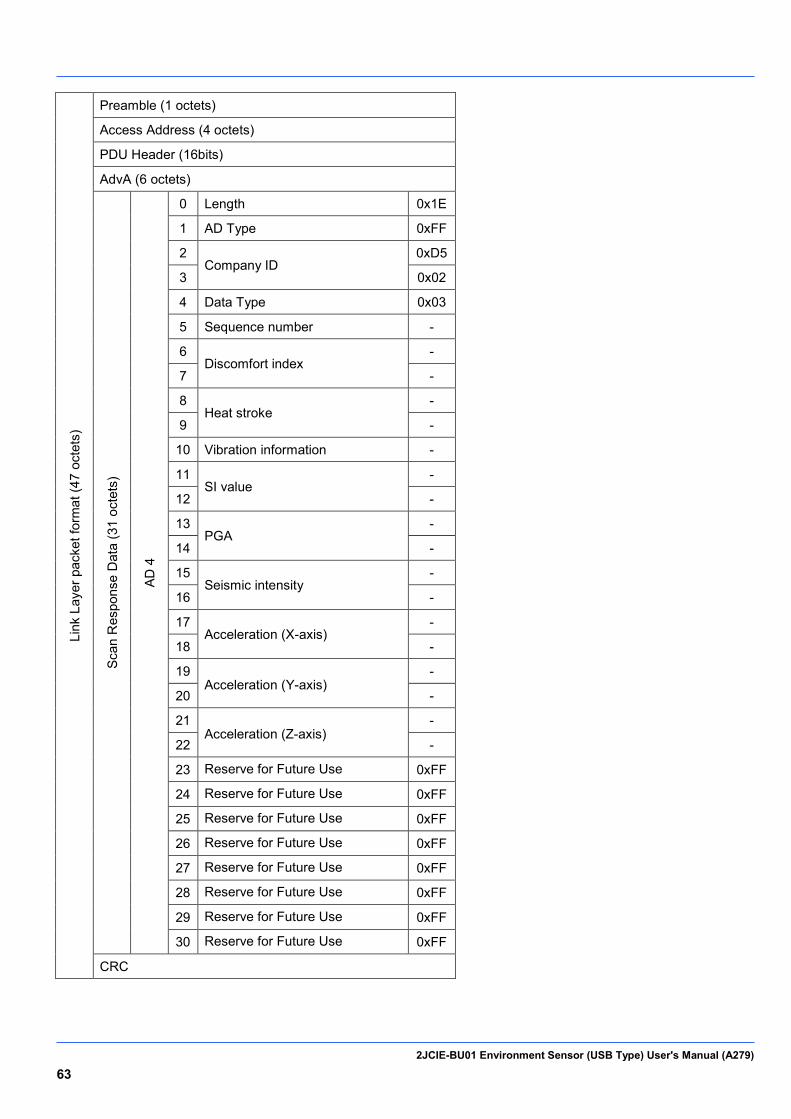
2JCIE-BU01 Environment Sensor (USB Type) User's Manual (A279) 63
Link
Lay
er p
acke
t for
mat
(47
octe
ts)
Preamble (1 octets)
Access Address (4 octets)
PDU Header (16bits)
AdvA (6 octets)
Scan
Res
pons
e D
ata
(31
octe
ts)
AD 4
0 Length 0x1E
1 AD Type 0xFF
2 Company ID
0xD5
3 0x02
4 Data Type 0x03
5 Sequence number -
6 Discomfort index
-
7 -
8 Heat stroke
-
9 -
10 Vibration information -
11 SI value
-
12 -
13 PGA
-
14 -
15 Seismic intensity
-
16 -
17 Acceleration (X-axis)
-
18 -
19 Acceleration (Y-axis)
-
20 -
21 Acceleration (Z-axis)
-
22 -
23 Reserve for Future Use 0xFF
24 Reserve for Future Use 0xFF
25 Reserve for Future Use 0xFF
26 Reserve for Future Use 0xFF
27 Reserve for Future Use 0xFF
28 Reserve for Future Use 0xFF
29 Reserve for Future Use 0xFF
30 Reserve for Future Use 0xFF
CRC
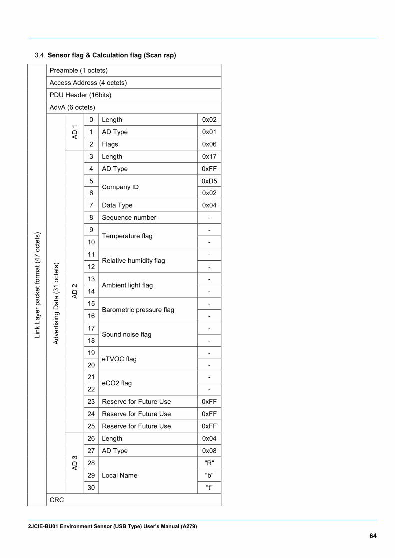
2JCIE-BU01 Environment Sensor (USB Type) User's Manual (A279) 64
Sensor flag & Calculation flag (Scan rsp) 3.4.
Link
Lay
er p
acke
t for
mat
(47
octe
ts)
Preamble (1 octets)
Access Address (4 octets)
PDU Header (16bits)
AdvA (6 octets)
Adve
rtisi
ng D
ata
(31
octe
ts)
AD 1
0 Length 0x02
1 AD Type 0x01
2 Flags 0x06
AD 2
3 Length 0x17
4 AD Type 0xFF
5 Company ID
0xD5
6 0x02
7 Data Type 0x04
8 Sequence number -
9 Temperature flag
-
10 -
11 Relative humidity flag
-
12 -
13 Ambient light flag
-
14 -
15 Barometric pressure flag
-
16 -
17 Sound noise flag
-
18 -
19 eTVOC flag
-
20 -
21 eCO2 flag
-
22 -
23 Reserve for Future Use 0xFF
24 Reserve for Future Use 0xFF
25 Reserve for Future Use 0xFF
AD 3
26 Length 0x04
27 AD Type 0x08
28
Local Name
"R"
29 "b"
30 "t"
CRC

2JCIE-BU01 Environment Sensor (USB Type) User's Manual (A279) 65
Link
Lay
er p
acke
t for
mat
(47
octe
ts)
Preamble (1 octets)
Access Address (4 octets)
PDU Header (16bits)
AdvA (6 octets)
Scan
Res
pons
e D
ata
(31
octe
ts)
AD 4
0 Length 0x1E
1 AD Type 0xFF
2 Company ID
0xD5
3 0x02
4 Data Type 0x04
5 Sequence Number -
6 Discomfort index flag
-
7 -
8 Heat stroke flag
-
9 -
10 SI value flag -
11 PGA flag -
12 Seismic intensity flag -
13 Reserve for Future Use 0xFF
14 Reserve for Future Use 0xFF
15 Reserve for Future Use 0xFF
16 Reserve for Future Use 0xFF
17 Reserve for Future Use 0xFF
18 Reserve for Future Use 0xFF
19 Reserve for Future Use 0xFF
20 Reserve for Future Use 0xFF
21 Reserve for Future Use 0xFF
22 Reserve for Future Use 0xFF
23 Reserve for Future Use 0xFF
24 Reserve for Future Use 0xFF
25 Reserve for Future Use 0xFF
26 Reserve for Future Use 0xFF
27 Reserve for Future Use 0xFF
28 Reserve for Future Use 0xFF
29 Reserve for Future Use 0xFF
30 Reserve for Future Use 0xFF
CRC
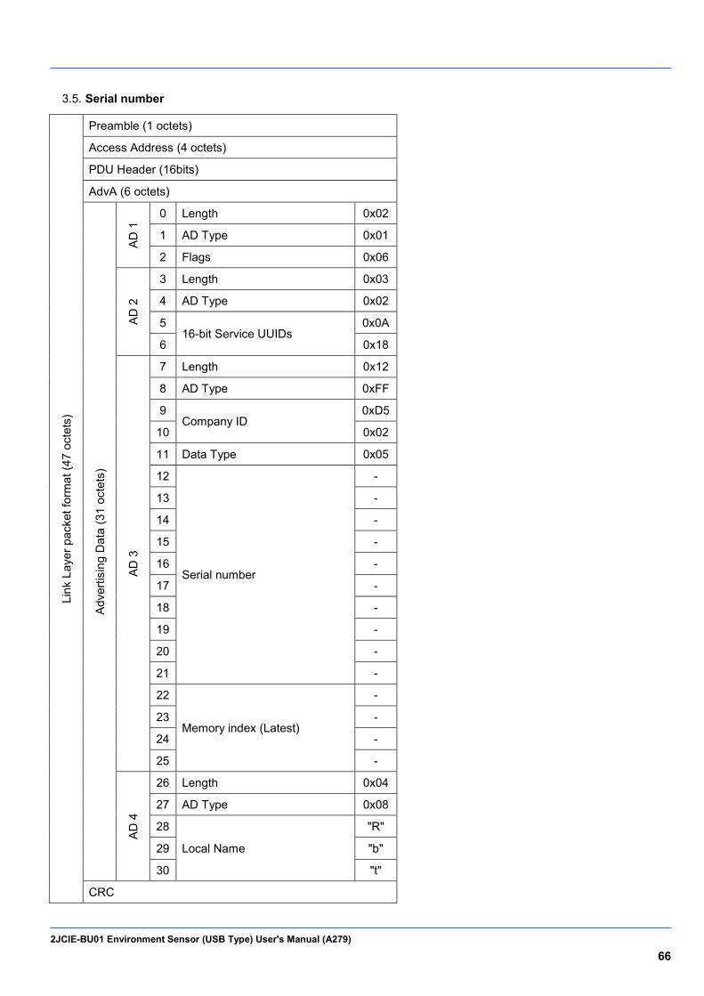
2JCIE-BU01 Environment Sensor (USB Type) User's Manual (A279) 66
Serial number 3.5.
Link
Lay
er p
acke
t for
mat
(47
octe
ts)
Preamble (1 octets)
Access Address (4 octets)
PDU Header (16bits)
AdvA (6 octets)
Adve
rtisi
ng D
ata
(31
octe
ts)
AD 1
0 Length 0x02
1 AD Type 0x01
2 Flags 0x06
AD 2
3 Length 0x03
4 AD Type 0x02
5 16-bit Service UUIDs
0x0A
6 0x18
AD 3
7 Length 0x12
8 AD Type 0xFF
9 Company ID
0xD5
10 0x02
11 Data Type 0x05
12
Serial number
-
13 -
14 -
15 -
16 -
17 -
18 -
19 -
20 -
21 -
22
Memory index (Latest)
-
23 -
24 -
25 -
AD 4
26 Length 0x04
27 AD Type 0x08
28
Local Name
"R"
29 "b"
30 "t"
CRC
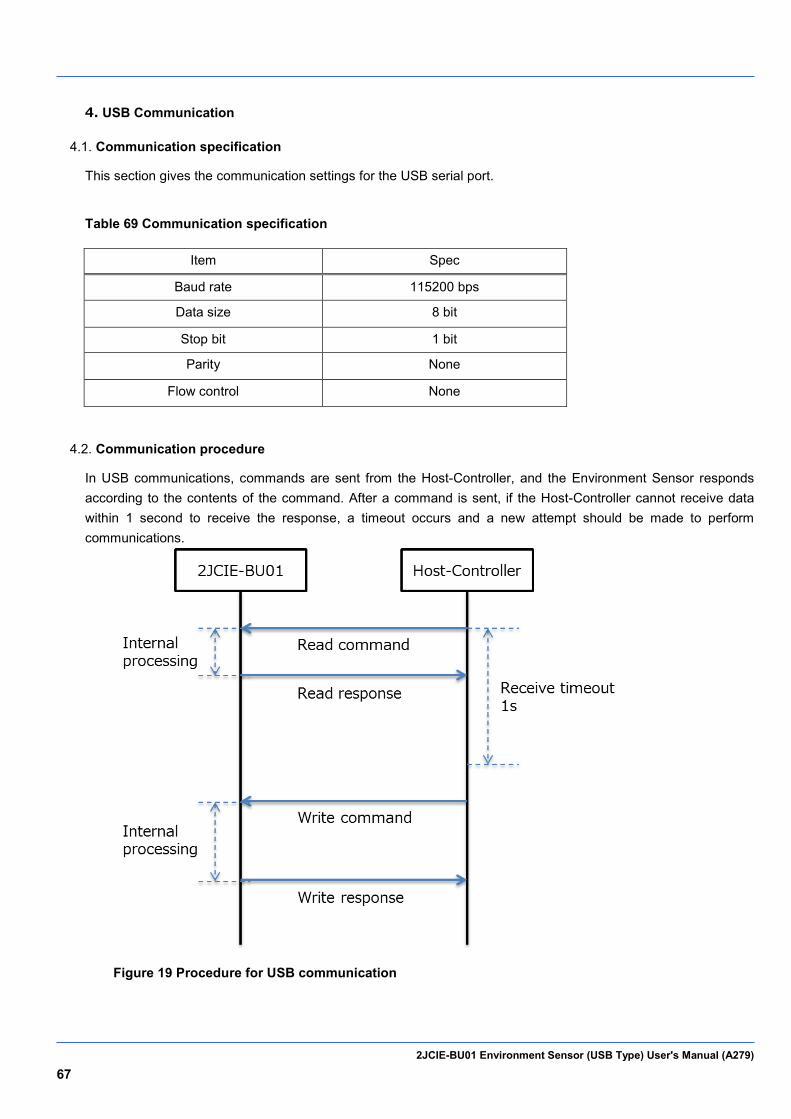
2JCIE-BU01 Environment Sensor (USB Type) User's Manual (A279) 67
4. USB Communication
Communication specification 4.1.
This section gives the communication settings for the USB serial port.
Table 69 Communication specification
Item Spec
Baud rate 115200 bps
Data size 8 bit
Stop bit 1 bit
Parity None
Flow control None
Communication procedure 4.2.
In USB communications, commands are sent from the Host-Controller, and the Environment Sensor responds according to the contents of the command. After a command is sent, if the Host-Controller cannot receive data within 1 second to receive the response, a timeout occurs and a new attempt should be made to perform communications.
Figure 19 Procedure for USB communication
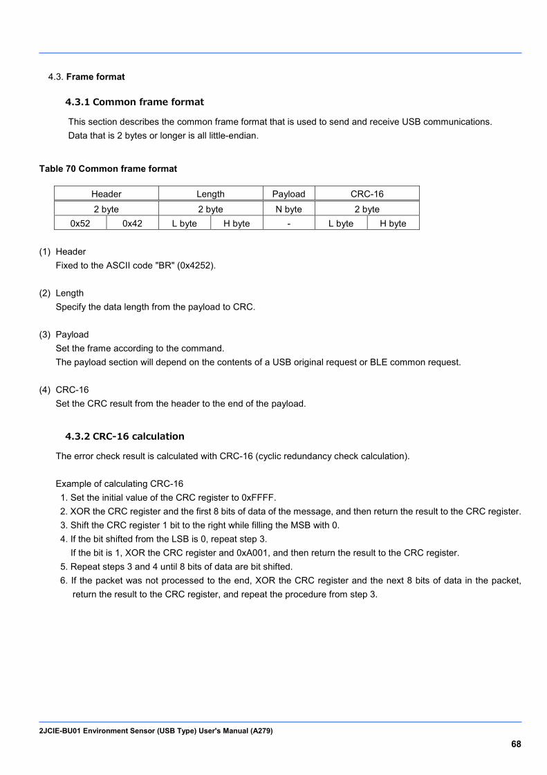
2JCIE-BU01 Environment Sensor (USB Type) User's Manual (A279) 68
Frame format 4.3.
4.3.1 Common frame format
This section describes the common frame format that is used to send and receive USB communications. Data that is 2 bytes or longer is all little-endian.
Table 70 Common frame format
Header Length Payload CRC-16 2 byte 2 byte N byte 2 byte
0x52 0x42 L byte H byte - L byte H byte (1) Header
Fixed to the ASCII code "BR" (0x4252). (2) Length
Specify the data length from the payload to CRC. (3) Payload
Set the frame according to the command. The payload section will depend on the contents of a USB original request or BLE common request.
(4) CRC-16
Set the CRC result from the header to the end of the payload.
4.3.2 CRC-16 calculation
The error check result is calculated with CRC-16 (cyclic redundancy check calculation). Example of calculating CRC-16 1. Set the initial value of the CRC register to 0xFFFF. 2. XOR the CRC register and the first 8 bits of data of the message, and then return the result to the CRC register. 3. Shift the CRC register 1 bit to the right while filling the MSB with 0. 4. If the bit shifted from the LSB is 0, repeat step 3.
If the bit is 1, XOR the CRC register and 0xA001, and then return the result to the CRC register. 5. Repeat steps 3 and 4 until 8 bits of data are bit shifted. 6. If the packet was not processed to the end, XOR the CRC register and the next 8 bits of data in the packet,
return the result to the CRC register, and repeat the procedure from step 3.
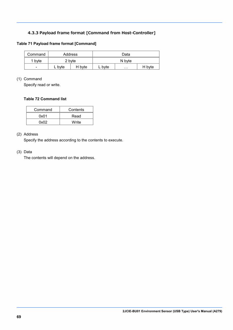
2JCIE-BU01 Environment Sensor (USB Type) User's Manual (A279) 69
4.3.3 Payload frame format [Command from Host-Controller]
Table 71 Payload frame format [Command]
Command Address Data 1 byte 2 byte N byte
- L byte H byte L byte … H byte (1) Command
Specify read or write.
Table 72 Command list
Command Contents 0x01 Read 0x02 Write
(2) Address
Specify the address according to the contents to execute. (3) Data
The contents will depend on the address.

2JCIE-BU01 Environment Sensor (USB Type) User's Manual (A279) 70
4.3.4 Payload frame format [Normal Response from 2JCIE-BU01]
Table 73 Payload frame format [Response]
Command Address Data 1 byte 2 byte N byte
- L byte H byte L byte … H byte (1) Command
Return the results of the read or write.
Table 74 Command list
Command Contents 0x01 Read 0x02 Write
(2) Address
Specify the address specified with the command. (3) Data
The contents will depend on the address.

2JCIE-BU01 Environment Sensor (USB Type) User's Manual (A279) 71
4.3.5 Payload frame format [Error Response from 2JCIE-BU01]
Table 75 Payload frame format [Response]
Command Address Code 1 byte 2 byte 1 byte
- L byte H byte - (1) Command
Return the results of the read or write. When an error is returned from the Environment Sensor, the MSB of the command is set to 1 (in other words, 0x80 is added to the value of the non-error command). When a command other than a read or write command is received, Unknown (0xFF) is returned.
Table 76 Command list
Command Contents 0x81 Read error 0x82 Write error 0xFF Unknown
(2) Address
Specify the address according to the contents to execute. (3) Code
Return the details of the error.
Table 77 Error code
Code Description Contents 0x01 CRC error When the CRC-16 calculation is incorrect
0x02 Command error When other than read or write is specified for the command In this case, the error for the command becomes Unknown.
0x03 Address error When an address not contained in the address list is specified 0x04 Length error When the length specified in the address is incorrect 0x05 Data error When outside of the write range of Write is specified
0x06 Busy When performing internal processing such as during flash memory access
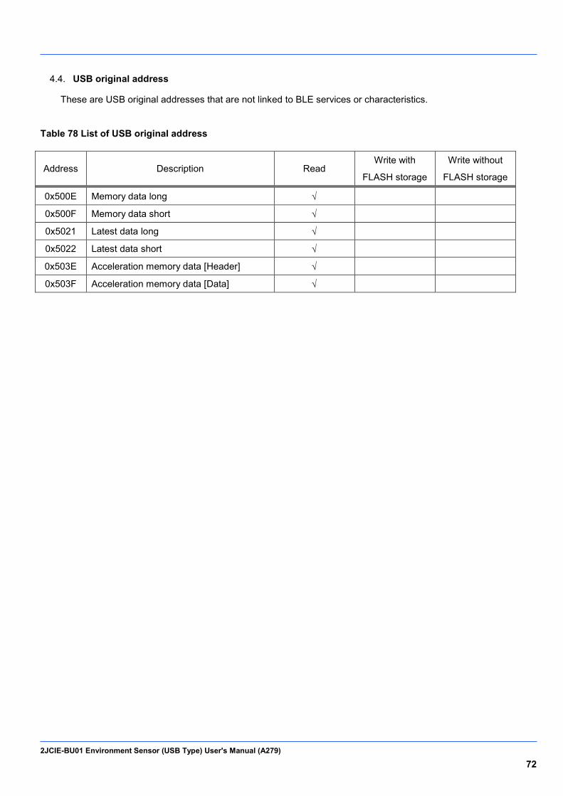
2JCIE-BU01 Environment Sensor (USB Type) User's Manual (A279) 72
USB original address 4.4.
These are USB original addresses that are not linked to BLE services or characteristics.
Table 78 List of USB original address
Address Description Read Write with
FLASH storage
Write without
FLASH storage
0x500E Memory data long √
0x500F Memory data short √
0x5021 Latest data long √
0x5022 Latest data short √
0x503E Acceleration memory data [Header] √
0x503F Acceleration memory data [Data] √
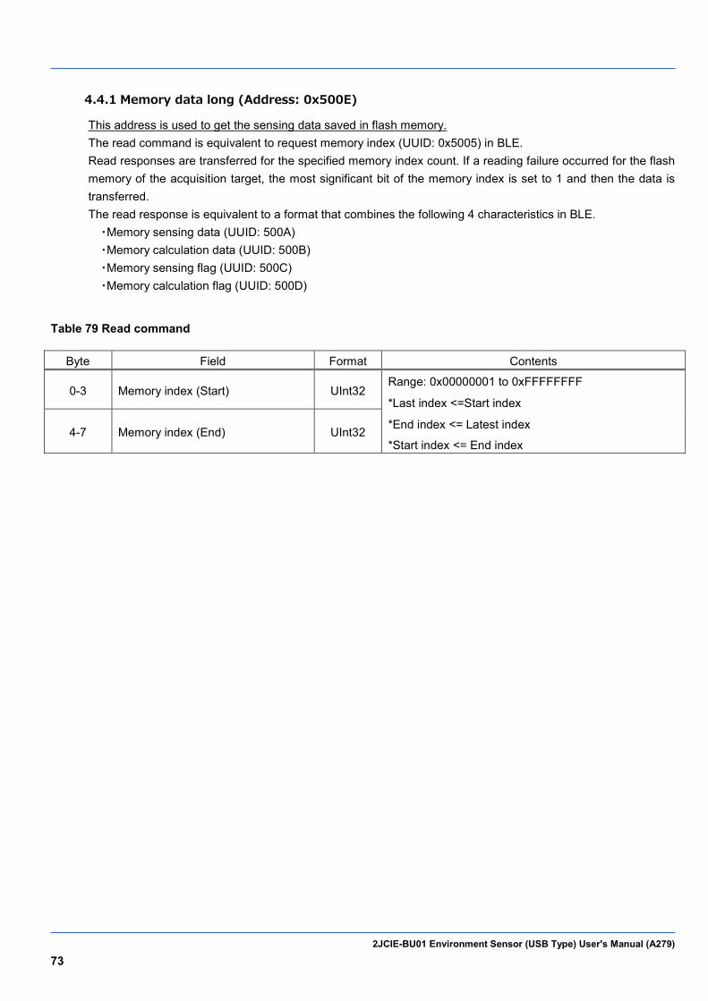
2JCIE-BU01 Environment Sensor (USB Type) User's Manual (A279) 73
4.4.1 Memory data long (Address: 0x500E)
This address is used to get the sensing data saved in flash memory. The read command is equivalent to request memory index (UUID: 0x5005) in BLE. Read responses are transferred for the specified memory index count. If a reading failure occurred for the flash memory of the acquisition target, the most significant bit of the memory index is set to 1 and then the data is transferred. The read response is equivalent to a format that combines the following 4 characteristics in BLE. ・Memory sensing data (UUID: 500A) ・Memory calculation data (UUID: 500B) ・Memory sensing flag (UUID: 500C) ・Memory calculation flag (UUID: 500D)
Table 79 Read command
Byte Field Format Contents
0-3 Memory index (Start) UInt32 Range: 0x00000001 to 0xFFFFFFFF
*Last index <=Start index
*End index <= Latest index
*Start index <= End index 4-7 Memory index (End) UInt32
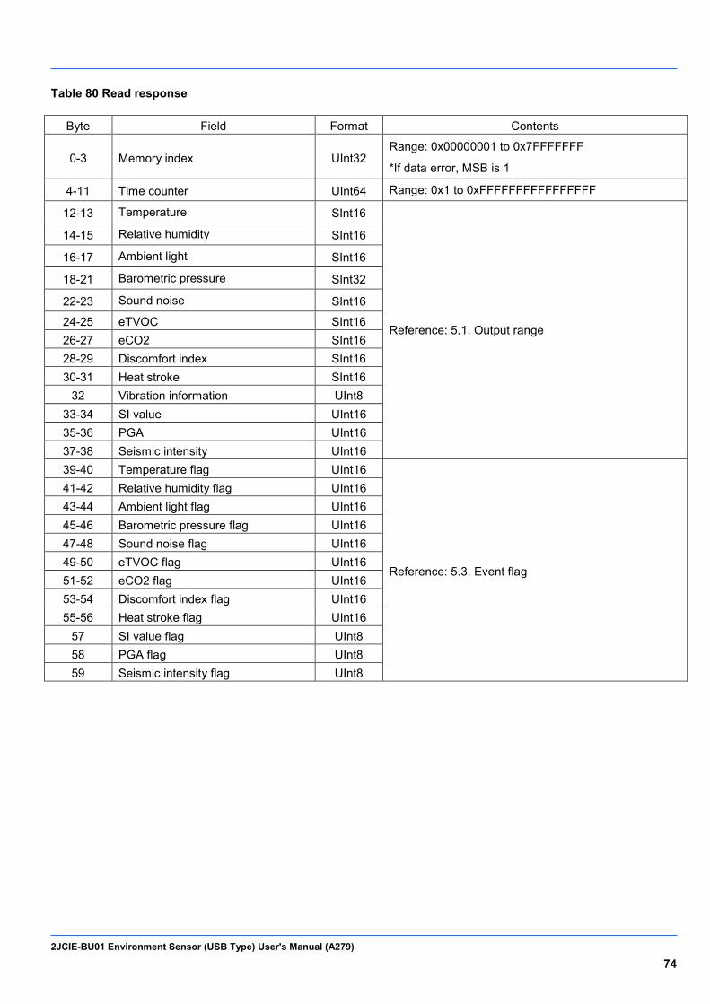
2JCIE-BU01 Environment Sensor (USB Type) User's Manual (A279) 74
Table 80 Read response
Byte Field Format Contents
0-3 Memory index UInt32 Range: 0x00000001 to 0x7FFFFFFF
*If data error, MSB is 1
4-11 Time counter UInt64 Range: 0x1 to 0xFFFFFFFFFFFFFFFF
12-13 Temperature SInt16
Reference: 5.1. Output range
14-15 Relative humidity SInt16
16-17 Ambient light SInt16
18-21 Barometric pressure SInt32
22-23 Sound noise SInt16
24-25 eTVOC SInt16 26-27 eCO2 SInt16 28-29 Discomfort index SInt16 30-31 Heat stroke SInt16
32 Vibration information UInt8 33-34 SI value UInt16 35-36 PGA UInt16 37-38 Seismic intensity UInt16 39-40 Temperature flag UInt16
Reference: 5.3. Event flag
41-42 Relative humidity flag UInt16 43-44 Ambient light flag UInt16 45-46 Barometric pressure flag UInt16 47-48 Sound noise flag UInt16 49-50 eTVOC flag UInt16 51-52 eCO2 flag UInt16 53-54 Discomfort index flag UInt16 55-56 Heat stroke flag UInt16
57 SI value flag UInt8 58 PGA flag UInt8 59 Seismic intensity flag UInt8
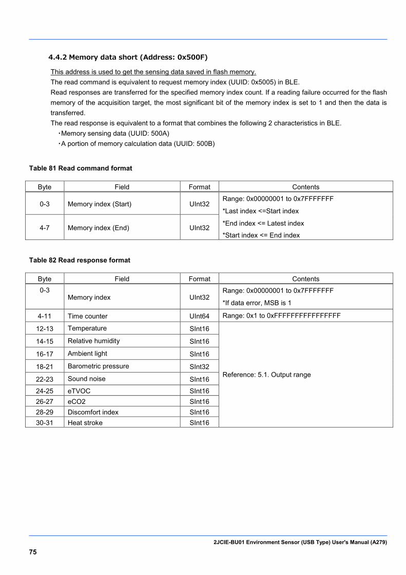
2JCIE-BU01 Environment Sensor (USB Type) User's Manual (A279) 75
4.4.2 Memory data short (Address: 0x500F)
This address is used to get the sensing data saved in flash memory. The read command is equivalent to request memory index (UUID: 0x5005) in BLE. Read responses are transferred for the specified memory index count. If a reading failure occurred for the flash memory of the acquisition target, the most significant bit of the memory index is set to 1 and then the data is transferred. The read response is equivalent to a format that combines the following 2 characteristics in BLE. ・Memory sensing data (UUID: 500A) ・A portion of memory calculation data (UUID: 500B)
Table 81 Read command format
Byte Field Format Contents
0-3 Memory index (Start) UInt32 Range: 0x00000001 to 0x7FFFFFFF
*Last index <=Start index
*End index <= Latest index
*Start index <= End index 4-7 Memory index (End) UInt32
Table 82 Read response format
Byte Field Format Contents 0-3
Memory index UInt32 Range: 0x00000001 to 0x7FFFFFFF
*If data error, MSB is 1
4-11 Time counter UInt64 Range: 0x1 to 0xFFFFFFFFFFFFFFFF
12-13 Temperature SInt16
Reference: 5.1. Output range
14-15 Relative humidity SInt16
16-17 Ambient light SInt16
18-21 Barometric pressure SInt32
22-23 Sound noise SInt16
24-25 eTVOC SInt16 26-27 eCO2 SInt16 28-29 Discomfort index SInt16 30-31 Heat stroke SInt16
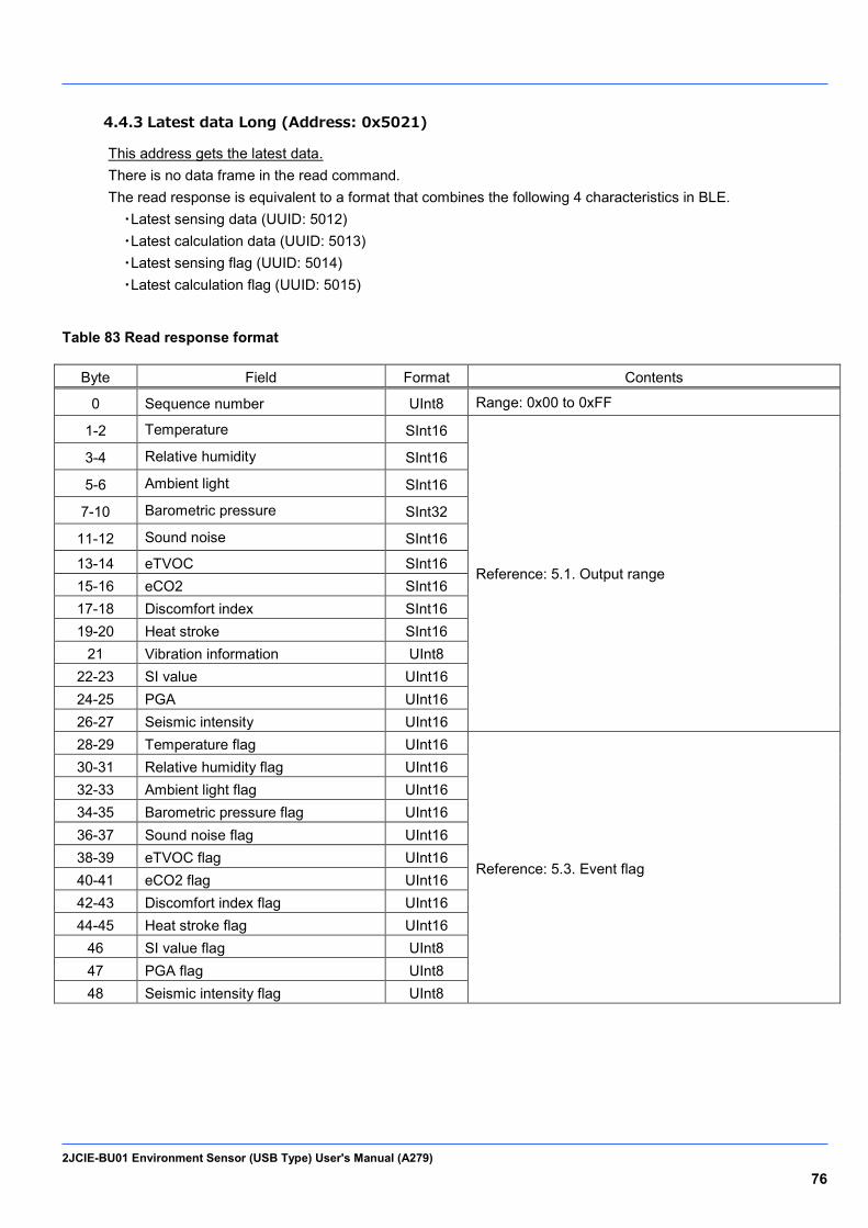
2JCIE-BU01 Environment Sensor (USB Type) User's Manual (A279) 76
4.4.3 Latest data Long (Address: 0x5021)
This address gets the latest data. There is no data frame in the read command. The read response is equivalent to a format that combines the following 4 characteristics in BLE. ・Latest sensing data (UUID: 5012) ・Latest calculation data (UUID: 5013) ・Latest sensing flag (UUID: 5014) ・Latest calculation flag (UUID: 5015)
Table 83 Read response format
Byte Field Format Contents
0 Sequence number UInt8 Range: 0x00 to 0xFF
1-2 Temperature SInt16
Reference: 5.1. Output range
3-4 Relative humidity SInt16
5-6 Ambient light SInt16
7-10 Barometric pressure SInt32
11-12 Sound noise SInt16
13-14 eTVOC SInt16 15-16 eCO2 SInt16 17-18 Discomfort index SInt16 19-20 Heat stroke SInt16
21 Vibration information UInt8 22-23 SI value UInt16 24-25 PGA UInt16 26-27 Seismic intensity UInt16 28-29 Temperature flag UInt16
Reference: 5.3. Event flag
30-31 Relative humidity flag UInt16 32-33 Ambient light flag UInt16 34-35 Barometric pressure flag UInt16 36-37 Sound noise flag UInt16 38-39 eTVOC flag UInt16 40-41 eCO2 flag UInt16 42-43 Discomfort index flag UInt16 44-45 Heat stroke flag UInt16
46 SI value flag UInt8 47 PGA flag UInt8 48 Seismic intensity flag UInt8

2JCIE-BU01 Environment Sensor (USB Type) User's Manual (A279) 77
4.4.4 Latest data short (Address: 0x5022)
This address gets the latest data. There is no data frame in the read command. The read response is equivalent to a format that combines the following 2 characteristics in BLE. ・Latest sensing data (UUID: 5012) ・A portion of latest calculation data (UUID: 5013)
Table 84 Read response format
Byte Field Format Contents
0 Sequence number UInt8 Range: 0x00 to 0xFF
1-2 Temperature SInt16
Reference: 5.1. Output range
3-4 Relative humidity SInt16
5-6 Ambient light SInt16
7-10 Barometric pressure SInt32
11-12 Sound noise SInt16
13-14 eTVOC SInt16 15-16 eCO2 SInt16 17-18 Discomfort index SInt16 19-20 Heat stroke SInt16

2JCIE-BU01 Environment Sensor (USB Type) User's Manual (A279) 78
4.4.5 Acceleration memory data [Header] (Address: 0x503E)
This address is used to get the acceleration data saved in flash memory. The read command is equivalent to request acceleration memory index (UUID: 0x5032) in BLE. The read response is equivalent to a format that combines the split packets of acceleration memory data [Header] (0x5034) in BLE.
Table 85 Read command format
Byte Field Format Contents
0 Acceleration data type UInt8 0x00: Earthquake data (Normal mode)
0x01: Vibration data (Normal mode)
1 Request acceleration memory index
UInt8 Range: 0x01 to 0x0A (1 to 10)
*0x01: Latest data <---> 0x0A: Last data
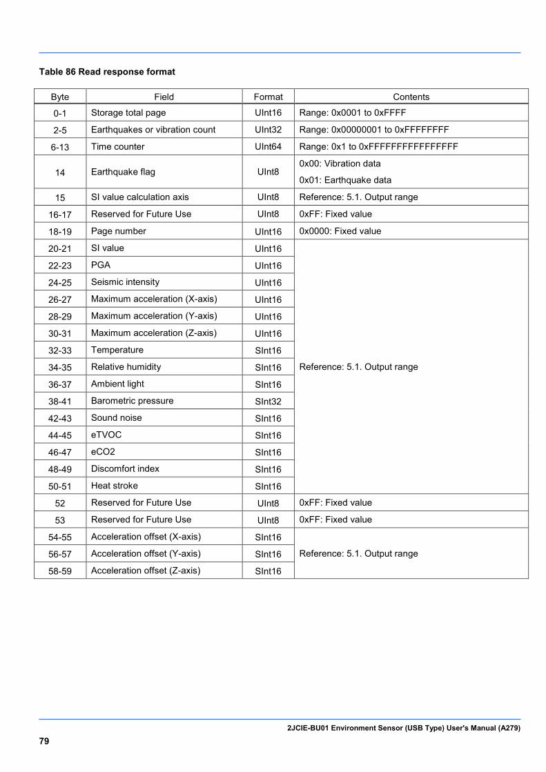
2JCIE-BU01 Environment Sensor (USB Type) User's Manual (A279) 79
Table 86 Read response format
Byte Field Format Contents
0-1 Storage total page UInt16 Range: 0x0001 to 0xFFFF
2-5 Earthquakes or vibration count UInt32 Range: 0x00000001 to 0xFFFFFFFF
6-13 Time counter UInt64 Range: 0x1 to 0xFFFFFFFFFFFFFFFF
14 Earthquake flag UInt8 0x00: Vibration data
0x01: Earthquake data
15 SI value calculation axis UInt8 Reference: 5.1. Output range
16-17 Reserved for Future Use UInt8 0xFF: Fixed value
18-19 Page number UInt16 0x0000: Fixed value
20-21 SI value UInt16
Reference: 5.1. Output range
22-23 PGA UInt16
24-25 Seismic intensity UInt16
26-27 Maximum acceleration (X-axis) UInt16
28-29 Maximum acceleration (Y-axis) UInt16
30-31 Maximum acceleration (Z-axis) UInt16
32-33 Temperature SInt16
34-35 Relative humidity SInt16
36-37 Ambient light SInt16
38-41 Barometric pressure SInt32
42-43 Sound noise SInt16
44-45 eTVOC SInt16
46-47 eCO2 SInt16
48-49 Discomfort index SInt16
50-51 Heat stroke SInt16
52 Reserved for Future Use UInt8 0xFF: Fixed value
53 Reserved for Future Use UInt8 0xFF: Fixed value
54-55 Acceleration offset (X-axis) SInt16
Reference: 5.1. Output range 56-57 Acceleration offset (Y-axis) SInt16
58-59 Acceleration offset (Z-axis) SInt16
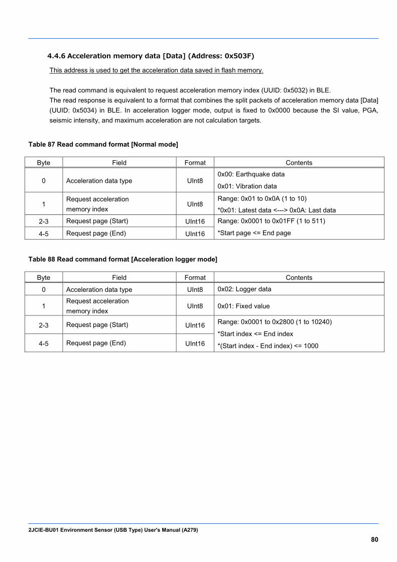
2JCIE-BU01 Environment Sensor (USB Type) User's Manual (A279) 80
4.4.6 Acceleration memory data [Data] (Address: 0x503F)
This address is used to get the acceleration data saved in flash memory. The read command is equivalent to request acceleration memory index (UUID: 0x5032) in BLE. The read response is equivalent to a format that combines the split packets of acceleration memory data [Data] (UUID: 0x5034) in BLE. In acceleration logger mode, output is fixed to 0x0000 because the SI value, PGA, seismic intensity, and maximum acceleration are not calculation targets.
Table 87 Read command format [Normal mode]
Byte Field Format Contents
0 Acceleration data type UInt8 0x00: Earthquake data
0x01: Vibration data
1 Request acceleration memory index
UInt8 Range: 0x01 to 0x0A (1 to 10)
*0x01: Latest data <---> 0x0A: Last data
2-3 Request page (Start) UInt16 Range: 0x0001 to 0x01FF (1 to 511)
*Start page <= End page 4-5 Request page (End) UInt16
Table 88 Read command format [Acceleration logger mode]
Byte Field Format Contents
0 Acceleration data type UInt8 0x02: Logger data
1 Request acceleration memory index
UInt8 0x01: Fixed value
2-3 Request page (Start) UInt16 Range: 0x0001 to 0x2800 (1 to 10240)
*Start index <= End index
*(Start index - End index) <= 1000 4-5 Request page (End) UInt16
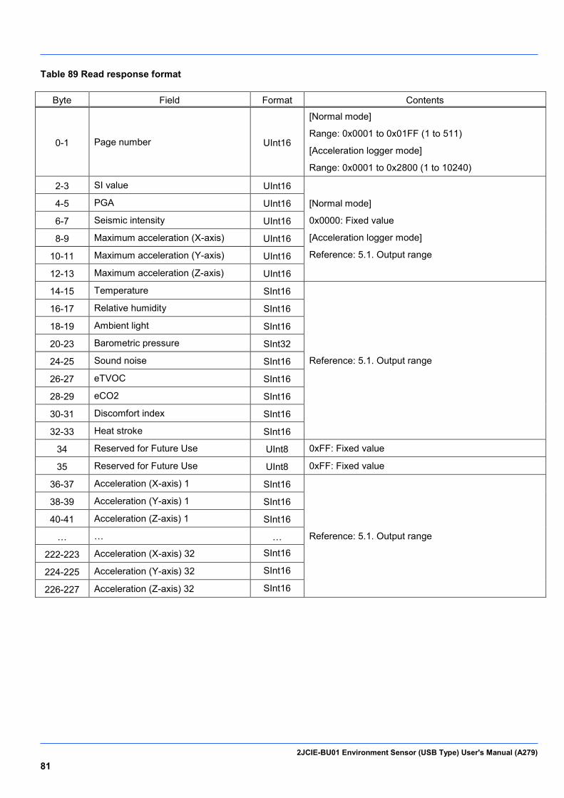
2JCIE-BU01 Environment Sensor (USB Type) User's Manual (A279) 81
Table 89 Read response format
Byte Field Format Contents
0-1 Page number UInt16
[Normal mode]
Range: 0x0001 to 0x01FF (1 to 511)
[Acceleration logger mode]
Range: 0x0001 to 0x2800 (1 to 10240)
2-3 SI value UInt16
[Normal mode]
0x0000: Fixed value
[Acceleration logger mode]
Reference: 5.1. Output range
4-5 PGA UInt16
6-7 Seismic intensity UInt16
8-9 Maximum acceleration (X-axis) UInt16
10-11 Maximum acceleration (Y-axis) UInt16
12-13 Maximum acceleration (Z-axis) UInt16
14-15 Temperature SInt16
Reference: 5.1. Output range
16-17 Relative humidity SInt16
18-19 Ambient light SInt16
20-23 Barometric pressure SInt32
24-25 Sound noise SInt16
26-27 eTVOC SInt16
28-29 eCO2 SInt16
30-31 Discomfort index SInt16
32-33 Heat stroke SInt16
34 Reserved for Future Use UInt8 0xFF: Fixed value
35 Reserved for Future Use UInt8 0xFF: Fixed value
36-37 Acceleration (X-axis) 1 SInt16
Reference: 5.1. Output range
38-39 Acceleration (Y-axis) 1 SInt16
40-41 Acceleration (Z-axis) 1 SInt16
… … …
222-223 Acceleration (X-axis) 32 SInt16
224-225 Acceleration (Y-axis) 32 SInt16
226-227 Acceleration (Z-axis) 32 SInt16

2JCIE-BU01 Environment Sensor (USB Type) User's Manual (A279) 82
BLE common address 4.5.
These addresses are linked to BLE services and characteristics. The BLE UUID and USB address have a one-to-one correspondence.
Table 90 List of Address in Memory Data Service
Address Description Read Write with
FLASH storage
Write without
FLASH storage
0x5004 Latest memory information √
Table 91 List of Address in Latest Data Service
Address Description Read Write with
FLASH storage
Write without
FLASH storage
0x5012 Latest sensing data √
0x5013 Latest calculation data √
0x5014 Latest sensing flag √
0x5015 Latest calculation flag √
0x5016 Latest acceleration status √
Table 92 List of Address in Acceleration Service
Address Description Read Write with
FLASH storage
Write without
FLASH storage
0x5031 Vibration count √
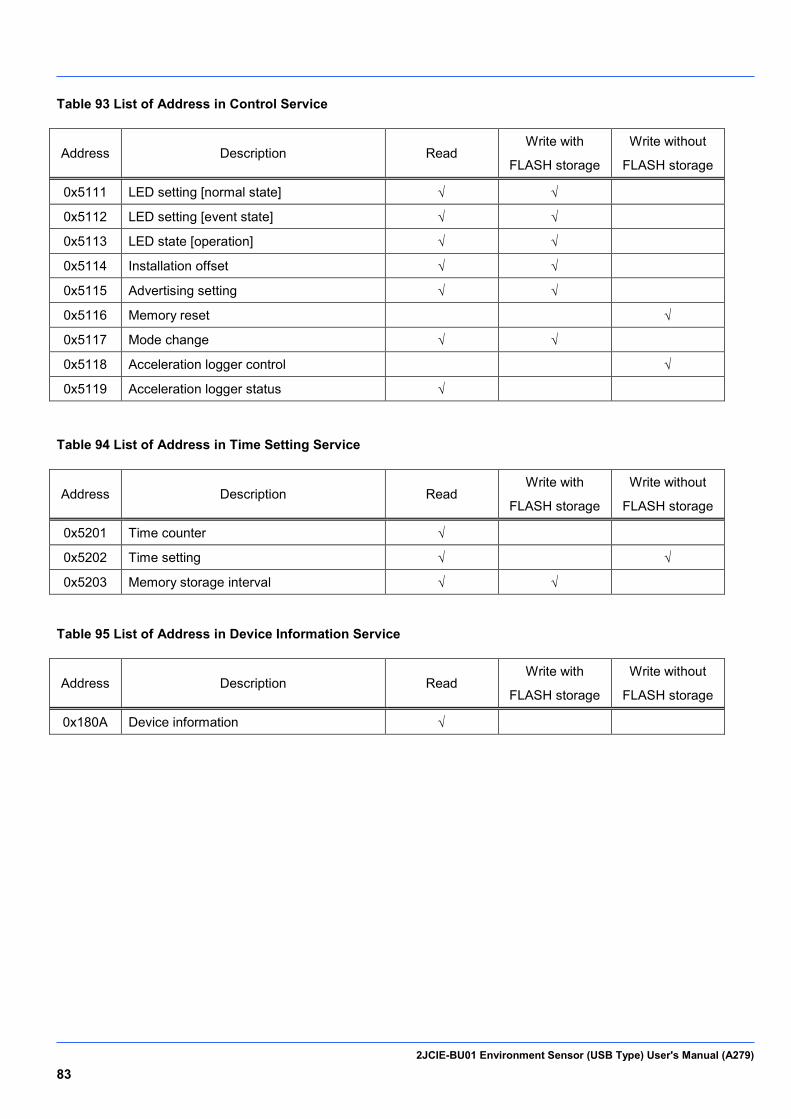
2JCIE-BU01 Environment Sensor (USB Type) User's Manual (A279) 83
Table 93 List of Address in Control Service
Address Description Read Write with
FLASH storage
Write without
FLASH storage
0x5111 LED setting [normal state] √ √
0x5112 LED setting [event state] √ √
0x5113 LED state [operation] √ √
0x5114 Installation offset √ √
0x5115 Advertising setting √ √
0x5116 Memory reset √
0x5117 Mode change √ √
0x5118 Acceleration logger control √
0x5119 Acceleration logger status √
Table 94 List of Address in Time Setting Service
Address Description Read Write with
FLASH storage
Write without
FLASH storage
0x5201 Time counter √
0x5202 Time setting √ √
0x5203 Memory storage interval √ √
Table 95 List of Address in Device Information Service
Address Description Read Write with
FLASH storage
Write without
FLASH storage
0x180A Device information √
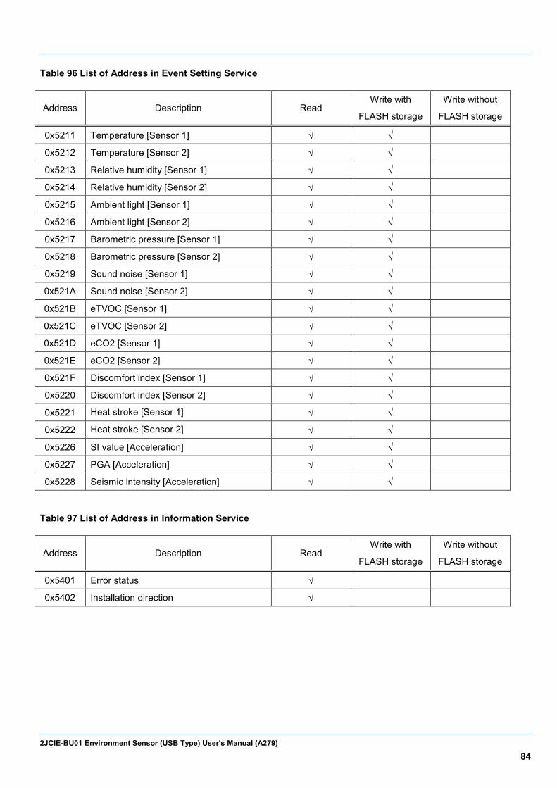
2JCIE-BU01 Environment Sensor (USB Type) User's Manual (A279) 84
Table 96 List of Address in Event Setting Service
Address Description Read Write with
FLASH storage
Write without
FLASH storage
0x5211 Temperature [Sensor 1] √ √
0x5212 Temperature [Sensor 2] √ √
0x5213 Relative humidity [Sensor 1] √ √
0x5214 Relative humidity [Sensor 2] √ √
0x5215 Ambient light [Sensor 1] √ √
0x5216 Ambient light [Sensor 2] √ √
0x5217 Barometric pressure [Sensor 1] √ √
0x5218 Barometric pressure [Sensor 2] √ √
0x5219 Sound noise [Sensor 1] √ √
0x521A Sound noise [Sensor 2] √ √
0x521B eTVOC [Sensor 1] √ √
0x521C eTVOC [Sensor 2] √ √
0x521D eCO2 [Sensor 1] √ √
0x521E eCO2 [Sensor 2] √ √
0x521F Discomfort index [Sensor 1] √ √
0x5220 Discomfort index [Sensor 2] √ √
0x5221 Heat stroke [Sensor 1] √ √
0x5222 Heat stroke [Sensor 2] √ √
0x5226 SI value [Acceleration] √ √
0x5227 PGA [Acceleration] √ √
0x5228 Seismic intensity [Acceleration] √ √
Table 97 List of Address in Information Service
Address Description Read Write with
FLASH storage
Write without
FLASH storage
0x5401 Error status √
0x5402 Installation direction √

2JCIE-BU01 Environment Sensor (USB Type) User's Manual (A279) 85
4.5.1 Latest memory information (Address: 0x5004)
This address is used to get the number of indexes of sensing data saved in flash memory. The maximum amount of saved data is 60,000 items of data between memory index (latest) and memory index (last). If the memory indexes exceed 60,000 items, the data will be overwritten in order from the oldest data. Only the data between memory index (latest) and memory index (last) can be acquired. There is no data frame in the read command.
Table 98 Read response format
Byte Field Format Contents 0-3 Memory index (Latest) UInt32 Range: 0x00000001 to 0x7FFFFFFF
*0x00000000: Before storage 4-7 Memory index (Last) UInt32
4.5.2 Latest sensing data (Address: 0x5012)
This characteristic is used to get the latest sensing data. The latest values at the time of reading are returned. There is no data frame in the read command.
Table 99 Read response format
Byte Field Format Contents
0 Sequence number UInt8 Range: 0x00 to 0xFF
1-2 Temperature SInt16
Reference: 5.1. Output range
3-4 Relative humidity SInt16
5-6 Ambient light SInt16
7-10 Barometric pressure SInt32
11-12 Sound noise SInt16
13-14 eTVOC SInt16 15-16 eCO2 SInt16
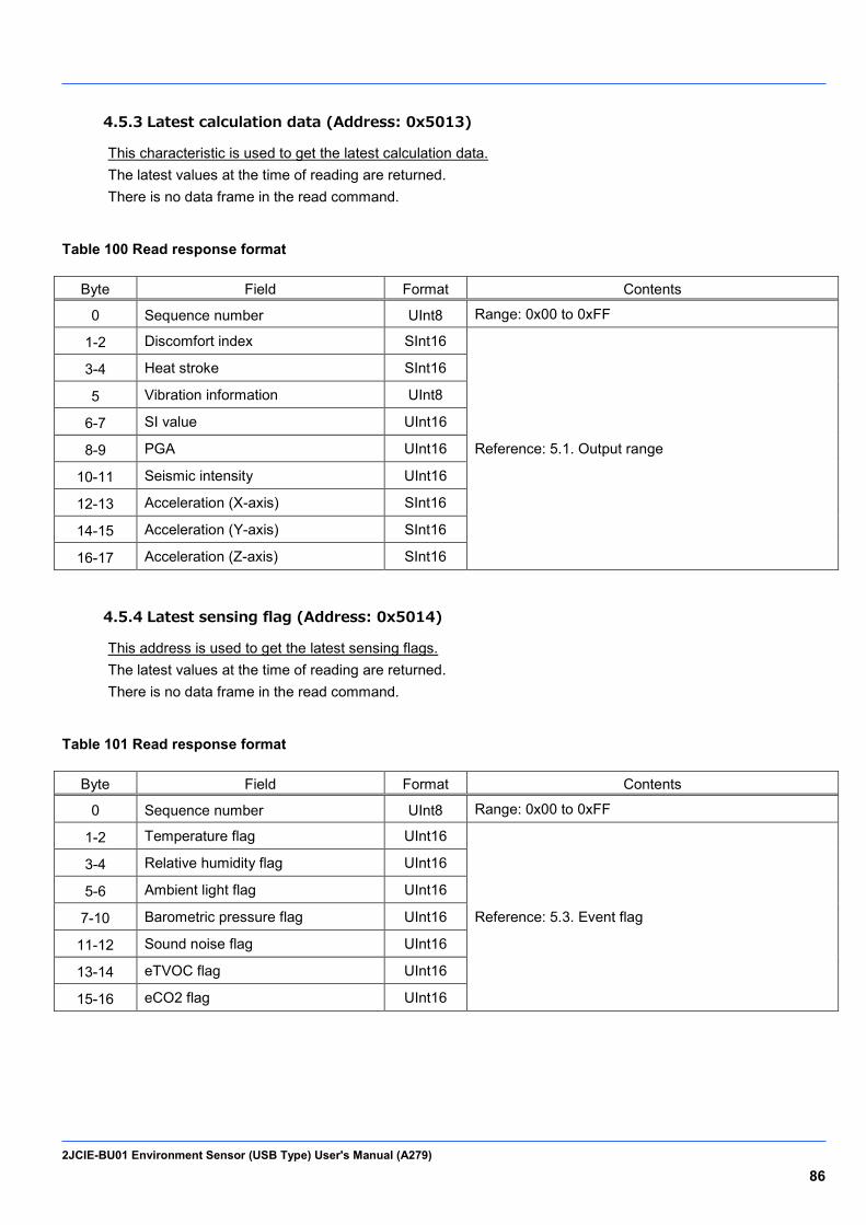
2JCIE-BU01 Environment Sensor (USB Type) User's Manual (A279) 86
4.5.3 Latest calculation data (Address: 0x5013)
This characteristic is used to get the latest calculation data. The latest values at the time of reading are returned. There is no data frame in the read command.
Table 100 Read response format
Byte Field Format Contents
0 Sequence number UInt8 Range: 0x00 to 0xFF
1-2 Discomfort index SInt16
Reference: 5.1. Output range
3-4 Heat stroke SInt16
5 Vibration information UInt8
6-7 SI value UInt16
8-9 PGA UInt16
10-11 Seismic intensity UInt16
12-13 Acceleration (X-axis) SInt16
14-15 Acceleration (Y-axis) SInt16
16-17 Acceleration (Z-axis) SInt16
4.5.4 Latest sensing flag (Address: 0x5014)
This address is used to get the latest sensing flags. The latest values at the time of reading are returned. There is no data frame in the read command.
Table 101 Read response format
Byte Field Format Contents
0 Sequence number UInt8 Range: 0x00 to 0xFF
1-2 Temperature flag UInt16
Reference: 5.3. Event flag
3-4 Relative humidity flag UInt16
5-6 Ambient light flag UInt16
7-10 Barometric pressure flag UInt16
11-12 Sound noise flag UInt16
13-14 eTVOC flag UInt16
15-16 eCO2 flag UInt16
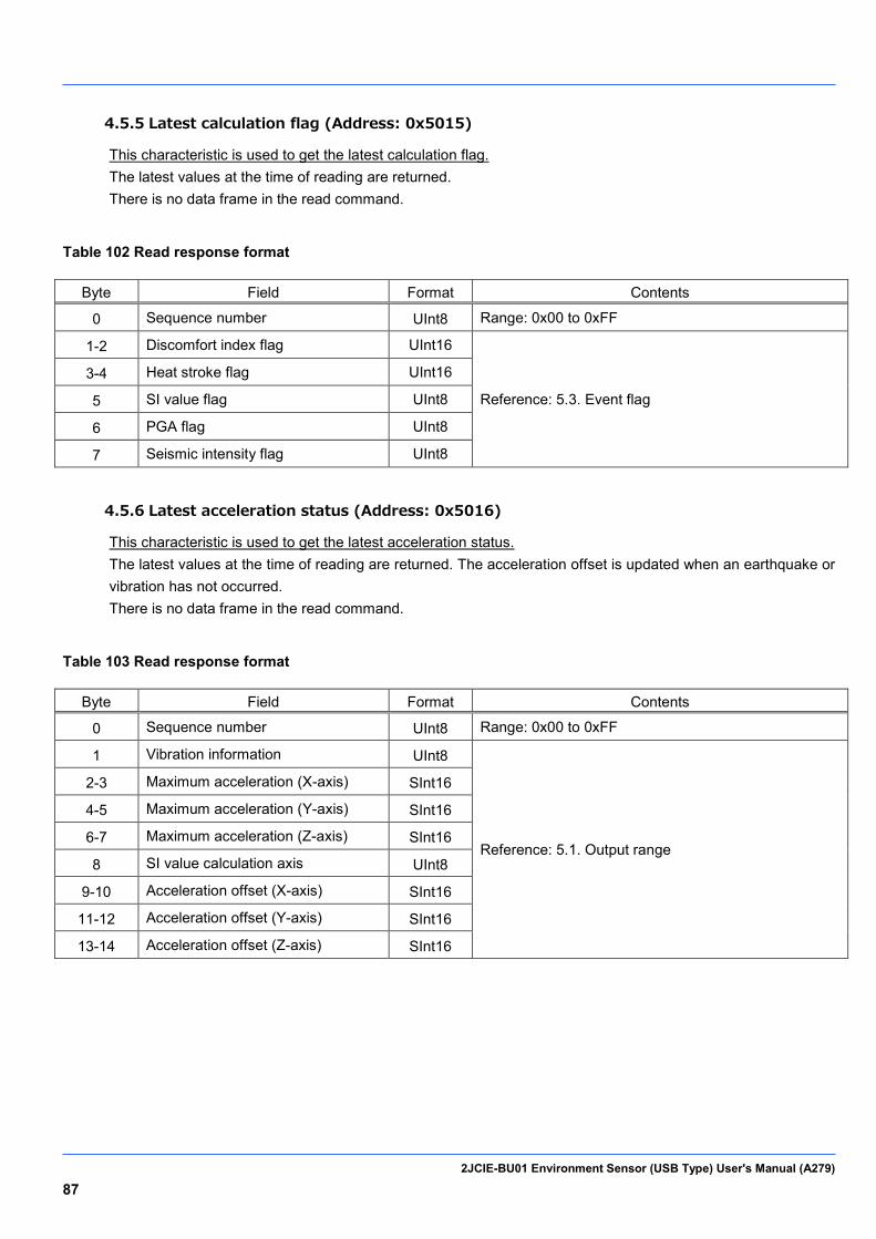
2JCIE-BU01 Environment Sensor (USB Type) User's Manual (A279) 87
4.5.5 Latest calculation flag (Address: 0x5015)
This characteristic is used to get the latest calculation flag. The latest values at the time of reading are returned. There is no data frame in the read command.
Table 102 Read response format
Byte Field Format Contents
0 Sequence number UInt8 Range: 0x00 to 0xFF
1-2 Discomfort index flag UInt16
Reference: 5.3. Event flag
3-4 Heat stroke flag UInt16
5 SI value flag UInt8
6 PGA flag UInt8
7 Seismic intensity flag UInt8
4.5.6 Latest acceleration status (Address: 0x5016)
This characteristic is used to get the latest acceleration status. The latest values at the time of reading are returned. The acceleration offset is updated when an earthquake or vibration has not occurred. There is no data frame in the read command.
Table 103 Read response format
Byte Field Format Contents
0 Sequence number UInt8 Range: 0x00 to 0xFF
1 Vibration information UInt8
Reference: 5.1. Output range
2-3 Maximum acceleration (X-axis) SInt16
4-5 Maximum acceleration (Y-axis) SInt16
6-7 Maximum acceleration (Z-axis) SInt16
8 SI value calculation axis UInt8
9-10 Acceleration offset (X-axis) SInt16
11-12 Acceleration offset (Y-axis) SInt16
13-14 Acceleration offset (Z-axis) SInt16
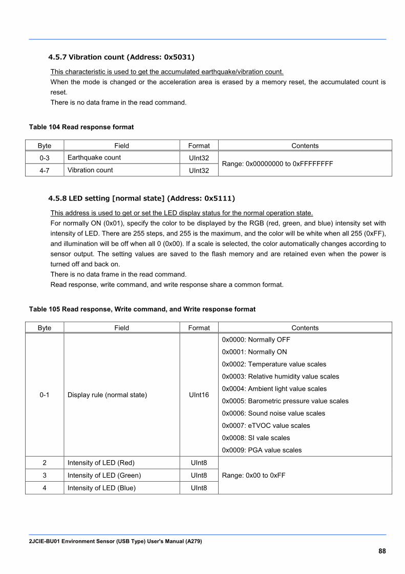
2JCIE-BU01 Environment Sensor (USB Type) User's Manual (A279) 88
4.5.7 Vibration count (Address: 0x5031)
This characteristic is used to get the accumulated earthquake/vibration count. When the mode is changed or the acceleration area is erased by a memory reset, the accumulated count is reset. There is no data frame in the read command.
Table 104 Read response format
Byte Field Format Contents
0-3 Earthquake count UInt32 Range: 0x00000000 to 0xFFFFFFFF
4-7 Vibration count UInt32
4.5.8 LED setting [normal state] (Address: 0x5111)
This address is used to get or set the LED display status for the normal operation state. For normally ON (0x01), specify the color to be displayed by the RGB (red, green, and blue) intensity set with intensity of LED. There are 255 steps, and 255 is the maximum, and the color will be white when all 255 (0xFF), and illumination will be off when all 0 (0x00). If a scale is selected, the color automatically changes according to sensor output. The setting values are saved to the flash memory and are retained even when the power is turned off and back on. There is no data frame in the read command. Read response, write command, and write response share a common format.
Table 105 Read response, Write command, and Write response format
Byte Field Format Contents
0-1 Display rule (normal state) UInt16
0x0000: Normally OFF
0x0001: Normally ON
0x0002: Temperature value scales
0x0003: Relative humidity value scales
0x0004: Ambient light value scales
0x0005: Barometric pressure value scales
0x0006: Sound noise value scales
0x0007: eTVOC value scales
0x0008: SI vale scales
0x0009: PGA value scales
2 Intensity of LED (Red) UInt8
Range: 0x00 to 0xFF 3 Intensity of LED (Green) UInt8
4 Intensity of LED (Blue) UInt8

2JCIE-BU01 Environment Sensor (USB Type) User's Manual (A279) 89
4.5.9 LED setting [event state] (Address: 0x5112)
This address is used to get or set the LED display status when an event occurs. For when an event occurs, specify the color to flash by the RGB (red, green, blue) intensity set with intensity of LED. There are 255 steps, and 255 is the maximum, and the color will be white when all 255 (0xFF), and illumination will be off when all 0 (0x00). Events are bit field settings so multiple events can be set at the same time. The setting values are saved to the flash memory and are retained even when the power is turned off and back on. There is no data frame in the read command. Read response, write command, and write response share a common format.
Table 106 Read response, Write command, and Write response format
Byte Field Format Contents
0-1 Display rule (event state) UInt16
Bit7: PGA event
Bit6: SI value event
Bit5: eTVOC event
Bit4: Sound noise event
Bit3: Barometric pressure event
Bit2: Ambient light event
Bit1: Relative humidity event
Bit0: Temperature event
2 Intensity of LED (Red) UInt8
Range: 0x00 to 0xFF 3 Intensity of LED (Green) UInt8
4 Intensity of LED (Blue) UInt8
4.5.10 LED setting [operation] (Address: 0x5113)
This address is used to get or set the LED display status of each operation. Start up applies only after startup, Error applies when any error status occurs, and Connection applies when connected via BLE communication. The setting values are written to flash memory and are retained even when the power is turned off and back on. There is no data frame in the read command. Read response, write command, and write response share a common format.
Table 107 Read response, Write command, and Write response format
Byte Field Format Contents
0 Start up UInt8 0x00: Rainbow (default)
0x01: BLUE
1 Error UInt8 0x00: NONE (default)
0x01: RED
2 Connection UInt8 0x00: NONE (default)
0x01: GREEN ON 1 sec
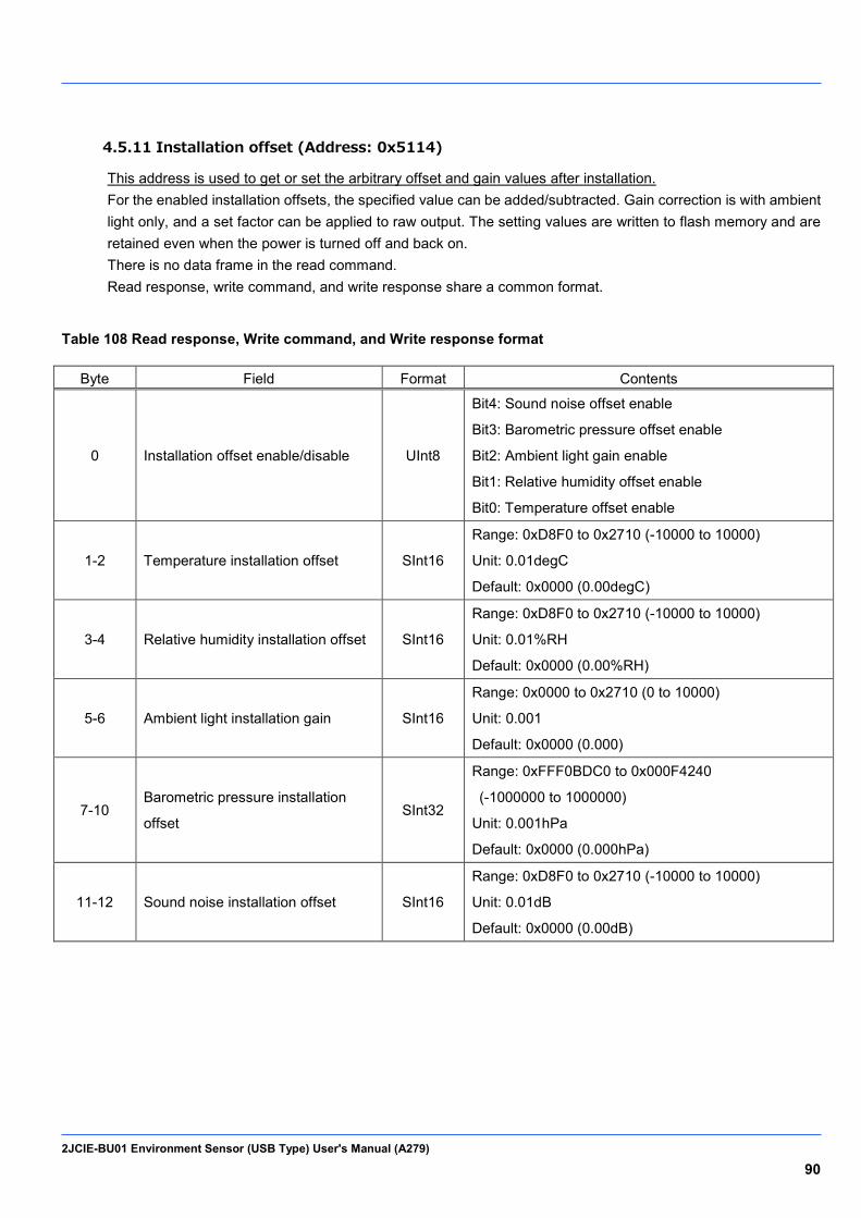
2JCIE-BU01 Environment Sensor (USB Type) User's Manual (A279) 90
4.5.11 Installation offset (Address: 0x5114)
This address is used to get or set the arbitrary offset and gain values after installation. For the enabled installation offsets, the specified value can be added/subtracted. Gain correction is with ambient light only, and a set factor can be applied to raw output. The setting values are written to flash memory and are retained even when the power is turned off and back on. There is no data frame in the read command. Read response, write command, and write response share a common format.
Table 108 Read response, Write command, and Write response format
Byte Field Format Contents
0 Installation offset enable/disable UInt8
Bit4: Sound noise offset enable
Bit3: Barometric pressure offset enable
Bit2: Ambient light gain enable
Bit1: Relative humidity offset enable
Bit0: Temperature offset enable
1-2 Temperature installation offset SInt16
Range: 0xD8F0 to 0x2710 (-10000 to 10000)
Unit: 0.01degC
Default: 0x0000 (0.00degC)
3-4 Relative humidity installation offset SInt16
Range: 0xD8F0 to 0x2710 (-10000 to 10000)
Unit: 0.01%RH
Default: 0x0000 (0.00%RH)
5-6 Ambient light installation gain SInt16
Range: 0x0000 to 0x2710 (0 to 10000)
Unit: 0.001
Default: 0x0000 (0.000)
7-10 Barometric pressure installation
offset SInt32
Range: 0xFFF0BDC0 to 0x000F4240
(-1000000 to 1000000)
Unit: 0.001hPa
Default: 0x0000 (0.000hPa)
11-12 Sound noise installation offset SInt16
Range: 0xD8F0 to 0x2710 (-10000 to 10000)
Unit: 0.01dB
Default: 0x0000 (0.00dB)

2JCIE-BU01 Environment Sensor (USB Type) User's Manual (A279) 91
4.5.12 Advertise setting (Address: 0x5115)
This address is used to get or set the BLE advertising transmission interval and data type. For the configuration of advertising packets, refer to "3. BLE Advertising packet." If Reserved for Future Use (0x06 to 0x08) is selected for the advertising mode, the advertising packet of the sensor data (0x01) is selected. The setting values are saved to the flash memory and are retained even when the power is turned off and back on. There is no data frame in the read command. Read response, write command, and write response share a common format.
Table 109 Read response, Write command, and Write response format
Byte Field Format Contents
0-1 Advertising interval UInt16
Range: 0x00A0 to 0x4000 (100ms to 10.24s)
Unit: 0.625 ms
Default: 0x00A0 (100ms)
2 Advertising mode UInt8
0x01: Sensor data (default)
0x02: Acceleration data
0x03: Sensor data & Acceleration data (Scan rsp)
0x04: Sensor flag & Acceleration flag (Scan rsp)
0x05: Serial number
0x06: Reserve for Future Use
0x07: Reserve for Future Use
0x08: Reserve for Future Use
4.5.13 Memory reset (Address: 0x5116)
This address is used to erase the flash memory data of the relevant area. The sensing data area is a ring buffer so the old data is erased automatically, but if you wish to reset the memory index, clear the sensing data area by a memory reset. For the acceleration area, this is used to erase the data in the acceleration logger mode. The erase time is approximately 2 minutes and the LED lights blue. Even if USB communication is received during erasing, a response is not made. Write command and write response share a common format.
Table 110 Write command and Write response format
Byte Field Format Contents
0 Memory reset UInt8 0x01: Sensing data area
0x02: Acceleration area

2JCIE-BU01 Environment Sensor (USB Type) User's Manual (A279) 92
4.5.14 Mode change (Address: 0x5117)
This address is used to get the current mode or set the mode. Since the flash memory in acceleration area is erased when the mode is switched, the state becomes the same as when the acceleration area is erased with a memory reset, and it takes approximately 2 minutes. The setting value is saved to flash memory, and startup is in the same mode even when the power is turned off and back on. There is no data frame in the read command. Read response, write command, and write response share a common format.
Table 111 Read response, Write command, and Write response format
Byte Field Format Contents
0 Mode change UInt8 0x00: Normal mode (default)
0x01: Acceleration logger mode
4.5.15 Acceleration logger control (Address: 0x5118)
This address is used to start and stop the log of the acceleration logger mode. When stopping the log, set the values for byte 1 to byte 6 to the same values as when starting the log. The start page and end page can be set arbitrarily by the user, but a memory reset needs to be performed when data will be written to the same page because data cannot be obtained normally if a page with data written is overwritten. Write command and write response share a common format.
Table 112 Write command and Write response format
Byte Field Format Contents
0 Logger condition UInt8 0x00: Log stop
0x01: Log start
1 Range of detection UInt8 0x00: ±2000 gal (fixed value)
2 ODR setting UInt8
0x00: 1 Hz
0x01: 10 Hz
0x02: 25 Hz
0x03: 100 Hz
0x04: 200 Hz
0x05: 400 Hz
3-4 Start page UInt16 Range: 0x0001 to 0x2800 (1 to 10240)
Unit: 1 page 5-6 End page UInt16
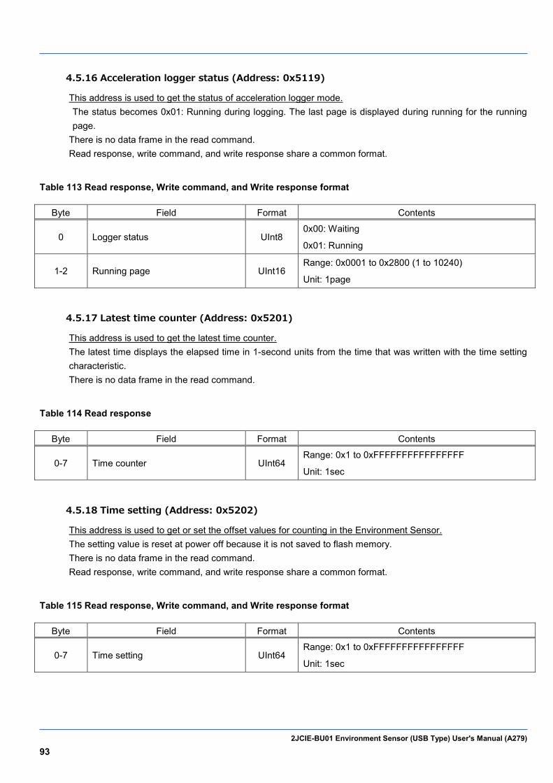
2JCIE-BU01 Environment Sensor (USB Type) User's Manual (A279) 93
4.5.16 Acceleration logger status (Address: 0x5119)
This address is used to get the status of acceleration logger mode. The status becomes 0x01: Running during logging. The last page is displayed during running for the running page.
There is no data frame in the read command. Read response, write command, and write response share a common format.
Table 113 Read response, Write command, and Write response format
Byte Field Format Contents
0 Logger status UInt8 0x00: Waiting
0x01: Running
1-2 Running page UInt16 Range: 0x0001 to 0x2800 (1 to 10240)
Unit: 1page
4.5.17 Latest time counter (Address: 0x5201)
This address is used to get the latest time counter. The latest time displays the elapsed time in 1-second units from the time that was written with the time setting characteristic. There is no data frame in the read command.
Table 114 Read response
Byte Field Format Contents
0-7 Time counter UInt64 Range: 0x1 to 0xFFFFFFFFFFFFFFFF
Unit: 1sec
4.5.18 Time setting (Address: 0x5202)
This address is used to get or set the offset values for counting in the Environment Sensor. The setting value is reset at power off because it is not saved to flash memory. There is no data frame in the read command. Read response, write command, and write response share a common format.
Table 115 Read response, Write command, and Write response format
Byte Field Format Contents
0-7 Time setting UInt64 Range: 0x1 to 0xFFFFFFFFFFFFFFFF
Unit: 1sec
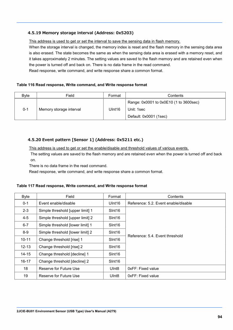
2JCIE-BU01 Environment Sensor (USB Type) User's Manual (A279) 94
4.5.19 Memory storage interval (Address: 0x5203)
This address is used to get or set the interval to save the sensing data in flash memory. When the storage interval is changed, the memory index is reset and the flash memory in the sensing data area is also erased. The state becomes the same as when the sensing data area is erased with a memory reset, and it takes approximately 2 minutes. The setting values are saved to the flash memory and are retained even when the power is turned off and back on. There is no data frame in the read command. Read response, write command, and write response share a common format.
Table 116 Read response, Write command, and Write response format
Byte Field Format Contents
0-1 Memory storage interval UInt16
Range: 0x0001 to 0x0E10 (1 to 3600sec)
Unit: 1sec
Default: 0x0001 (1sec)
4.5.20 Event pattern [Sensor 1] (Address: 0x5211 etc.)
This address is used to get or set the enable/disable and threshold values of various events. The setting values are saved to the flash memory and are retained even when the power is turned off and back on.
There is no data frame in the read command. Read response, write command, and write response share a common format.
Table 117 Read response, Write command, and Write response format
Byte Field Format Contents
0-1 Event enable/disable UInt16 Reference: 5.2. Event enable/disable
2-3 Simple threshold [upper limit] 1 SInt16
Reference: 5.4. Event threshold
4-5 Simple threshold [upper limit] 2 SInt16
6-7 Simple threshold [lower limit] 1 SInt16
8-9 Simple threshold [lower limit] 2 SInt16
10-11 Change threshold [rise] 1 SInt16
12-13 Change threshold [rise] 2 SInt16
14-15 Change threshold [decline] 1 SInt16
16-17 Change threshold [decline] 2 SInt16
18 Reserve for Future Use UInt8 0xFF: Fixed value
19 Reserve for Future Use UInt8 0xFF: Fixed value

2JCIE-BU01 Environment Sensor (USB Type) User's Manual (A279) 95
4.5.21 Event pattern [Sensor 2] (Address: 0x5212 etc.)
This address is used to get or set the threshold values of various events. The setting values are saved to the flash memory and are retained even when the power is turned off and back on. There is no data frame in the read command. Read response, write command, and write response share a common format.
Table 118 Read response, Write command, and Write response format
Byte Field Format Contents
0-1 Average value threshold [upper] SInt16
Reference: 5.4 Event threshold
2-3 Average value threshold [lower] SInt16
4-5 Peak to Peak threshold [upper] SInt16
6-7 Peak to Peak threshold [lower] SInt16
8-9 Interval difference threshold [upper] SInt16
10-11 Interval difference threshold [lower] SInt16
12-13 Base difference threshold [upper] SInt16
14-15 Base difference threshold [lower] SInt16
16 Average value count UInt8
17 Peak to Peak count UInt8
18 Interval difference count UInt8
19 Base difference count UInt8

2JCIE-BU01 Environment Sensor (USB Type) User's Manual (A279) 96
4.5.22 Event pattern [Acceleration] (Address: 0x5226 etc.)
This address is used to get or set the enable/disable and threshold values of various events. The setting values are saved to the flash memory and are retained even when the power is turned off and back on. There is no data frame in the read command. Read response, write command, and write response share a common format.
Table 119 Read response, Write command, and Write response format
Byte Field Format Contents
0 Event enable/disable UInt8 Reference: 5.2. Event enable/disable
1-2 Simple threshold [upper limit] 1 UInt16
Reference: 5.4. Event threshold 3-4 Simple threshold [upper limit] 2 UInt16
5-6 Change threshold [rise] 1 UInt16
7-8 Change threshold [rise] 2 UInt16
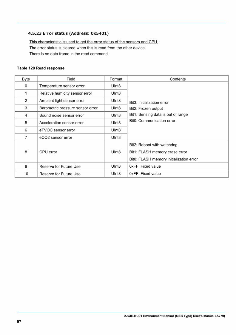
2JCIE-BU01 Environment Sensor (USB Type) User's Manual (A279) 97
4.5.23 Error status (Address: 0x5401)
This characteristic is used to get the error status of the sensors and CPU. The error status is cleared when this is read from the other device. There is no data frame in the read command.
Table 120 Read response
Byte Field Format Contents
0 Temperature sensor error UInt8
Bit3: Initialization error Bit2: Frozen output Bit1: Sensing data is out of range Bit0: Communication error
1 Relative humidity sensor error UInt8
2 Ambient light sensor error UInt8
3 Barometric pressure sensor error UInt8
4 Sound noise sensor error UInt8
5 Acceleration sensor error UInt8
6 eTVOC sensor error UInt8
7 eCO2 sensor error UInt8
8 CPU error UInt8
Bit2: Reboot with watchdog
Bit1: FLASH memory erase error
Bit0: FLASH memory initialization error
9 Reserve for Future Use UInt8 0xFF: Fixed value
10 Reserve for Future Use UInt8 0xFF: Fixed value
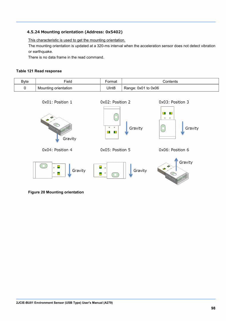
2JCIE-BU01 Environment Sensor (USB Type) User's Manual (A279) 98
4.5.24 Mounting orientation (Address: 0x5402)
This characteristic is used to get the mounting orientation. The mounting orientation is updated at a 320-ms interval when the acceleration sensor does not detect vibration or earthquake. There is no data frame in the read command.
Table 121 Read response
Byte Field Format Contents
0 Mounting orientation UInt8 Range: 0x01 to 0x06
Figure 20 Mounting orientation
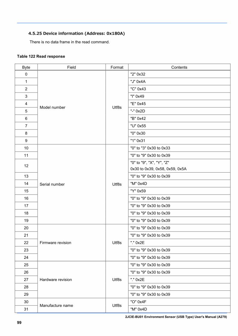
2JCIE-BU01 Environment Sensor (USB Type) User's Manual (A279) 99
4.5.25 Device information (Address: 0x180A)
There is no data frame in the read command.
Table 122 Read response
Byte Field Format Contents
0
Model number Utf8s
"2" 0x32
1 "J" 0x4A
2 "C" 0x43
3 "I" 0x49
4 "E" 0x45
5 "-" 0x2D
6 "B" 0x42
7 "U" 0x55
8 "0" 0x30
9 "1" 0x31
10
Serial number Utf8s
"0" to "3" 0x30 to 0x33
11 "0" to "9" 0x30 to 0x39
12 "0" to "9", "X", "Y", "Z" 0x30 to 0x39, 0x58, 0x59, 0x5A
13 "0" to "9" 0x30 to 0x39
14 "M" 0x4D
15 "Y" 0x59
16 "0" to "9" 0x30 to 0x39
17 "0" to "9" 0x30 to 0x39
18 "0" to "9" 0x30 to 0x39
19 "0" to "9" 0x30 to 0x39
20
Firmware revision Utf8s
"0" to "9" 0x30 to 0x39
21 "0" to "9" 0x30 to 0x39
22 "." 0x2E
23 "0" to "9" 0x30 to 0x39
24 "0" to "9" 0x30 to 0x39
25
Hardware revision Utf8s
"0" to "9" 0x30 to 0x39
26 "0" to "9" 0x30 to 0x39
27 "." 0x2E
28 "0" to "9" 0x30 to 0x39
29 "0" to "9" 0x30 to 0x39
30 Manufacture name Utf8s
"O" 0x4F
31 "M" 0x4D

2JCIE-BU01 Environment Sensor (USB Type) User's Manual (A279) 100
32 "R" 0x52
33 "O" 0x4F
34 "N" 0x4E
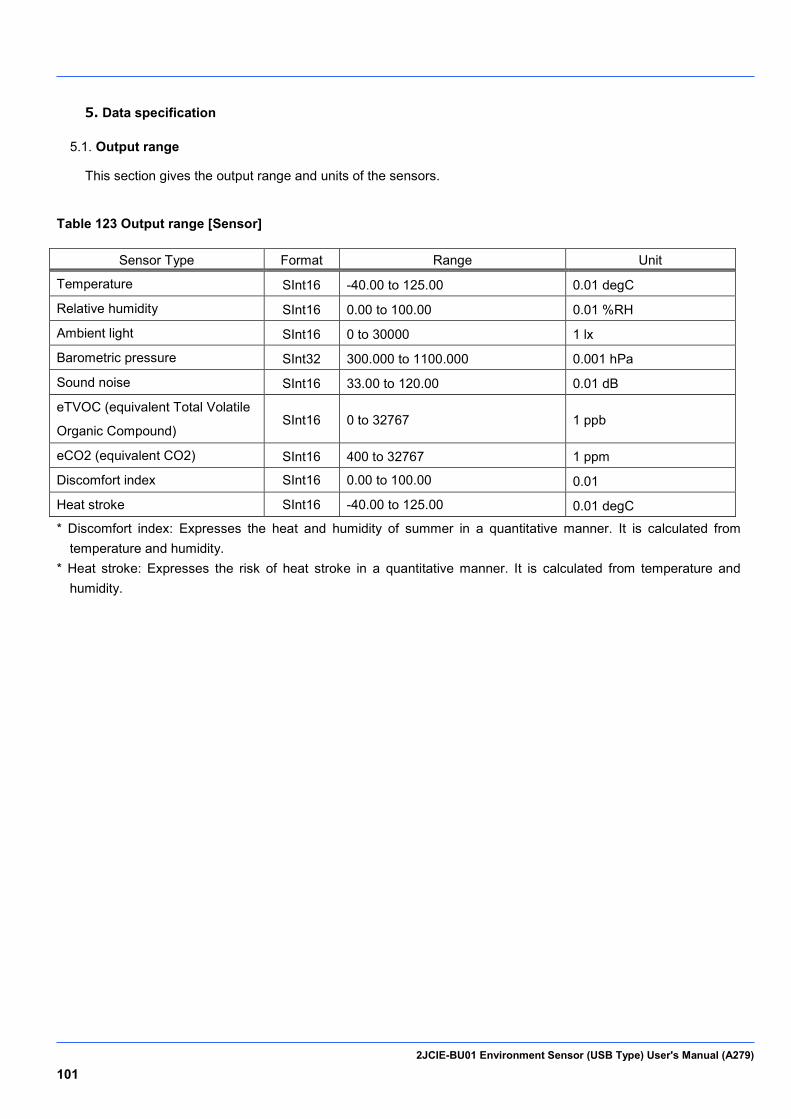
2JCIE-BU01 Environment Sensor (USB Type) User's Manual (A279) 101
5. Data specification
Output range 5.1.
This section gives the output range and units of the sensors.
Table 123 Output range [Sensor]
Sensor Type Format Range Unit
Temperature SInt16 -40.00 to 125.00 0.01 degC
Relative humidity SInt16 0.00 to 100.00 0.01 %RH
Ambient light SInt16 0 to 30000 1 lx
Barometric pressure SInt32 300.000 to 1100.000 0.001 hPa
Sound noise SInt16 33.00 to 120.00 0.01 dB
eTVOC (equivalent Total Volatile
Organic Compound) SInt16 0 to 32767 1 ppb
eCO2 (equivalent CO2) SInt16 400 to 32767 1 ppm
Discomfort index SInt16 0.00 to 100.00 0.01
Heat stroke SInt16 -40.00 to 125.00 0.01 degC
* Discomfort index: Expresses the heat and humidity of summer in a quantitative manner. It is calculated from temperature and humidity.
* Heat stroke: Expresses the risk of heat stroke in a quantitative manner. It is calculated from temperature and humidity.
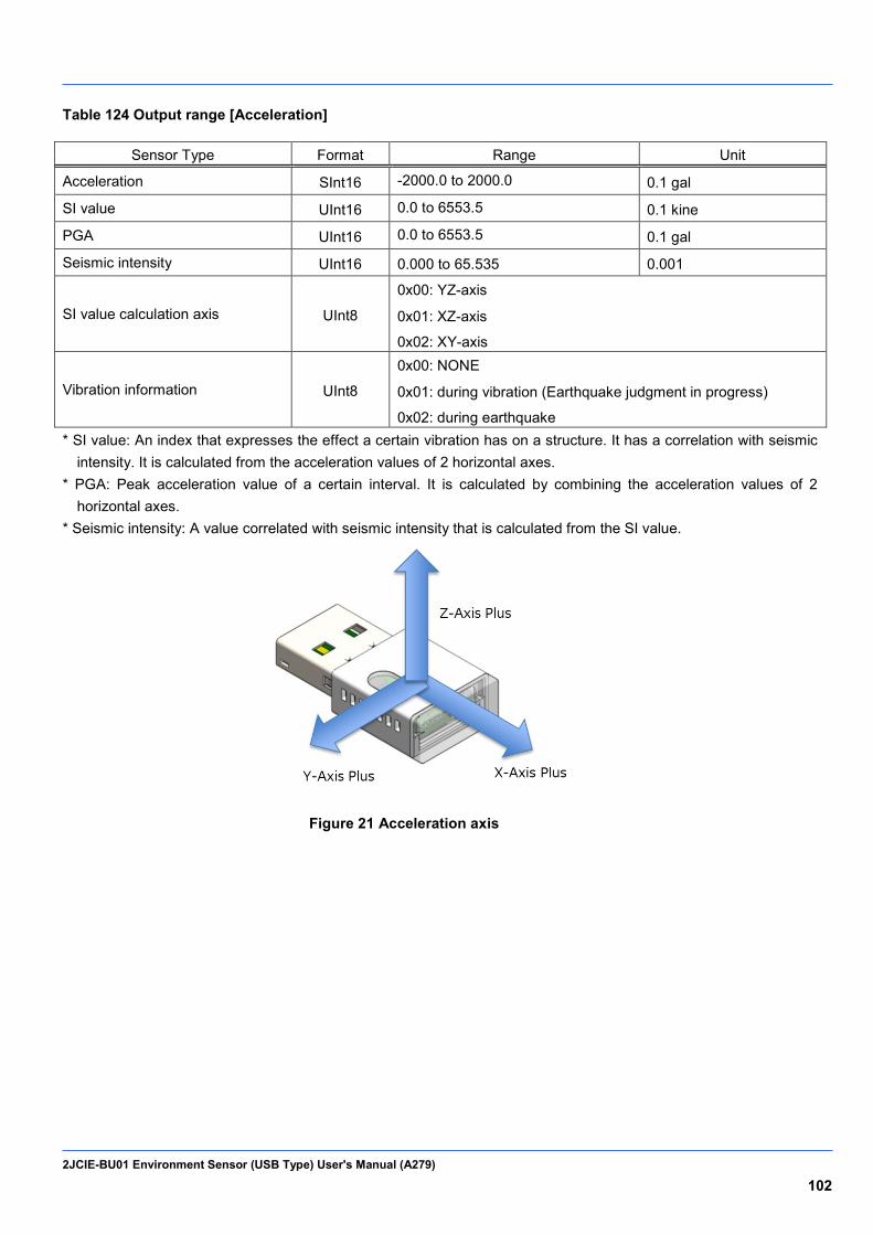
2JCIE-BU01 Environment Sensor (USB Type) User's Manual (A279) 102
Table 124 Output range [Acceleration]
Sensor Type Format Range Unit
Acceleration SInt16 -2000.0 to 2000.0 0.1 gal
SI value UInt16 0.0 to 6553.5 0.1 kine
PGA UInt16 0.0 to 6553.5 0.1 gal
Seismic intensity UInt16 0.000 to 65.535 0.001
SI value calculation axis UInt8
0x00: YZ-axis
0x01: XZ-axis
0x02: XY-axis
Vibration information UInt8
0x00: NONE
0x01: during vibration (Earthquake judgment in progress)
0x02: during earthquake * SI value: An index that expresses the effect a certain vibration has on a structure. It has a correlation with seismic
intensity. It is calculated from the acceleration values of 2 horizontal axes. * PGA: Peak acceleration value of a certain interval. It is calculated by combining the acceleration values of 2
horizontal axes. * Seismic intensity: A value correlated with seismic intensity that is calculated from the SI value.
Figure 21 Acceleration axis

2JCIE-BU01 Environment Sensor (USB Type) User's Manual (A279) 103
Event enable/disable 5.2.
Set the following bit fields to enable or disable the event flags.
Table 125 Event enable/disable [Sensor]
Bit Description Contents
0 Simple threshold [upper limit] 1
Set 1 to enable and set 0 to disable.
1 Simple threshold [upper limit] 2
2 Simple threshold [lower limit] 1
3 Simple threshold [lower limit] 2
4 Change threshold [rise] 1
5 Change threshold [rise] 2
6 Change threshold [decline] 1
7 Change threshold [decline] 2
8 Average value threshold [upper]
9 Average value threshold [lower]
10 Peak to Peak threshold [upper]
11 Peak to Peak threshold [lower]
12 Interval difference threshold [rise]
13 Interval difference threshold [decline]
14 Base difference threshold [upper]
15 Base difference threshold [lower]
Table 126 Event enable/disable [Acceleration]
Bit Description Contents
0 Simple threshold [upper limit] 1
Set 1 to enable and set 0 to disable. 1 Simple threshold [upper limit] 2
4 Change threshold [rise] 1
5 Change threshold [rise] 2

2JCIE-BU01 Environment Sensor (USB Type) User's Manual (A279) 104
Event flag 5.3.
The event flag detection results are output in the following bit fields.
Table 127 Event flag [Sensor]
Bit Description Contents
0 Simple threshold [upper limit] 1 This compares the sensor output and the threshold value and then judges whether above or equal to or below or equal to the threshold value.
1 Simple threshold [upper limit] 2
2 Simple threshold [lower limit] 1
3 Simple threshold [lower limit] 2
4 Change threshold [rise] 1 This compares the data measured last time and the data measured this time and then judges whether the change is above or equal to or below or equal to the threshold value.
5 Change threshold [rise] 2
6 Change threshold [decline] 1
7 Change threshold [decline] 2
8 Average value threshold [upper] This compares the sensor output average value and the threshold value and then judges whether above or equal to or below or equal to the threshold value. 9 Average value threshold [lower]
10 Peak to Peak threshold [upper] This compares the Peak to Peak of a specific period of sensor output and the threshold value and then judges whether above or equal to or below or equal to the threshold value. 11 Peak to Peak threshold [lower]
12 Interval difference threshold [rise] This compares the difference between the sensor output latest value
and the value of a specified number of times before and then judges
whether above or equal to or below or equal to the threshold value. 13 Interval difference threshold [decline]
14 Base difference threshold [upper] This compares the difference between the sensor output average
value and the value of a specified number of times before and then
judges whether above or equal to or below or equal to the threshold
value.
15
Base difference threshold [lower]
Table 128 Event flag [Acceleration]
Bit Description Contents
0 Simple threshold [upper limit] 1 This compares the sensor output and the threshold value and then judges whether above or equal to or below or equal to the threshold value.
1 Simple threshold [upper limit] 2
4 Change threshold [rise] 1 This compares the data measured last time and the data measured this time and then judges whether the change is above or equal to or below or equal to the threshold value.
5 Change threshold [rise] 2
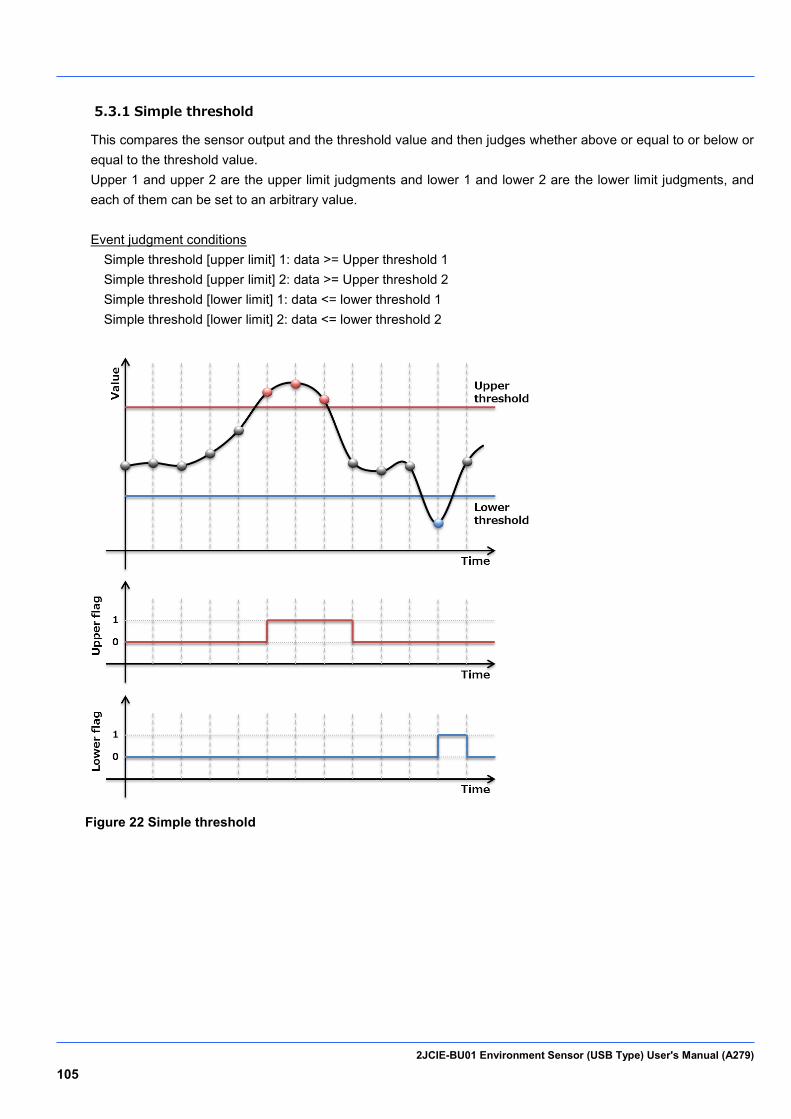
2JCIE-BU01 Environment Sensor (USB Type) User's Manual (A279) 105
5.3.1 Simple threshold
This compares the sensor output and the threshold value and then judges whether above or equal to or below or equal to the threshold value. Upper 1 and upper 2 are the upper limit judgments and lower 1 and lower 2 are the lower limit judgments, and each of them can be set to an arbitrary value. Event judgment conditions
Simple threshold [upper limit] 1: data >= Upper threshold 1 Simple threshold [upper limit] 2: data >= Upper threshold 2 Simple threshold [lower limit] 1: data <= lower threshold 1 Simple threshold [lower limit] 2: data <= lower threshold 2
Figure 22 Simple threshold

2JCIE-BU01 Environment Sensor (USB Type) User's Manual (A279) 106
5.3.2 Change threshold
This compares the data measured last time and the data measured this time and then judges whether the change is above or equal to or below or equal to the threshold value. Rise 1 and rise 2 are the rise judgments and decline 1 and decline 2 are the decline judgments, and each of them can be set to an arbitrary value. In the calculation formula, data[0] is the latest value and data[1] is the data of one measurement before (one second before). Event judgment conditions
Change threshold [rise] 1: (data[0] - data[1]) >= rise threshold 1 Change threshold [rise] 2: (data[0] - data[1]) >= rise threshold 2 Change threshold [decline] 1: (data[0] - data[1]) <= decline threshold 1 Change threshold [decline] 2: (data[0] - data[1]) <= decline threshold 2
Figure 23 Change threshold
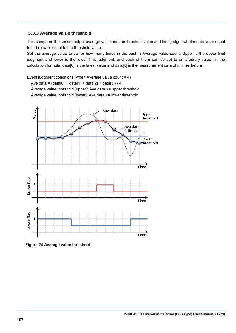
2JCIE-BU01 Environment Sensor (USB Type) User's Manual (A279) 107
5.3.3 Average value threshold
This compares the sensor output average value and the threshold value and then judges whether above or equal to or below or equal to the threshold value. Set the average value to be for how many times in the past in Average value count. Upper is the upper limit judgment and lower is the lower limit judgment, and each of them can be set to an arbitrary value. In the calculation formula, data[0] is the latest value and data[x] is the measurement data of x times before. Event judgment conditions (when Average value count = 4)
Ave data = (data[0] + data[1] + data[2] + data[3]) / 4 Average value threshold [upper]: Ave data >= upper threshold Average value threshold [lower]: Ave data <= lower threshold
Figure 24 Average value threshold
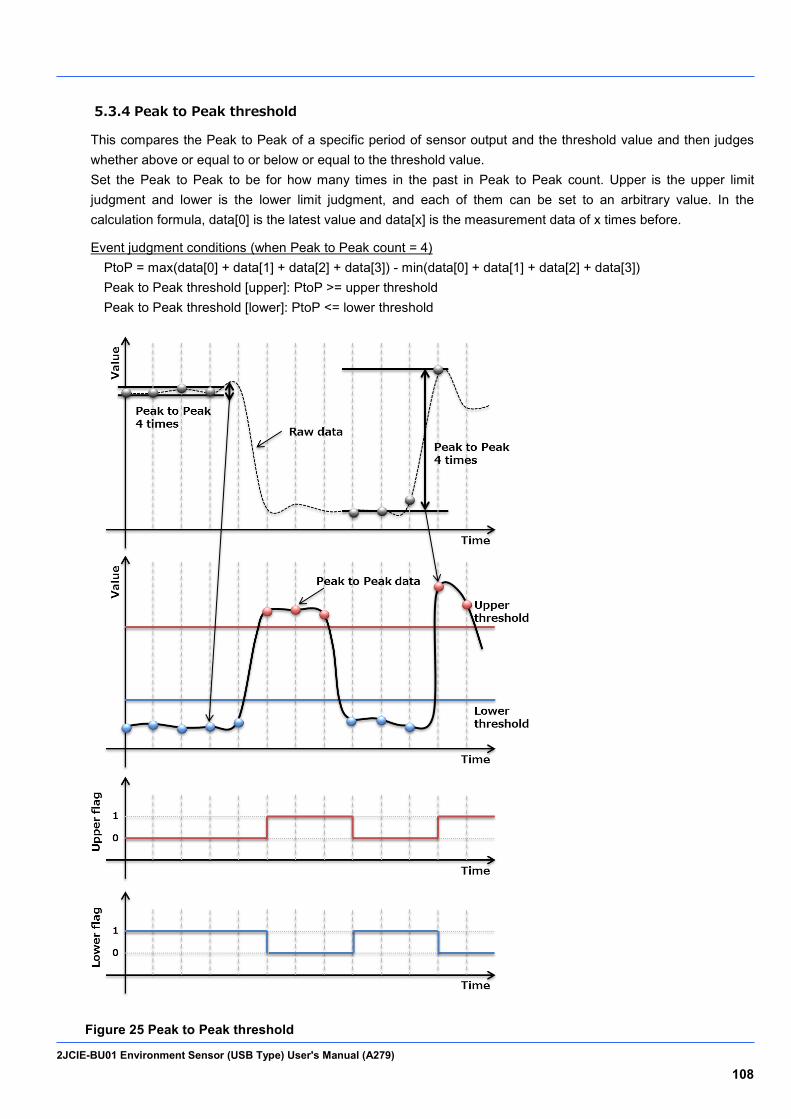
2JCIE-BU01 Environment Sensor (USB Type) User's Manual (A279) 108
5.3.4 Peak to Peak threshold
This compares the Peak to Peak of a specific period of sensor output and the threshold value and then judges whether above or equal to or below or equal to the threshold value. Set the Peak to Peak to be for how many times in the past in Peak to Peak count. Upper is the upper limit judgment and lower is the lower limit judgment, and each of them can be set to an arbitrary value. In the calculation formula, data[0] is the latest value and data[x] is the measurement data of x times before. Event judgment conditions (when Peak to Peak count = 4)
PtoP = max(data[0] + data[1] + data[2] + data[3]) - min(data[0] + data[1] + data[2] + data[3]) Peak to Peak threshold [upper]: PtoP >= upper threshold Peak to Peak threshold [lower]: PtoP <= lower threshold
Figure 25 Peak to Peak threshold
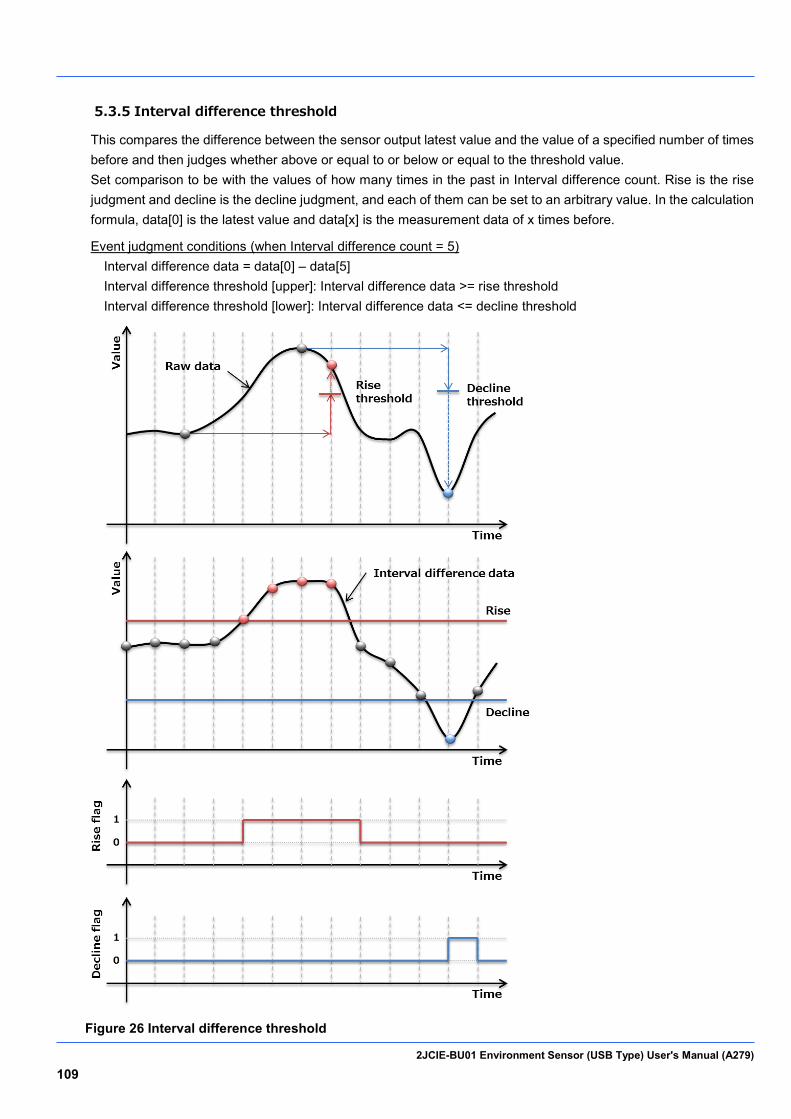
2JCIE-BU01 Environment Sensor (USB Type) User's Manual (A279) 109
5.3.5 Interval difference threshold
This compares the difference between the sensor output latest value and the value of a specified number of times before and then judges whether above or equal to or below or equal to the threshold value. Set comparison to be with the values of how many times in the past in Interval difference count. Rise is the rise judgment and decline is the decline judgment, and each of them can be set to an arbitrary value. In the calculation formula, data[0] is the latest value and data[x] is the measurement data of x times before. Event judgment conditions (when Interval difference count = 5)
Interval difference data = data[0] – data[5] Interval difference threshold [upper]: Interval difference data >= rise threshold Interval difference threshold [lower]: Interval difference data <= decline threshold
Figure 26 Interval difference threshold

2JCIE-BU01 Environment Sensor (USB Type) User's Manual (A279) 110
5.3.6 Base difference threshold
This compares the difference between the sensor output average value and the average value of a specified number of times before and then judges whether above or equal to or below or equal to the threshold value. Set comparison to be with the average value of how many times in the past in Base difference count. Rise is the rise judgment and decline is the decline judgment, and each of them can be set to an arbitrary value. In the calculation formula, ave data[0] is the latest value and ave data[x] is the measurement data of x times before. The value of Average value count is applied for the number of averaging times. Event judgment conditions (when Base difference count = 5 and Average value count = 4)
Base difference data = ave data[0] – ave data[5] Base difference threshold [upper]: Base difference data >= rise threshold Base difference threshold [lower]: Base difference data <= decline threshold
Figure 27 Base difference threshold

2JCIE-BU01 Environment Sensor (USB Type) User's Manual (A279) 111
Event threshold 5.4.
This section gives the threshold values of events.
Table 129 Event threshold [Temperature]
Temperature Format Default Range Unit
Simple threshold [upper limit] 1 SInt16 3500
0xF060 to 0x30D4 (-4000 to 12500)
0.01degC
Simple threshold [upper limit] 2 SInt16 4000
Simple threshold [lower limit] 1 SInt16 1000
Simple threshold [lower limit] 2 SInt16 0
Average value threshold [upper] SInt16 3500
Average value threshold [lower] SInt16 1000
Change threshold [rise] 1 SInt16 100
0x0000 to 0x2710 (0 to 10000)
Change threshold [rise] 2 SInt16 200
Change threshold [decline] 1 SInt16 100
Change threshold [decline] 2 SInt16 200
Peak to Peak threshold [upper] SInt16 100
Peak to Peak threshold [lower] SInt16 100
Interval difference threshold [rise] SInt16 100
Interval difference threshold [decline] SInt16 100
Base difference threshold [upper] SInt16 100
Base difference threshold [lower] SInt16 100
Average value count UInt8 8
0x01 to 0x08
(1 to 8) 1count
Peak to Peak count UInt8 8
Interval difference count UInt8 8
Base difference count UInt8 8
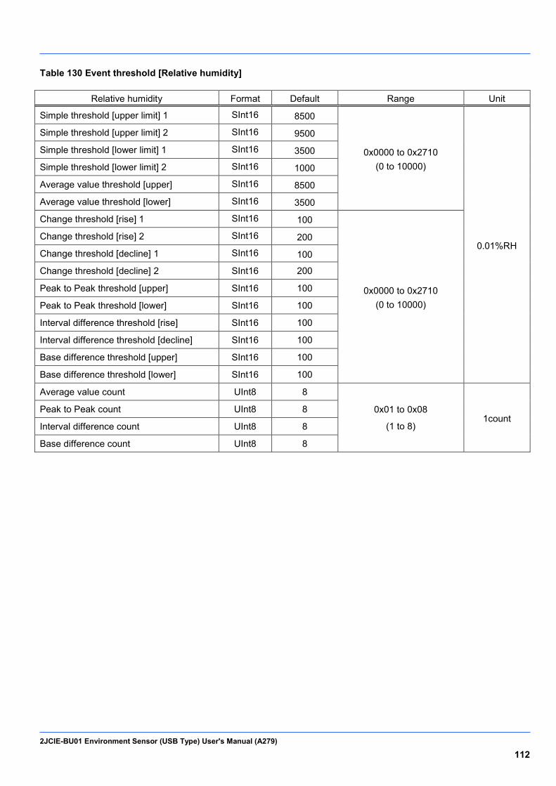
2JCIE-BU01 Environment Sensor (USB Type) User's Manual (A279) 112
Table 130 Event threshold [Relative humidity]
Relative humidity Format Default Range Unit
Simple threshold [upper limit] 1 SInt16 8500
0x0000 to 0x2710 (0 to 10000)
0.01%RH
Simple threshold [upper limit] 2 SInt16 9500
Simple threshold [lower limit] 1 SInt16 3500
Simple threshold [lower limit] 2 SInt16 1000
Average value threshold [upper] SInt16 8500
Average value threshold [lower] SInt16 3500
Change threshold [rise] 1 SInt16 100
0x0000 to 0x2710 (0 to 10000)
Change threshold [rise] 2 SInt16 200
Change threshold [decline] 1 SInt16 100
Change threshold [decline] 2 SInt16 200
Peak to Peak threshold [upper] SInt16 100
Peak to Peak threshold [lower] SInt16 100
Interval difference threshold [rise] SInt16 100
Interval difference threshold [decline] SInt16 100
Base difference threshold [upper] SInt16 100
Base difference threshold [lower] SInt16 100
Average value count UInt8 8
0x01 to 0x08
(1 to 8) 1count
Peak to Peak count UInt8 8
Interval difference count UInt8 8
Base difference count UInt8 8

2JCIE-BU01 Environment Sensor (USB Type) User's Manual (A279) 113
Table 131 Event threshold [Ambient light]
Ambient light Format Default Range Unit
Simple threshold [upper limit] 1 SInt16 300
0x0000 to 0x7530 (0 to 30000)
1lx
Simple threshold [upper limit] 2 SInt16 1000
Simple threshold [lower limit] 1 SInt16 100
Simple threshold [lower limit] 2 SInt16 10
Average value threshold [upper] SInt16 300
Average value threshold [lower] SInt16 100
Change threshold [rise] 1 SInt16 100
0x0000 to 0x7530 (0 to 30000)
Change threshold [rise] 2 SInt16 200
Change threshold [decline] 1 SInt16 100
Change threshold [decline] 2 SInt16 200
Peak to Peak threshold [upper] SInt16 100
Peak to Peak threshold [lower] SInt16 100
Interval difference threshold [rise] SInt16 100
Interval difference threshold [decline] SInt16 100
Base difference threshold [upper] SInt16 100
Base difference threshold [lower] SInt16 100
Average value count UInt8 8
0x01 to 0x08
(1 to 8) 1count
Peak to Peak count UInt8 8
Interval difference count UInt8 8
Base difference count UInt8 8
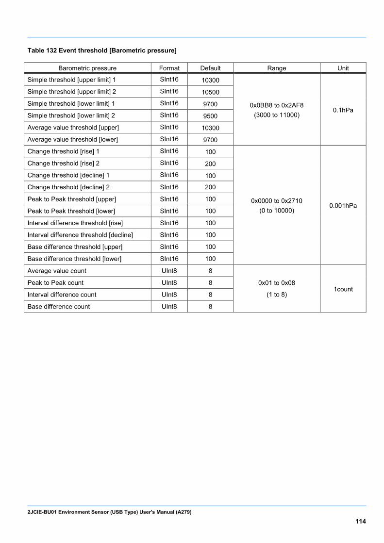
2JCIE-BU01 Environment Sensor (USB Type) User's Manual (A279) 114
Table 132 Event threshold [Barometric pressure]
Barometric pressure Format Default Range Unit
Simple threshold [upper limit] 1 SInt16 10300
0x0BB8 to 0x2AF8 (3000 to 11000)
0.1hPa
Simple threshold [upper limit] 2 SInt16 10500
Simple threshold [lower limit] 1 SInt16 9700
Simple threshold [lower limit] 2 SInt16 9500
Average value threshold [upper] SInt16 10300
Average value threshold [lower] SInt16 9700
Change threshold [rise] 1 SInt16 100
0x0000 to 0x2710 (0 to 10000)
0.001hPa
Change threshold [rise] 2 SInt16 200
Change threshold [decline] 1 SInt16 100
Change threshold [decline] 2 SInt16 200
Peak to Peak threshold [upper] SInt16 100
Peak to Peak threshold [lower] SInt16 100
Interval difference threshold [rise] SInt16 100
Interval difference threshold [decline] SInt16 100
Base difference threshold [upper] SInt16 100
Base difference threshold [lower] SInt16 100
Average value count UInt8 8
0x01 to 0x08
(1 to 8) 1count
Peak to Peak count UInt8 8
Interval difference count UInt8 8
Base difference count UInt8 8
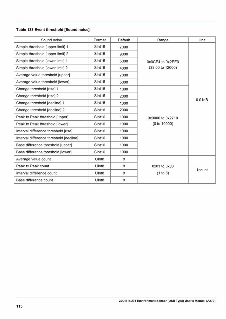
2JCIE-BU01 Environment Sensor (USB Type) User's Manual (A279) 115
Table 133 Event threshold [Sound noise]
Sound noise Format Default Range Unit
Simple threshold [upper limit] 1 SInt16 7000
0x0CE4 to 0x2EE0 (33.00 to 12000)
0.01dB
Simple threshold [upper limit] 2 SInt16 9000
Simple threshold [lower limit] 1 SInt16 5000
Simple threshold [lower limit] 2 SInt16 4000
Average value threshold [upper] SInt16 7000
Average value threshold [lower] SInt16 5000
Change threshold [rise] 1 SInt16 1000
0x0000 to 0x2710 (0 to 10000)
Change threshold [rise] 2 SInt16 2000
Change threshold [decline] 1 SInt16 1000
Change threshold [decline] 2 SInt16 2000
Peak to Peak threshold [upper] SInt16 1000
Peak to Peak threshold [lower] SInt16 1000
Interval difference threshold [rise] SInt16 1000
Interval difference threshold [decline] SInt16 1000
Base difference threshold [upper] SInt16 1000
Base difference threshold [lower] SInt16 1000
Average value count UInt8 8
0x01 to 0x08
(1 to 8) 1count
Peak to Peak count UInt8 8
Interval difference count UInt8 8
Base difference count UInt8 8
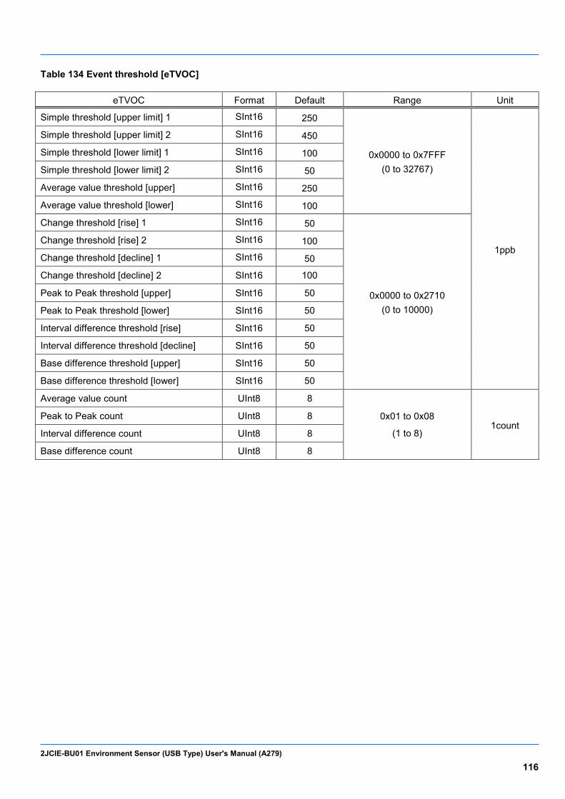
2JCIE-BU01 Environment Sensor (USB Type) User's Manual (A279) 116
Table 134 Event threshold [eTVOC]
eTVOC Format Default Range Unit
Simple threshold [upper limit] 1 SInt16 250
0x0000 to 0x7FFF (0 to 32767)
1ppb
Simple threshold [upper limit] 2 SInt16 450
Simple threshold [lower limit] 1 SInt16 100
Simple threshold [lower limit] 2 SInt16 50
Average value threshold [upper] SInt16 250
Average value threshold [lower] SInt16 100
Change threshold [rise] 1 SInt16 50
0x0000 to 0x2710 (0 to 10000)
Change threshold [rise] 2 SInt16 100
Change threshold [decline] 1 SInt16 50
Change threshold [decline] 2 SInt16 100
Peak to Peak threshold [upper] SInt16 50
Peak to Peak threshold [lower] SInt16 50
Interval difference threshold [rise] SInt16 50
Interval difference threshold [decline] SInt16 50
Base difference threshold [upper] SInt16 50
Base difference threshold [lower] SInt16 50
Average value count UInt8 8
0x01 to 0x08
(1 to 8) 1count
Peak to Peak count UInt8 8
Interval difference count UInt8 8
Base difference count UInt8 8
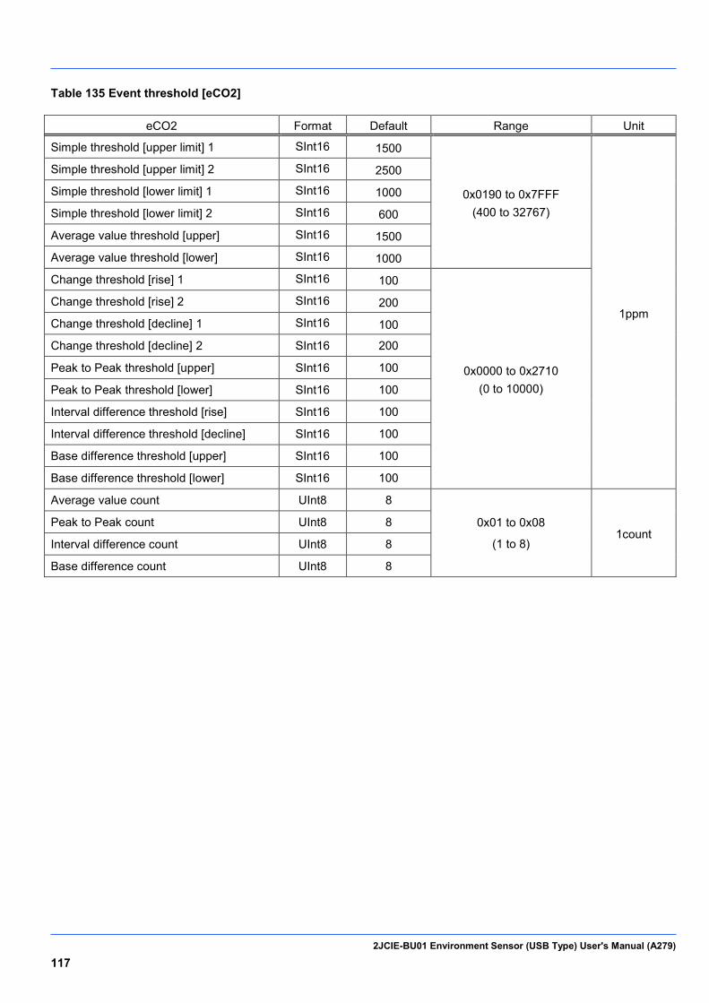
2JCIE-BU01 Environment Sensor (USB Type) User's Manual (A279) 117
Table 135 Event threshold [eCO2]
eCO2 Format Default Range Unit
Simple threshold [upper limit] 1 SInt16 1500
0x0190 to 0x7FFF (400 to 32767)
1ppm
Simple threshold [upper limit] 2 SInt16 2500
Simple threshold [lower limit] 1 SInt16 1000
Simple threshold [lower limit] 2 SInt16 600
Average value threshold [upper] SInt16 1500
Average value threshold [lower] SInt16 1000
Change threshold [rise] 1 SInt16 100
0x0000 to 0x2710 (0 to 10000)
Change threshold [rise] 2 SInt16 200
Change threshold [decline] 1 SInt16 100
Change threshold [decline] 2 SInt16 200
Peak to Peak threshold [upper] SInt16 100
Peak to Peak threshold [lower] SInt16 100
Interval difference threshold [rise] SInt16 100
Interval difference threshold [decline] SInt16 100
Base difference threshold [upper] SInt16 100
Base difference threshold [lower] SInt16 100
Average value count UInt8 8
0x01 to 0x08
(1 to 8) 1count
Peak to Peak count UInt8 8
Interval difference count UInt8 8
Base difference count UInt8 8

2JCIE-BU01 Environment Sensor (USB Type) User's Manual (A279) 118
Table 136 Event threshold [Discomfort index]
Discomfort index Format Default Range Unit
Simple threshold [upper limit] 1 SInt16 7500
0x0000 to 0x2710 (0 to 10000)
0.01
Simple threshold [upper limit] 2 SInt16 8000
Simple threshold [lower limit] 1 SInt16 6000
Simple threshold [lower limit] 2 SInt16 5500
Average value threshold [upper] SInt16 7500
Average value threshold [lower] SInt16 6000
Change threshold [rise] 1 SInt16 200
0x0000 to 0x2710 (0 to 10000)
Change threshold [rise] 2 SInt16 500
Change threshold [decline] 1 SInt16 200
Change threshold [decline] 2 SInt16 500
Peak to Peak threshold [upper] SInt16 200
Peak to Peak threshold [lower] SInt16 200
Interval difference threshold [rise] SInt16 200
Interval difference threshold [decline] SInt16 200
Base difference threshold [upper] SInt16 200
Base difference threshold [lower] SInt16 200
Average value count UInt8 8
0x01 to 0x08
(1 to 8) 1count
Peak to Peak count UInt8 8
Interval difference count UInt8 8
Base difference count UInt8 8
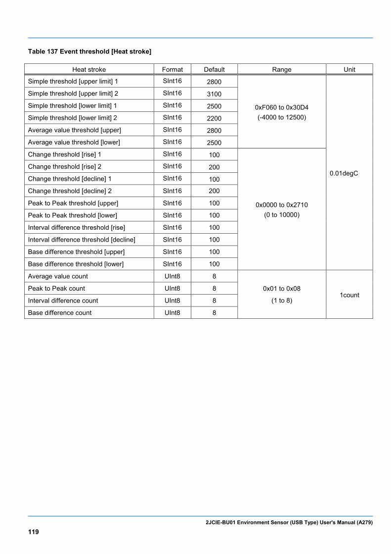
2JCIE-BU01 Environment Sensor (USB Type) User's Manual (A279) 119
Table 137 Event threshold [Heat stroke]
Heat stroke Format Default Range Unit
Simple threshold [upper limit] 1 SInt16 2800
0xF060 to 0x30D4 (-4000 to 12500)
0.01degC
Simple threshold [upper limit] 2 SInt16 3100
Simple threshold [lower limit] 1 SInt16 2500
Simple threshold [lower limit] 2 SInt16 2200
Average value threshold [upper] SInt16 2800
Average value threshold [lower] SInt16 2500
Change threshold [rise] 1 SInt16 100
0x0000 to 0x2710 (0 to 10000)
Change threshold [rise] 2 SInt16 200
Change threshold [decline] 1 SInt16 100
Change threshold [decline] 2 SInt16 200
Peak to Peak threshold [upper] SInt16 100
Peak to Peak threshold [lower] SInt16 100
Interval difference threshold [rise] SInt16 100
Interval difference threshold [decline] SInt16 100
Base difference threshold [upper] SInt16 100
Base difference threshold [lower] SInt16 100
Average value count UInt8 8
0x01 to 0x08
(1 to 8) 1count
Peak to Peak count UInt8 8
Interval difference count UInt8 8
Base difference count UInt8 8
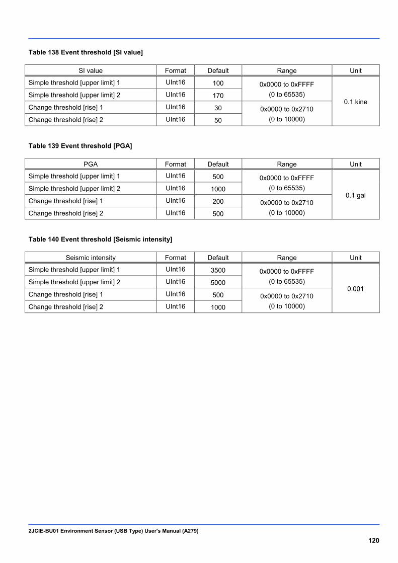
2JCIE-BU01 Environment Sensor (USB Type) User's Manual (A279) 120
Table 138 Event threshold [SI value]
SI value Format Default Range Unit
Simple threshold [upper limit] 1 UInt16 100 0x0000 to 0xFFFF (0 to 65535)
0.1 kine Simple threshold [upper limit] 2 UInt16 170
Change threshold [rise] 1 UInt16 30 0x0000 to 0x2710 (0 to 10000) Change threshold [rise] 2 UInt16 50
Table 139 Event threshold [PGA]
PGA Format Default Range Unit
Simple threshold [upper limit] 1 UInt16 500 0x0000 to 0xFFFF (0 to 65535)
0.1 gal Simple threshold [upper limit] 2 UInt16 1000
Change threshold [rise] 1 UInt16 200 0x0000 to 0x2710 (0 to 10000) Change threshold [rise] 2 UInt16 500
Table 140 Event threshold [Seismic intensity]
Seismic intensity Format Default Range Unit
Simple threshold [upper limit] 1 UInt16 3500 0x0000 to 0xFFFF (0 to 65535)
0.001 Simple threshold [upper limit] 2 UInt16 5000
Change threshold [rise] 1 UInt16 500 0x0000 to 0x2710 (0 to 10000) Change threshold [rise] 2 UInt16 1000

Please check each region's Terms & Conditions by region website.
OMRON CorporationElectronic and Mechanical Components Company
Regional Contact
Cat. No. A279-E1-010618 (0618)(O)
Americas Europehttps://www.components.omron.com/ http://components.omron.eu/
Asia-Pacific China https://ecb.omron.com.sg/ https://www.ecb.omron.com.cn/
Korea Japanhttps://www.omron-ecb.co.kr/ https://www.omron.co.jp/ecb/
In the interest of product improvement, specifications are subject to change without notice. © OMRON Corporation 2018 All Rights Reserved.