Embed Size (px)
Citation preview

DIRECTIONS FOR USE
1553-BZA 108 35 Uen Rev B 2007-01-19
1(27)
POWER SUPPLY SYSTEM NetSure™ 501, BZA 108 35, –48 V DC
© Emerson Network Power Energy Systems AB 2007 – All rights reserved

DIRECTIONS FOR USE – BZA 108 35
1553-BZA 108 35 Uen Rev 2007-01-19
2(27)
The contents of this document are subject to revision without notice due to continued progress in methodology, design, and manufacturing.
Emerson Network Power Energy Systems AB
SE – 141 82 Stockholm Sweden
Tel. +46 8 721 6000 Fax. +46 8 721 7177 www.emersonenergy.com

DIRECTIONS FOR USE – BZA 108 35
1553-BZA 108 35 Uen Rev 2007-01-19
3(27)
Contents 1 Introduction 4
2 Function 4
3 Configurations 5
4 Units in the system 8 4.1 Rectifier 8 4.2 Rectifier subrack 10 4.3 Control units 11 4.4 Multifunction unit 11 4.5 AC distribution 12 4.6 AC connection terminals 12 5 Technical data 13 5.1 System 13 5.2 Cabinet 13 5.3 Rectifier 13 6 Installation 14
7 Start-up and installation test 14
8 Maintenance 14 8.1 Safety 14 8.2 Scheduled maintenance 14 8.3 Alarms 15 8.4 Fault symptoms and trouble shooting 15 9 Exchange of units and parts 21 9.1 Exchange of rectifiers 21 9.2 Rectifier fan replacement 22 9.3 Exchange of distribution circuit-breaker 23 9.4 Exchange of contactor 24 9.5 Exchange of SCU/ACU 25 9.6 Exchange of connector board 25 9.7 Exchange of SCU/ACU supply fuses 26 10 Abbreviations used in this document 27
DIRECTIONS FOR USE – BZA 108 35
1553-BZA 108 35 Uen Rev 2007-01-19
4(27)
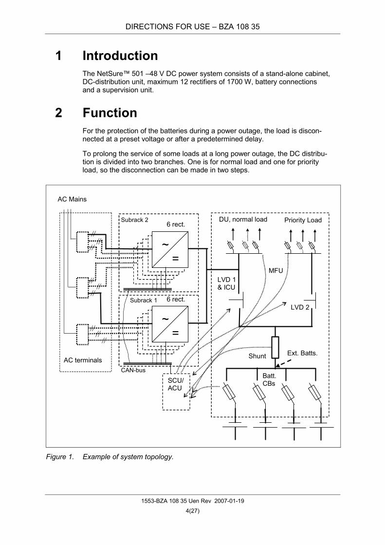
1 Introduction The NetSure™ 501 –48 V DC power system consists of a stand-alone cabinet, DC-distribution unit, maximum 12 rectifiers of 1700 W, battery connections and a supervision unit.
2 Function For the protection of the batteries during a power outage, the load is discon-nected at a preset voltage or after a predetermined delay.
To prolong the service of some loads at a long power outage, the DC distribu-tion is divided into two branches. One is for normal load and one for priority load, so the disconnection can be made in two steps.
~ =
DU, normal load Priority Load
SCU/ACU
CAN-bus
AC Mains
LVD 1& ICU
LVD 2
Batt. CBs
AC terminals
~ =
6 rect.
Shunt
Subrack 1
Subrack 2
6 rect.
Ext. Batts.
MFU
Figure 1. Example of system topology.

DIRECTIONS FOR USE – BZA 108 35
1553-BZA 108 35 Uen Rev 2007-01-19
5(27)
3 Configurations The cabinets can be configured with different numbers of rectifiers, battery- and distribution- circuit-breakers. They are built for overhead cabling.
Figure 2. Example of configuration with overhead cabling.
AC distribution unit (optional)
Rectifier subrack
MFU and Control unit
Rectifier subrack
Extension distribution unit

DIRECTIONS FOR USE – BZA 108 35
1553-BZA 108 35 Uen Rev 2007-01-19
6(27)
The Figure 3 and Figure 4 give examples of standard configurations.
Cover panel 2 UAC terminals (if no ACD)MFU (battery CBs, S/ALVDs, normal and C/Cprio load CBs U/UR R R R R R
ACD (optional)(BMG 653 39/21)Fire trap
Figure 3. Configuration with single rectifier subrack.
Cover panel 2 UAC teminals (if no ACD)Extension distribution CBs(normal load)
Cover panel 2 U
MFU (battery CBs, S/ALVDs, normal and C/Cprio load CBs) U/UR R R R R R
R R R R R R
ACD (option)(BMG 653 39/22)Fire trap
Figure 4. Configuration with double rectifier subracks.

DIRECTIONS FOR USE – BZA 108 35
1553-BZA 108 35 Uen Rev 2007-01-19
7(27)
Basic configuration: • Cabinet for overhead cabling • Maximum 12 rectifiers 1700 W • One or two rectifier subracks for maximum 6 rectifiers each • MFU including maximum four battery CBs, distribution CBs, LVD contac-
tors, a standard control unit (SCU) and a battery shunt • AC terminal unit for maximum 12 rectifiers
• Battery temperature sensor KET 103 06/1
Options:
• Advanced control unit (ACU) • Cables for battery, distribution, earthing and signalling • Cabling materials (lugs, tie wraps, markings) • Internal AC distribution unit for maximum 12 rectifiers • External AC distribution units • Mains cable • Lifting eye bolts SAR 201 080/03 • Cabinet anchoring material BMY 107 125/1 • AC inlet pull-relief clamps • Room temperature sensor KET 103 06/1 • Spare parts

DIRECTIONS FOR USE – BZA 108 35
1553-BZA 108 35 Uen Rev 2007-01-19
8(27)
4 Units in the system
4.1 Rectifier The rectifier is voltage regulated of a constant power limitation type (1700 W) and designed to meet the most stringent electrical requirements as well as demands for high power density (fan cooling). It can work independently of the control unit, and can share the load actively and control the system voltage.
Figure 5. Rectifier.
4.1.1 LEDs The front panel has three indicator LEDs. The functions of the LEDs are listed in the table below.
LED Normal Abnormal Cause of Abnormality
OFF No AC Mains Supply Power indicator (green) ON
Flashing Rectifier is under control by SCU/ACU
ON AC input over/undervoltage, PFC over/undervoltage and over-temperature
Protection indica-tor (yellow) OFF
Flashing Communication with SCU/ACU failure
ON Output overvoltage Alarm indicator (red) OFF
Flashing Fan Failure
LEDs

DIRECTIONS FOR USE – BZA 108 35
1553-BZA 108 35 Uen Rev 2007-01-19
9(27)
4.1.2 Features
• Hot swappable. The rectifier is plug-and-play to live inputs and outputs.
• Active load sharing. The rectifier uses advanced digital active load sharing technology for minimum load difference between units.
• Power derating by input voltage. The rectifier will go into power derated mode if the input AC voltage is too low or too high.
• Power derating by output load. The rectifier will limit its output power con-stant when the load exceeds the nominal output power.
• Power derating by temperature. For high temperatures the output load will be gradually reduced. See technical data.
• Current limiting function. The rectifier has a current limiting function. The current limit can be set from an SCU/ACU.
• Foldback current limiting function. If a short circuit occurs on the rectifier output terminals, the rectifier will keep its output current at a constant value. When the short circuit fault is cleared, the rectifier will automatically restore to normal operation.
• Adjustable output voltage. The voltage can be set from an SCU/ACU.
• Current walk-in. The rectifier can be set from an SCU/ACU to take load gradually in order to reduce the stress on generators, fuses etc.
• Fan control. The fan’s speed is controlled according to the rectifier internal temperature. The fan is stopped completely at low temperature and at very low or high input voltage.
4.1.3 Digital Signal Processor (DSP) The rectifier has a built-in advanced DSP that monitors and controls the operation of the rectifier. The DSP also communicates with an SCU/ACU through a CAN bus.
• The rectifier can receive commands such as turning on/off, current walk-in on/off signal and high voltage alarm reset signal from an SCU/ACU.
• An SCU/ACU can adjust the output voltage, overvoltage alarm point, cur-rent walk-in time and the current limit of the rectifier.
• The rectifier reports its output voltage, output current, temperature, current limit setpoint, overvoltage setpoint, on/off status and alarm information to an SCU/ACU in real time.
• By querying the DSP, an SCU/ACU can get the following data from the rectifier: Input voltage, output voltage, output current, current limit setpoint, temperature of rectifier, and overvoltage setpoint.

DIRECTIONS FOR USE – BZA 108 35
1553-BZA 108 35 Uen Rev 2007-01-19
10(27)
• By querying the DSP, an SCU/ACU can get the following state information from the rectifier: On/off, protect (input protect, inner DC bus voltage pro-tect; overtemperature), fault (HVSD, fan failure), thermal derating, AC derating, AC failure, and unbalance current.
• An SCU/ACU can get the following unit information from the rectifier: Ad-dress, code, date, SW version and HW version.
4.1.4 Protection functions
• Input over/undervoltage protection. The rectifier will shut down and its yel-low LED will emit light if the input voltage is outside the range 80 to 305 V AC. An alarm will be sent to the SCU/ACU.
• Output overvoltage protection. If the rectifier output voltage exceeds a limit that can be set from the SCU/ACU, the rectifier will shut down. If output over voltage occurs two times within 5 minutes, the rectifier can only be restarted manually and its red alarm LED will emit light. An alarm will be sent to the SCU/ACU.
• Over-temperature protection. The rectifier will limit its power to 50% of rated output power if its internal temperature is higher than 75 °C. If the in-ternal temperature reaches 80 °C, the rectifier will shut down and its yel-low LED will emit light. An alarm will be sent to the SCU/ACU. The alarm will cease and the rectifier will restart when the temperature be-comes normal.
• Communication failure. At communication failure, the rectifier output volt-age is reduced to a default value for protection of the battery. The yellow LED will flash and alarm will be sent to the SCU/ACU.
• Fan alarm. The red LED will flash at a fan fault and the rectifier will stop.
• Unbalance of Rectifier Output Current. When the output current of the rec-tifiers in a DC power system is unbalanced, the rectifier that outputs un-balanced current will be identified automatically and its yellow LED will emit light. An alarm will be sent to the SCU/ACU.
4.2 Rectifier subrack
Figure 6. Subrack for six rectifiers.
The rectifier subrack has space for six rectifiers.

DIRECTIONS FOR USE – BZA 108 35
1553-BZA 108 35 Uen Rev 2007-01-19
11(27)
4.3 Control units The control unit is placed in the multifunction unit. It controls, supervises and communicates with the other units of the power supply system and manages alarm handling, etc.
Two control units are available. The standard control unit (SCU) has an LCD-display, offers internal supervision and alarm handling, sends external alarm signals over relays and communicates externally via modem with external computer-based supervision systems (EEM, for example) that can be imple-mented for different maintenance activities.
The advanced control unit (ACU) has, in addition to the SCU features, an in-terface to communicate with supervision modules (SM) for supervision of existing cabinets, AC mains and batteries, for example. It has a Web interface for communication with MS Explorer.
For detailed information, refer to USER’S GUIDE 5/1553-BMP 903 050 Uen, for the ACU and 5/1553-BMP 903 051 Uen, for the SCU.
4.4 Multifunction unit
Figure 7. MFU.
The unit combines normal and priority distribution circuit-breakers battery CBs, a battery shunt (500 A) and one or two load disconnect contactors (125 and 500 A). The control unit (SCU/ACU) and the connector board are also mounted here.
LVD contactors
Connector board
DIN bar for CBs
+ terminals CB alarm board
DIRECTIONS FOR USE – BZA 108 35
1553-BZA 108 35 Uen Rev 2007-01-19
12(27)
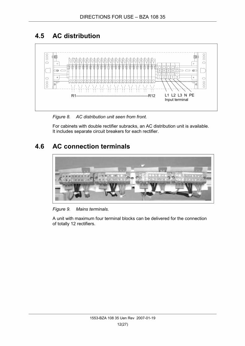
4.5 AC distribution
R1--------------------------------------------------------R12 L1 L2 L3 N PE Input terminal
Figure 8. AC distribution unit seen from front.
For cabinets with double rectifier subracks, an AC distribution unit is available. It includes separate circuit breakers for each rectifier.
4.6 AC connection terminals
Figure 9. Mains terminals.
A unit with maximum four terminal blocks can be delivered for the connection of totally 12 rectifiers.

DIRECTIONS FOR USE – BZA 108 35
1553-BZA 108 35 Uen Rev 2007-01-19
13(27)
5 Technical data
5.1 System Nominal DC voltage –48 V
Maximum output current @ 48 V 212 A (with one rectifier subrack) or 425 A (with two rectifier subracks)
Operational temperature –5 to +45 °C (with hydraulic magnetic circuit-breakers)
–5 to +30 °C (with thermal/electro magnetic circuit-breakers)
Storage temperature –40 to +75 °C
Relative humidity 5 to 90%
5.2 Cabinet Building practice 23”
Height (incl. top cover and feet) 1250, 1650, 1850, 2050 mm
Footprint (with x depth) 400 or 600 x 600 mm
Weight (fully equipped, without batteries) maximum 150 kg
5.3 Rectifier See data sheet EN/LZT 145 280 RA

DIRECTIONS FOR USE – BZA 108 35
1553-BZA 108 35 Uen Rev 2007-01-19
14(27)
6 Installation See INSTALLATION INSTRUCTIONS 1531-BZA 108 35 Uen.
7 Start-up and installation test See TEST INSTRUCTIONS 1532-BZA 108 35 Uen.
8 Maintenance Adequate knowledge of the power supply system is required. Refer to item 1 to 5 of this document.
8.1 Safety The document SAFETY RULES 1550-1004 and local safety rules shall be fol-lowed when doing maintenance work in the power supply equipment. Meas-ures that require work inside the cabinets or intervention in a unit shall always be carried out by adequately trained personnel with adequate knowledge of the power supply system. When in doubt about an action or how to carry it out, always call for adequately trained personnel.
In case it is necessary to work on a live power supply system, the approval for this type of work must be given, based on local regulations governing for ex-ample the following areas:
• General rules for work on live equipment
• Certification of operatives conducted by certified supervisor
• Approved tools
• Customer approval
8.2 Scheduled maintenance • Use a vacuum cleaner to remove dust from the air inlets of the cabinets.
• Check and test the batteries according to the recommendations of the bat-tery supplier.
• A scheduled performance test according to the following table shall be performed at least every two years according to item “Test of signals and supervision” in the document TEST INSTRUCTIONS 1532-BZA 108 35 Uen. Settings according to the document TABLE OF SET VALUES, shall be verified in this test.
A copy of the test result shall be kept in the logbook of the plant.

DIRECTIONS FOR USE – BZA 108 35
1553-BZA 108 35 Uen Rev 2007-01-19
15(27)
8.3 Alarms
8.3.1 Alarm categories The different alarm categories used in the power supply system are Critical, Major, Observation and No Alarm.
An alarm of category Critical requires immediate action, whatever the time of day or night.
An alarm of category Major requires immediate action if it occurs during work-ing-hours, otherwise as soon as the working-hours commence.
An alarm of category Observation is an alarm that indicates a temporary state of operation and does not normally require any action. However, if the alarm persists for more than 20 hours, it must be investigated.
If an alarm has category No Alarm it means that the alarm is deactivated and will not be shown in the display of the SCU/ACU.
8.3.2 Procedure in case of alarm Enter in the logbook of the power supply system all observations made at the moment of failure, such as date, time, system voltage and rectifier load. Enter also what alarm(s) are shown and any external disturbance such as thunder-storm or mains failure.
Trace activated alarms by means of the alarm survey of the respective unit and the item, which describes what actions to take on the respective alarm.
8.4 Fault symptoms and trouble shooting
8.4.1 System alarms For system alarms, see USER’S GUIDE 1553-BMP 903 051 Uen for the SCU and 1553-BMP 903 050 Uen for the ACU.
Alarm on the SCU display
Alarm on the ACU display
Cause Suggestion
Alarms Blocked
Alarm Blocked
The outgoing alarms are blocked from the SCU/ACU.
Check why before reconnecting the alarms.
Load Fuse Alarm
Fuse Alarm One or more distribution circuit-breakers for the load have tripped.
Find out and eliminate the reason for the tripped circuit breaker before resetting it.
Check the connectors and cables for the CAN loop.
Exchange the rectifier that does not respond.
Rect Not Respond
CAN Comm Fault
There CAN communica-tion is broken.
Exchange the SCU/ACU.

DIRECTIONS FOR USE – BZA 108 35
1553-BZA 108 35 Uen Rev 2007-01-19
16(27)
Alarm on the SCU display
Alarm on the ACU display
Cause Suggestion
If there is a mains failure, check that it is not caused by broken supply fuses.
LVD 1 LVD 1 Dis-connected
The contactor for the nor-mal load is open because the battery is too deep discharged. The batteries are discon-nected at a preset level, in order to protect them from over-discharging.
If the rectifiers are working, the problem may be that the system load is higher than the rectifier capacity, causing the batteries to discharge. If this is the reason, install more rectifiers.
LVD 2 LVD 2 Dis-connected
The contactor for the pri-oritised load is open be-cause the battery is too deep discharged.
See LVD 1
LVD 1/ LVD 2 Open
Contactor Fault
An LVD contactor is in a wrong state.
Check the contactor functions.
Batt Curr High
Abnorm Bat Curr
The boost charging cur-rent exceeds the set max. value.
Check the settings.
Indicates that one or more battery fuses/circuit break-ers have blown/tripped or been removed.
If a battery fuse/circuit breaker has been removed/tripped manually, check with the person that removed/tripped it before rein-serting/resetting it. Ensure that there is no fault before doing that. The battery fuse shall be reinserted by adequately trained personnel.
Batt Fuse Alarm
Fuse Alarm
If the battery fuse/circuit breaker is blown/tripped, the reason for the failure probably is overload or short circuit.
Find out and eliminate the reason for the blown/tripped fuse/circuit breaker before swapping/resetting it.
Self-detect Err
ACU fault SCU/ACU failure. Exchange the SCU/ACU.
Manual Mode
Manual Mode
The battery monitoring has been set to “Manual mode” in the SCU/ACU.
Check why before resetting it to automatic.
The system is not in Float Charge mode because of:
The boost charge is ac-tive.
The boost charge will stop automatically.
Non-Float Status
The battery test is active. The discharge test will stop automatically.
The battery test is active. The discharge test will stop automatically.
There is a mains failure. Check that it is not caused by broken supply fuses.
Batt Dis-charge
The system load is higher than the rectifier capacity, causing the batteries to discharge.
Install more rectifiers.

DIRECTIONS FOR USE – BZA 108 35
1553-BZA 108 35 Uen Rev 2007-01-19
17(27)
Alarm on the SCU display
Alarm on the ACU display
Cause Suggestion
Curr Dis-crepancy
Dis Curr Im The currents from two groups of batteries are not equal. Note: There must be two
battery shunts in the system to acti-vate this function.
Check the batteries.
Short Test Fail The short time battery test
has failed. Check the batteries.
Check the float charging level.
Check that the load is lower than the capac-ity of the rectifiers.
Batt Test Fail
Test Failure The battery test has failed.
Check the battery according to the recom-mendations of the supplier.
Volt Dis-crepancy
Rect Over Volt
Rectifier overvoltage See item 8.4.2
Mains Fail-ure
Mains Fail-ure
All rectifiers have stopped. Check if there is a general mains failure. Check that it is not caused by broken supply fuses.
Multi-Rect Alarm
Multi-rect fail Two or more rectifiers have stopped.
See item 8.4.2
Maintain Alarm
Mainte-nance Alrm
The maintenance timer gives alarm
Check the settings of the Maintenance Time Delay
Rectifier Lost
Rectifier Lost
The SCU/ACU has de-tected a reduction in the number of running rectifi-ers.
See item 8.4.2 If the lost rectifier is to be removed perma-nently, the alarm must be reset from the SCU/ACU.
Load share Alarm
The output current of a rectifier is outside the av-erage value for all rectifi-ers.
Check the rectifiers.
Check the rectifier HVSD setting. Rect HVSD A rectifier output voltage was higher than the recti-fier HVSD setting and has shut down. Replace the rectifier.
Rect AC Fail Rect AC Failure
AC input voltage outside the normal range.
See item 8.4.2
Rect Over Temp
Rectifier overtemperature protection.
See item 8.4.2
Rect Failure Rectifier Failure
Rectifier failure See item 8.4.2
Rect Protect Rect Pro-tected
Rectifier protection See item 8.4.2

DIRECTIONS FOR USE – BZA 108 35
1553-BZA 108 35 Uen Rev 2007-01-19
18(27)
Alarm on the SCU display
Alarm on the ACU display
Cause Suggestion
Rect Fan Fails
Rect Fan Fail
Rectifier fan failure. See item 8.4.2.
If the batteries are being recharged, the alarm will cease by itself when the battery voltage has increased to the charging level.
If the system load is higher than the rectifier capacity, the batteries will discharge. If this is the reason, install more rectifiers.
Rect Der-ated
Rect Curr limit
Rectifier overload. The load is higher than the rectifier capacity.
If one or more of the rectifiers are out of order, exchange the faulty rectifiers.
If there is a mains failure, check if some load could be switched off in order to pro-long the operating time of the plant.
If there is a rectifier failure, see item 8.4.2.
If the system load is too high related to the rectifier capacity, install more rectifiers.
DC Volt Low#1
Under Vol The distribution voltage has dropped below the preset alarm level, usually initiated because of mains failure.
If the batteries are being recharged, the alarm will cease by itself when the battery voltage has increased to the charging level.
DC Volt Low#2
Very Under Vol
The distribution voltage has dropped below the preset alarm level, usually initiated because of mains failure.
See DC Volt Low#1/DC Under Voltage
DC Volt High#1
Over Volt-age
The system voltage ex-ceeds the preset level.
Check the set float-, battery- and the over-voltage; if the limits are incorrect, find out why they have changed and correct them.
DC Volt High#2
The system voltage ex-ceeds the preset level.
Check the set float-, battery- and the over-voltage; if the limits are incorrect, find out why they have changed and correct them.
Check the mains voltage. AC Voltage Low#2 The mains voltage is too
low. Check the settings of the SCU.
AC Voltage Low#1 The mains voltage is too
low. See AC Voltage Low#2
Check the mains voltage. AC Voltage High The mains voltage is too
high. Check the settings of the SCU.
Check the temperature.
Check the settings of the SCU/ACU. Temp Alarm Low Temp /Low Amb Temp
The temperature on a temperature sensor ex-ceeds the set value. If the temperature is OK, exchange the tem-
perature sensor.

DIRECTIONS FOR USE – BZA 108 35
1553-BZA 108 35 Uen Rev 2007-01-19
19(27)
Alarm on the SCU display
Alarm on the ACU display
Cause Suggestion
Check the battery temperature.
Check the settings of the SCU/ACU. Temp High Alarm High Temp
The temperature on a battery temperature sen-sor exceeds the set value. If the temperature is OK, exchange the tem-
perature sensor.
Very hi-Temp
The temperature on a battery temperature sen-sor exceeds the set value.
See High Temp alarm.
Check the room temperature.
Check the settings of the ACU. High Amb Temp
The temperature on a room temperature sensor exceeds the set value. If the temperature is OK, exchange the tem-
perature sensor.
Check the cable and the connector of the temperature sensor.
No Temp Sensor 1 or 2
T Sensor Fault
The temperature sensor has a fault.
Exchange the temperature sensor.
Plan BT Planned battery test in progress. Wait for the test to stop automatically.
AC failure BT Mains failure. See Mains Failure alarm.
Manual BT Manual battery test in pro-gress. Wait for the test to stop automatically.
Short Test Short battery test in pro-gress. Wait for the test to stop automatically.
Cyclic BC Cyclic boost charge in progress.
Wait for the boost charge to stop automati-cally.
Auto BC Automatic boost charge in progress.
Wait for the boost charge to stop automati-cally.
Manual BC Manual boost charge in progress.
Wait for the boost charge to stop automati-cally, or stop it manually.
Charge Pro-hibit
The boost charge function is blocked.
The boost charge will be blocked by abnor-mal conditions in the system.
Power Major Indicates “Promt” alarm (red LED)
Power Minor Indicates “Main fail” alarm (yellow LED)
High Load Ab load curr The system load is higher than the set level. Check the settings.
Over Power
Digital 1 (to 6) DI 1 to DI 6 Indicate alarms on the
digital inputs 1-6. Check the equipment connected to the cor-responding input.

DIRECTIONS FOR USE – BZA 108 35
1553-BZA 108 35 Uen Rev 2007-01-19
20(27)
8.4.2 Rectifier The usual fault symptoms of the rectifier include: power indicator (green) off, protection indicator (yellow) on, protection indicator (yellow) flashing, alarm in-dicator (red) on, and alarm indicator (red) flashing.
Symptom Cause Suggestion
No input voltage Make sure there is input AC volt-age
Power indica-tor (green) off
Input fuse/circuit-breaker fault Replace the fuse with a new one of the same model or switch on the circuit-breaker.
AC input voltage outside the normal range
Check that the AC input voltage is within normal range
PFC overvoltage Replace the rectifier
Current sharing function is disabled Replace the rectifier
Rectifier overtemperature protection, which is caused by:
Fan blocked Remove the obstacle that block the fan
Ventilation blocked: the inlet or outlet blocked
Remove the objects that blocks the inlet or outlet
Ambient temperature too high or rectifier inlet too close to a heater
Remove the heater, lower the ambient temperature
Protection indicator (yel-low) on
Rectifier not completely inserted into the slot Insert the rectifier properly
Protection indicator (yel-low) flashing
Rectifier communication failure Exchange the rectifier for a new one.
Alarm indica-tor (red) on Rectifier overvoltage
Remove the rectifier from the DC power system and then reinsert it. Exchange the rectifier for a new one if the alarm continues.
Alarm indica-tor (red) flash-ing
Fan not running Replace the fan
When multiple rectifiers are in parallel connection and the unbalance of cur-rent sharing among them is higher than 3 %, check if the communication ca-bles are correctly connected.
If the current sharing is still unsuccessful after the correction, replace the recti-fier of which the current sharing is out of range.
DIRECTIONS FOR USE – BZA 108 35
1553-BZA 108 35 Uen Rev 2007-01-19
21(27)
9 Exchange of units and parts To order spare parts, contact Emerson Network Power Energy Systems AB.
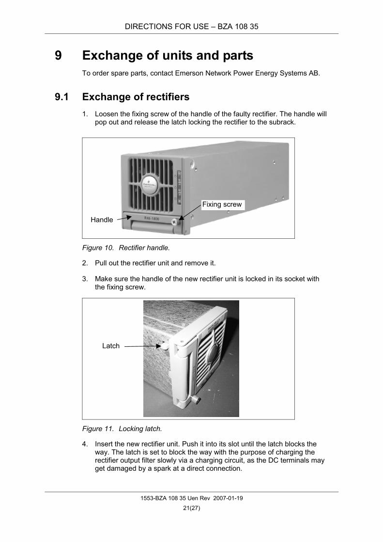
9.1 Exchange of rectifiers 1. Loosen the fixing screw of the handle of the faulty rectifier. The handle will
pop out and release the latch locking the rectifier to the subrack.
Figure 10. Rectifier handle.
2. Pull out the rectifier unit and remove it.
3. Make sure the handle of the new rectifier unit is locked in its socket with the fixing screw.
Figure 11. Locking latch.
4. Insert the new rectifier unit. Push it into its slot until the latch blocks the way. The latch is set to block the way with the purpose of charging the rectifier output filter slowly via a charging circuit, as the DC terminals may get damaged by a spark at a direct connection.
Handle
Fixing screw
Latch

DIRECTIONS FOR USE – BZA 108 35
1553-BZA 108 35 Uen Rev 2007-01-19
22(27)
5. Loosen the fixing screw of the handle, lift the handle, and the latch will with-draw into the rectifier.
6. Continue to push the rectifier into the slot completely.
7. Push the handle into its socket and fasten the fixing screw to lock the rectifier. Now the rectifier is fixed to the slot by the latch. The green LED emits light and the fan will start.
9.2 Rectifier fan replacement If the fan does not work because it is faulty, exchange it for a new one.
1. Remove the rectifier according to item 9.1.
Figure 12. Fan replacement.
2. Loosen the three screws fixing the front cover to the chassis.
3. Lift out the front cover from the chassis and observe the orientation of the fan and its wires.
4. Unplug the power cable of the fan and remove the front cover with the fan.
5. Remove the fan from the front cover by removing its two fixing screws and holders.
6. Replace the fan and fix it to the front cover with the two screws and hold-ers.
7. Plug the fan power cable back into the corresponding socket.
8. Mount the front cover and fix it with the three screws.
9. Reconnect the rectifier according to item 9.1.
Fixing screw and fan holder
Fixing screws
Fan
Front cover
Fan cable plug

DIRECTIONS FOR USE – BZA 108 35
1553-BZA 108 35 Uen Rev 2007-01-19
23(27)
9.3 Exchange of distribution circuit-breaker 1. Open the distribution unit front.
2. Disconnect the distribution cable from the CB.
3. Loosen the CB fixing screw. See Figure 13.
4. Pull the locking device at the bottom of the faulty CB to release it from the DIN-rail.
5. Lift the CB to release it from the connecting fork. See Figure 13.
CB fixing screw
2
3
Figure 13. Releasing a distribution circuit-breaker.
6. Remove the CB according to Figure 14.
connecting fork
Figure 14. Removing a distribution circuit-breaker.

DIRECTIONS FOR USE – BZA 108 35
1553-BZA 108 35 Uen Rev 2007-01-19
24(27)
7. Mount a new CB in the reverse order.
8. Lock the new CB to the DIN-rail and switch it off.
9. Connect the distribution cable to the CB.
10. Mount the front to the distribution unit and fix it with the captive screws.
9.4 Exchange of contactor Note: The system has no backup during this work.
Figure 15. Exchange of contactor.
1. Take off metallic bracelets, rings or similar that may cause short circuits in the equipment. Use insulated tools. Insulate the metal parts close to the contactor with plastic and tape.
2. Open the connector for the signalling cables connected to the contactor.
3. Remove the plastic cover and two rectifiers placed below the contactor.
4. Use an insulated 13 mm U-socket key to loosen the four fixing nuts of the contactor.
5. Hold the contactor and remove the four fixing nuts.
6. Pull the contactor straight down and remove it through the space in the rectifier subrack.
7. Insert the new contactor and fix it with four nuts.
8. Connect the signalling cables to the contactor. If the voltage is OK it should pull up.
9. Fit the plastic cover and two rectifiers below the contactor.

DIRECTIONS FOR USE – BZA 108 35
1553-BZA 108 35 Uen Rev 2007-01-19
25(27)
9.5 Exchange of SCU/ACU Note: An LVD contactor is in it’s OFF- position will reconnect when the
SCU/ACU is removed from a live system.
1. Unlock the control unit by pressing the handle so it pops out and pull out the control unit from the subrack. See Error! Reference source not found..
2. Insert the new control unit into the subrack, push it in completely and lock it by pushing the handle into its socket.
9.6 Exchange of connector board
Figure 16. Connector board.
1. Remove the fixing screw, and then pull out the connector board from the subrack to access the cable connectors. See Error! Reference source not found..
Note: Be careful not to damage the surface mounted components at the back of the board when pulling it out.
2. Disconnect, insulate and mark the signalling cables connected to the ter-minals of the connector board.
3. Exchange the connector board for a new one.
4. Connect the signalling cables to the terminals of the new board.
Note: An LVD contactor is in it’s OFF- position will reconnect when the connec-tor board is reconnected to a live system.
5. Insert the connector board into the subrack, push it in completely and fix it with a screw.
Connectors
Fixing screw

DIRECTIONS FOR USE – BZA 108 35
1553-BZA 108 35 Uen Rev 2007-01-19
26(27)
9.7 Exchange of SCU/ACU supply fuses There are two fuses at the back-plane board of the SCU/ACU. See Figure 17.
If the display of the SCU/ACU is “dead”, the upper fuse (2 A) might have blown. The lower fuse (4 A) protects the supplies of the contactor coils.
Figure 17. Fuses for internal supplies.
2 A for SCU/ACU
4 A for contactors

DIRECTIONS FOR USE – BZA 108 35
1553-BZA 108 35 Uen Rev 2007-01-19
27(27)
10 Abbreviations used in this document AC Alternating Current ACD AC Distribution ACU Advanced Supervision Unit BC Battery Charge BT Battery Test CAN Controller Area Network CB Circuit Breaker CENELEC European Committee for Electrotechnical Standardization DC Direct Current DI Digital Input DSP Digital Signal Processor DU Distribution Unit EEM Emerson EnergyMaster™ ENERGYMASTER is a registered trademark of Emerson Network Power Energy Systems AB EN European Norm ESD ElectroStatic Discharge HVSD High Voltage Switch Down ICU InterConnection Unit LAN Local Area Network LCD Liquid Crystal Display LED Light Emitting Diode LVD Low Voltage Disconnect MFU Multi Function Unit PE Protective Earth PFC Power Factor Controller R Rectifier SCU Standard Supervision Unit SELV Safety Extra Low Voltage SM Supervision Module