Embed Size (px)
Citation preview
Energy Conversion and Management 65 (2013) 155–163
Contents lists available at SciVerse ScienceDirect
Energy Conversion and Management
journal homepage: www.elsevier .com/ locate /enconman
2D heat and mass transfer modeling of methane steam reformingfor hydrogen production in a compact reformer
Meng Ni ⇑Building Energy Research Group, Department of Building and Real Estate, The Hong Kong Polytechnic University, Hung Hom, Kowloon, Hong Kong, China
a r t i c l e i n f o
Article history:Received 19 June 2012Received in revised form 21 July 2012Accepted 21 July 2012Available online 16 October 2012
Keywords:Compact reformerFuel processingPorous mediaHeat and mass transferHydrogen production
0196-8904/$ - see front matter � 2012 Elsevier Ltd. Ahttp://dx.doi.org/10.1016/j.enconman.2012.07.017
⇑ Tel.: +852 2766 4152; fax: +852 2764 5131.E-mail address: [email protected]
a b s t r a c t
Compact reformers (CRs) are promising devices for efficient fuel processing. In CRs, a thin solid plate issandwiched between two catalyst layers to enable efficient heat transfer from combustion duct to thereforming duct for fuel processing. In this study, a 2D heat and mass transfer model is developed to inves-tigate the fundamental transport phenomenon and chemical reaction kinetics in a CR for hydrogen pro-duction by methane steam reforming (MSR). Both MSR reaction and water gas shift reaction (WGSR) areconsidered in the numerical model. Parametric simulations are performed to examine the effects of var-ious structural/operating parameters, such as pore size, permeability, gas velocity, temperature, and rateof heat supply on the reformer performance. It is found that the reaction rates of MSR and WGSR are thehighest at the inlet but decrease significantly along the reformer. Increasing the operating temperatureraises the reaction rates at the inlet but shows very small influence in the downstream. For comparison,increasing the rate of heat supply raises the reaction rates in the downstream due to increased temper-ature. A high gas velocity and permeability facilitates gas transport in the porous structure thus enhancesreaction rates in the downstream of the reformer.
� 2012 Elsevier Ltd. All rights reserved.
1. Introduction
Hydrogen is an ideal energy carrier to support sustainable en-ergy development [1]. Using a fuel cell, hydrogen can be efficientlyconverted into electricity with water as the by-product. To makethe hydrogen energy and fuel cell commercially feasible, it is crit-ical to produce hydrogen efficiently and economically at a largescale.
In the long term, hydrogen can be produced in a clean way bysolar thermochemical water splitting, photocatalytic water split-ting or water electrolysis driven by solar cells/wind turbines[2,3]. However, the present energy efficiencies of both thermo-chemical and photocatalytic hydrogen production methods aretoo low to be economically viable (i.e. efficiency for photocatalytichydrogen production is usually less than 1% [2]). Water electrolytichydrogen production can be a promising technology for large scalehydrogen production but the cost is still high, due to the use ofexpensive catalyst, i.e. Pt. For comparison, steam reforming ofhydrocarbon fuels (i.e. methane) is efficient and can be a feasibleway for hydrogen production for the near term [4]. In general,hydrogen production from methane is based on one of the follow-ing processes: methane steam reforming (MSR), partial oxidation(POX), and autothermal reforming (ATR) [5]. MSR is the most com-
ll rights reserved.
mon method for hydrogen production from methane at a largescale. In MSR reaction (Eq. (1)), methane molecules react withsteam molecules to produce hydrogen and carbon monoxide inthe catalyst layer of reformers. Meanwhile, steam can react withcarbon monoxide to produce additional hydrogen and carbon diox-ide (Eq. (2)), which is called water gas shift reaction (WGSR).
CH4 þH2O$ COþ 3H2 ð1Þ
COþH2O$ CO2 þH2 ð2Þ
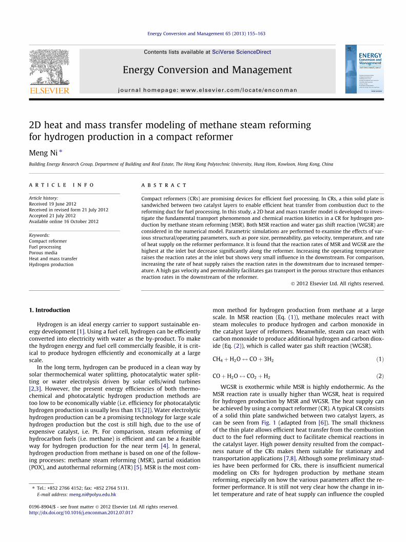
WGSR is exothermic while MSR is highly endothermic. As theMSR reaction rate is usually higher than WGSR, heat is requiredfor hydrogen production by MSR and WGSR. The heat supply canbe achieved by using a compact reformer (CR). A typical CR consistsof a solid thin plate sandwiched between two catalyst layers, ascan be seen from Fig. 1 (adapted from [6]). The small thicknessof the thin plate allows efficient heat transfer from the combustionduct to the fuel reforming duct to facilitate chemical reactions inthe catalyst layer. High power density resulted from the compact-ness nature of the CRs makes them suitable for stationary andtransportation applications [7,8]. Although some preliminary stud-ies have been performed for CRs, there is insufficient numericalmodeling on CRs for hydrogen production by methane steamreforming, especially on how the various parameters affect the re-former performance. It is still not very clear how the change in in-let temperature and rate of heat supply can influence the coupled
Nomenclature
Bg permeability of electrode (m2)cp heat capacity (kJ kg�1 K�1)Deff
i effective diffusion coefficient of species i (m2 s�1)Di,k Knudsen diffusion coefficient of i (m2 s�1)Di,j binary diffusion coefficient of i and j (m2 s�1)F Faraday constant (C mol�1)k thermal conductivity (W m�1 K�1)L thickness of electrolyte (m)Mi molecular weight of species i (kg mol�1)P operating pressure (atm)R universal gas constant (kJ mol�1 K�1)RMSR rate of methane steam reforming reaction (mol m�3 s�1)RWGSR rate of water gas shift reaction (mol m�3 s�1)rp mean pore radius of electrode (m)Sm source term in continuity equation (kg m�3 s�1)
Sx, Sy source terms in momentum equations (kg m�2 s�2)ST source term in energy equation (W m�3)Ssp source term in species equations (kg m�3 s�1)DS entropy change (kJ mol�1 K�1)T operating temperature (K)U velocity in x direction (m s�1)U0 gas velocity at the inlet (m s�1)V velocity in y direction (m s�1)Xi molar fraction of species i (–)Yi mass fraction of species i (–)l viscosity (kg m�1 s�1)e electrode porosity (–)n electrode tortuosity (–)XD dimensionless diffusion collision integral (–)q density of the gas mixture (kg m�3)
156 M. Ni / Energy Conversion and Management 65 (2013) 155–163
transport and reaction kinetics in the reformer, which are impor-tant for optimization of the reformer operation conditions. In addi-tion, the study in the literature considers pre-reformed methanegas consisting of CH4, H2O, CO, CO2, and H2 gas mixture at the inlet[6]. While it may be more appropriate to use CH4/H2O mixture asthe feeding gas to the reformer.
In this paper, 2D numerical model is developed to simulate theperformance of a CR for methane reforming. Different from theprevious studies using pre-reformed gas mixtures at the inlet,the present study uses a CH4/H2O mixture at the reformer inlet.In real application, the steam to carbon ratio (SCR) is an importantparameter as carbon deposition can occur at a low (i.e. less than 1)SCR [9]. As the present study do not consider the carbon depositionbehavior in the reformer, a constant SCR of 2.0 is adopted. The ef-fects of the reformer structural/operating parameters on the cou-pled transport and reaction phenomena are investigated anddiscussed in detail.
2. Model development
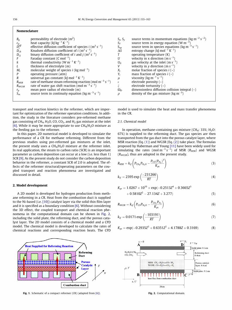
A 2D model is developed for hydrogen production from meth-ane reforming in a CR. Heat from the combustion duct is suppliedto the Ni-based (i.e. [10]) catalyst layer via the solid thin film layerand it is specified as a boundary condition [6]. Without consideringthe 3D effect, the coupled transport and chemical reaction phe-nomena in the computational domain can be shown in Fig. 2,including the solid plate, the reforming duct, and the porous cata-lyst layer. The 2D model consists of a chemical model and a CFDmodel. The chemical model is developed to calculate the rates ofchemical reactions and corresponding reaction heats. The CFD
Fig. 1. Schematic of a compact reformer (CR) (adapted from [6]).
model is used to simulate the heat and mass transfer phenomenain the CR.
2.1. Chemical model
In operation, methane-containing gas mixture (CH4: 33%; H2O:67%) is supplied to the reforming duct. The gas species are thentransported from the gas duct into the porous catalyst layer, whereMSR reaction (Eq. (1)) and WGSR (Eq. (2)) take place. The formulasproposed by Haberman and Young [11] have been widely used forsimulating the rates (mol m�3 s�1) of MSR (RMSR) and WGSR(RWGSR), thus are adopted in the present study.
RMSR ¼ krf PCH4 PH2O �PCOðPH2 Þ
3
Kps
!ð3Þ
krf ¼ 2395 exp�231266
RT
� �ð4Þ
Kpr ¼ 1:0267� 1010 � expð�0:2513Z4 þ 0:3665Z3
þ 0:5810Z2 � 27:134Z þ 3:277Þ ð5Þ
RWGSR ¼ ksf PCOPH2O �PCO2 PH2
Kps
� �ð6Þ
ksf ¼ 0:0171 exp�103191
RT
� �ð7Þ
Kps ¼ expð�0:2935Z3 þ 0:6351Z2 þ 4:1788Z þ 0:3169Þ ð8Þ
Fig. 2. Computational domain.
M. Ni / Energy Conversion and Management 65 (2013) 155–163 157
Z ¼ 1000TðKÞ � 1 ð9Þ
where T is the temperature (K), R is the universal gas constant(8.3145 J mol�1K�1). P is partial pressures of gas species (Pa).
The amount of heat generation from WGSR and heat consump-tion by MSR reaction can be calculated using corresponding enthal-py changes [12]. Assuming linear dependence on operatingtemperature between 600 K and 1200 K, the reaction heats(J mol�1) for MSR reaction and WGSR can be calculated as [13].
HMSR ¼ �ð206205:5þ 19:5175TÞ ð10Þ
HWGSR ¼ 45063� 10:28T ð11Þ
Table 1Parameters used in calculating the effective diffusion coefficients [16].
CO CO2 H2 O2 CH4 N2 H2O
ri 3.69 3.941 2.827 3.467 3.758 3.798 2.641e /k 91.7 195.2 59.7 106.7 148.6 71.4 809.1
2.2. Computational fluid dynamics (CFD) model
Assuming local thermal equilibrium in the porous catalyst layer,the governing equations for mass conservation, momentum con-servation, and energy conservation for the whole computationaldomain are summarized as follows [14]:
@ðqUÞ@x
þ @ðqVÞ@y
¼ 0 ð12Þ
@ðqUUÞ@x
þ @ðqVUÞ@y
¼ � @P@xþ @
@xl @U@x
� �þ @
@yl @U@y
� �þ Sx ð13Þ
@ðqUVÞ@x
þ @ðqVVÞ@y
¼ � @P@yþ @
@xl @V@x
� �þ @
@yl @V@y
� �þ Sy ð14Þ
@ðqcPUTÞ@x
þ @ðqcPVTÞ@y
¼ @
@xk@T@x
� �þ @
@yk@T@y
� �þ ST ð15Þ
@ðqUYiÞ@x
þ @ðqVYiÞ@y
¼ @
@xqDeff
i;m
@Yi
@x
� �þ @
@yqDeff
i;m
@Yi
@y
� �þ Ssp ð16Þ
where U and V are the velocity components in x and y directionsrespectively; q and l are the density and viscosity of the gas mix-ture; k is the thermal conductivity; cp is the heat capacity; Deff
i;m isthe effective diffusion coefficient of species i in gas mixture. Bothq and l depend on the local composition and temperature of thegas mixture, which is treated as an ideal gas. In the porous catalystlayer, effective heat conductivity and heat capacity are used and canbe calculated as [15],
k ¼ ekf þ ð1� eÞks ð17Þ
cp ¼ ecp;f þ ð1� eÞcp;s ð18Þ
where e is the porosity of the porous catalyst layer; kf and ks are theheat conductivity (W m�1 K�1) of the fluid and solid, respectively;cp,f and cp,s are the heat capacity (J kg�1 K�1) of the fluid and solid,respectively.
The mass fraction of species i (Yi) can be related to the molarfraction (Xi) and molecular weight (Mi) of species i,
Yi ¼ XiMiPN
i¼1XiMi
!ð19Þ
The density of the gas mixture q can be calculated as,
q ¼ 1PNi¼1Yi=qi
ð20Þ
where qi is the density of gas species i.The viscosity of the gas mixture (l) can be obtained by Wilke’s
method [16].
l ¼Xn
i¼1
yiliPnj¼1yjuij
ð21Þ
The value of uij can be determined by Herning and Zipperer approx-imation as [16]
uij ¼
ffiffiffiffiffiffiMj
Mi
s¼ u�1
ji ð22Þ
The effective diffusion coefficient of species i (Deffi;m) can be deter-
mined as [17]:
1
Deffi;m
¼ ne
Pj–i
Xj
Dij
1� Xiþ 3
2rp
ffiffiffiffiffiffiffiffiffipMi
8RT
r0@
1A ð23Þ
Dij ¼0:0026T1:5
pffiffiffiffiffiffiffiffiffiffiffi2MiMj
MjþMi
qriþrj
2
� �2XD
ð24Þ
XD ¼1:06036kbTei;j
� �0:1561 þ0:193
exp 0:47635 kbTei;j
� �� �
þ 1:03587
exp 1:52996 kbTei;j
� �� �þ 1:76474
3:89411 kbTei;j
� � ð25Þ
where n/e is the ratio of tortuosity to porosity of porous catalystlayer; and rp is the radius of pores. Dij is the binary diffusion coeffi-cient of species i and j. r is the mean characteristic length of speciesand XD is a dimensionless diffusion collision. kb is the Boltzmann’sconstant ([1.38066 � 10�23(J K�1)). The values of ri and ei,j used inthe present study are summarized in Table 1 [16].
The Darcy’s law (Eqs. (26) and (27)) is used as source terms inmomentum equations (Eqs. (13) and (14)), so that the momentumequations are applicable for both the gas channels and the porouscatalyst layers. A suitable permeability (Bg) is assigned to the por-ous catalyst layer and an infinitely large permeability is used forthe reforming duct. The source term in energy equation (Eq.(15)) represents reaction heat from the chemical reactions can becalculated by Eq. (28). The source term in species equation (Eq.(16)) represents the mass consumption/generation by MSR andWGSR reactions. Detailed descriptions of the source terms can befound in the previous publications [17].
Sx ¼ �lUBg
ð26Þ
Sy ¼ �lVBg
ð27Þ
ST ¼ RMSRHMSR þ RWGSRHWGSR ð28Þ
2.3. Numerical scheme
The governing equations in the CFD model are solved with thefinite volume method (FVM) [14]. As a real reformer stack consistsof many identical single compact reformers, it is assumed that heatis supplied from the combustion channel (Fig. 1) and there is noheat transfer between compact reformers through the upper
i
158 M. Ni / Energy Conversion and Management 65 (2013) 155–163
boundary (y = yM). Therefore, adiabatic condition is applied to theupper boundary (y = yM) while a constant heat flux is specified atthe lower boundary (y = 0). The convection terms and diffusionterms are treated with the upwind difference scheme and centraldifference scheme, respectively. The velocity and pressure arelinked with the SIMPLEC algorithm. The TDMA based alternativeiteration scheme is employed to solve the discretized equations.The rates of chemical reactions and corresponding reaction heatsobtained from the chemical model are used as source terms inthe CFD model. Computation is repeated until convergence isachieved. The in-house code is written in FORTRAN.
3. Results and discussions
The chemical model and CFD model have been validated in theprevious publications by comparing the modeling results with datafrom the literature [17]. The dimensions and typical simulationparameters are summarized in Table 2. The following sections fo-cus on parametric simulations to analyze the effects of operatingand structural parameters on the coupled transport and reactionkinetics in CR. The effects of SCR and the catalyst nature on CR per-formance are not included but will be considered in future works.
3.1. Coupled transport and reaction in a compact reformer forhydrogen production
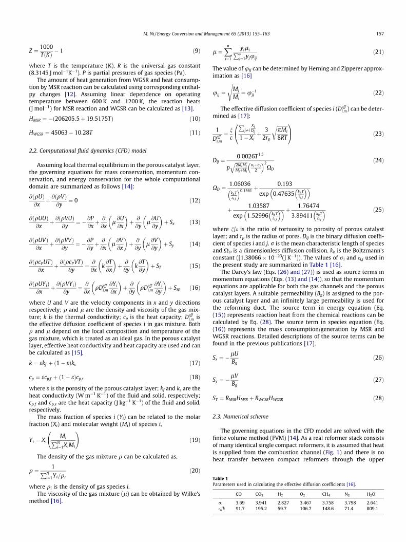
Fig. 3 shows the distributions of MSR reaction rates, WGSRrates, temperature, velocity, gas composition (CH4 and H2 as exam-ples) in the compact reformer at an inlet temperature of 1073 K, in-let gas velocity of 3 m s�1, and heat supply rate (from the solidplate) of 1 kW m�2. The reaction rates for MSR and WGSR are thehighest (25.4 and 14 mol m�3 s�1 respectively) at the inlet and de-crease considerably in the downstream of the reformer (Fig. 3a andb). The calculated reaction rates are well consistent with the exper-imental data from Refs. [18,19]. The high reaction rates near the in-let are mainly caused by high concentration of the reactants,especially the concentration of CH4 (for MSR) and H2O (for WGSR).In addition, the temperature is the highest at the inlet (Fig. 3c). Thecalculated reaction rates for MSR are in general higher than thosefor WGSR (Fig. 3a and b). As MSR reaction is endothermic whileWGSR is exothermic, the temperature decreases from 1073 K atthe inlet to about 1007 K at the outlet (Fig. 3c). Fig. 3d shows thevelocity contours profile (U/U0) along the main flow stream. Simi-lar to forced duct flow, velocity ratio (U/U0) increases from zeronear the wall to the highest in the core zone (Fig. 3d). The velocityin the catalyst layer is negligible due to small permeation(10�10 m2) used in the simulation. The molar fraction of CH4 isfound to decrease along the CR flow channel (Fig. 3e), due toMSR reaction. A locally low molar fraction of CH4 is also observednear the inlet in the catalyst layer (Fig. 3e). This is caused by high
Table 2Parameters used in simulation.
Parameter Value
Operating temperature, T (K) 1173Operating pressure, P (bar) 1.0Porosity of the porous catalyst layer, e 0.4Tortuosity of the porous catalyst layer, n 3.0Permeability of the porous catalyst layer, Bg (m2) 2 � 10�10
Average pore radius, rp (lm) 1.0Thickness of the porous catalyst layer (cm) 0.4Length of the compact reformer (cm) 20Thickness of solid plate (cm) 0.1Inlet velocity at the reforming duct, U0 (m s�1) 3.0Height of the reforming duct (cm) 0.4
reaction rates of MSR and slow transport of CH4 from the gas chan-nel into the catalyst layer. For comparison, the molar fraction of H2
increases along the CR gas flow stream (Fig. 3f). High molar fractionof H2 is observed in the zones near the inlet and the outlet. Thehigh molar fraction of H2 near the inlet (in the catalyst layer) ismainly caused by the locally high reaction rates of MSR and WGSR.The high molar fraction of H2 near the outlet is caused by slow dif-fusion and thus accumulation of H2 in the catalyst layer.
3.2. Effect of inlet temperature
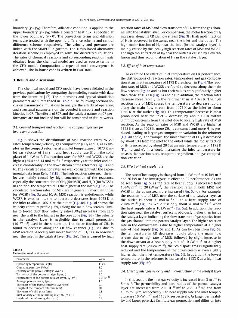
To examine the effect of inlet temperature on CR performance,the distributions of reaction rates, temperature and gas composi-tion at an inlet temperature of 1173 K are shown in Fig. 4. The reac-tion rates of MSR and WGSR are found to decrease along the mainflow stream (Fig. 4a and b), but their values are significantly higherthan those at 1073 K (Fig. 3a and b). In addition, the reaction ratesdecrease more rapidly in the reformer than at 1073 K. The highreaction rate of MSR causes the temperature to decrease rapidlyalong the main flow stream from 1173 K at the inlet to about1040 K at the outlet (Fig. 4c). This temperature decrease is mostpronounced near the inlet – decrease by about 100 K within3 mm downstream from the inlet due to locally high rate of MSRreaction. As the reaction rates of MSR and WGSR are higher at1173 K than at 1073 K, more CH4 is consumed and more H2 is pro-duced, leading to larger gas composition variation in the reformer(Fig. 4d and e). For example, the molar fraction of CH4 is decreasedby about 13% from the inlet to the outlet while the molar fractionof H2 is increased by about 20% at an inlet temperature of 1173 K(Fig. 4d and e). In a word, increasing the inlet temperature in-creases the reaction rates, temperature gradient, and gas composi-tion variation.
3.3. Effect of heat supply rate
The rate of heat supply is changed from 1 kW m�2 to 10 kW m�2
and 20 kW m�2 to investigate its effect on CR performance. As canbe seen from Fig. 5, as the rate of heat supply is increased from10 kW m�2 to 20 kW m�2, the reaction rates of both MSR andWGSR in the downstream are increased (Fig. 5a–d). For example,the reaction rate of MSR near the surface of the catalyst layer atthe outlet is about 40 mol m�3 s�1 at a heat supply rate of20 kW m�2 (Fig. 5b), while it is only about 20 mol m�3 s�1 whenthe heat supply rate is 10 kW m�2 (Fig. 5a). In addition, the reac-tion rates near the catalyst surface is obviously higher than insidethe catalyst layer, indicating the slow transport of gas species fromthe gas channel into the porous catalyst layer. The higher reactionrate in the downstream is due to higher temperature at a higherrate of heat supply (Fig. 5e and f). As can be seen from Fig. 5e,the temperature in CR decreases rapidly along the main flowstream due to high rate of MSR, followed by slight increase inthe downstream at a heat supply rate of 10 kW m�2. At a higherheat supply rate (20 kW m�2), the ‘‘cold spot’’ area is significantlyreduced and the temperature in the downstream is even slightlyhigher than the inlet temperature (Fig. 5f). In addition, the lowesttemperature in the reformer is increased to 1133 K at a high heatsupply rate (Fig. 5f).
3.4. Effect of inlet gas velocity and microstructure of the catalyst layer
In this section, the inlet gas velocity is increased from 3 m s�1 to5 m s�1. The permeability and pore radius of the porous catalystlayer are increased from 2 � 10�10 m2 to 2 � 10�8 m2 and from1 lm to 5 lm, respectively. The heat supply rate and inlet temper-ature are 10 kW m�2 and 1173 K, respectively. As larger permeabil-ity and larger pore size facilitate gas permeation and diffusion into
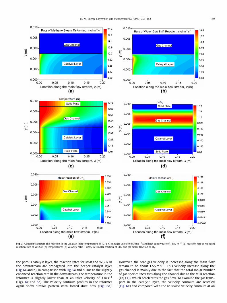
Fig. 3. Coupled transport and reaction in the CR at an inlet temperature of 1073 K, inlet gas velocity of 3 m s�1; and heat supply rate of 1 kW m�2: (a) reaction rate of MSR; (b)reaction rate of WGSR; (c) temperature; (d) velocity ratio – U/U0; (e) molar fraction of CH4 and (f) molar fraction of H2.
M. Ni / Energy Conversion and Management 65 (2013) 155–163 159
the porous catalyst layer, the reaction rates for MSR and WGSR inthe downstream are propagated into the deeper catalyst layer(Fig. 6a and b), in comparison with Fig. 5a and c. Due to the slightlyenhanced reaction rate in the downstream, the temperature in thereformer is slightly lower than at an inlet velocity of 3 m s�1
(Figs. 6c and 5e). The velocity contours profiles in the reformeragain show similar pattern with forced duct flow (Fig. 6d).
However, the core gas velocity is increased along the main flowstream to be about 1.55 m s�1. This velocity increase along thegas channel is mainly due to the fact that the total molar numberof gas species increases along the channel due to the MSR reaction(Eq. (1)), which accelerates the gas flow. To examine the gas trans-port in the catalyst layer, the velocity contours are rescaled(Fig. 6e) and compared with the re-scaled velocity contours at an
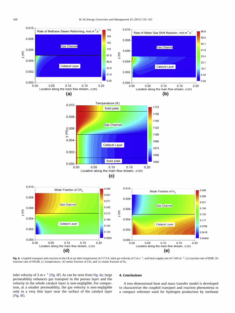
Fig. 4. Coupled transport and reaction in the CR at an inlet temperature of 1173 K, inlet gas velocity of 3 m s�1; and heat supply rate of 1 kW m�2: (a) reaction rate of MSR; (b)reaction rate of WGSR, (c) temperature; (d) molar fraction of CH4 and (e) molar fraction of H2.
160 M. Ni / Energy Conversion and Management 65 (2013) 155–163
inlet velocity of 3 m s�1 (Fig. 6f). As can be seen from Fig. 6e, largepermeability enhances gas transport in the porous layer and thevelocity in the whole catalyst layer is non-negligible. For compar-ison, at a smaller permeability, the gas velocity is non-negligibleonly in a very thin layer near the surface of the catalyst layer(Fig. 6f).
4. Conclusions
A two-dimensional heat and mass transfer model is developedto characterize the coupled transport and reaction phenomena ina compact reformer used for hydrogen production by methane
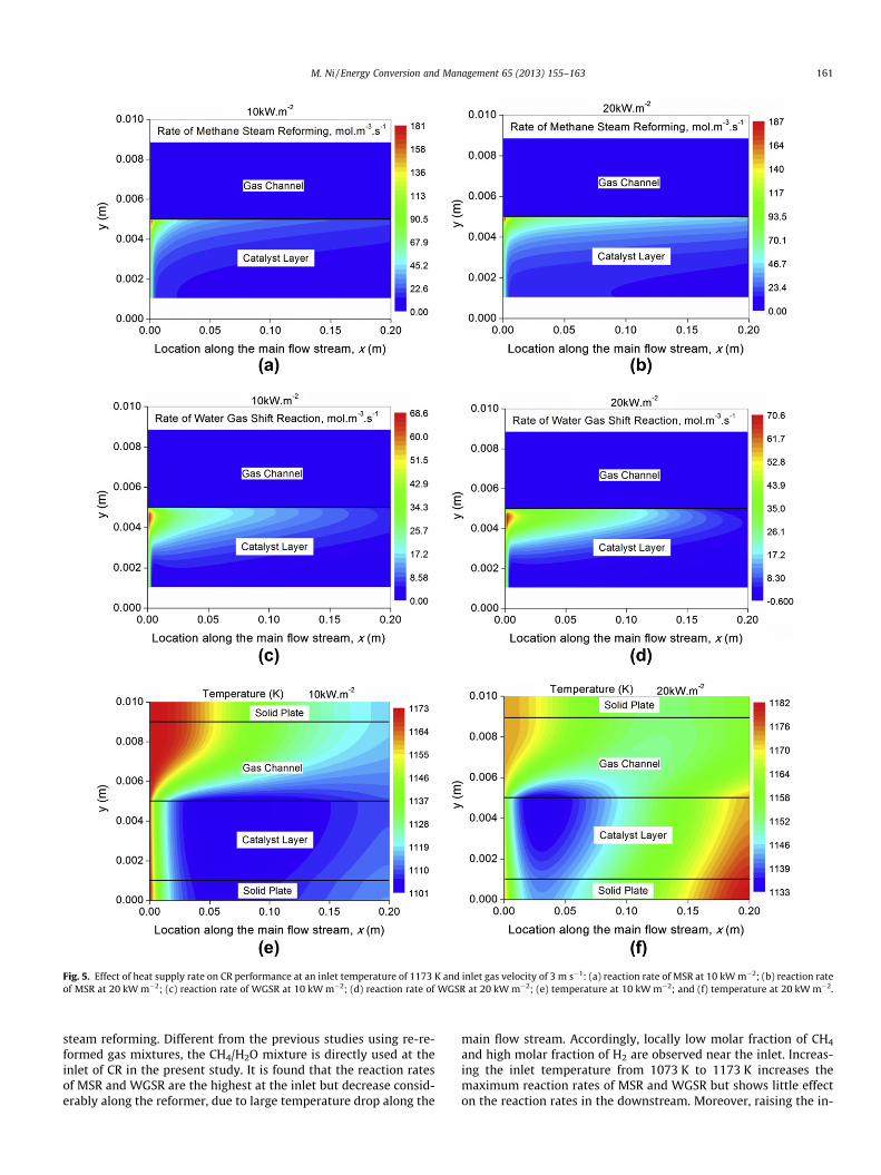
Fig. 5. Effect of heat supply rate on CR performance at an inlet temperature of 1173 K and inlet gas velocity of 3 m s�1: (a) reaction rate of MSR at 10 kW m�2; (b) reaction rateof MSR at 20 kW m�2; (c) reaction rate of WGSR at 10 kW m�2; (d) reaction rate of WGSR at 20 kW m�2; (e) temperature at 10 kW m�2; and (f) temperature at 20 kW m�2.
M. Ni / Energy Conversion and Management 65 (2013) 155–163 161
steam reforming. Different from the previous studies using re-re-formed gas mixtures, the CH4/H2O mixture is directly used at theinlet of CR in the present study. It is found that the reaction ratesof MSR and WGSR are the highest at the inlet but decrease consid-erably along the reformer, due to large temperature drop along the
main flow stream. Accordingly, locally low molar fraction of CH4
and high molar fraction of H2 are observed near the inlet. Increas-ing the inlet temperature from 1073 K to 1173 K increases themaximum reaction rates of MSR and WGSR but shows little effecton the reaction rates in the downstream. Moreover, raising the in-
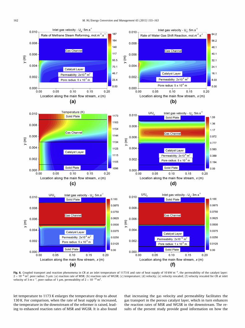
Fig. 6. Coupled transport and reaction phenomena in CR at an inlet temperature of 1173 K and rate of heat supply of 10 kW m�2, the permeability of the catalyst layer:2 � 10�8 m2, pore radius: 5 lm: (a) reaction rate of MSR; (b) reaction rate of WGSR; (c) temperature; (d) velocity; (e) velocity rescaled; (f) velocity rescaled for CR at inletvelocity of 3 m s�1, pore radius of 1 lm, permeability of 2 � 10�10 m2.
162 M. Ni / Energy Conversion and Management 65 (2013) 155–163
let temperature to 1173 K enlarges the temperature drop to about130 K. For comparison, when the rate of heat supply is increased,the temperature in the downstream of the reformer is raised, lead-ing to enhanced reaction rates of MSR and WGSR. It is also found
that increasing the gas velocity and permeability facilitates thegas transport in the porous catalyst layer, which in turn enhancesthe reaction rates of MSR and WGSR in the downstream. The re-sults of the present study provide good information on how the
M. Ni / Energy Conversion and Management 65 (2013) 155–163 163
operating and structural parameters affect the coupled transportand reaction kinetics in CR, which are important for CR stackoptimization.
Acknowledgement
This research was supported by a grant (Project Number: PolyU5238/11E) from Research Grant Council (RGC) of Hong Kong.
References
[1] Granovskii M, Dincer I, Rosen MA, Pioro I. Performance assessment of acombined system to link a supercritical water-cooled nuclear reactor and athermaochemical water splitting cycle for hydrogen production. EnergyConvers Manage 2008;49:1873–81.
[2] Ni M, Leung MKH, Leung DYC, Sumathy K. A review and recent developmentsin photocatalytic water-splitting using TiO2 for hydrogen production. RenewSustain Energy Rev 2007;11:401–25.
[3] Rivera-Tinoco R, Mansilla C, Bouallou C. Competitiveness of hydrogenproduction by high temperature electrolysis: impact of the heat source andidentification of key parameters to achieve low production cost. EnergyConvers Manage 2010;51:2623–34.
[4] Yoon SJ, Choi Y, Lee J. Hydrogen production from biomass tar by catalyticsteam reforming. Energy Convers Manage 2010;51:42–7.
[5] Xuan J, Leung MKH, Leung DYC, Ni M. Integrating chemical kinetics with CFDmodelling for autothermal reforming of biogas. Int J Hydrogen Energy2009;34:9076–86.
[6] Yuan JL, Lv XR, Sunden B, Yue DT. Analysis of parameter effects on transportphenomena in conjunction with chemical reactions in ducts relevant formethane reformers. Int J Hydrogen Energy 2007;32:3887–98.
[7] Zanfir M, Gavriilidis A. Catalytic combustion assisted methane steamreforming in a catalytic plate reactor. Chem Eng Sci 2003;58:3947–60.
[8] Yuan JL, Ren F, Sunden B. Analysis of chemical-reaction-coupled mass and heattransport phenomena in a methane reformer duct for PEMFCs. Int J Heat MassTransfer 2007;50:687–701.
[9] Lee TS, Chung JN, Chen YC. Design and optimization of a combined fuelreforming and solid oxide fuel cell system with anode off-gas recycling. EnergyConvers Manage 2011;52:3214–26.
[10] Jiang T, Zhang Q, Wang TJ, Zhang Q, Ma LL. High yield of pentane production byaqueous-phase reforming of xylitol over Ni/HZSM-5 and Ni/MCM22 catalysts.Energy Convers Manage 2012;59:58–65.
[11] Haberman BA, Young JB. Three-dimensional simulation of chemically reactinggas flows in the porous support structure of an integrated-planar solid oxidefuel cell. Int J Heat Mass Transfer 2004;47:3617–29.
[12] Chase MW. NIST-JANAF thermochemical tables. 4th edition. AmericanChemical Society, American Institute of Physics for the National Institute ofStandards and Technology; 1998.
[13] Ni M. 2D thermal modeling of a solid oxide electrolyzer cell (SOEC) for syngasproduction by H2O/CO2 co-electrolysis. Int J Hydrogen Energy2012;37:6389–99.
[14] Wang CY. Fundamental models for fuel cell engineering. Chem Rev2004;104:4727–65.
[15] Ni M. Thermo-electrochemical modelling of ammonia-fueled solid oxide fuelcells considering ammonia thermal decomposition in the anode. Int JHydrogen Energy 2011;36:2027–36.
[16] Reid RC, Prausnitz JM, Poling BE. The properties of gases & liquids. 4th ed. NewYork: McGraw-Hill Book Company; 1987.
[17] Ni M. Modeling of SOFC running on partially pre-reformed gas mixture. Int JHydrogen Energy 2012;37:1731–45.
[18] Lehnert W, Meusinger J, Thom F. Modeling of gas transport phenomena inSOFC anodes. J Power Sources 2000;87:57–63.
[19] Drescher I, Lehnert W, Meusinger J. Structural properties of SOFC anodes andreactivity. Electrochim Acta 1998;43:3059–68.