Embed Size (px)
Citation preview
2CKA001473B8903 │ 21.07.2017
KNX Technical Reference Manual
Busch-ControlTouch®
Busch-ControlTouch®
6136/APP-500
Table of contents
KNX Technical Reference Manual 2CKA001473B8903 │2
Table of contents
1 Notes on the instruction manual ................................................................................................................. 6
2 Safety ......................................................................................................................................................... 7 2.1 Information and symbols used ........................................................................................................ 7 2.2 Intended use ................................................................................................................................... 8 2.3 Improper use ................................................................................................................................... 8 2.4 Target group / Qualifications of personnel ...................................................................................... 8
2.4.1 Installation, commissioning and maintenance ................................................................................. 8 2.5 Safety instructions ........................................................................................................................... 9
3 Information on protection of the environment ........................................................................................... 10 3.1 Environment .................................................................................................................................. 10
4 Setup and function ................................................................................................................................... 11 4.1 Device overview ............................................................................................................................ 11 4.2 Scope of supply ............................................................................................................................ 12 4.3 Overview of types ......................................................................................................................... 12 4.4 Functions ...................................................................................................................................... 13
4.4.1 Function overview...........................................................................................................................13 4.4.2 Description of functions ..................................................................................................................14
5 Technical data .......................................................................................................................................... 15 5.1 Technical data ............................................................................................................................... 15 5.2 Dimensional drawings ................................................................................................................... 16
6 Connection, installation / mounting ........................................................................................................... 17 6.1 Requirements for the electrician.................................................................................................... 17 6.2 Mounting ....................................................................................................................................... 18 6.3 Electrical connection ..................................................................................................................... 19
7 Operation ................................................................................................................................................. 20 7.1 Extended operation ....................................................................................................................... 20
7.1.1 RESET OPTIONS ..........................................................................................................................20 7.1.2 Operating statuses .........................................................................................................................21 7.1.3 Operation of system via the app ....................................................................................................21
8 Commissioning ......................................................................................................................................... 22 8.1 Brief instructions for typical commissioning ................................................................................... 22
8.1.1.1 Implementation by fitter / expert .....................................................................22 8.1.1.2 Implementation by end user (Continuation of previous view) ........................24
8.2 Preparatory steps .......................................................................................................................... 26 8.3 Explanation of commissioning procedure ...................................................................................... 26
8.3.1 Overview of configuration ...............................................................................................................27 8.4 Login / registration of a Busch-ControlTouch® .............................................................................. 28
8.4.1 First login of the Busch-ControlTouch® at myABB Living Space® without an available access.............................................................................................................................................29 8.4.1.1 Registration and login .....................................................................................29
Table of contents
KNX Technical Reference Manual 2CKA001473B8903 │3
8.4.1.2 Registering and setting up the Busch-ControlTouch® via myABB Living Space® ............................................................................................................30
8.4.2 Initial commissioning of device (direct access) ..............................................................................32 8.4.3 Sending an invitation to the customer ............................................................................................34 8.4.4 Login of new Busch-ControlTouch® at myABB Living Space® with existing access .....................35
8.5 Creating a project - System configuration ..................................................................................... 36 8.5.1 General information ........................................................................................................................36 8.5.2 Creating a project ...........................................................................................................................37
8.5.2.1 Opening the configuration page .....................................................................37 8.5.3 Group addresses ............................................................................................................................40 8.5.4 Cameras .........................................................................................................................................44 8.5.5 Commands .....................................................................................................................................46 8.5.6 Data logger .....................................................................................................................................47 8.5.7 Presence detection .........................................................................................................................49 8.5.8 Triggers...........................................................................................................................................50 8.5.9 Scripts .............................................................................................................................................52
8.5.9.1 Creation of scripts ...........................................................................................54 8.5.10 Assigning a project to a device ......................................................................................................65 8.5.11 Copy project ...................................................................................................................................65 8.5.12 Delete project .................................................................................................................................65 8.5.13 Project backup ................................................................................................................................65 8.5.14 Restoring a backup project .............................................................................................................66 8.5.15 Exporting a project (export function) ..............................................................................................66 8.5.16 Importing a project (import function) ..............................................................................................66
8.6 Creating a profile ........................................................................................................................... 67 8.6.1.1 Opening the configuration page .....................................................................67 8.6.1.2 Call-up of standard profile ..............................................................................69 8.6.1.3 Create new profile ..........................................................................................71
8.6.2 Copy profile ....................................................................................................................................71 8.6.3 Delete profile ..................................................................................................................................71 8.6.4 Profile backup .................................................................................................................................71 8.6.5 Restoring a backup profile ..............................................................................................................72 8.6.6 Exporting a profile (export function) ...............................................................................................72 8.6.7 Importing a profile (import function) ...............................................................................................72 8.6.8 Blocking a profile (blocking function) ..............................................................................................72 8.6.9 Creation of pages ...........................................................................................................................73
8.6.9.1 Call-up of standard page ................................................................................73 8.6.9.2 Opening the configuration page .....................................................................73 8.6.9.3 Create a new page .........................................................................................76
8.6.10 Listing of profile(page) elements (actions) .....................................................................................77 8.6.10.1 RTC mode selection .......................................................................................77 8.6.10.2 Command sender ...........................................................................................78 8.6.10.3 Display light intensity ......................................................................................79 8.6.10.4 Data Logger ....................................................................................................80 8.6.10.5 Date / time ......................................................................................................81 8.6.10.6 Dimmer ...........................................................................................................82 8.6.10.7 Goto account ..................................................................................................83 8.6.10.8 Goto menu ......................................................................................................84 8.6.10.9 Group header .................................................................................................85 8.6.10.10 Blind ................................................................................................................86 8.6.10.11 Camera ...........................................................................................................87 8.6.10.12 Empty space ...................................................................................................88
Table of contents
KNX Technical Reference Manual 2CKA001473B8903 │4
8.6.10.13 Display atm. pressure .....................................................................................88 8.6.10.14 Display atmospheric humidity .........................................................................89 8.6.10.15 RGB control ....................................................................................................90 8.6.10.16 Switch .............................................................................................................91 8.6.10.17 Page link .........................................................................................................92 8.6.10.18 Static text ........................................................................................................92 8.6.10.19 Scene ..............................................................................................................93 8.6.10.20 Push button row ..............................................................................................94 8.6.10.21 Display temperature .......................................................................................96 8.6.10.22 Change temperature.......................................................................................97 8.6.10.23 UPnP slider .....................................................................................................99 8.6.10.24 Variable text ................................................................................................. 100 8.6.10.25 Web page .................................................................................................... 101 8.6.10.26 Display value ............................................................................................... 102 8.6.10.27 Value controller ............................................................................................ 103 8.6.10.28 Value transmitter ......................................................................................... 105 8.6.10.29 Value push button ........................................................................................ 106 8.6.10.30 Display windspeed ....................................................................................... 107
8.6.11 Deleting pages ............................................................................................................................. 107 8.6.12 Copying the page element .......................................................................................................... 108 8.6.13 Copy pages ................................................................................................................................. 108 8.6.14 Deleting pages ............................................................................................................................. 108 8.6.15 Alarms .......................................................................................................................................... 109
8.6.15.1 Opening the configuration page .................................................................. 109 8.6.15.2 Overview of alarms ...................................................................................... 111 8.6.15.3 Create and add alarms ................................................................................ 111 8.6.15.4 Adjust alarm ................................................................................................. 112 8.6.15.5 Delete alarm ................................................................................................ 112
8.7 Additional settings for the device (configuration page) ................................................................ 112 8.7.1.1 Opening the configuration page .................................................................. 113
8.7.2 App settings ................................................................................................................................. 114 8.7.3 Local users .................................................................................................................................. 115
8.7.3.1 Overview of users ........................................................................................ 115 8.7.3.2 Create and add users .................................................................................. 115 8.7.3.3 Adjust users ................................................................................................. 116 8.7.3.4 Delete users ................................................................................................ 116
8.7.4 Access rights (roles) .................................................................................................................... 116 8.7.4.1 Overview of roles ......................................................................................... 116 8.7.4.2 Create and add roles ................................................................................... 117 8.7.4.3 Adjust roles .................................................................................................. 117 8.7.4.4 Delete roles ................................................................................................. 118
8.7.5 Sending an invitation to the customer ......................................................................................... 118 8.7.6 Logging out a specialist's account Confirming the log-in of a specialist ..................................... 119 8.7.7 Creating a widget function for iOS .............................................................................................. 119
8.8 Importing the configuration into the Busch-ControlTouch® .......................................................... 120 8.9 Settings in the device (direct access) .......................................................................................... 121
8.9.1 Global settings ............................................................................................................................. 122 8.9.2 Status specifications .................................................................................................................... 124 8.9.3 Optional creation of scenes ......................................................................................................... 125 8.9.4 Optional setting of time programs (timer) .................................................................................... 127 8.9.5 Proxy settings – Internet connection (Port allocation) ................................................................ 129
Table of contents
KNX Technical Reference Manual 2CKA001473B8903 │5
8.9.6 Integration of UPnP devices ........................................................................................................ 130 8.9.7 Adjustment of KNX settings......................................................................................................... 131 8.9.8 User protocols ............................................................................................................................. 132 8.9.9 Change password........................................................................................................................ 132 8.9.10 Granting authorization ................................................................................................................. 132 8.9.11 Configuration of Philips Hue ........................................................................................................ 133 8.9.12 Display of available scripts .......................................................................................................... 134 8.9.13 Display of existing alarm messages ............................................................................................ 134 8.9.14 Restart the device........................................................................................................................ 134 8.9.15 Reset to factory settings .............................................................................................................. 135 8.9.16 Activating remote access via myABB Living Space® .................................................................. 135 8.9.17 Presence simulation – self-learning function .............................................................................. 136
8.10 Installation and setting of the app ............................................................................................... 137 8.10.1 Installation process ...................................................................................................................... 137 8.10.2 Start screen after installation ....................................................................................................... 137 8.10.3 Settings ........................................................................................................................................ 137 8.10.4 Default Settings ........................................................................................................................... 141 8.10.5 Scenes ......................................................................................................................................... 143 8.10.6 Timer – Time programs ............................................................................................................... 145 8.10.7 Alarm list ...................................................................................................................................... 147 8.10.8 Load configuration profile ............................................................................................................ 148 8.10.9 QR code scanner .......................................................................................................................... 149 8.10.10 Information on data protection .................................................................................................... 149 8.10.11 Presence simulation .................................................................................................................... 150
8.11 Installation and setting of the Apple Watch app .......................................................................... 150 8.11.1.1 Installation process ...................................................................................... 151 8.11.1.2 Default settings in the profile ....................................................................... 151 8.11.1.3 Transfer of profiles ....................................................................................... 151
8.11.2 Apple Watch complications (QuickStarts) ................................................................................... 152 8.12 Delete device .............................................................................................................................. 152
9 Updating options .................................................................................................................................... 153 9.1 Firmware update ......................................................................................................................... 153
10 Maintenance ........................................................................................................................................... 154 10.1 Cleaning ...................................................................................................................................... 154
11 Index ...................................................................................................................................................... 155
Notes on the instruction manual
KNX Technical Reference Manual 2CKA001473B8903 │6
1 Notes on the instruction manual
Please read through this manual carefully and observe the information it contains. This will assist you in preventing injuries and damage to property, and ensure both reliable operation and a long service life for the device.
Please keep this manual in a safe place.
If you pass the device on, also pass on this manual along with it.
ABB accepts no liability for any failure to observe the instructions in this manual.
If you require additional information or have questions about the device, please contact ABB or visit our Internet site at:
www.BUSCH-JAEGER.com
Safety
KNX Technical Reference Manual 2CKA001473B8903 │7
2 Safety
The device has been constructed according to the latest valid regulations governing technology and is operationally reliable. It has been tested and left the factory in a technically safe and reliable state.
However, residual hazards remain. Read and adhere to the safety instructions to prevent hazards of this kind.
ABB accepts no liability for any failure to observe the safety instructions.
2.1 Information and symbols used
The following Instructions point to particular hazards involved in the use of the device or provide practical instructions:
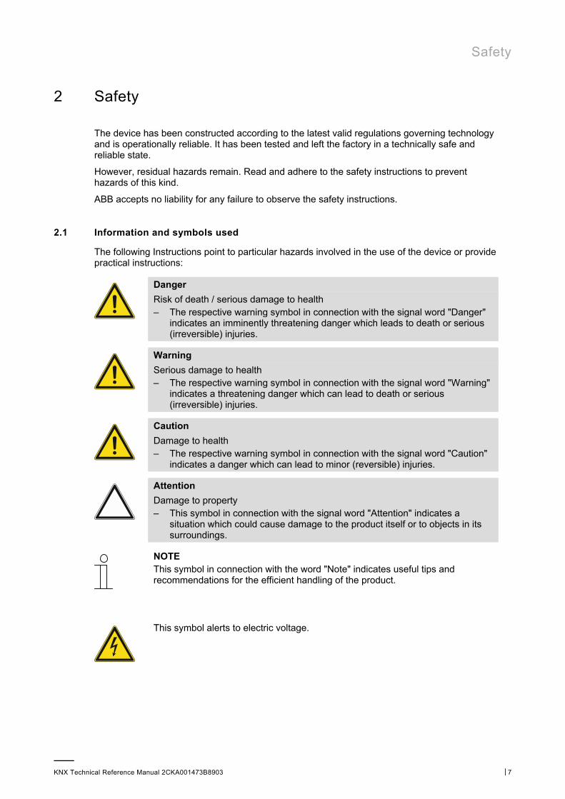
Danger
Risk of death / serious damage to health – The respective warning symbol in connection with the signal word "Danger"
indicates an imminently threatening danger which leads to death or serious (irreversible) injuries.
Warning
Serious damage to health – The respective warning symbol in connection with the signal word "Warning"
indicates a threatening danger which can lead to death or serious (irreversible) injuries.
Caution
Damage to health – The respective warning symbol in connection with the signal word "Caution"
indicates a danger which can lead to minor (reversible) injuries.
Attention
Damage to property – This symbol in connection with the signal word "Attention" indicates a
situation which could cause damage to the product itself or to objects in its surroundings.
NOTE This symbol in connection with the word "Note" indicates useful tips and recommendations for the efficient handling of the product.
This symbol alerts to electric voltage.
Safety
KNX Technical Reference Manual 2CKA001473B8903 │8
2.2 Intended use
The Busch-ControlTouch® is designed only for interior areas of buildings. The devices permit the easy and direct operation of building automation systems using Apple or Android or a laptop/desktop PC. In the process, control is implemented through a direct KNX connection (inside the building) or via the Internet (outside the building). The associated app detects the status of switches and dimmers, for example. As a result, they can be opened and viewed without complex programming using the app.
The device is intended for the following:
■ operation according to the listed technical data.
■ installation in dry interior rooms and only on mounting rails according to DIN EN 60715,
■ Use with the connecting options available on the device.
The intended use also includes adherence to all specifications in this mnaual.
2.3 Improper use
Each use not listed in Chapter 2.2 “Intended use“ on page 8 is deemed improper use and can lead to personal injury and damage to property.
ABB is not liable for damages caused by use deemed contrary to the intended use of the device. The associated risk is borne exclusively by the user/operator.
The device is not intended for the following:
■ Unauthorized structural changes
■ Repairs
■ Outdoor use
■ The use in bathroom areas
■ Insert with an additional bus coupler
2.4 Target group / Qualifications of personnel
2.4.1 Installation, commissioning and maintenance
Installation, commissioning and maintenance of the device must only be carried out by trained and properly qualified electrical installers.
The electrical installer must have read and understood the manual and follow the instructions provided.
The electrical installer must adhere to the valid national regulations in his/her country governing the installation, functional test, repair and maintenance of electrical products.
The electrical installer must be familiar with and correctly apply the "five safety rules" (DIN VDE 0105, EN 50110):
1. Disconnect
2. Secure against being re-connected
3. Ensure there is no voltage
4. Connect to earth and short-circuit
5. Cover or barricade adjacent live parts
Safety
KNX Technical Reference Manual 2CKA001473B8903 │9
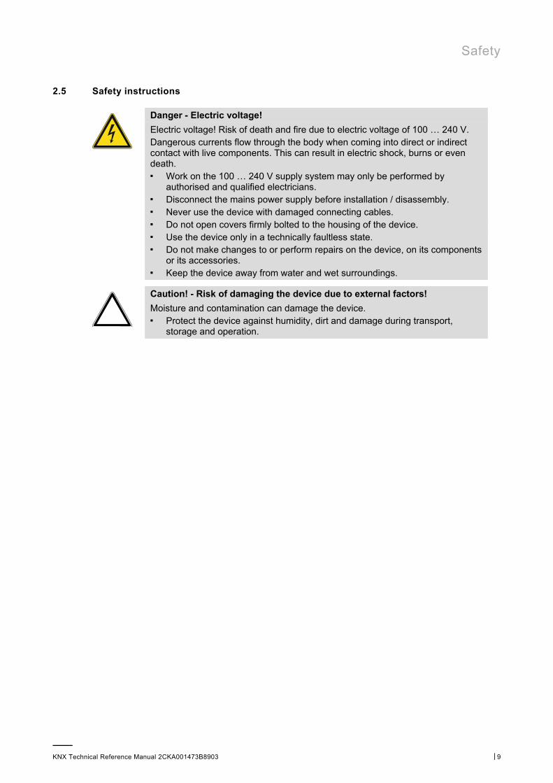
2.5 Safety instructions
Danger - Electric voltage!
Electric voltage! Risk of death and fire due to electric voltage of 100 … 240 V. Dangerous currents flow through the body when coming into direct or indirect contact with live components. This can result in electric shock, burns or even death. ■ Work on the 100 … 240 V supply system may only be performed by
authorised and qualified electricians. ■ Disconnect the mains power supply before installation / disassembly. ■ Never use the device with damaged connecting cables. ■ Do not open covers firmly bolted to the housing of the device. ■ Use the device only in a technically faultless state. ■ Do not make changes to or perform repairs on the device, on its components
or its accessories. ■ Keep the device away from water and wet surroundings.
Caution! - Risk of damaging the device due to external factors!
Moisture and contamination can damage the device. ■ Protect the device against humidity, dirt and damage during transport,
storage and operation.

Information on protection of the environment
KNX Technical Reference Manual 2CKA001473B8903 │10
3 Information on protection of the environment
3.1 Environment
Consider the protection of the environment!
Used electric and electronic devices must not be disposed of with domestic waste. – The device contains valuable raw materials which can be recycled.
Therefore, dispose of the device at the appropriate collecting depot.
All packaging materials and devices bear the markings and test seals for proper disposal. Always dispose of the packaging material and electric devices and their components via the authorized collecting depots and disposal companies.
The products meet the legal requirements, in particular the laws governing electronic and electrical devices and the REACH ordinance.
(EU Directive 2012/19/EU WEEE and 2011/65/EU RoHS)
(EU REACH ordinance and law for the implementation of the ordinance (EC) No.1907/2006).
Setup and function
KNX Technical Reference Manual 2CKA001473B8903 │11
4 Setup and function
4.1 Device overview
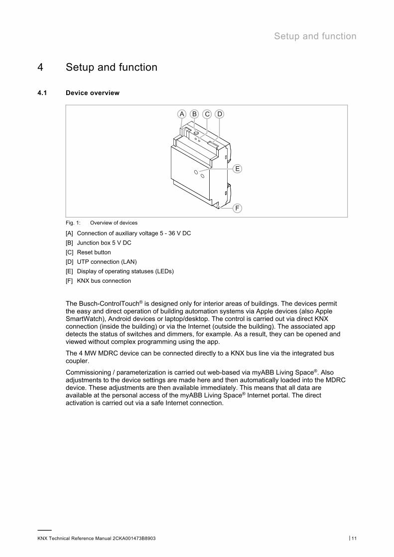
Fig. 1: Overview of devices
[A] Connection of auxiliary voltage 5 - 36 V DC
[B] Junction box 5 V DC
[C] Reset button
[D] UTP connection (LAN)
[E] Display of operating statuses (LEDs)
[F] KNX bus connection
The Busch-ControlTouch® is designed only for interior areas of buildings. The devices permit the easy and direct operation of building automation systems via Apple devices (also Apple SmartWatch), Android devices or laptop/desktop. The control is carried out via direct KNX connection (inside the building) or via the Internet (outside the building). The associated app detects the status of switches and dimmers, for example. As a result, they can be opened and viewed without complex programming using the app.
The 4 MW MDRC device can be connected directly to a KNX bus line via the integrated bus coupler.
Commissioning / parameterization is carried out web-based via myABB Living Space®. Also adjustments to the device settings are made here and then automatically loaded into the MDRC device. These adjustments are then available immediately. This means that all data are available at the personal access of the myABB Living Space® Internet portal. The direct activation is carried out via a safe Internet connection.
Setup and function
KNX Technical Reference Manual 2CKA001473B8903 │12
Additional product features:
■ Easy visualization through list menu and colour concept
■ Changes can be made online
■ Simple APP remote control for KNX (also via VPN connection)
■ Simple control of KNX functions in the building
■ Integration of UPnP devices (e.g., Sonos)
■ Integration of Sonos and Philips Hue lamps
■ Integration of IP cameras
■ Creation of own scripts for logical functions (e.g. IF then ELSE)
■ Scenes and time programs can be edited and/or adjusted by the end customer
■ Use as alarm system
■ Alarm and error messages via push message
NOTE A separate power adapter is required for the power supply (e.g. priOn power adaptor 6358-101).
4.2 Scope of supply
Included in the scope of delivery are:
■ 4 MW MDRC device
■ UTP cable
The app can be downloaded via the Apple Store or Google Store free of charge. A power adapter for the power supply (e.g. priOn power adaptor 6358-101) must be ordered separately!
4.3 Overview of types
Article number Product name Usage
6136/APP-500
Busch-ControlTouch® Residential buildings, small to medium-sized commercial buildings, office buildings and hotels.
Table 1: Overview of types
Setup and function
KNX Technical Reference Manual 2CKA001473B8903 │13
4.4 Functions
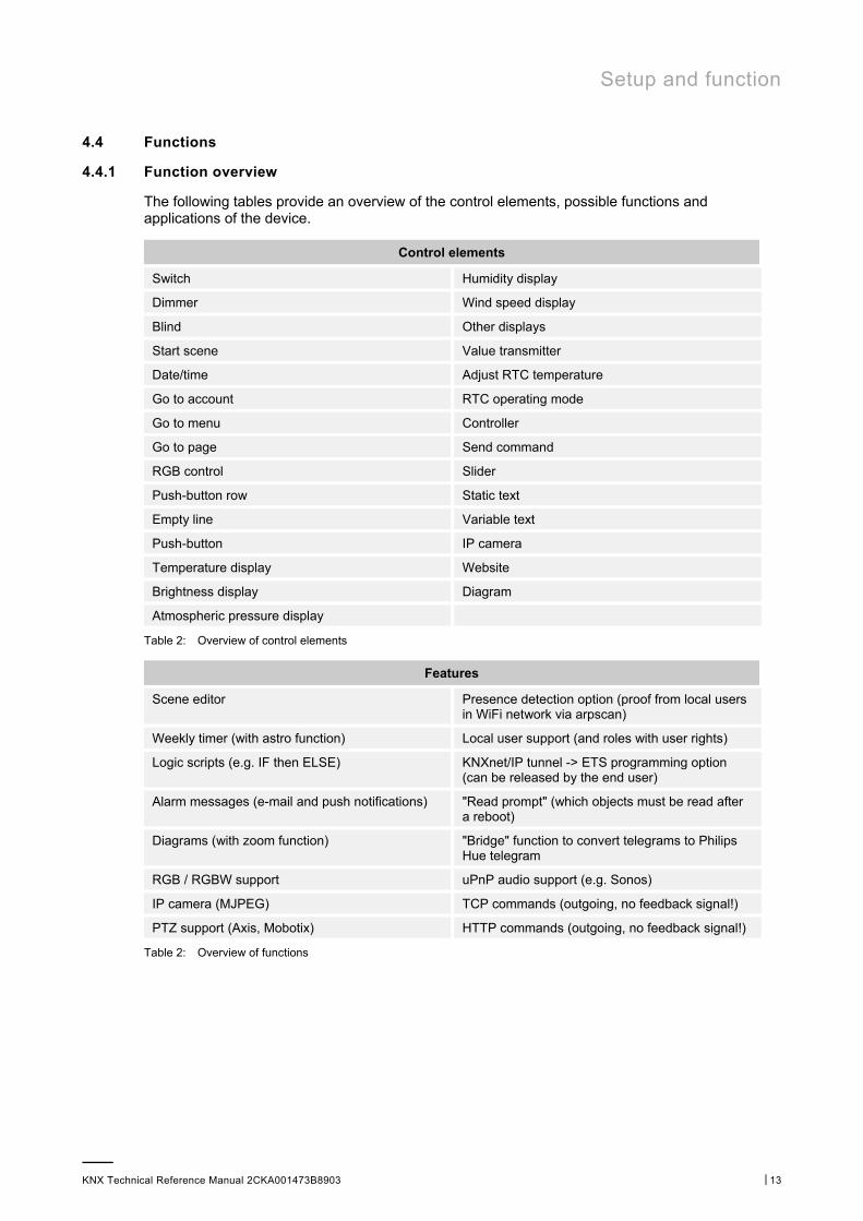
4.4.1 Function overview
The following tables provide an overview of the control elements, possible functions and applications of the device.
Control elements
Switch Humidity display
Dimmer Wind speed display
Blind Other displays
Start scene Value transmitter
Date/time Adjust RTC temperature
Go to account RTC operating mode
Go to menu Controller
Go to page Send command
RGB control Slider
Push-button row Static text
Empty line Variable text
Push-button IP camera
Temperature display Website
Brightness display Diagram
Atmospheric pressure display
Table 2: Overview of control elements
Features
Scene editor Presence detection option (proof from local users in WiFi network via arpscan)
Weekly timer (with astro function) Local user support (and roles with user rights)
Logic scripts (e.g. IF then ELSE) KNXnet/IP tunnel -> ETS programming option (can be released by the end user)
Alarm messages (e-mail and push notifications) "Read prompt" (which objects must be read after a reboot)
Diagrams (with zoom function) "Bridge" function to convert telegrams to Philips Hue telegram
RGB / RGBW support uPnP audio support (e.g. Sonos)
IP camera (MJPEG) TCP commands (outgoing, no feedback signal!)
PTZ support (Axis, Mobotix) HTTP commands (outgoing, no feedback signal!)
Table 2: Overview of functions
Setup and function
KNX Technical Reference Manual 2CKA001473B8903 │14
Various commands, e.g. for Sonos functions, can be activated using the uPnP function "UPNP COMMANDS". These commands appear automatically if a corresponding uPnP device (e.g. Sonos loudspeaker) supporting these features is connected.
These extra functions (commands) can be triggered by a scene, a time program, an action (trigger) or a script.
4.4.2 Description of functions
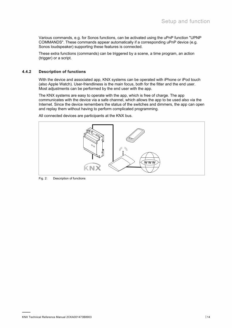
With the device and associated app, KNX systems can be operated with iPhone or iPod touch (also Apple Watch). User-friendliness is the main focus, both for the fitter and the end user. Most adjustments can be performed by the end user with the app.
The KNX systems are easy to operate with the app, which is free of charge. The app communicates with the device via a safe channel, which allows the app to be used also via the Internet. Since the device remembers the status of the switches and dimmers, the app can open and replay them without having to perform complicated programming.
All connected devices are participants at the KNX bus.
Fig. 2: Description of functions
Technical data
KNX Technical Reference Manual 2CKA001473B8903 │15
5 Technical data
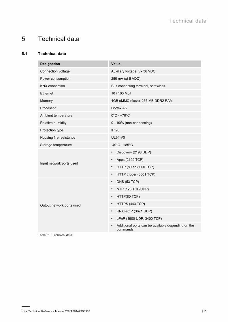
5.1 Technical data
Designation Value
Connection voltage Auxiliary voltage: 5 - 36 VDC
Power consumption 250 mA (at 5 VDC)
KNX connection Bus connecting terminal, screwless
Ethernet 10 / 100 Mbit
Memory 4GB eMMC (flash), 256 MB DDR2 RAM
Processor Cortex A5
Ambient temperature 0°C - +70°C
Relative humidity 0 – 90% (non-condensing)
Protection type IP 20
Housing fire resistance UL94-V0
Storage temperature -40°C - +85°C
Input network ports used
■ Discovery (2198 UDP)
■ Apps (2199 TCP)
■ HTTP (80 en 8000 TCP)
■ HTTP trigger (8001 TCP)
Output network ports used
■ DNS (53 TCP)
■ NTP (123 TCP/UDP)
■ HTTP(80 TCP)
■ HTTPS (443 TCP)
■ KNXnet/IP (3671 UDP)
■ uPnP (1900 UDP, 3400 TCP)
■ Additional ports can be available depending on the commands.
Table 3: Technical data

Technical data
KNX Technical Reference Manual 2CKA001473B8903 │16
5.2 Dimensional drawings
Fig. 3: Dimensions Busch-ControlTouch®
NOTE All dimensions are in mm.
Connection, installation / mounting
KNX Technical Reference Manual 2CKA001473B8903 │17
6 Connection, installation / mounting
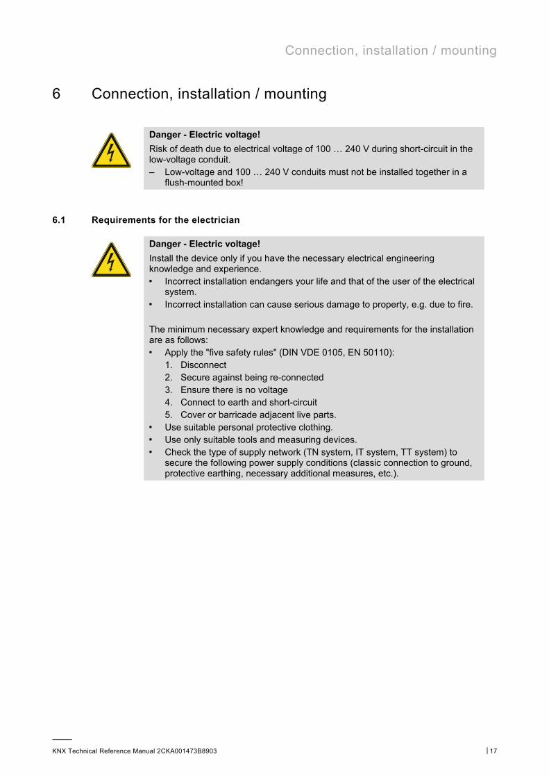
Danger - Electric voltage!
Risk of death due to electrical voltage of 100 … 240 V during short-circuit in the low-voltage conduit. – Low-voltage and 100 … 240 V conduits must not be installed together in a
flush-mounted box!
6.1 Requirements for the electrician
Danger - Electric voltage!
Install the device only if you have the necessary electrical engineering knowledge and experience. ■ Incorrect installation endangers your life and that of the user of the electrical
system. ■ Incorrect installation can cause serious damage to property, e.g. due to fire. The minimum necessary expert knowledge and requirements for the installation are as follows: ■ Apply the "five safety rules" (DIN VDE 0105, EN 50110):
1. Disconnect 2. Secure against being re-connected 3. Ensure there is no voltage 4. Connect to earth and short-circuit 5. Cover or barricade adjacent live parts.
■ Use suitable personal protective clothing. ■ Use only suitable tools and measuring devices. ■ Check the type of supply network (TN system, IT system, TT system) to
secure the following power supply conditions (classic connection to ground, protective earthing, necessary additional measures, etc.).
Connection, installation / mounting
KNX Technical Reference Manual 2CKA001473B8903 │18
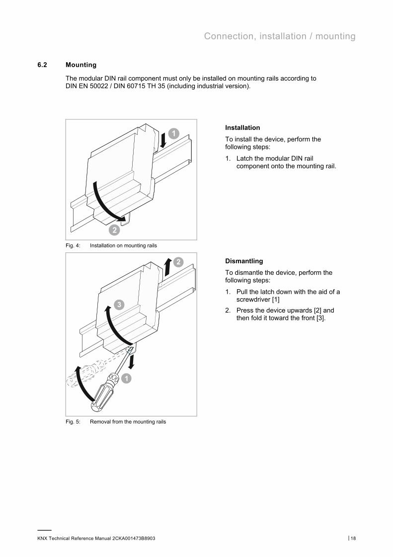
6.2 Mounting
The modular DIN rail component must only be installed on mounting rails according to DIN EN 50022 / DIN 60715 TH 35 (including industrial version).
Installation
To install the device, perform the following steps:
1. Latch the modular DIN rail component onto the mounting rail.
Fig. 4: Installation on mounting rails
Dismantling
To dismantle the device, perform the following steps:
1. Pull the latch down with the aid of a screwdriver [1]
2. Press the device upwards [2] and then fold it toward the front [3].
Fig. 5: Removal from the mounting rails
Connection, installation / mounting
KNX Technical Reference Manual 2CKA001473B8903 │19
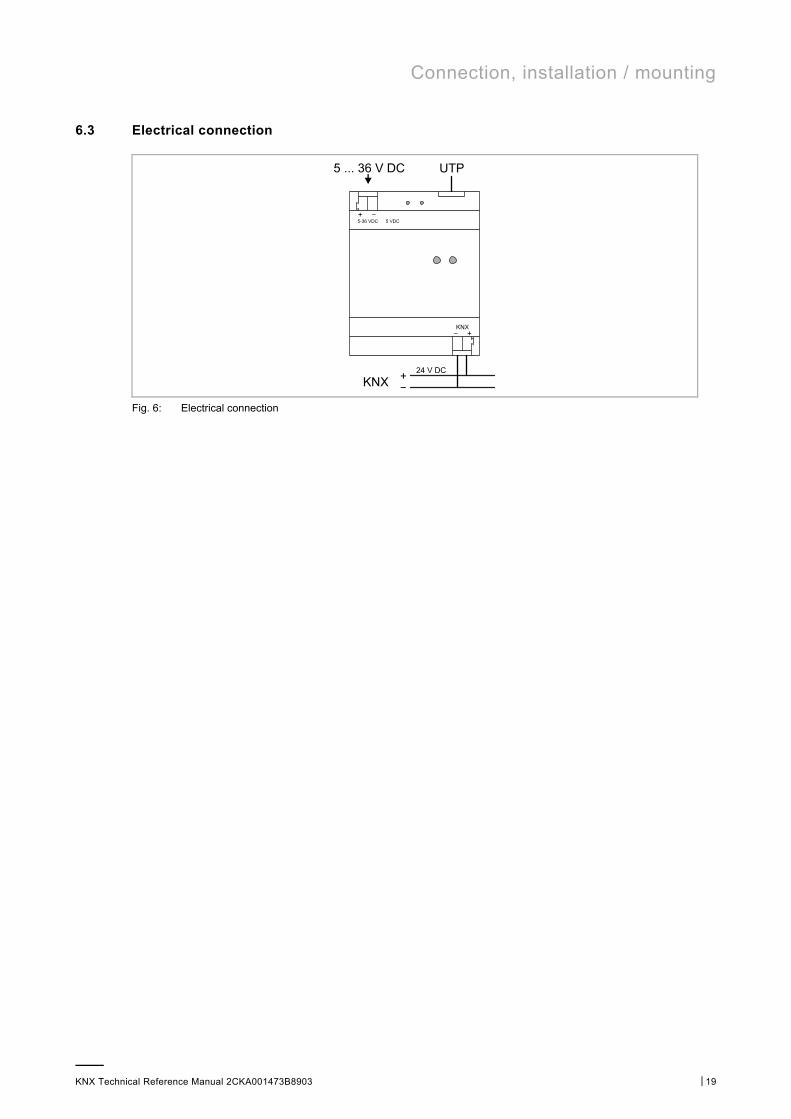
6.3 Electrical connection
Fig. 6: Electrical connection
Operation
KNX Technical Reference Manual 2CKA001473B8903 │20
7 Operation
7.1 Extended operation
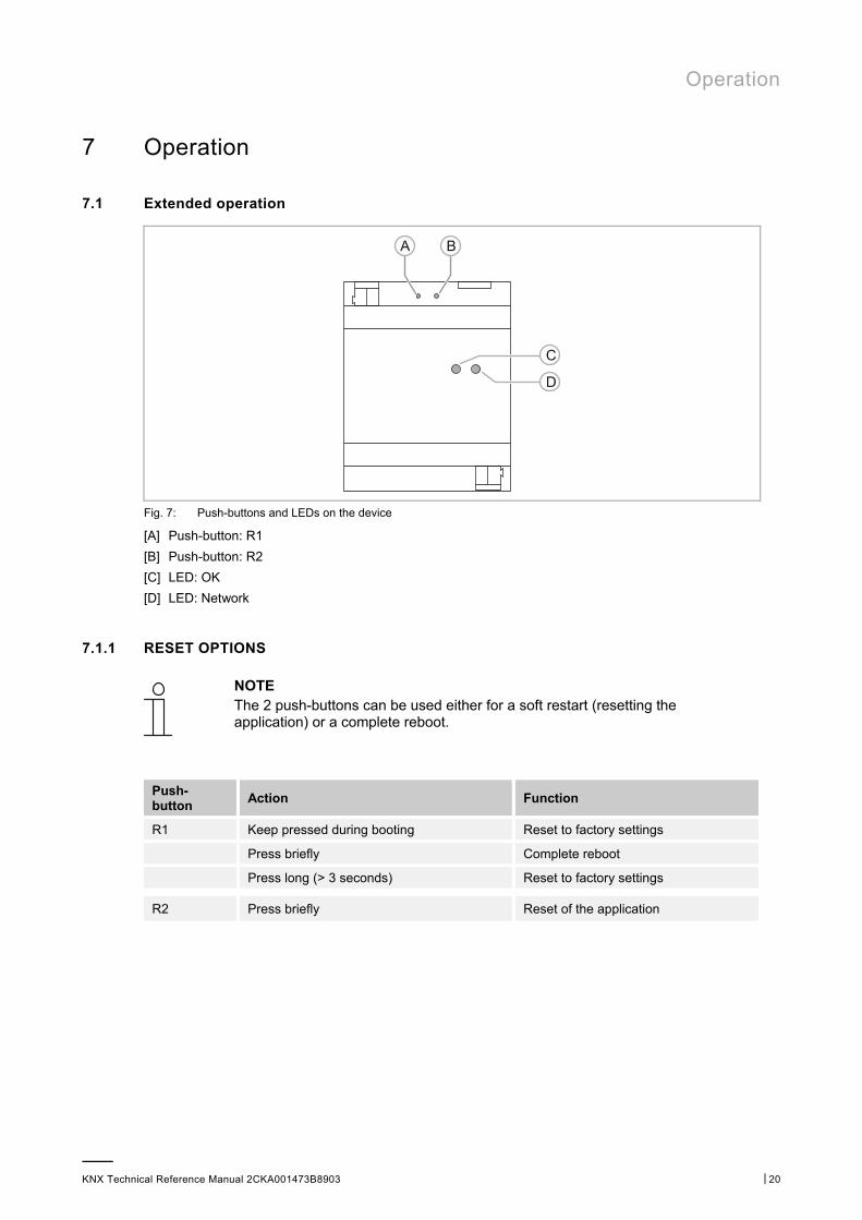
Fig. 7: Push-buttons and LEDs on the device
[A] Push-button: R1
[B] Push-button: R2
[C] LED: OK
[D] LED: Network
7.1.1 RESET OPTIONS
NOTE The 2 push-buttons can be used either for a soft restart (resetting the application) or a complete reboot.
Push-button
Action Function
R1 Keep pressed during booting Reset to factory settings
Press briefly Complete reboot
Press long (> 3 seconds) Reset to factory settings
R2 Press briefly Reset of the application
Operation
KNX Technical Reference Manual 2CKA001473B8903 │21
7.1.2 Operating statuses
NOTE
The 2 LEDs show one of the following, – Operational readiness – Status of LAN connection – Status of KNX connection
LED Colour Display mode Function
"OK" Green Flashes slowly Booting or shutting down
Green Lit constantly Application is ready to start
"Network" Green Flashes slowly Normal procedure - OK
Yellow Flashes slowly No KNX connection
Red Flashes fast LAN problem, no network
Red / green Flashes at intervals
No Internet connection, only LAN connection
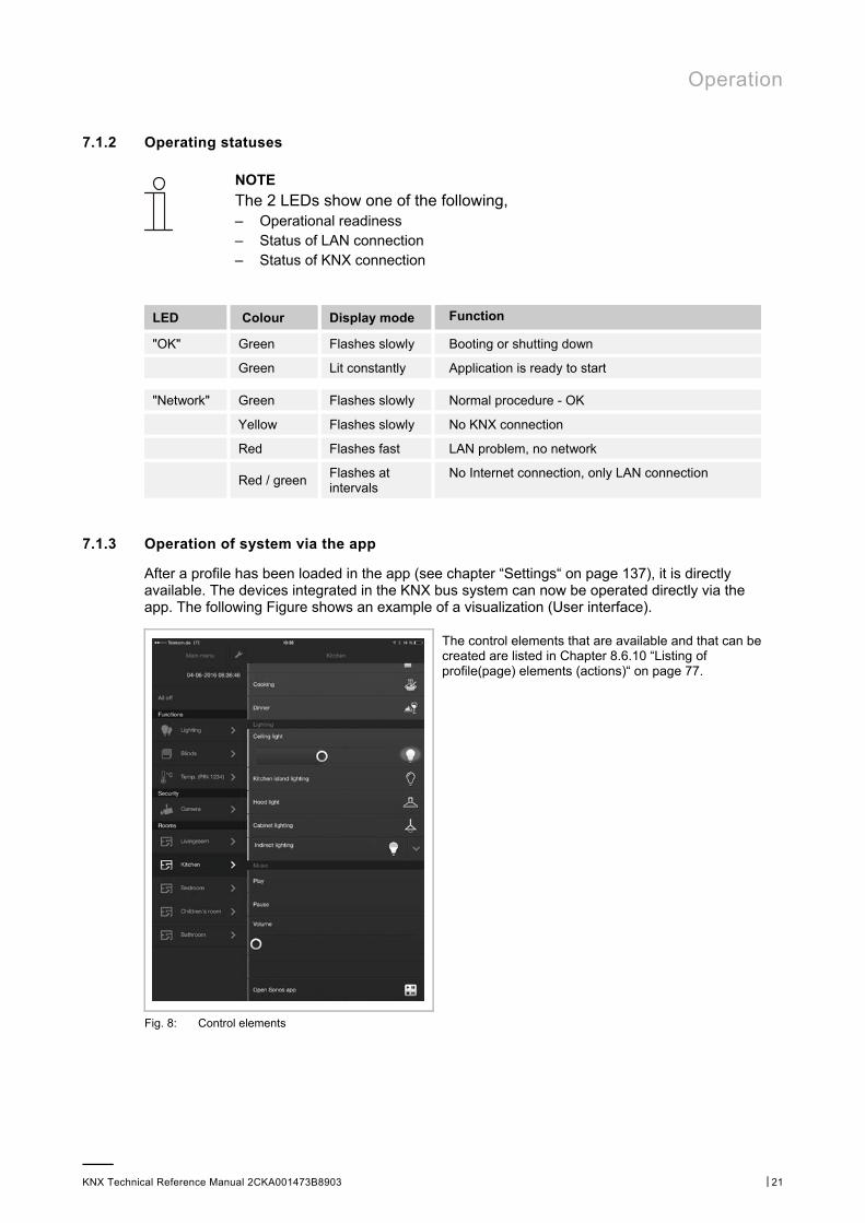
7.1.3 Operation of system via the app
After a profile has been loaded in the app (see chapter “Settings“ on page 137), it is directly available. The devices integrated in the KNX bus system can now be operated directly via the app. The following Figure shows an example of a visualization (User interface).
The control elements that are available and that can be created are listed in Chapter 8.6.10 “Listing of profile(page) elements (actions)“ on page 77.
Fig. 8: Control elements

Commissioning
KNX Technical Reference Manual 2CKA001473B8903 │22
a)
1)
8 Commissioning
8.1 Brief instructions for typical commissioning
8.1.1.1 Implementation by fitter / expert
Login at myABB Living Space®
Register device for access (Account) myABB Living Space® (input of serial number)
Cre
atio
n vi
a w
eb
conf
igur
atio
n p
age
Create app access (account) Allocation of name and password
Takeover of project data from ETS (setting group addresses)
Create visualization
Install device at end user (+ network connection)
Locate device in network via IP locator
Commissioning
KNX Technical Reference Manual 2CKA001473B8903 │23
b)
c)
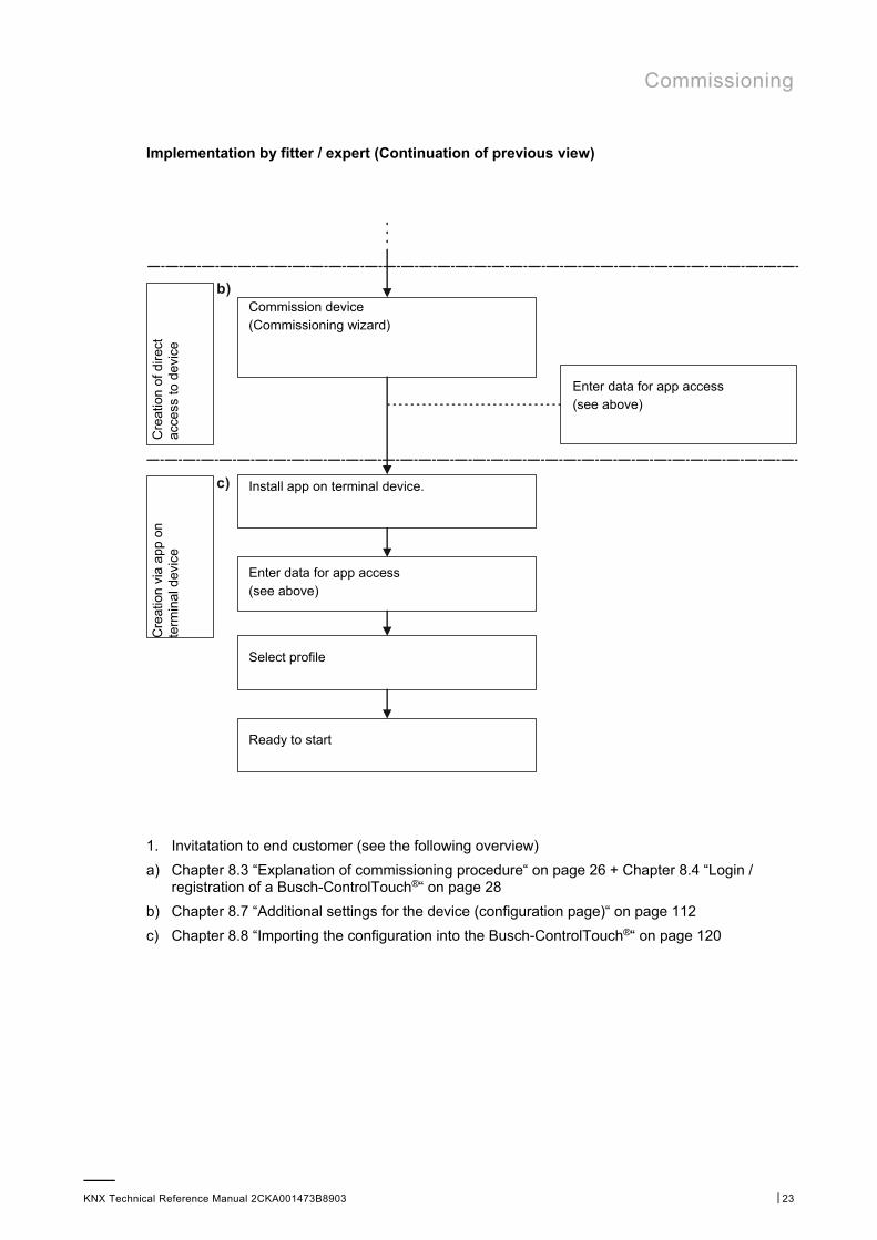
Implementation by fitter / expert (Continuation of previous view)
Cre
atio
n of
dir
ect
acce
ss to
dev
ice
Commission device (Commissioning wizard)
Enter data for app access (see above)
Cre
atio
n vi
a a
pp
on
term
inal
dev
ice
Install app on terminal device.
Enter data for app access (see above)
Select profile
Ready to start
1. Invitatation to end customer (see the following overview)
a) Chapter 8.3 “Explanation of commissioning procedure“ on page 26 + Chapter 8.4 “Login / registration of a Busch-ControlTouch®“ on page 28
b) Chapter 8.7 “Additional settings for the device (configuration page)“ on page 112
c) Chapter 8.8 “Importing the configuration into the Busch-ControlTouch®“ on page 120
Commissioning
KNX Technical Reference Manual 2CKA001473B8903 │24
a)
b)
2)
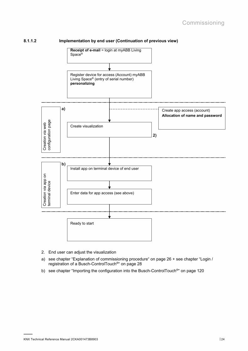
8.1.1.2 Implementation by end user (Continuation of previous view)
Receipt of e-mail = login at myABB Living Space®
Register device for access (Account) myABB Living Space® (entry of serial number) personalizing
Cre
atio
n vi
a w
eb
conf
igur
atio
n p
age
Create app access (account) Allocation of name and password
Create visualization
Cre
atio
n vi
a a
pp
on
term
inal
dev
ice
Install app on terminal device of end user
Enter data for app access (see above)
Ready to start
2. End user can adjust the visualization
a) see chapter “Explanation of commissioning procedure“ on page 26 + see chapter “Login / registration of a Busch-ControlTouch®“ on page 28
b) see chapter “Importing the configuration into the Busch-ControlTouch®“ on page 120
Commissioning
KNX Technical Reference Manual 2CKA001473B8903 │25
1)
2)
1)3)
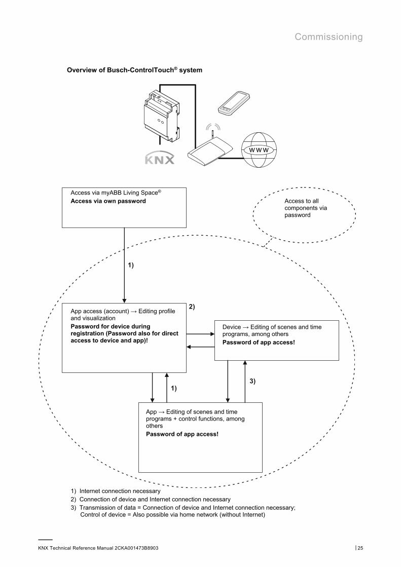
Overview of Busch-ControlTouch® system
Access via myABB Living Space® Access via own password
Access to all components via password
App access (account) → Editing profile and visualization Password for device during registration (Password also for direct access to device and app)!
Device → Editing of scenes and time programs, among others Password of app access!
App → Editing of scenes and time programs + control functions, among others Password of app access!
1) Internet connection necessary 2) Connection of device and Internet connection necessary 3) Transmission of data = Connection of device and Internet connection necessary;
Control of device = Also possible via home network (without Internet)
Commissioning
KNX Technical Reference Manual 2CKA001473B8903 │26
8.2 Preparatory steps
NOTE The devices are a product of the KNX system and meet KNX guidelines. Detailed expert knowledge by means of KNX training sessions for a better understanding is assumed. And, for all additional components of building automation (e.g. Philips Hue), the appropriate know-how must be available if they are to be used in the system.
1. Assigning group addresses:
– The group addresses are assigned in connection with the ETS. This is carried out by the fitter.
2. Exporting project ETS4 or ETS5!
– This file can be loaded into the profile of the Busch-ControlTouch®. This is carried out by the fitter.
8.3 Explanation of commissioning procedure
This chapter explains the working steps necessary for commissioning a Busch-ControlTouch®. It is directed at the implementing fitter (expert) and at his end customer. Each device must first be registered by an "Expert", to subsequently enable the end customer to carry out his individual configuration settings for his device. That is why the fitter must create his access to the myABB Living Space® and register himself. Also the end customer can let himself be registered. After the fitter has registered his device, he can generate an automatic mail to the end customer. This mail contains a link on the registration page. Here the end customer can also register himself for personal access to this device.
The commissioning procedure is described as follows:
1. Registering the device
– Registration in advance is required for installation/configuration. This is carried out via myABB Living Space® (for an explanation see Chapter 8.4 “Login / registration of a Busch-ControlTouch®“ on page 28) This grants one personal access for the device on the commissioning server.
NOTE Attention! This is not direct commissioning of the device.
2. Configuration
– Configuration is carried out via myABB Living Space® in a web browser. This software is used to create the system configuration.
– The system configuration is saved on a central server and is respectively downloaded from the Busch-ControlTouch® KNX.
– Group addresses are imported from ETS 4, ETS5 or higher by importing the KNX project directly to the commissioning server.
– Additional optional extras, such as Philips Hue, can be configured separately. However, for this the components must be connected with the system.
3. Connection of devices (for electrical connection of Busch-ControlTouch® see Chapter 6.3 “Electrical connection“ on page 19)
Additional components of building automation (e.g. Philips Hue) must be installed.
Commissioning
KNX Technical Reference Manual 2CKA001473B8903 │27
NOTE All the devices of the system must be correctly wired and connected to the bus line! The Busch-ControlTouch must be integrated in the network. Only then is voltage to be applied to the device.
4. Commissioning of the device via direct access to it.
5. Initialization
– Transmission of individually configured data to the device (system).
6. Installing and setup of app.
NOTE The app for controlling the connected KNX devices can be downloaded from Apple Store or Google Store. An explanation about operation is available in Chapter 7.1.3 “Operation of system via the app“ on page 21.
8.3.1 Overview of configuration
The configuration can be divided into 4 partial components:
1. Device (Busch-ControlTouch®)
The device must be registered by the fitter. This forms the basis for the next configuration steps. Finally the device can also be registered by the end customer to carry out customer-specific changes or supplementations.
2. Project
The project includes the current technical configuration (system configuration) for the building automation system and the group addresses that are part of the project. All devices contained in the system (also add-on components such as cameras, for example) are defined here. The system components are enabled for the device and assigned to it during the transmission of the project to a Busch-ControlTouch®.
3. Profile
The profile includes the form of the visualization (user interface) for smartphones and tablets for operating the building automation system via the Busch-ControlTouch®. The visualization is enabled for the device and assigned to it during the transmission of the profile to a Busch-ControlTouch®.
4. Pages
Each profile has a start page (menu page) and generally several follow-on pages. The follow-on pages are equipped with actions (commands), which can be selected on the relevant page. This, for example, creates a page for each room. The pages therefore are the different visualization interfaces which serve for the control and operation of the profile.

Commissioning
KNX Technical Reference Manual 2CKA001473B8903 │28
NOTE The fitter (expert) can create the project and transmit it to the device. The fitter (expert) can, of course, manage several projects and the device via an access. He also has access to the configuration environment of the end customer. Caution! The end customer can block the access to the profiles for the expert by means of his personal access via myABB Living Space®. Open the application "Busch-ControlTouch" (path: start page -> Service & Tools -> myABB Living Space® -> My installations -> Busch-ControlTouch®). In case of several devices, select the appropriate device from the list. The access can be blocked via the "Devices" tab by activating the function "Limited access for expert".
NOTE The end customer can appropriately adjust the project and the associated pages. There is also the option of using several devices and profiles in parallel. The profile which is to be assigned to the device can be selected on the smartphone or the tablet.
The final sequence of the configuration is described in detail in the following, after the device has been registered and a profile has been created. The Busch-ControlTouch® must be configured appropriately before it can be used.
1. Preparation of a project with pages
2. Creation of pages. These are equipped with actions (commands), which can be selected onthe relevant page.
3. Creation of the start pages (menu pages)
4. Importing the configuration into the Busch-ControlTouch®
5. Optional creation of scenes and time programs (directly in the device)
6. Installation and setting of the app
8.4 Login / registration of a Busch-ControlTouch®
The registration of your product is important to safeguard your warranty claims. The registration is also necessary to configure your device. Each device must first be registered by an installer (expert), to subsequently enable the end customer to carry out his individual configuration settings for his device. The first login must be carried out if access to the registration page is not yet available. That is why the fitter must create his access to the myABB Living Space® and register himself. Also the end customer can let himself be registered. After the fitter has registered his device, he can generate an automatic mail to the end customer. This mail contains a link on the registration page. Here the end customer can also register himself for personal access to this device.
Commissioning
KNX Technical Reference Manual 2CKA001473B8903 │29
8.4.1 First login of the Busch-ControlTouch® at myABB Living Space® without an available access
8.4.1.1 Registration and login
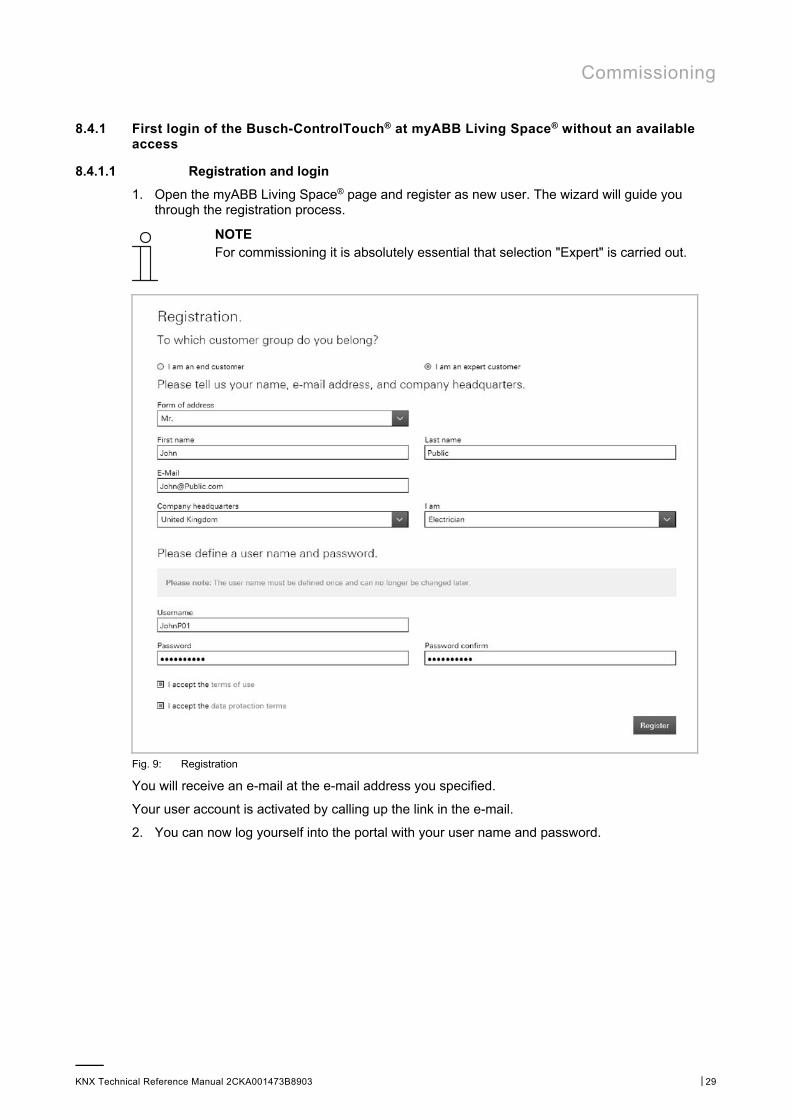
1. Open the myABB Living Space® page and register as new user. The wizard will guide you through the registration process.
NOTE For commissioning it is absolutely essential that selection "Expert" is carried out.
Fig. 9: Registration
You will receive an e-mail at the e-mail address you specified.
Your user account is activated by calling up the link in the e-mail.
2. You can now log yourself into the portal with your user name and password.
Commissioning
KNX Technical Reference Manual 2CKA001473B8903 │30
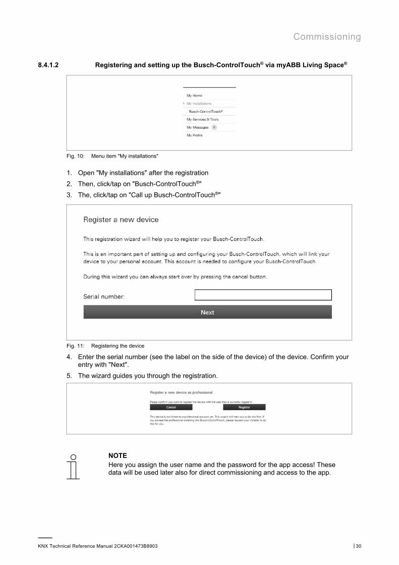
8.4.1.2 Registering and setting up the Busch-ControlTouch® via myABB Living Space®
Fig. 10: Menu item "My installations"
1. Open "My installations" after the registration
2. Then, click/tap on "Busch-ControlTouch®"
3. The, click/tap on "Call up Busch-ControlTouch®"
Fig. 11: Registering the device
4. Enter the serial number (see the label on the side of the device) of the device. Confirm your entry with "Next".
5. The wizard guides you through the registration.
NOTE Here you assign the user name and the password for the app access! These data will be used later also for direct commissioning and access to the app.
Commissioning
KNX Technical Reference Manual 2CKA001473B8903 │31
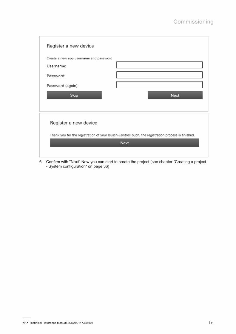
6. Confirm with "Next".Now you can start to create the project (see chapter “Creating a project - System configuration“ on page 36)
Commissioning
KNX Technical Reference Manual 2CKA001473B8903 │32
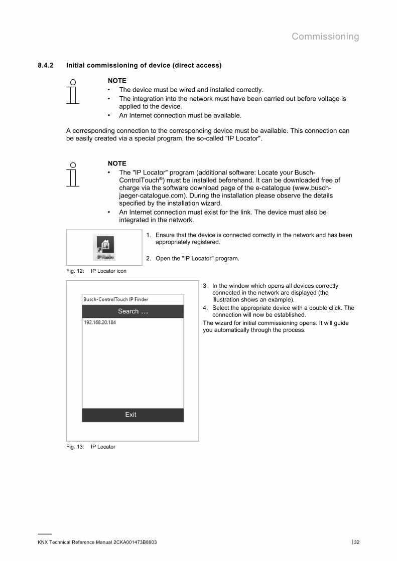
8.4.2 Initial commissioning of device (direct access)
NOTE ■ The device must be wired and installed correctly. ■ The integration into the network must have been carried out before voltage is
applied to the device. ■ An Internet connection must be available.
A corresponding connection to the corresponding device must be available. This connection can be easily created via a special program, the so-called "IP Locator".
NOTE ■ The "IP Locator" program (additional software: Locate your Busch-
ControlTouch®) must be installed beforehand. It can be downloaded free of charge via the software download page of the e-catalogue (www.busch-jaeger-catalogue.com). During the installation please observe the details specified by the installation wizard.
■ An Internet connection must exist for the link. The device must also be integrated in the network.
1. Ensure that the device is connected correctly in the network and has been appropriately registered.
2. Open the "IP Locator" program.
Fig. 12: IP Locator icon
3. In the window which opens all devices correctly connected in the network are displayed (the illustration shows an example).
4. Select the appropriate device with a double click. The connection will now be established.
The wizard for initial commissioning opens. It will guide you automatically through the process.
Fig. 13: IP Locator
Commissioning
KNX Technical Reference Manual 2CKA001473B8903 │33
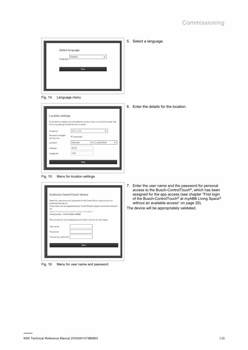
5. Select a language.
Fig. 14: Language menu
6. Enter the details for the location.
Fig. 15: Menu for location settings
7. Enter the user name and the password for personal access to the Busch-ControlTouch®, which has been assigned for the app access (see chapter “First login of the Busch-ControlTouch® at myABB Living Space® without an available access“ on page 29).
The device will be appropriately validated.
Fig. 16: Menu for user name and password
Commissioning
KNX Technical Reference Manual 2CKA001473B8903 │34
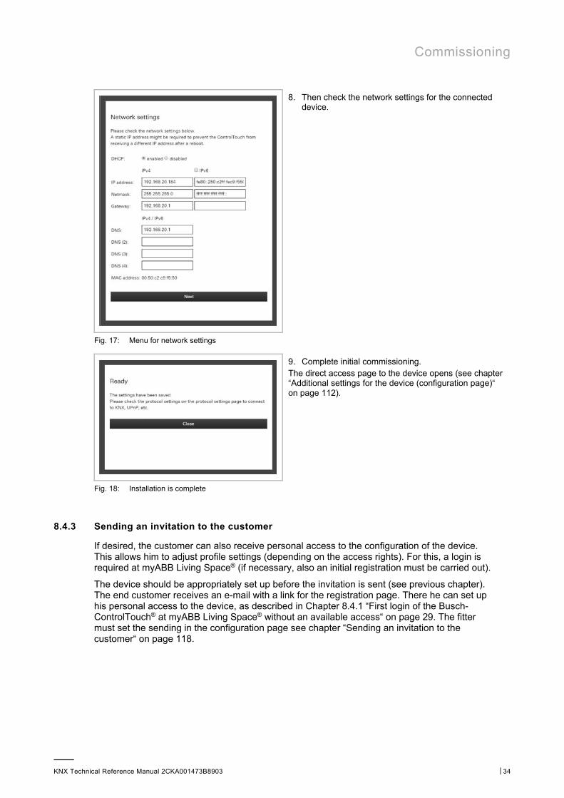
8. Then check the network settings for the connected device.
Fig. 17: Menu for network settings
9. Complete initial commissioning. The direct access page to the device opens (see chapter “Additional settings for the device (configuration page)“ on page 112).
Fig. 18: Installation is complete
8.4.3 Sending an invitation to the customer
If desired, the customer can also receive personal access to the configuration of the device. This allows him to adjust profile settings (depending on the access rights). For this, a login is required at myABB Living Space® (if necessary, also an initial registration must be carried out).
The device should be appropriately set up before the invitation is sent (see previous chapter). The end customer receives an e-mail with a link for the registration page. There he can set up his personal access to the device, as described in Chapter 8.4.1 “First login of the Busch-ControlTouch® at myABB Living Space® without an available access“ on page 29. The fitter must set the sending in the configuration page see chapter “Sending an invitation to the customer“ on page 118.

Commissioning
KNX Technical Reference Manual 2CKA001473B8903 │35
8.4.4 Login of new Busch-ControlTouch® at myABB Living Space® with existing access
Login at the myABB Living Space® portal
NOTE The fitter (expert) can have access, but manage several devices via the access.
1. Open the page myABB Living Space®.
2. Log yourself into the portal with your user name and password.
Registering and setting up the 3. Busch-ControlTouch® via the myABB Living Space® portal:
No device has yet been registered. A device has already been registered.
After the login you are requested to admit the access to the Busch-ControlTouch®. a. To do this, tap on the corresponding
button.
a. Open the application "Busch-ControlTouch" (path: start page → Service & Tools → myABB Living Space® → My installations →Busch-ControlTouch®) and click on the following button:
b. Click on "+ Register a new device".
4. Then enter the serial number (see the label on the side of the device) of the device.
5. Confirm the entry.
The wizard guides you through the registration.
6. After the registration, follow the specifications in Chapter 8.4.2 “Initial commissioning of device (direct access)“ on page 32 and Chapter 8.4.3 “Sending an invitation to the customer“ on page 34.

Commissioning
KNX Technical Reference Manual 2CKA001473B8903 │36
8.5 Creating a project - System configuration
8.5.1 General information
Each project includes components of the building automation system. Each component consists of a combination of type, name and group address, to clearly identify the component.
The type (data type) of the component must harmonize with the characteristics of the building automation component for which it is to be used (e.g. switch for "Switch on the light").
The name of the component is important for the identification by the end customer. This allows an easy allocation of the component due to its clear designation (e.g. kitchen table lamp). The end customer can independently adjust the names via the visualisation interface (app).
The group address of the component is used for the functional allocation:
■ The sending group includes the group address to which a telegram is to be sent. A maximum of one sending group address can be used per component.
■ The status groups include one or several group addresses to display the status of a component. The sending group address is often also a status group.
■ The value includes the value that is to be sent or the value to which the Busch-ControlTouch® (building automation system) is to respond.
The group addresses are used by the different protocols of the building automation, e.g. Hue, etc. Details about these protocols are available in the corresponding chapters of this manual.
Note For each component it can be specified whether it is available to the end customer for use in scenes or to the timer (time programs). Normally all actuators (light, blind, etc.) that are triggered by normal switches should also be available for scenes and the timer.
By means of scenes the end customer can trigger a whole sequence of actions, with just one press of the switch, for example. The end customer can compile the scene personally. However, the fitter (expert) must create a basic structure of scenes beforehand to which the Busch-ControlTouch® (building automation system) appropriately responds. For this the Busch-ControlTouch® must receive the special group addresses and values. This means that when a KNX device (e.g. switch) sends a telegram to one of these addresses, for example, the Busch-ControlTouch® will then play this scene.
Note Scenes for which the fitter (expert) has specified a group address, cannot be deleted by the end customer.
Scenes can also be changed via the visualisation (app). Here the end customer can also adjust the names of the scenes.
Commissioning
KNX Technical Reference Manual 2CKA001473B8903 │37
Scenes can be set the current values of the components that they incorporate. To do this, a KNX teach-in telegram is sent for the relevant group address with the value change to the KNX bus.
Note ■ A long actuation on a scene element (device/visualisation (app)) must be
carried out. The scene will therefore not be played, but rather saved. ■ uPnP/TCP commands and executed scripts are not updated by this action. ■ Only one KNX project can be created and used for each device. However,
multiple devices can be logged in. Projects can thus be created in parallel for this.
8.5.2 Creating a project
NOTE Please note that when adjusting an existing project, or when an additional project is to be created, access must always take place via myABB Living Space®. Open the application "Busch-ControlTouch" (path: start page → Service & Tools → myABB Living Space® → My installations → Busch-ControlTouch®). In case of several devices, select the appropriate device from the list. The adjustments can be made via the "Projects" tab.
8.5.2.1 Opening the configuration page
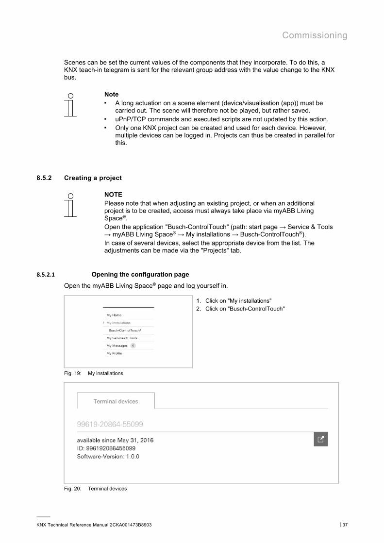
Open the myABB Living Space® page and log yourself in.
1. Click on "My installations" 2. Click on "Busch-ControlTouch"
Fig. 19: My installations
Fig. 20: Terminal devices
Commissioning
KNX Technical Reference Manual 2CKA001473B8903 │38
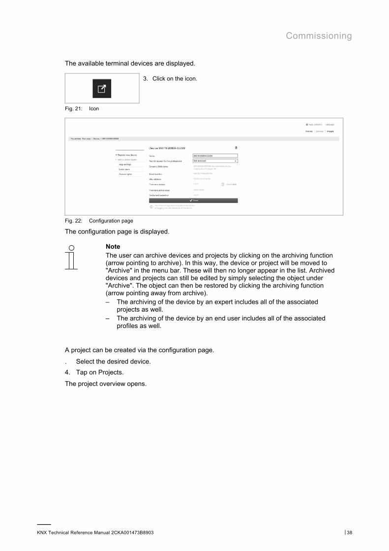
The available terminal devices are displayed.
3. Click on the icon.
Fig. 21: Icon
Fig. 22: Configuration page
The configuration page is displayed.
Note The user can archive devices and projects by clicking on the archiving function (arrow pointing to archive). In this way, the device or project will be moved to "Archive" in the menu bar. These will then no longer appear in the list. Archived devices and projects can still be edited by simply selecting the object under "Archive". The object can then be restored by clicking the archiving function (arrow pointing away from archive). – The archiving of the device by an expert includes all of the associated
projects as well. – The archiving of the device by an end user includes all of the associated
profiles as well.
A project can be created via the configuration page.
. Select the desired device.
4. Tap on Projects.
The project overview opens.

Commissioning
KNX Technical Reference Manual 2CKA001473B8903 │39
Fig. 23: Project overview
5. Tap on "+Add a new project".
A new project is created.
Note A standard project [standard project (device number)] is automatically created during the registration. This can also be used for editing.
6. Fill in the input fields according to the stipulations.
Note The fields for the group addresses need not be filled in. However, if necessary, "only sending" group addresses can be entered.
7. Confirm with "Change".
The specifications about the new project are saved.
8. Now carry out further adjustments for the project. Follow the details in the following sub-chapters.
Note The user can archive devices and projects by clicking on the archiving function (arrow pointing to archive). This moves the device to "Archive" in the menu bar. This will therefore no longer appear in the list. Archived devices and projects can still be edited by simply selecting the object under "Archive". The object can then be restored by clicking the archiving function (arrow pointing away from archive).
Commissioning
KNX Technical Reference Manual 2CKA001473B8903 │40
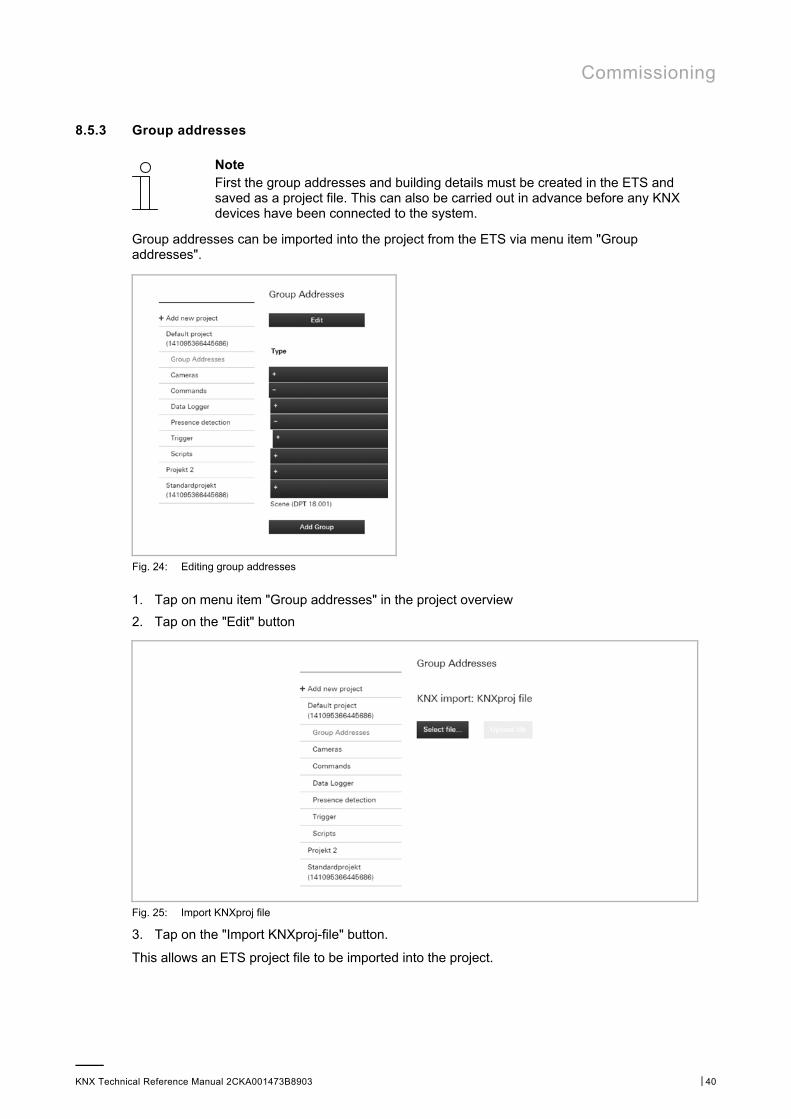
8.5.3 Group addresses
Note First the group addresses and building details must be created in the ETS and saved as a project file. This can also be carried out in advance before any KNX devices have been connected to the system.
Group addresses can be imported into the project from the ETS via menu item "Group addresses".
Fig. 24: Editing group addresses
1. Tap on menu item "Group addresses" in the project overview
2. Tap on the "Edit" button
Fig. 25: Import KNXproj file
3. Tap on the "Import KNXproj-file" button.
This allows an ETS project file to be imported into the project.

Commissioning
KNX Technical Reference Manual 2CKA001473B8903 │41
Fig. 26: >>Group addresses<<
4. Tap on the "Select file" button.
The desired project file can be selected via the dialogue window. It will then be imported into the project.
Commissioning
KNX Technical Reference Manual 2CKA001473B8903 │42
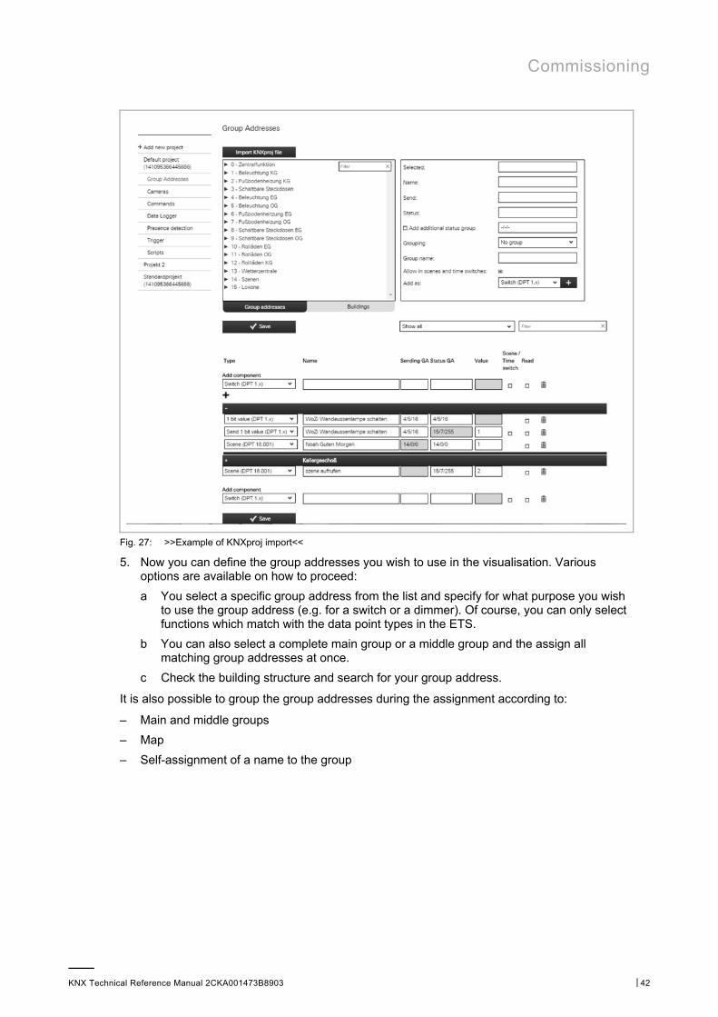
Fig. 27: >>Example of KNXproj import<<
5. Now you can define the group addresses you wish to use in the visualisation. Various options are available on how to proceed:
a You select a specific group address from the list and specify for what purpose you wish to use the group address (e.g. for a switch or a dimmer). Of course, you can only select functions which match with the data point types in the ETS.
b You can also select a complete main group or a middle group and the assign all matching group addresses at once.
c Check the building structure and search for your group address.
It is also possible to group the group addresses during the assignment according to:
– Main and middle groups
– Map
– Self-assignment of a name to the group
Commissioning
KNX Technical Reference Manual 2CKA001473B8903 │43
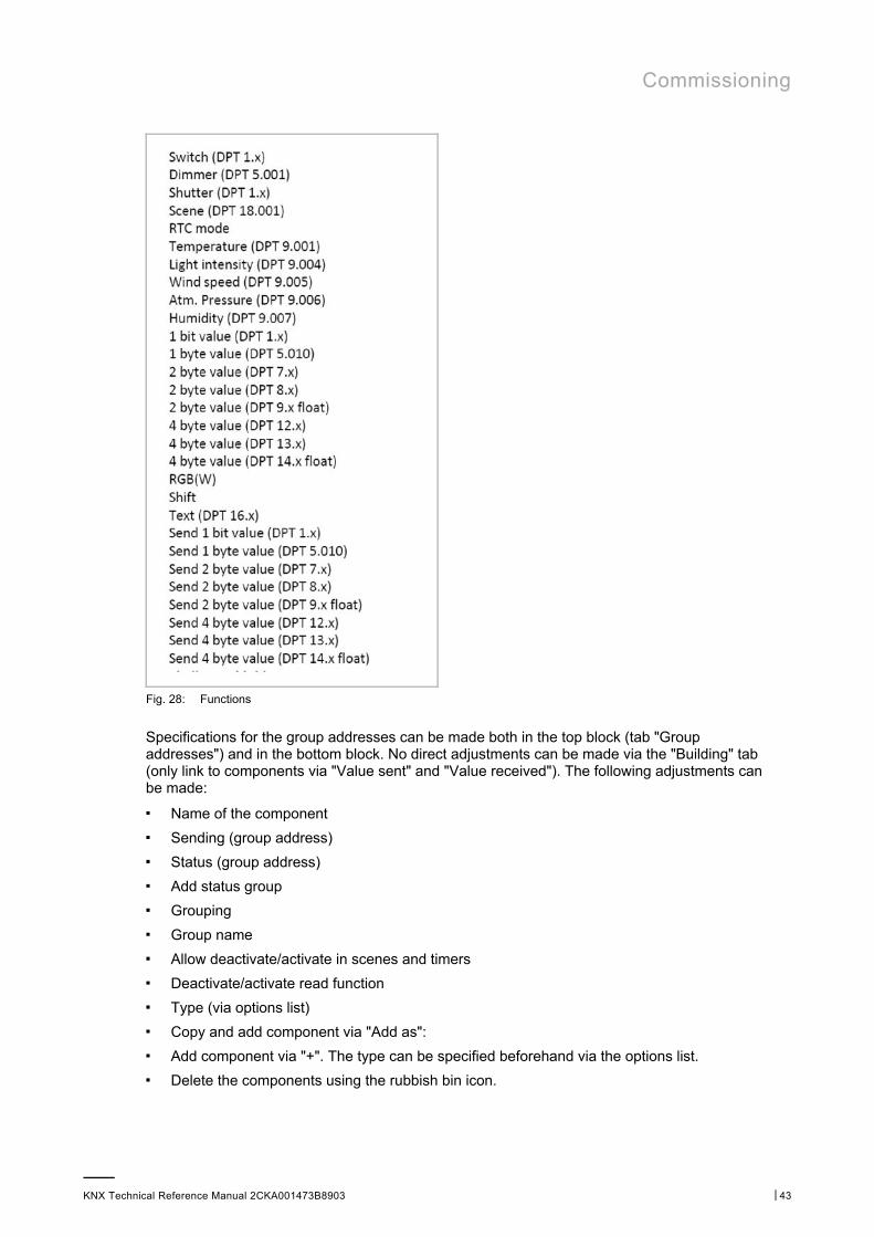
Fig. 28: Functions
Specifications for the group addresses can be made both in the top block (tab "Group addresses") and in the bottom block. No direct adjustments can be made via the "Building" tab (only link to components via "Value sent" and "Value received"). The following adjustments can be made:
■ Name of the component
■ Sending (group address)
■ Status (group address)
■ Add status group
■ Grouping
■ Group name
■ Allow deactivate/activate in scenes and timers
■ Deactivate/activate read function
■ Type (via options list)
■ Copy and add component via "Add as":
■ Add component via "+". The type can be specified beforehand via the options list.
■ Delete the components using the rubbish bin icon.
Commissioning
KNX Technical Reference Manual 2CKA001473B8903 │44
Note ■ The adjustments must be stored using the "Save" button. ■ To make it easier to find certain components, the filter functions can also be
used. ■ The components can be added to existing groups. New groups can also be
added. ■ Later adjustments can be made at any time.
– The order of the list can be changed via drag and drop.
– The groups can be opened via "+". This allows everything that is part of the group to be seen.
– A profile can be created automatically using the KNX building structure by selecting the "Auto generate profile" button. The automatic creation also affects pages and controls. However, a KNXproj file must be imported first.
8.5.4 Cameras
NOTE Please note that when adjusting an existing project, or when an additional project is to be created, access must always take place via myABB Living Space®. Open the application "Busch-ControlTouch" (path: start page → Service & Tools → myABB Living Space® → My installations → Busch-ControlTouch®). In case of several devices, select the appropriate device from the list. The adjustments can be made via the "Projects" tab.
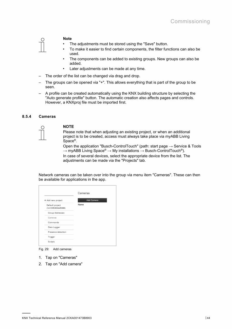
Network cameras can be taken over into the group via menu item "Cameras". These can then be available for applications in the app.
Fig. 29: Add cameras
1. Tap on "Cameras"
2. Tap on "Add camera"
Commissioning
KNX Technical Reference Manual 2CKA001473B8903 │45
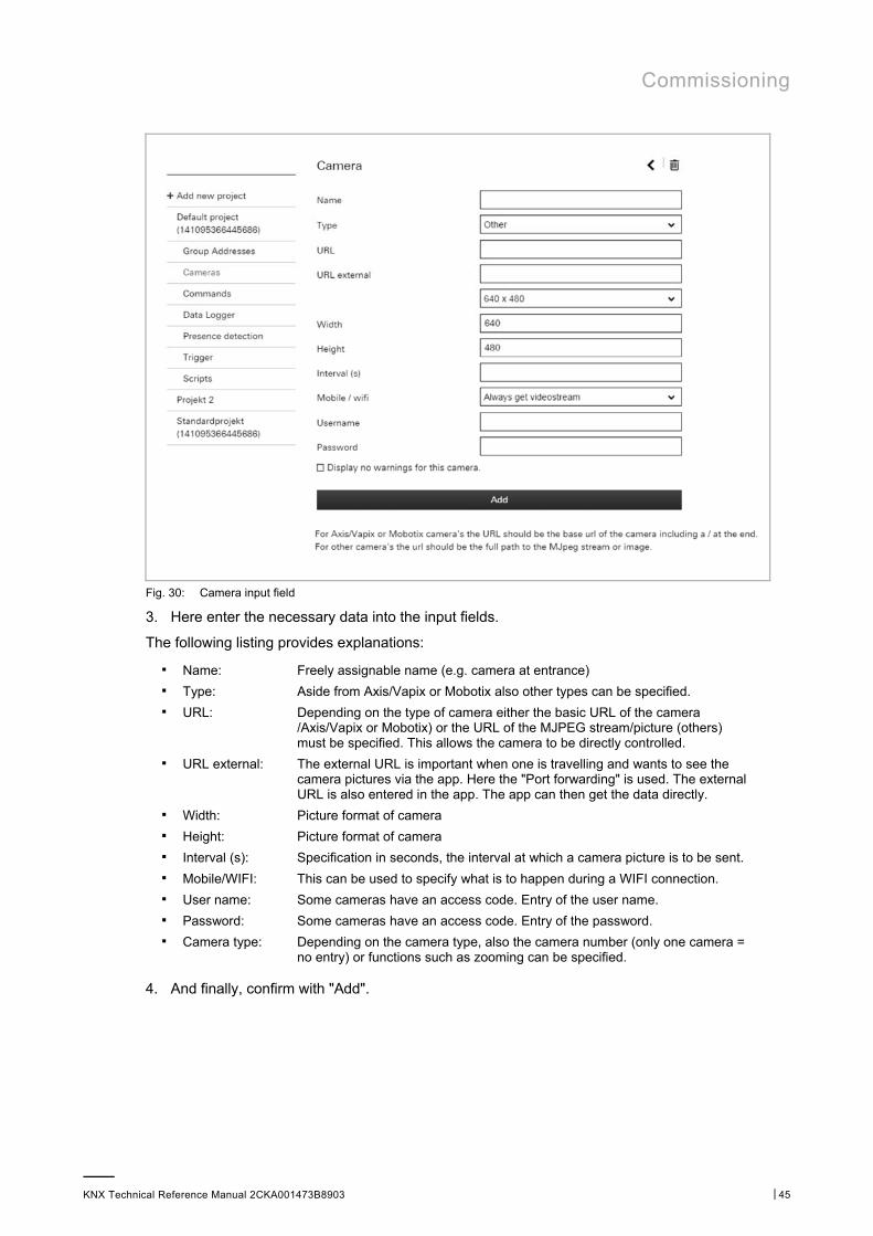
Fig. 30: Camera input field
3. Here enter the necessary data into the input fields.
The following listing provides explanations:
■ Name: Freely assignable name (e.g. camera at entrance) ■ Type: Aside from Axis/Vapix or Mobotix also other types can be specified. ■ URL: Depending on the type of camera either the basic URL of the camera
/Axis/Vapix or Mobotix) or the URL of the MJPEG stream/picture (others) must be specified. This allows the camera to be directly controlled.
■ URL external: The external URL is important when one is travelling and wants to see the camera pictures via the app. Here the "Port forwarding" is used. The external URL is also entered in the app. The app can then get the data directly.
■ Width: Picture format of camera ■ Height: Picture format of camera ■ Interval (s): Specification in seconds, the interval at which a camera picture is to be sent. ■ Mobile/WIFI: This can be used to specify what is to happen during a WIFI connection. ■ User name: Some cameras have an access code. Entry of the user name. ■ Password: Some cameras have an access code. Entry of the password. ■ Camera type: Depending on the camera type, also the camera number (only one camera =
no entry) or functions such as zooming can be specified.
4. And finally, confirm with "Add".
Commissioning
KNX Technical Reference Manual 2CKA001473B8903 │46
The camera is taken up in the list of available cameras.
NOTE Later adjustments can be made at any time: ■ Adjusting data:
Tap in the list on the editing icon next to the camera. The editing page opens. And finally, press the "Add" button.
■ Deleting: Tap in the list on the editing icon next to the camera. The editing page opens. Click on the rubbish bin icon.
To find cameras easier in the list, also the filter functions can be used.
The cameras can be added to existing groups. Also new groups can be added.
8.5.5 Commands
NOTE Please note that when adjusting an existing project, or when an additional project is to be created, access must always take place via myABB Living Space®. Open the application "Busch-ControlTouch" (path: start page → Service & Tools → myABB Living Space® → My installations → Busch-ControlTouch®). In case of several devices, select the appropriate device from the list. The adjustments can be made via the "Projects" tab.
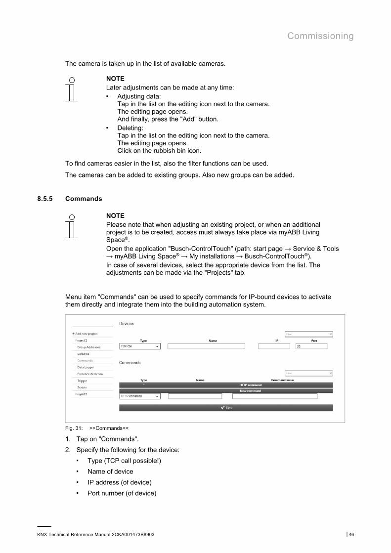
Menu item "Commands" can be used to specify commands for IP-bound devices to activate them directly and integrate them into the building automation system.
Fig. 31: >>Commands<<
1. Tap on "Commands".
2. Specify the following for the device: ■ Type (TCP call possible!)
■ Name of device
■ IP address (of device)
■ Port number (of device)
Commissioning
KNX Technical Reference Manual 2CKA001473B8903 │47
NOTE This entry must be confirmed with "Save".
3. Tap on the "Save" button.
4. Create a new HTTP command.
5. Then select the command type.
6. Enter also a name for the command type (for later allocation) and the command value (hexadecimal value).
7. And finally, tap on the "Save" button.
The TCP call can now be used for the "Trigger" function.
8.5.6 Data logger
NOTE Please note that when adjusting an existing project, or when an additional project is to be created, access must always take place via myABB Living Space®. Open the application "Busch-ControlTouch" (path: start page → Service & Tools → myABB Living Space® → My installations → Busch-ControlTouch®). In case of several devices, select the appropriate device from the list. The adjustments can be made via the "Projects" tab.
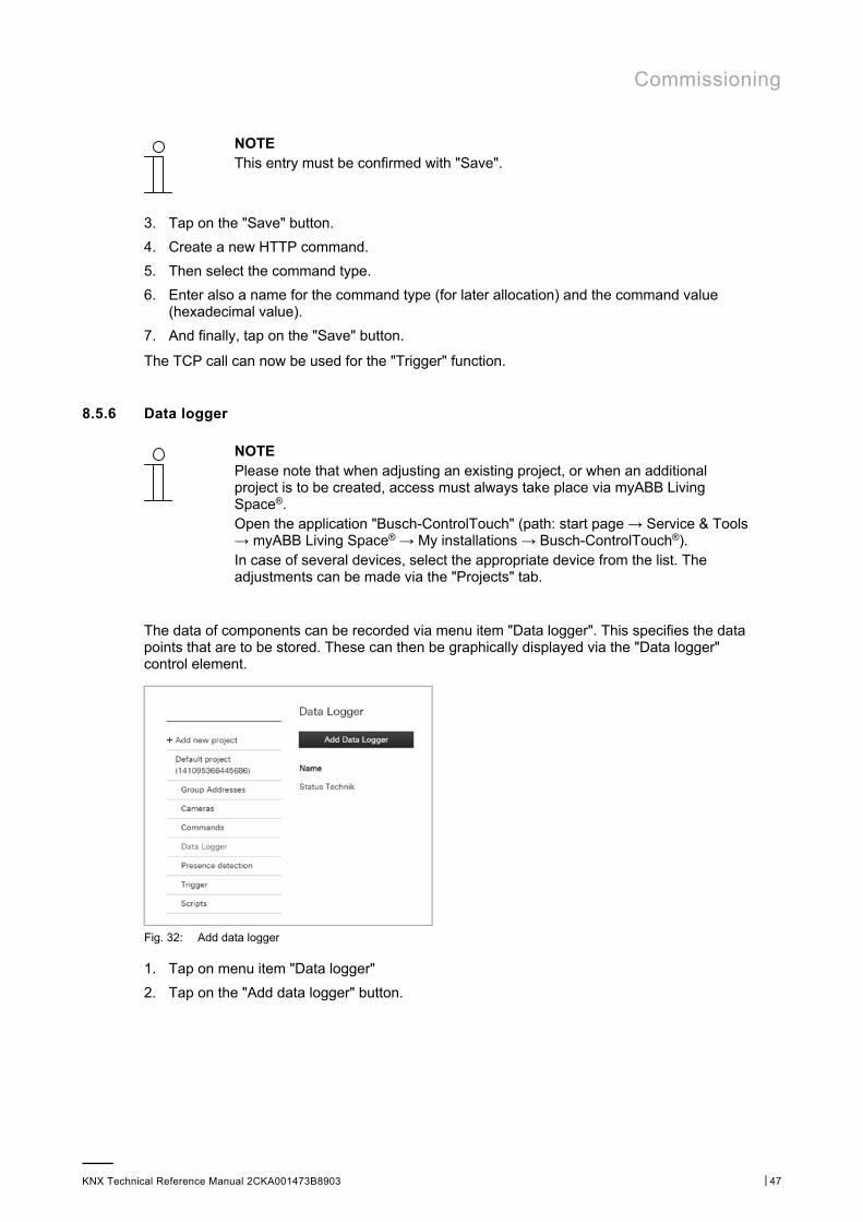
The data of components can be recorded via menu item "Data logger". This specifies the data points that are to be stored. These can then be graphically displayed via the "Data logger" control element.
Fig. 32: Add data logger
1. Tap on menu item "Data logger"
2. Tap on the "Add data logger" button.
Commissioning
KNX Technical Reference Manual 2CKA001473B8903 │48
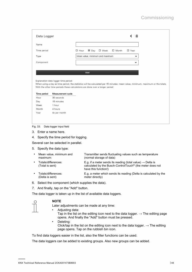
Fig. 33: Data logger input field
3. Enter a name here.
4. Specify the time period for logging.
Several can be selected in parallel.
5. Specify the data type:
■ Mean value, minimum and maximum:
Transmitter sends fluctuating values such as temperature (normal storage of data)
■ Totals/differences: (Total is sent)
E.g. if a meter sends its reading (total value) → Delta is calculated by the Busch-ControlTouch® (the meter does not have this function!)
■ Totals/differences: (Delta is sent)
E.g. a meter which sends its reading (Delta is calculated by the meter directly)
6. Select the component (which supplies the data).
7. And finally, tap on the "Add" button.
The data logger is taken up in the list of available data loggers.
NOTE Later adjustments can be made at any time: ■ Adjusting data:
Tap in the list on the editing icon next to the data logger. → The editing page opens. And finally the "Add" button must be pressed.
■ Deleting: Click/tap in the list on the editing icon next to the data logger. → The editing page opens. Tap on the rubbish bin icon.
To find data loggers easier in the list, also the filter functions can be used.
The data loggers can be added to existing groups. Also new groups can be added.
Commissioning
KNX Technical Reference Manual 2CKA001473B8903 │49
8.5.7 Presence detection
NOTE Please note that when adjusting an existing project, or when an additional project is to be created, access must always take place via myABB Living Space®. Open the application "Busch-ControlTouch" (path: start page → Service & Tools → myABB Living Space® → My installations → Busch-ControlTouch®). In case of several devices, select the appropriate device from the list. The adjustments can be made via the "Projects" tab.
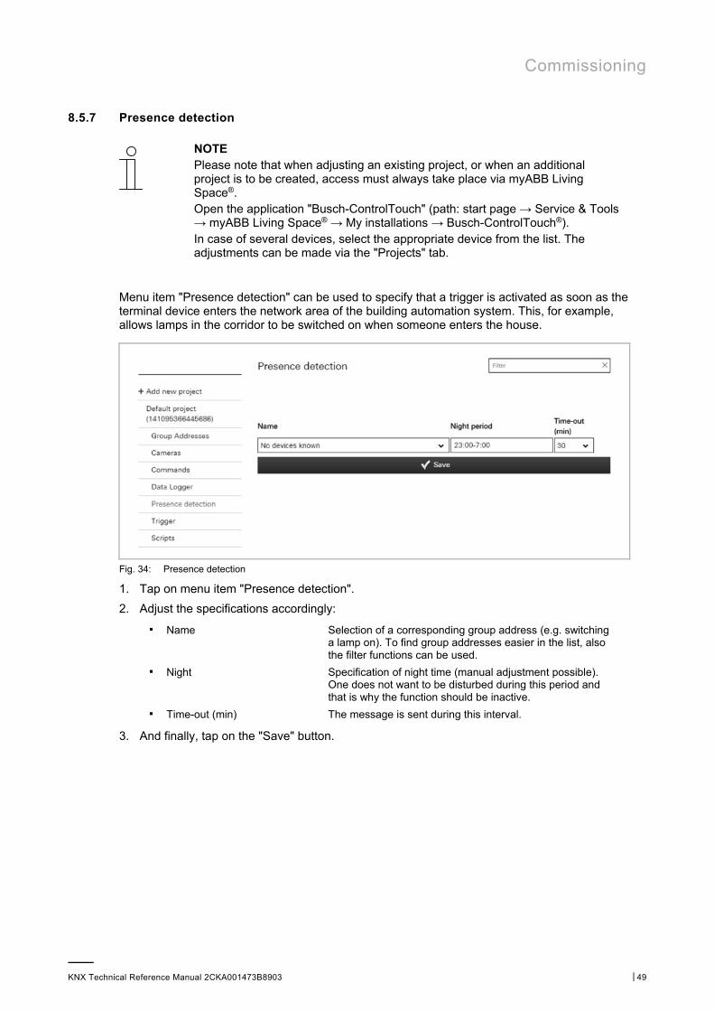
Menu item "Presence detection" can be used to specify that a trigger is activated as soon as the terminal device enters the network area of the building automation system. This, for example, allows lamps in the corridor to be switched on when someone enters the house.
Fig. 34: Presence detection
1. Tap on menu item "Presence detection".
2. Adjust the specifications accordingly:
■ Name Selection of a corresponding group address (e.g. switching a lamp on). To find group addresses easier in the list, also the filter functions can be used.
■ Night Specification of night time (manual adjustment possible). One does not want to be disturbed during this period and that is why the function should be inactive.
■ Time-out (min) The message is sent during this interval.
3. And finally, tap on the "Save" button.
Commissioning
KNX Technical Reference Manual 2CKA001473B8903 │50
The presence detection is, among others, taken up in the list of available presence detectors for the alarms or triggers.
NOTE Later adjustments can be made at any time: ■ Adjusting data:
Adjust the data by either selecting a different group address or adjusting the time specifications. And finally the "Save" button must be pressed.
■ Deleting: Delete the entry for the group addresses under "Name". And finally the "Save" button must be pressed.
To find group addresses easier in the list, also the filter functions can be used.
8.5.8 Triggers
NOTE Please note that when adjusting an existing project, or when an additional project is to be created, access must always take place via myABB Living Space®. Open the application "Busch-ControlTouch" (path: start page → Service & Tools → myABB Living Space® → My installations → Busch-ControlTouch®). In case of several devices, select the appropriate device from the list. The adjustments can be made via the "Projects" tab.
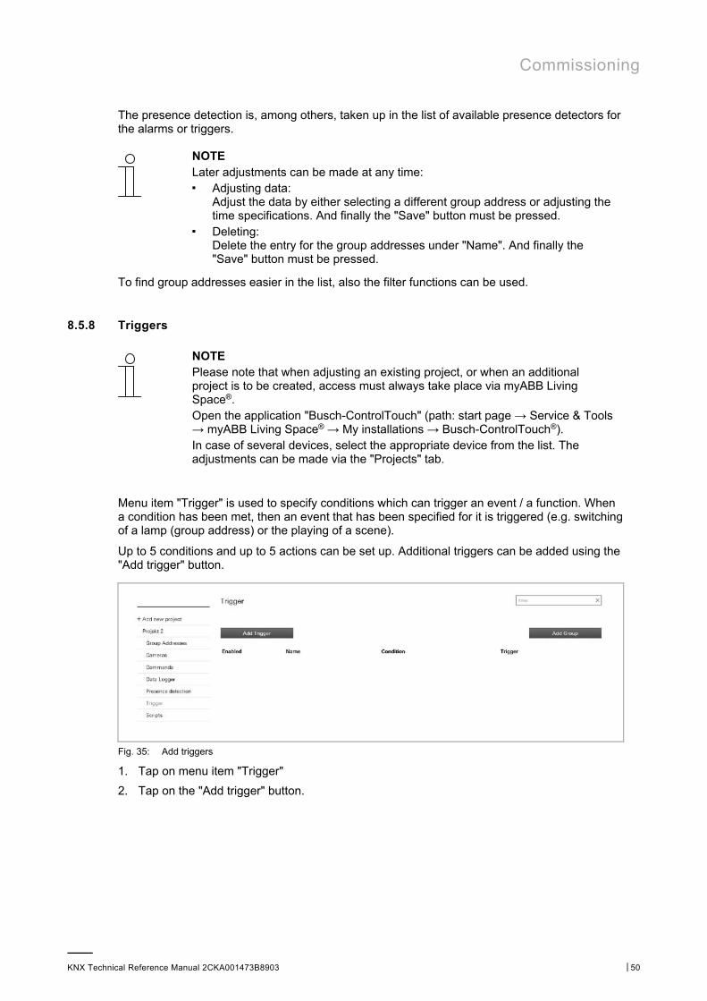
Menu item "Trigger" is used to specify conditions which can trigger an event / a function. When a condition has been met, then an event that has been specified for it is triggered (e.g. switching of a lamp (group address) or the playing of a scene).
Up to 5 conditions and up to 5 actions can be set up. Additional triggers can be added using the "Add trigger" button.
Fig. 35: Add triggers
1. Tap on menu item "Trigger"
2. Tap on the "Add trigger" button.

Commissioning
KNX Technical Reference Manual 2CKA001473B8903 │51
Fig. 36: Trigger input field
Each trigger function can be activated and deactivated.
This function can also be executed in the overview list by clicking the name.
3. Enter a name.
4. Specify with "Condition" which one is to trigger a triggering function.
Conditions based on a group address can either be a triggering condition or a condition which is validated when triggering another condition. The type of condition can be modified by clicking the icon to the left of each condition.
Note Conditions such as the HTTP trigger are always triggering conditions.
When using more than one condition, AND or OR can be used to compare the different conditions in the validation. Click AND/OR in order to switch between the two options.
You can use parentheses either side of the conditions for more complex functions by clicking to the left or right of a condition. You can then remove parentheses by right-clicking on them. The number of relative parentheses is validated.
Actions are always executed in the order in which they were added. A "WAIT" action can therefore be used to pause between the execution of an action.
In order to make the trigger available on the device, the project must be loaded to the device. The triggers are displayed on the device in the "Alarm messages" page. Here you can deactivate and activate triggers. In addition, a simulation can be performed in order to verify the actions being executed.
If the "Actions" option was activated in the user logs, the log file shows the validation of the triggers and whether the corresponding actions have been executed correctly.
The following conditions can be selected (depending on the type of condition, additional settings are possible to further vary the condition):
■ Group address (specifying a group address which triggers an event/function)
■ HTTP trigger
■ Protocol connected/disconnected (connection or disconnection with KNX protocol) ■ Trigger of presence detection (trigger for message when terminal device is again in the
home network)
5. Use "Actions" to specify which event/function is to be triggered when the condition has been met.
Commissioning
KNX Technical Reference Manual 2CKA001473B8903 │52
The following trigger functions can be selected (depending on the type of trigger, additional settings are possible to further vary the trigger function):
■ Group address (specifying a group address, which is triggered)
■ Call-up of scene
■ Script (call-up of a specified script. This must be created beforehand)
■ Command (call-up of a specified command. This must be created beforehand)
■ Presence simulation
■ Waiting
6. And finally, tap on the "Ready" button.
The trigger function is taken up in the list of available trigger functions.
Note Later adjustments can be made at any time: ■ Adjusting data:
Tap in the list on the editing icon next to the trigger function. → The editing page opens. And finally the "Ready" button must be pressed.
■ Deleting: Tap in the list on the editing icon next to the trigger function. → The editing page opens. Tap on the rubbish bin icon.
To find trigger functions easier in the list, the filter functions can also be used.
The trigger functions can be added to existing groups. New groups can also be added.
8.5.9 Scripts
NOTE Please note that when adjusting an existing project, or when an additional project is to be created, access must always take place via myABB Living Space®. Open the application "Busch-ControlTouch" (path: start page → Service & Tools → myABB Living Space® → My installations → Busch-ControlTouch®). In case of several devices, select the appropriate device from the list. The adjustments can be made via the "Projects" tab.
Menu item "Scripts" can be used to write one's own small programs (scripts) which can be used in the Busch-ControlTouch®. These scripts are very flexible and can be used to add numerous additional functions to a building automation system. Logic functions, delay actions (triggers), scenes with RGB sequences and much more can be created. Scripts can be triggered by a scene, a time program, an action (trigger) or another script.
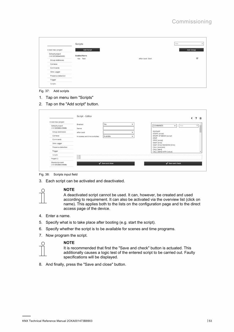
Commissioning
KNX Technical Reference Manual 2CKA001473B8903 │53
Fig. 37: Add scripts
1. Tap on menu item "Scripts"
2. Tap on the "Add script" button.
Fig. 38: Scripts input field
3. Each script can be activated and deactivated.
NOTE A deactivated script cannot be used. It can, however, be created and used according to requirement. It can also be activated via the overview list (click on name). This applies both to the lists on the configuration page and to the direct access page of the device.
4. Enter a name.
5. Specify what is to take place after booting (e.g. start the script).
6. Specify whether the script is to be available for scenes and time programs.
7. Now program the script.
NOTE It is recommended that first the "Save and check" button is actuated. This additionally causes a logic test of the entered script to be carried out. Faulty specifications will be displayed.
8. And finally, press the "Save and close" button.
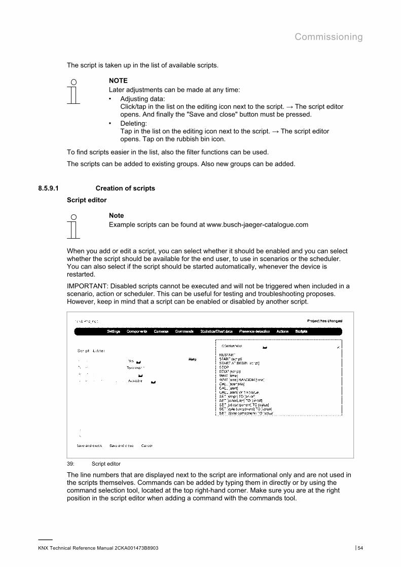
Commissioning
KNX Technical Reference Manual 2CKA001473B8903 │54
The script is taken up in the list of available scripts.
NOTE Later adjustments can be made at any time: ■ Adjusting data:
Click/tap in the list on the editing icon next to the script. → The script editor opens. And finally the "Save and close" button must be pressed.
■ Deleting: Tap in the list on the editing icon next to the script. → The script editor opens. Tap on the rubbish bin icon.
To find scripts easier in the list, also the filter functions can be used.
The scripts can be added to existing groups. Also new groups can be added.
8.5.9.1 Creation of scripts
Script editor
Note Example scripts can be found at www.busch-jaeger-catalogue.com
When you add or edit a script, you can select whether it should be enabled and you can select whether the script should be available for the end user, to use in scenarios or the scheduler. You can also select if the script should be started automatically, whenever the device is restarted.
IMPORTANT: Disabled scripts cannot be executed and will not be triggered when included in a scenario, action or scheduler. This can be useful for testing and troubleshooting proposes. However, keep in mind that a script can be enabled or disabled by another script.
39: Script editor
The line numbers that are displayed next to the script are informational only and are not used in the scripts themselves. Commands can be added by typing them in directly or by using the command selection tool, located at the top right-hand corner. Make sure you are at the right position in the script editor when adding a command with the commands tool.
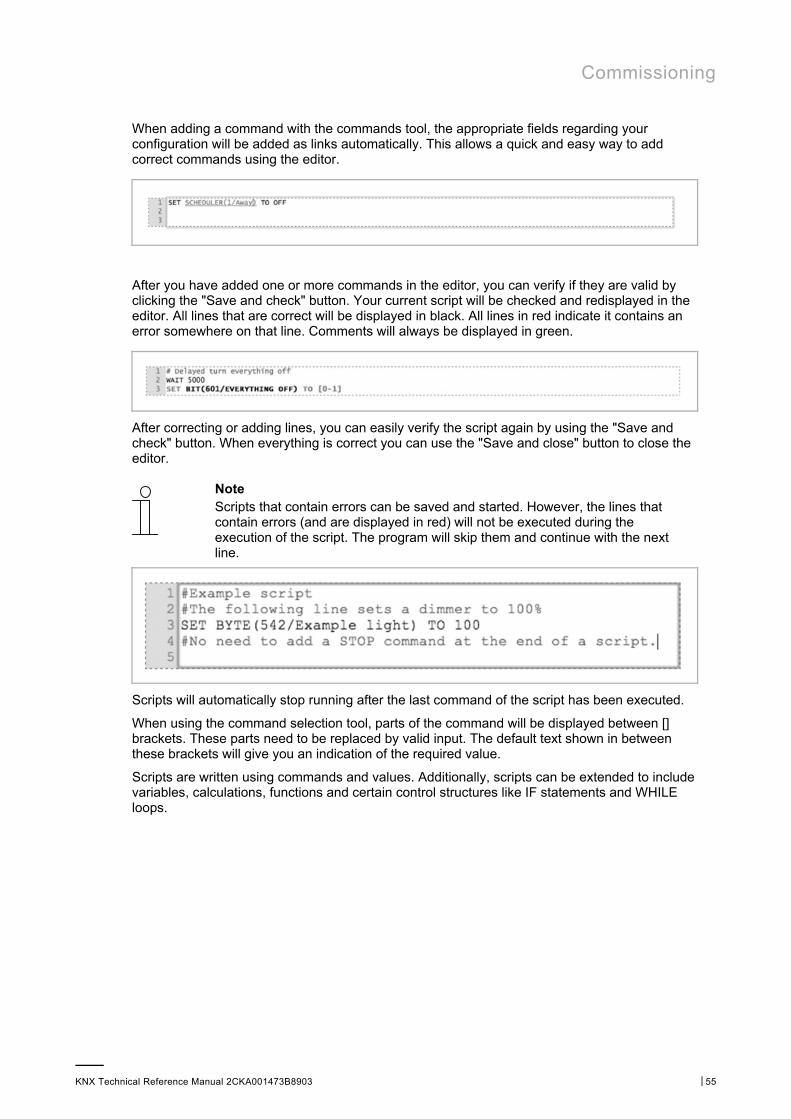
Commissioning
KNX Technical Reference Manual 2CKA001473B8903 │55
When adding a command with the commands tool, the appropriate fields regarding your configuration will be added as links automatically. This allows a quick and easy way to add correct commands using the editor.
After you have added one or more commands in the editor, you can verify if they are valid by clicking the "Save and check" button. Your current script will be checked and redisplayed in the editor. All lines that are correct will be displayed in black. All lines in red indicate it contains an error somewhere on that line. Comments will always be displayed in green.
After correcting or adding lines, you can easily verify the script again by using the "Save and check" button. When everything is correct you can use the "Save and close" button to close the editor.
Note Scripts that contain errors can be saved and started. However, the lines that contain errors (and are displayed in red) will not be executed during the execution of the script. The program will skip them and continue with the next line.
Scripts will automatically stop running after the last command of the script has been executed.
When using the command selection tool, parts of the command will be displayed between [] brackets. These parts need to be replaced by valid input. The default text shown in between these brackets will give you an indication of the required value.
Scripts are written using commands and values. Additionally, scripts can be extended to include variables, calculations, functions and certain control structures like IF statements and WHILE loops.
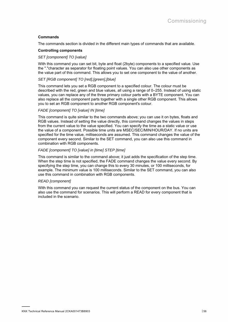
Commissioning
KNX Technical Reference Manual 2CKA001473B8903 │56
Commands
The commands section is divided in the different main types of commands that are available.
Controlling components
SET [component] TO [value]
With this command you can set bit, byte and float (2byte) components to a specified value. Use the "."character as separator for floating point values. You can also use other components as the value part of this command. This allows you to set one component to the value of another.
SET [RGB component] TO [red],[green],[blue]
This command lets you set a RGB component to a specified colour. The colour must be described with the red, green and blue values, all using a range of 0–255. Instead of using static values, you can replace any of the three primary colour parts with a BYTE component. You can also replace all the component parts together with a single other RGB component. This allows you to set an RGB component to another RGB component's colour.
FADE [component] TO [value] IN [time]
This command is quite similar to the two commands above; you can use it on bytes, floats and RGB values. Instead of setting the value directly, this command changes the values in steps from the current value to the value specified. You can specify the time as a static value or use the value of a component. Possible time units are MSEC/SEC/MIN/HOUR/DAY. If no units are specified for the time value, milliseconds are assumed. This command changes the value of the component every second. Similar to the SET command, you can also use this command in combination with RGB components.
FADE [component] TO [value] in [time] STEP [time]
This command is similar to the command above; it just adds the specification of the step time. When the step time is not specified, the FADE command changes the value every second. By specifying the step time, you can change this to every 30 minutes, or 100 milliseconds, for example. The minimum value is 100 milliseconds. Similar to the SET command, you can also use this command in combination with RGB components.
READ [component]
With this command you can request the current status of the component on the bus. You can also use the command for scenarios. This will perform a READ for every component that is included in the scenario.
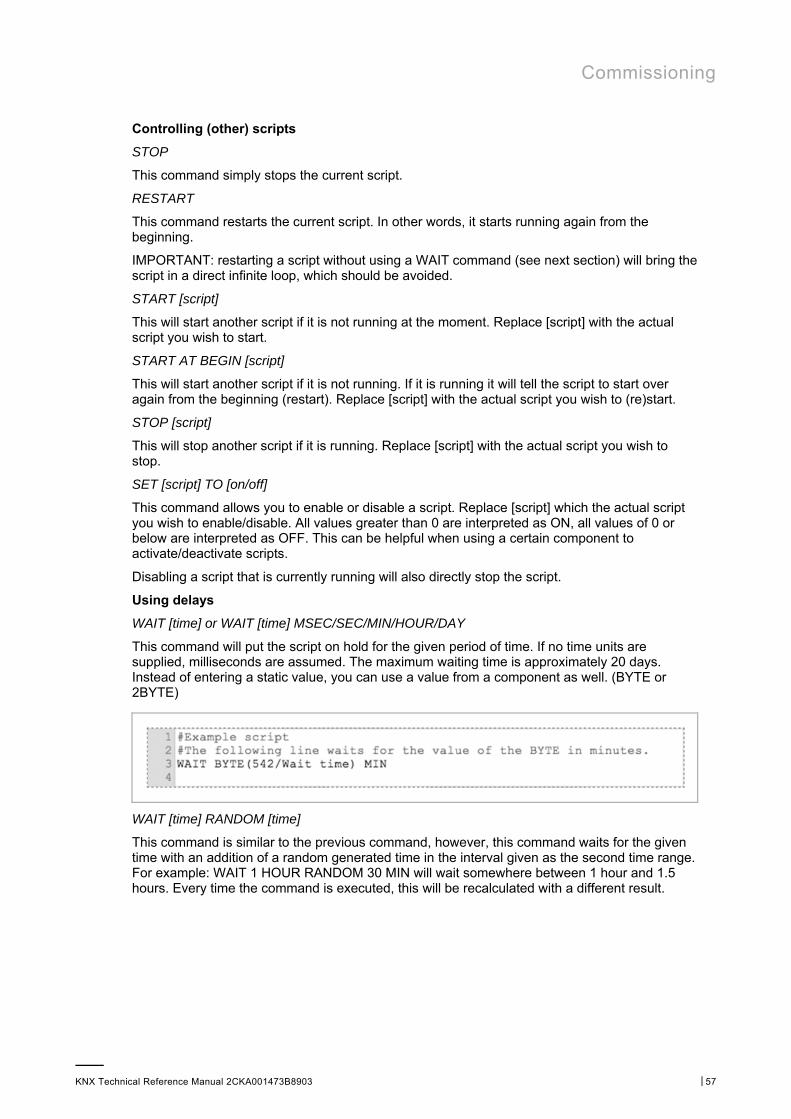
Commissioning
KNX Technical Reference Manual 2CKA001473B8903 │57
Controlling (other) scripts
STOP
This command simply stops the current script.
RESTART
This command restarts the current script. In other words, it starts running again from the beginning.
IMPORTANT: restarting a script without using a WAIT command (see next section) will bring the script in a direct infinite loop, which should be avoided.
START [script]
This will start another script if it is not running at the moment. Replace [script] with the actual script you wish to start.
START AT BEGIN [script]
This will start another script if it is not running. If it is running it will tell the script to start over again from the beginning (restart). Replace [script] with the actual script you wish to (re)start.
STOP [script]
This will stop another script if it is running. Replace [script] with the actual script you wish to stop.
SET [script] TO [on/off]
This command allows you to enable or disable a script. Replace [script] which the actual script you wish to enable/disable. All values greater than 0 are interpreted as ON, all values of 0 or below are interpreted as OFF. This can be helpful when using a certain component to activate/deactivate scripts.
Disabling a script that is currently running will also directly stop the script.
Using delays
WAIT [time] or WAIT [time] MSEC/SEC/MIN/HOUR/DAY
This command will put the script on hold for the given period of time. If no time units are supplied, milliseconds are assumed. The maximum waiting time is approximately 20 days. Instead of entering a static value, you can use a value from a component as well. (BYTE or 2BYTE)
WAIT [time] RANDOM [time]
This command is similar to the previous command, however, this command waits for the given time with an addition of a random generated time in the interval given as the second time range. For example: WAIT 1 HOUR RANDOM 30 MIN will wait somewhere between 1 hour and 1.5 hours. Every time the command is executed, this will be recalculated with a different result.
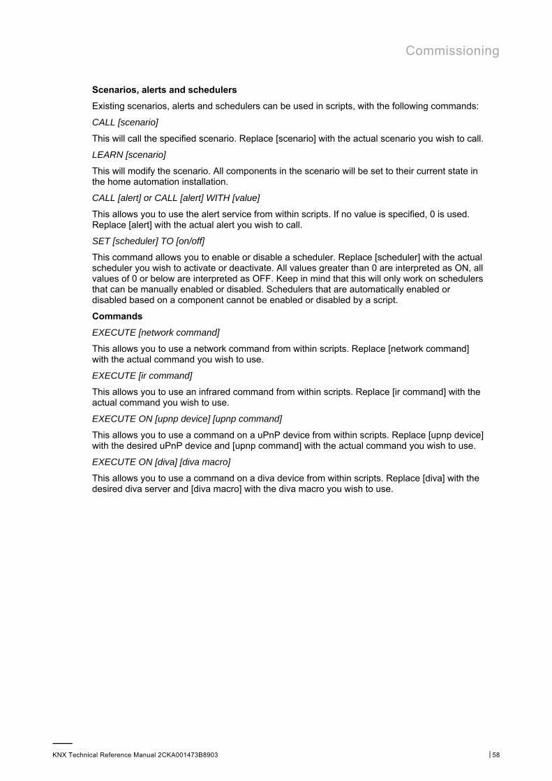
Commissioning
KNX Technical Reference Manual 2CKA001473B8903 │58
Scenarios, alerts and schedulers
Existing scenarios, alerts and schedulers can be used in scripts, with the following commands:
CALL [scenario]
This will call the specified scenario. Replace [scenario] with the actual scenario you wish to call.
LEARN [scenario]
This will modify the scenario. All components in the scenario will be set to their current state in the home automation installation.
CALL [alert] or CALL [alert] WITH [value]
This allows you to use the alert service from within scripts. If no value is specified, 0 is used. Replace [alert] with the actual alert you wish to call.
SET [scheduler] TO [on/off]
This command allows you to enable or disable a scheduler. Replace [scheduler] with the actual scheduler you wish to activate or deactivate. All values greater than 0 are interpreted as ON, all values of 0 or below are interpreted as OFF. Keep in mind that this will only work on schedulers that can be manually enabled or disabled. Schedulers that are automatically enabled or disabled based on a component cannot be enabled or disabled by a script.
Commands
EXECUTE [network command]
This allows you to use a network command from within scripts. Replace [network command] with the actual command you wish to use.
EXECUTE [ir command]
This allows you to use an infrared command from within scripts. Replace [ir command] with the actual command you wish to use.
EXECUTE ON [upnp device] [upnp command]
This allows you to use a command on a uPnP device from within scripts. Replace [upnp device] with the desired uPnP device and [upnp command] with the actual command you wish to use.
EXECUTE ON [diva] [diva macro]
This allows you to use a command on a diva device from within scripts. Replace [diva] with the desired diva server and [diva macro] with the diva macro you wish to use.
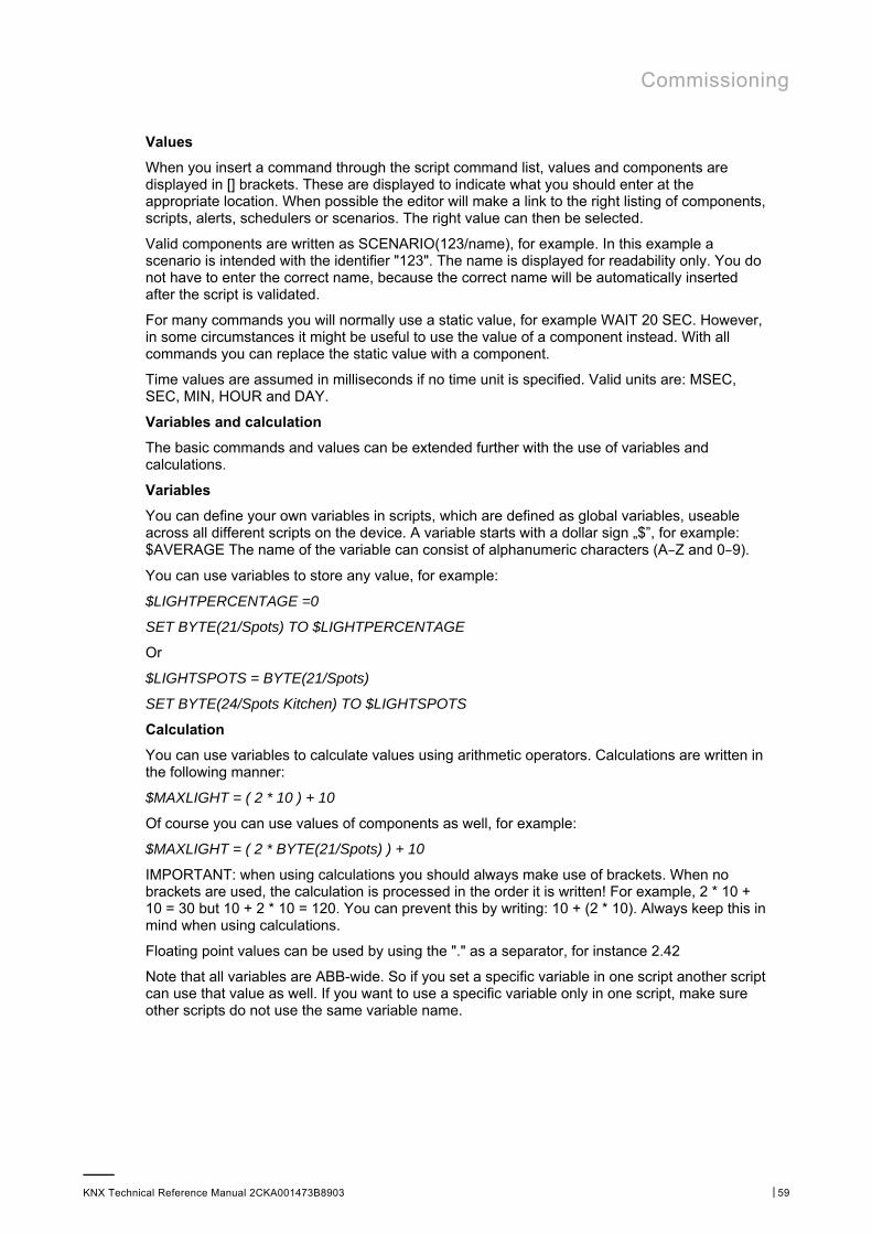
Commissioning
KNX Technical Reference Manual 2CKA001473B8903 │59
Values
When you insert a command through the script command list, values and components are displayed in [] brackets. These are displayed to indicate what you should enter at the appropriate location. When possible the editor will make a link to the right listing of components, scripts, alerts, schedulers or scenarios. The right value can then be selected.
Valid components are written as SCENARIO(123/name), for example. In this example a scenario is intended with the identifier "123". The name is displayed for readability only. You do not have to enter the correct name, because the correct name will be automatically inserted after the script is validated.
For many commands you will normally use a static value, for example WAIT 20 SEC. However, in some circumstances it might be useful to use the value of a component instead. With all commands you can replace the static value with a component.
Time values are assumed in milliseconds if no time unit is specified. Valid units are: MSEC, SEC, MIN, HOUR and DAY.
Variables and calculation
The basic commands and values can be extended further with the use of variables and calculations.
Variables
You can define your own variables in scripts, which are defined as global variables, useable across all different scripts on the device. A variable starts with a dollar sign „$”, for example: $AVERAGE The name of the variable can consist of alphanumeric characters (A–Z and 0–9).
You can use variables to store any value, for example:
$LIGHTPERCENTAGE =0
SET BYTE(21/Spots) TO $LIGHTPERCENTAGE
Or
$LIGHTSPOTS = BYTE(21/Spots)
SET BYTE(24/Spots Kitchen) TO $LIGHTSPOTS
Calculation
You can use variables to calculate values using arithmetic operators. Calculations are written in the following manner:
$MAXLIGHT = ( 2 * 10 ) + 10
Of course you can use values of components as well, for example:
$MAXLIGHT = ( 2 * BYTE(21/Spots) ) + 10
IMPORTANT: when using calculations you should always make use of brackets. When no brackets are used, the calculation is processed in the order it is written! For example, 2 * 10 + 10 = 30 but 10 + 2 * 10 = 120. You can prevent this by writing: 10 + (2 * 10). Always keep this in mind when using calculations.
Floating point values can be used by using the "." as a separator, for instance 2.42
Note that all variables are ABB-wide. So if you set a specific variable in one script another script can use that value as well. If you want to use a specific variable only in one script, make sure other scripts do not use the same variable name.
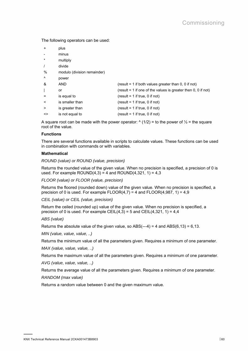
Commissioning
KNX Technical Reference Manual 2CKA001473B8903 │60
The following operators can be used:
+ plus
- minus
* multiply
/ divide
% modulo (division remainder)
^ power
& AND (result = 1 if both values greater than 0, 0 if not)
| or (result = 1 if one of the values is greater then 0, 0 if not)
= is equal to (result = 1 if true, 0 if not)
< is smaller than (result = 1 if true, 0 if not)
> is greater than (result = 1 if true, 0 if not)
<> is not equal to (result = 1 if true, 0 if not)
A square root can be made with the power operator: ^ (1/2) = to the power of ½ = the square root of the value.
Functions
There are several functions available in scripts to calculate values. These functions can be used in combination with commands or with variables.
Mathematical
ROUND (value) or ROUND (value, precision)
Returns the rounded value of the given value. When no precision is specified, a precision of 0 is used. For example ROUND(4,3) = 4 and ROUND(4,321, 1) = 4,3
FLOOR (value) or FLOOR (value, precision)
Returns the floored (rounded down) value of the given value. When no precision is specified, a precision of 0 is used. For example FLOOR(4,7) = 4 and FLOOR(4,987, 1) = 4,9
CEIL (value) or CEIL (value, precision)
Return the ceiled (rounded up) value of the given value. When no precision is specified, a precision of 0 is used. For example CEIL(4,3) = 5 and CEIL(4,321, 1) = 4,4
ABS (value)
Returns the absolute value of the given value, so ABS(--‐4) = 4 and ABS(6,13) = 6,13.
MIN (value, value, value, ..)
Returns the minimum value of all the parameters given. Requires a minimum of one parameter.
MAX (value, value, value, ..)
Returns the maximum value of all the parameters given. Requires a minimum of one parameter.
AVG (value, value, value, ..)
Returns the average value of all the parameters given. Requires a minimum of one parameter.
RANDOM (max value)
Returns a random value between 0 and the given maximum value.
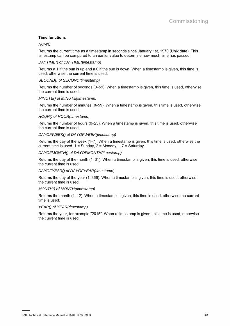
Commissioning
KNX Technical Reference Manual 2CKA001473B8903 │61
Time functions
NOW()
Returns the current time as a timestamp in seconds since January 1st, 1970 (Unix date). This timestamp can be compared to an earlier value to determine how much time has passed.
DAYTIME() of DAYTIME(timestamp)
Returns a 1 if the sun is up and a 0 if the sun is down. When a timestamp is given, this time is used, otherwise the current time is used.
SECOND() of SECOND(timestamp)
Returns the number of seconds (0–59). When a timestamp is given, this time is used, otherwise the current time is used.
MINUTE() of MINUTE(timestamp)
Returns the number of minutes (0–59). When a timestamp is given, this time is used, otherwise the current time is used.
HOUR() of HOUR(timestamp)
Returns the number of hours (0–23). When a timestamp is given, this time is used, otherwise the current time is used.
DAYOFWEEK() of DAYOFWEEK(timestamp)
Returns the day of the week (1–7). When a timestamp is given, this time is used, otherwise the current time is used. 1 = Sunday, 2 = Monday, .. 7 = Saturday.
DAYOFMONTH() of DAYOFMONTH(timestamp)
Returns the day of the month (1–31). When a timestamp is given, this time is used, otherwise the current time is used.
DAYOFYEAR() of DAYOFYEAR(timestamp)
Returns the day of the year (1–366). When a timestamp is given, this time is used, otherwise the current time is used.
MONTH() of MONTH(timestamp)
Returns the month (1–12). When a timestamp is given, this time is used, otherwise the current time is used.
YEAR() of YEAR(timestamp)
Returns the year, for example "2015". When a timestamp is given, this time is used, otherwise the current time is used.
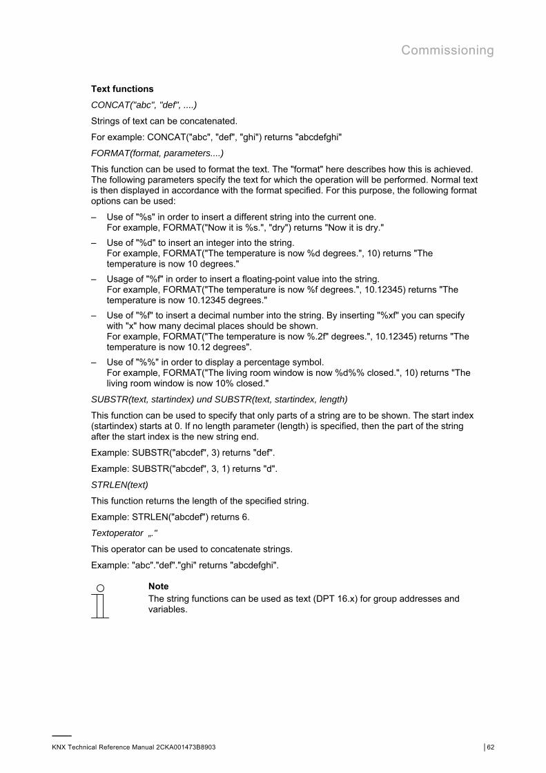
Commissioning
KNX Technical Reference Manual 2CKA001473B8903 │62
Text functions
CONCAT("abc", "def", ....)
Strings of text can be concatenated.
For example: CONCAT("abc", "def", "ghi") returns "abcdefghi"
FORMAT(format, parameters....)
This function can be used to format the text. The "format" here describes how this is achieved. The following parameters specify the text for which the operation will be performed. Normal text is then displayed in accordance with the format specified. For this purpose, the following format options can be used:
– Use of "%s" in order to insert a different string into the current one. For example, FORMAT("Now it is %s.", "dry") returns "Now it is dry."
– Use of "%d" to insert an integer into the string. For example, FORMAT("The temperature is now %d degrees.", 10) returns "The temperature is now 10 degrees."
– Usage of "%f" in order to insert a floating-point value into the string. For example, FORMAT("The temperature is now %f degrees.", 10.12345) returns "The temperature is now 10.12345 degrees."
– Use of "%f" to insert a decimal number into the string. By inserting "%xf" you can specify with "x" how many decimal places should be shown. For example, FORMAT("The temperature is now %.2f" degrees.", 10.12345) returns "The temperature is now 10.12 degrees".
– Use of "%%" in order to display a percentage symbol. For example, FORMAT("The living room window is now %d%% closed.", 10) returns "The living room window is now 10% closed."
SUBSTR(text, startindex) und SUBSTR(text, startindex, length)
This function can be used to specify that only parts of a string are to be shown. The start index (startindex) starts at 0. If no length parameter (length) is specified, then the part of the string after the start index is the new string end.
Example: SUBSTR("abcdef", 3) returns "def".
Example: SUBSTR("abcdef", 3, 1) returns "d".
STRLEN(text)
This function returns the length of the specified string.
Example: STRLEN("abcdef") returns 6.
Textoperator „."
This operator can be used to concatenate strings.
Example: "abc"."def"."ghi" returns "abcdefghi".
Note The string functions can be used as text (DPT 16.x) for group addresses and variables.
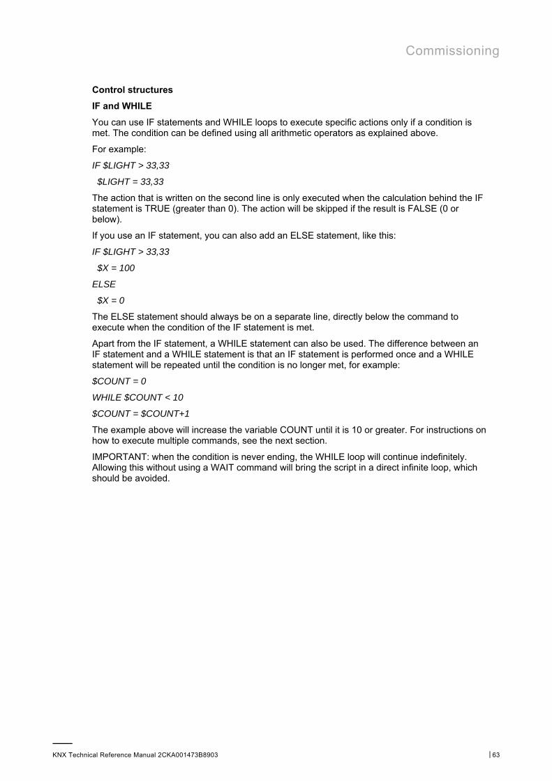
Commissioning
KNX Technical Reference Manual 2CKA001473B8903 │63
Control structures
IF and WHILE
You can use IF statements and WHILE loops to execute specific actions only if a condition is met. The condition can be defined using all arithmetic operators as explained above.
For example:
IF $LIGHT > 33,33
$LIGHT = 33,33
The action that is written on the second line is only executed when the calculation behind the IF statement is TRUE (greater than 0). The action will be skipped if the result is FALSE (0 or below).
If you use an IF statement, you can also add an ELSE statement, like this:
IF $LIGHT > 33,33
$X = 100
ELSE
$X = 0
The ELSE statement should always be on a separate line, directly below the command to execute when the condition of the IF statement is met.
Apart from the IF statement, a WHILE statement can also be used. The difference between an IF statement and a WHILE statement is that an IF statement is performed once and a WHILE statement will be repeated until the condition is no longer met, for example:
$COUNT = 0
WHILE $COUNT < 10
$COUNT = $COUNT+1
The example above will increase the variable COUNT until it is 10 or greater. For instructions on how to execute multiple commands, see the next section.
IMPORTANT: when the condition is never ending, the WHILE loop will continue indefinitely. Allowing this without using a WAIT command will bring the script in a direct infinite loop, which should be avoided.

Commissioning
KNX Technical Reference Manual 2CKA001473B8903 │64
BEGIN and END
If you need to execute more than one command after a IF, WHILE or ELSE statement, you can use BEGIN and END statements.
These should be written on separate lines as well, for example:
$X = 0
WHILE $X < 11
BEGIN
$Y = $X * 10
SET BYTE(22/EXAMPLE BYTE) TO $Y
$X = $X + 1
END
Another example:
IF $LIGHT > 33,33
BEGIN
$X = 100
$Y = 0
END
ELSE
BEGIN
$X = 0
$Y = 100
END
Other
SEND WAKEONLAN TO [ma:c :ad:re:ss]
With this command you can send a wake on lan command to a network device. Replace [ma:c :ad:re:ss] with the MAC address of the intended device.
OPEN KNXTUNNEL
With this command you can enable the KNX tunnel access on the device for programming with ETS for a period of 8 hours.
CLOSE KNXTUNNEL
With this command you can disable the KNX tunnel access on the device for programming with ETS.
Using all described commands, values, functions and control structures will allow you to create almost any functionality required.
Commissioning
KNX Technical Reference Manual 2CKA001473B8903 │65
8.5.10 Assigning a project to a device
Several projects can be created. However, only one project can be used in the one device. This means that one project is to be assigned to a device. This is carried out via the "Project in device" function. All available projects can be selected from the options list. Access is gained via myABB Living Space®. Open the application "Busch-ControlTouch" (path: start page → Service & Tools → myABB Living Space® → My installations → Busch-ControlTouch®). In case of several devices, select the appropriate device from the list. The function is called up via the "Device" tab.
8.5.11 Copy project
Each project with all its data can be copied. The advantage is that one can take over a project for which one wants to make only a few adjustments for a different end customer, for example.
1. Select the project you wish to copy in the right menu column.
The project opens.
2. Tap on the copy icon in the top right.
The project is copied and indicated in the menu column with [duplicated].
8.5.12 Delete project
Each project can also be deleted.
1. Select the project you wish to delete in the menu column.
The project opens.
2. Tap on the rubbish bin icon.
3. Confirm the message.
The project is deleted.
8.5.13 Project backup
Projects can be secured with a backup.
1. Select the project you wish to back up in the menu column.
The project opens.
2. Tap the cloud symbol (with plus).
The project is backed up.
Note – Backed-up projects are stored in the "Backup" menu (see the menu column). – A backed-up project cannot be edited.
Commissioning
KNX Technical Reference Manual 2CKA001473B8903 │66
8.5.14 Restoring a backup project
It is possible to restore a backup.
1. Select the "Backup" menu from the menu column. Then the desired backup must be selected.
2. Tap on the cloud symbol (with the arrow).
The project is copied back to the normal list.
Note The backup can also be deleted from the menu.
8.5.15 Exporting a project (export function)
Projects can now be exported to a file and downloaded.
1. Select the project to be exported from the menu column.
The project opens.
2. Tap the download symbol.
3. Select a save location.
The project is downloaded.
8.5.16 Importing a project (import function)
The user can load (exported) project files into the menu.
1. Select the function "Import Project from File“ from the menu column.
2. Then the desired project file can be selected.
3. Then tap "Open".
The project is loaded to the menu.
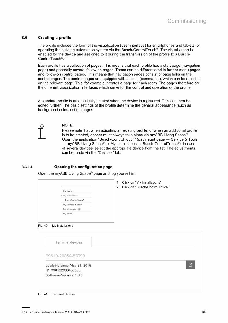
Commissioning
KNX Technical Reference Manual 2CKA001473B8903 │67
8.6 Creating a profile
The profile includes the form of the visualization (user interface) for smartphones and tablets for operating the building automation system via the Busch-ControlTouch®. The visualization is enabled for the device and assigned to it during the transmission of the profile to a Busch-ControlTouch®.
Each profile has a collection of pages. This means that each profile has a start page (navigation page) and generally several follow-on pages. These can be differentiated in further menu pages and follow-on control pages. This means that navigation pages consist of page links on the control pages. The control pages are equipped with actions (commands), which can be selected on the relevant page. This, for example, creates a page for each room. The pages therefore are the different visualization interfaces which serve for the control and operation of the profile.
A standard profile is automatically created when the device is registered. This can then be edited further. The basic settings of the profile determine the general appearance (such as background colour) of the pages.
NOTE Please note that when adjusting an existing profile, or when an additional profile is to be created, access must always take place via myABB Living Space®. Open the application "Busch-ControlTouch" (path: start page → Service & Tools → myABB Living Space® → My installations → Busch-ControlTouch®). In case of several devices, select the appropriate device from the list. The adjustments can be made via the "Devices" tab.
8.6.1.1 Opening the configuration page
Open the myABB Living Space® page and log yourself in.
1. Click on "My installations" 2. Click on "Busch-ControlTouch"
Fig. 40: My installations
Fig. 41: Terminal devices
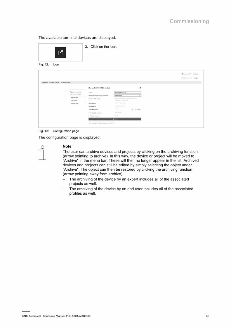
Commissioning
KNX Technical Reference Manual 2CKA001473B8903 │68
The available terminal devices are displayed.
3. Click on the icon.
Fig. 42: Icon
Fig. 43: Configuration page
The configuration page is displayed.
Note The user can archive devices and projects by clicking on the archiving function (arrow pointing to archive). In this way, the device or project will be moved to "Archive" in the menu bar. These will then no longer appear in the list. Archived devices and projects can still be edited by simply selecting the object under "Archive". The object can then be restored by clicking the archiving function (arrow pointing away from archive). – The archiving of the device by an expert includes all of the associated
projects as well. – The archiving of the device by an end user includes all of the associated
profiles as well.
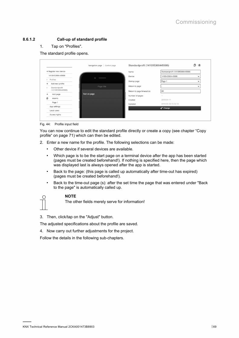
Commissioning
KNX Technical Reference Manual 2CKA001473B8903 │69
8.6.1.2 Call-up of standard profile
1. Tap on "Profiles".
The standard profile opens.
Fig. 44: Profile input field
You can now continue to edit the standard profile directly or create a copy (see chapter “Copy profile“ on page 71) which can then be edited.
2. Enter a new name for the profile. The following selections can be made:
■ Other device if several devices are available.
■ Which page is to be the start page on a terminal device after the app has been started (pages must be created beforehand!). If nothing is specified here, then the page which was displayed last is always opened after the app is started.
■ Back to the page: (this page is called up automatically after time-out has expired) (pages must be created beforehand!).
■ Back to the time-out page (s): after the set time the page that was entered under "Back to the page" is automatically called up.
NOTE The other fields merely serve for information!
3. Then, click/tap on the "Adjust" button.
The adjusted specifications about the profile are saved.
4. Now carry out further adjustments for the project.
Follow the details in the following sub-chapters.
Commissioning
KNX Technical Reference Manual 2CKA001473B8903 │70
NOTE Often it is easier to first select a profile that is similar to the profile to be created. This can then be copied (see chapter “Copy profile“ on page 71), with which a complete copy of the profile is prepared. This copy can then be adjusted.
The entry "Extended options" is only available if the fitter has enabled this option under "Devices"!
The standard page settings can be adjusted for the navigation and control pages. Here the colours of different components of the pages can be adjusted.
NOTE The individual options must be activated so that the adjustments can be transmitted. The colour values can be easily adjusted with entries in the input fields. They are taken over immediately by tapping on the "Adjust" button. The adjustments can then be checked immediately in the image of the iPhone. The adjustments made here generally apply to all navigation and control pages. However, also individual adjustments can be made for the individual pages (see chapter “Copy profile“ on page 71).
■ Background colour: Adjustment of the background colour for the entire page (without title block)
■ Background colour gradient:
Adjustment of the basic colour of the background colour gradient for the entire page (without title block)
■ Text colour: Adjustment of text colour on the entire page (without title block) ■ Separator colour: Adjustment of parting line between page contents (text blocks) ■ Title foreground colour: Adjustment of text colour of page title (only title block) ■ Title background colour: Adjustment of the background colour for the title block (only title block)
Commissioning
KNX Technical Reference Manual 2CKA001473B8903 │71
8.6.1.3 Create new profile
The procedure is as listed under item "Call up (standard) profile". However, here menu item "Add new profile" is called up.
Then a new profile (similar to "Standard profile") is added, which is listed in the menu column. This can then adjusted normally.
NOTE Often it is easier to first select a profile that is similar to the profile to be created. This can then be copied (see chapter “Copy profile“ on page 71), with which a complete copy of the profile is prepared. This copy can then be adjusted.
8.6.2 Copy profile
Each profile with all its data can be copied. The advantage is that one can take over a profile for which one wants to make only a few adjustments for a different end customer, for example.
1. Select the profile you wish to copy in the menu column.
The profile opens.
2. Tap on the copy icon in the top right.
3. The profile is copied and indicated in the menu column with [duplicated].
8.6.3 Delete profile
Each profile can also be deleted.
1. Select the profile you wish to delete in the right menu column.
The profile opens.
2. Tap on the rubbish bin icon.
3. Confirm the message.
The profile is deleted.
8.6.4 Profile backup
Profiles can be secured with a backup.
1. Select the profile you wish to back up in the menu column.
The profile opens.
2. Tap the cloud symbol (with plus).
The profile is backed up.
Note Backed-up profiles are stored in the "Backup" menu (see the menu column).
Commissioning
KNX Technical Reference Manual 2CKA001473B8903 │72
8.6.5 Restoring a backup profile
It is possible to restore a backup.
1. Select the "Backup" menu from the menu column. Then the desired backup must be selected.
2. Tap on the cloud symbol (with the arrow).
The profile is copied back to the normal list.
Note The backup can also be deleted from the menu.
8.6.6 Exporting a profile (export function)
Profiles can now be exported to a file and downloaded.
1. Select the profile to be exported from the menu column.
The profile opens.
2. Tap the download symbol.
3. Select a save location.
The profile is downloaded.
8.6.7 Importing a profile (import function)
The user can load (exported) profile files into the menu.
1. Select the function "Import Profile from File“ from the menu column.
2. Then the desired profile file can be selected.
3. Then tap "Open".
The profile is loaded to the menu.
8.6.8 Blocking a profile (blocking function)
A specialist can protect a profile from changes. By clicking on the lock symbol, the profile is protected from changes by the end user and the expert. The end user cannot unblock the profile; this is only possible by experts.
Note However, any user can copy the profile and then modify this copy.
1. Use the access point for specialists.
2. Select the profile you wish to block in the menu column.
The profile opens.
3. Tap the lock symbol (open). The profile is now blocked.
Note In order to unblock the blocked profile, open it as described above and repeat the process. The lock symbol is now closed.
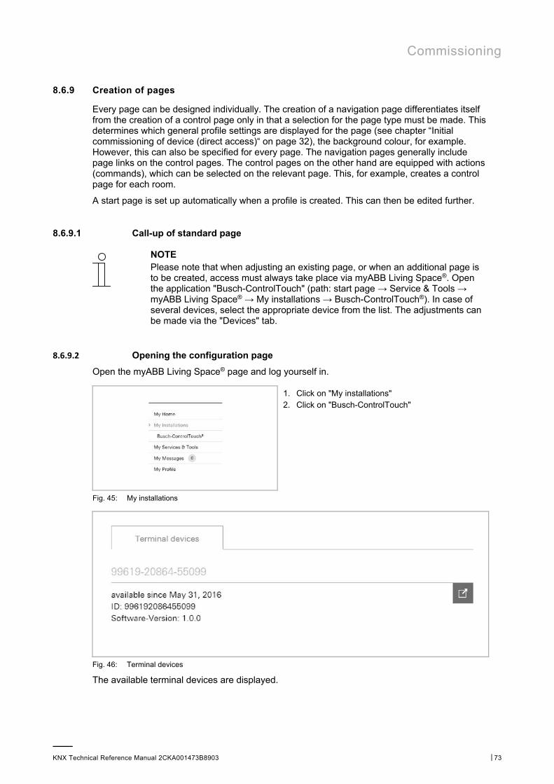
Commissioning
KNX Technical Reference Manual 2CKA001473B8903 │73
8.6.9 Creation of pages
Every page can be designed individually. The creation of a navigation page differentiates itself from the creation of a control page only in that a selection for the page type must be made. This determines which general profile settings are displayed for the page (see chapter “Initial commissioning of device (direct access)“ on page 32), the background colour, for example. However, this can also be specified for every page. The navigation pages generally include page links on the control pages. The control pages on the other hand are equipped with actions (commands), which can be selected on the relevant page. This, for example, creates a control page for each room.
A start page is set up automatically when a profile is created. This can then be edited further.
8.6.9.1 Call-up of standard page
NOTE Please note that when adjusting an existing page, or when an additional page is to be created, access must always take place via myABB Living Space®. Open the application "Busch-ControlTouch" (path: start page → Service & Tools → myABB Living Space® → My installations → Busch-ControlTouch®). In case of several devices, select the appropriate device from the list. The adjustments can be made via the "Devices" tab.
8.6.9.2 Opening the configuration page
Open the myABB Living Space® page and log yourself in.
1. Click on "My installations" 2. Click on "Busch-ControlTouch"
Fig. 45: My installations
Fig. 46: Terminal devices
The available terminal devices are displayed.
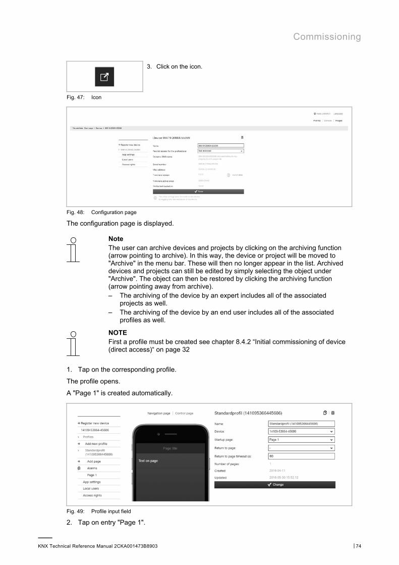
Commissioning
KNX Technical Reference Manual 2CKA001473B8903 │74
3. Click on the icon.
Fig. 47: Icon
Fig. 48: Configuration page
The configuration page is displayed.
Note The user can archive devices and projects by clicking on the archiving function (arrow pointing to archive). In this way, the device or project will be moved to "Archive" in the menu bar. These will then no longer appear in the list. Archived devices and projects can still be edited by simply selecting the object under "Archive". The object can then be restored by clicking the archiving function (arrow pointing away from archive). – The archiving of the device by an expert includes all of the associated
projects as well. – The archiving of the device by an end user includes all of the associated
profiles as well.
NOTE First a profile must be created see chapter 8.4.2 “Initial commissioning of device (direct access)“ on page 32
1. Tap on the corresponding profile.
The profile opens.
A "Page 1" is created automatically.
Fig. 49: Profile input field
2. Tap on entry "Page 1".
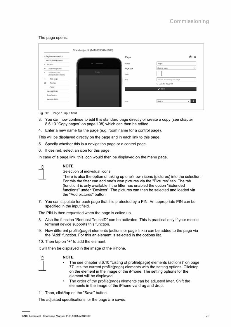
Commissioning
KNX Technical Reference Manual 2CKA001473B8903 │75
The page opens.
Fig. 50: Page 1 input field
3. You can now continue to edit this standard page directly or create a copy (see chapter 8.6.13 “Copy pages“ on page 108) which can then be edited.
4. Enter a new name for the page (e.g. room name for a control page).
This will be displayed directly on the page and in each link to this page.
5. Specify whether this is a navigation page or a control page.
6. If desired, select an icon for this page.
In case of a page link, this icon would then be displayed on the menu page.
NOTE Selection of individual icons: There is also the option of taking up one's own icons (pictures) into the selection. For this the fitter can add one's own pictures via the "Pictures" tab. The tab (function) is only available if the fitter has enabled the option "Extended functions" under "Devices". The pictures can then be selected and loaded via the "Add pictures" button.
7. You can stipulate for each page that it is protected by a PIN. An appropriate PIN can be specified in the input field.
The PIN is then requested when the page is called up.
8. Also the function "Request TouchID" can be activated. This is practical only if your mobile terminal device supports this function.
9. Now different profile(page) elements (actions or page links) can be added to the page via the "Add" function. For this an element is selected in the options list.
10. Then tap on "+" to add the element.
It will then be displayed in the image of the iPhone.
NOTE ■ The see chapter 8.6.10 “Listing of profile(page) elements (actions)“ on page
77 lists the current profile(page) elements with the setting options. Click/tap on the element in the image of the iPhone. The setting options for the element will be displayed.
■ The order of the profile(page) elements can be adjusted later. Shift the elements in the image of the iPhone via drag and drop.
11. Then, click/tap on the "Save" button.
The adjusted specifications for the page are saved.

Commissioning
KNX Technical Reference Manual 2CKA001473B8903 │76
NOTE Often it is easier to first select a page that is similar to the page to be created. This can then be copied (see chapter “Copy pages“ on page 108), with which a complete copy of the page is prepared. This copy can then be adjusted.
The entry "Extended options" is only available if the fitter has enabled this option under "Devices"!
The page settings can be adjusted individually. Here the colours of different components of the pages can be adjusted. Otherwise the general page settings for the navigation and control pages will be taken over from the profile.
NOTE The individual options must be activated so that the adjustments can be transmitted. The colour values can be easily adjusted with entries in the input fields. They are taken over immediately by tapping on the "Adjust" button. The adjustments can then be checked immediately in the image of the iPhone. The adjustments made here apply individually only to the edited page!
■ Background colour: Adjustment of the background colour for the entire page (without title block)
■ Background colour gradient:
Adjustment of the basic colour of the background colour gradient for the entire page (without title block)
■ Text colour: Adjustment of text colour on the entire page (without title block) ■ Separator colour: Adjustment of parting line between page contents (text blocks) ■ Title foreground colour: Adjustment of text colour of page title (only title block) ■ Title background colour: Adjustment of the background colour for the title block (only title block)
8.6.9.3 Create a new page
The procedure is as listed under item "Call up (standard) page". However, here menu item "Add new page" is called up.
Then a new page (similar to "Page 1") is added, which is listed in the menu column. This can then adjusted normally.
NOTE Often it is easier to first select a page that is similar to the page to be created. This can then be copied (see chapter “Copy pages“ on page 108), with which a complete copy of the page is prepared. This copy can then be adjusted.
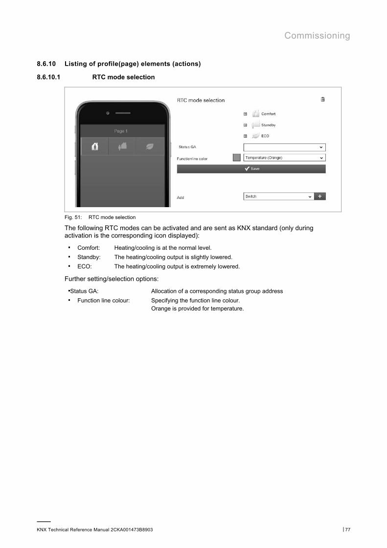
Commissioning
KNX Technical Reference Manual 2CKA001473B8903 │77
8.6.10 Listing of profile(page) elements (actions)
8.6.10.1 RTC mode selection
Fig. 51: RTC mode selection
The following RTC modes can be activated and are sent as KNX standard (only during activation is the corresponding icon displayed):
■ Comfort: Heating/cooling is at the normal level. ■ Standby: The heating/cooling output is slightly lowered. ■ ECO: The heating/cooling output is extremely lowered.
Further setting/selection options:
■Status GA: Allocation of a corresponding status group address ■ Function line colour: Specifying the function line colour.
Orange is provided for temperature.
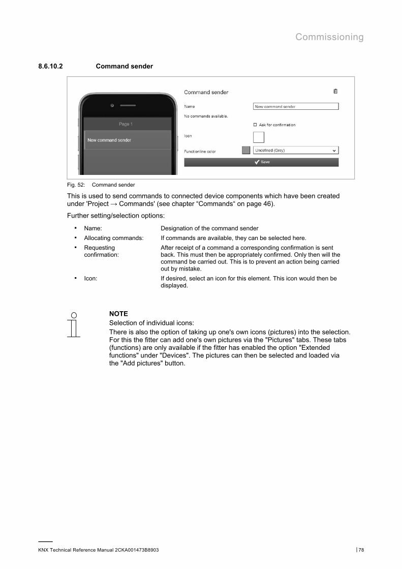
Commissioning
KNX Technical Reference Manual 2CKA001473B8903 │78
8.6.10.2 Command sender
Fig. 52: Command sender
This is used to send commands to connected device components which have been created under 'Project → Commands' (see chapter “Commands“ on page 46).
Further setting/selection options:
■ Name: Designation of the command sender ■ Allocating commands: If commands are available, they can be selected here. ■ Requesting
confirmation: After receipt of a command a corresponding confirmation is sent back. This must then be appropriately confirmed. Only then will the command be carried out. This is to prevent an action being carried out by mistake.
■ Icon: If desired, select an icon for this element. This icon would then be displayed.
NOTE Selection of individual icons: There is also the option of taking up one's own icons (pictures) into the selection. For this the fitter can add one's own pictures via the "Pictures" tabs. These tabs (functions) are only available if the fitter has enabled the option "Extended functions" under "Devices". The pictures can then be selected and loaded via the "Add pictures" button.

Commissioning
KNX Technical Reference Manual 2CKA001473B8903 │79
8.6.10.3 Display light intensity
Fig. 53: Display light intensity
This can be used to display the current light intensity of a selected element (group address).
Further setting/selection options:
■ Name: Designation of the status display for lighting intensity. ■ Lighting intensity: Allocation of a corresponding group address. ■ Function line colour: Specifying the function line colour.
Grey is provided for these types of functions.
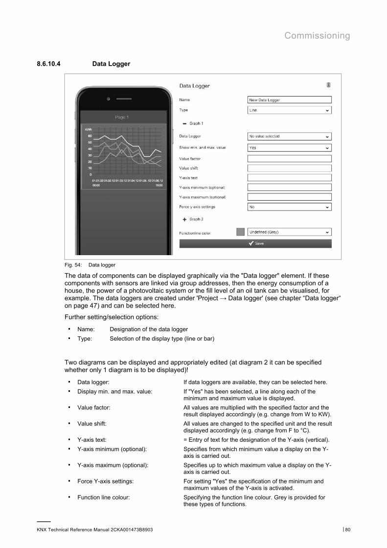
Commissioning
KNX Technical Reference Manual 2CKA001473B8903 │80
8.6.10.4 Data Logger
Fig. 54: Data logger
The data of components can be displayed graphically via the "Data logger" element. If these components with sensors are linked via group addresses, then the energy consumption of a house, the power of a photovoltaic system or the fill level of an oil tank can be visualised, for example. The data loggers are created under 'Project → Data logger' (see chapter “Data logger“ on page 47) and can be selected here.
Further setting/selection options:
■ Name: Designation of the data logger ■ Type: Selection of the display type (line or bar)
Two diagrams can be displayed and appropriately edited (at diagram 2 it can be specified whether only 1 diagram is to be displayed)!
■ Data logger: If data loggers are available, they can be selected here. ■ Display min. and max. value: If "Yes" has been selected, a line along each of the
minimum and maximum value is displayed. ■ Value factor: All values are multiplied with the specified factor and the
result displayed accordingly (e.g. change from W to KW). ■ Value shift: All values are changed to the specified unit and the result
displayed accordingly (e.g. change from F to °C). ■ Y-axis text: = Entry of text for the designation of the Y-axis (vertical). ■ Y-axis minimum (optional): Specifies from which minimum value a display on the Y-
axis is carried out. ■ Y-axis maximum (optional): Specifies up to which maximum value a display on the Y-
axis is carried out. ■ Force Y-axis settings: For setting "Yes" the specification of the minimum and
maximum values of the Y-axis is activated. ■ Function line colour: Specifying the function line colour. Grey is provided for
these types of functions.

Commissioning
KNX Technical Reference Manual 2CKA001473B8903 │81
8.6.10.5 Date / time
Fig. 55: Date/Time
Hereby the date and/or time is displayed (sending).
Further setting/selection options:
■ Name: Designation of date/time display ■ Type: Selection of time type:
– Current time: Current system time which, if possible, is continuously transmitted via the Internet.
– Sunrise: The time the sun rises at the location of the device.
– Sunset: The time the sun sets at the location of the device.
– Timestamp: A 4-byte value object is used to receive a timestamp via an external KNX device.
■ Display date: The date is displayed after activation. ■ Use USA date
format: The following date format is used after activation: Month/Day/Year.
■ Display time: The time is displayed according to the set time type after activation. ■ Use 24h format: The 24h format (e.g. 21:34, or 09:34 is displayed) is used for the time display
after activation. ■ Display seconds: Also the seconds are displayed after activation. ■ Continuous clock: The clock display continuous to run automatically after the start and is updated
during access to the Internet. ■ Function line
colour: Specifying the function line colour. Grey is provided for these types of functions.
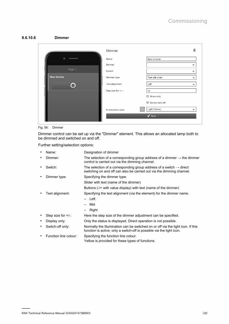
Commissioning
KNX Technical Reference Manual 2CKA001473B8903 │82
8.6.10.6 Dimmer
Fig. 56: Dimmer
Dimmer control can be set up via the "Dimmer" element. This allows an allocated lamp both to be dimmed and switched on and off.
Further setting/selection options:
■ Name: Designation of dimmer ■ Dimmer: The selection of a corresponding group address of a dimmer → the dimmer
control is carried out via the dimming channel. ■ Switch: The selection of a corresponding group address of a switch → direct
switching on and off can also be carried out via the dimming channel. ■ Dimmer type: Specifying the dimmer type:
Slider with text (name of the dimmer)
Buttons (-/+ with value display) with text (name of the dimmer) ■ Text alignment: Specifying the text alignment (via the element) for the dimmer name.
– Left
– Mid
– Right ■ Step size for +/-: Here the step size of the dimmer adjustment can be specified. ■ Display only: Only the status is displayed. Direct operation is not possible. ■ Switch-off only: Normally the Illumination can be switched on or off via the light icon. If this
function is active, only a switch-off is possible via the light icon. ■ Function line colour: Specifying the function line colour.
Yellow is provided for these types of functions.
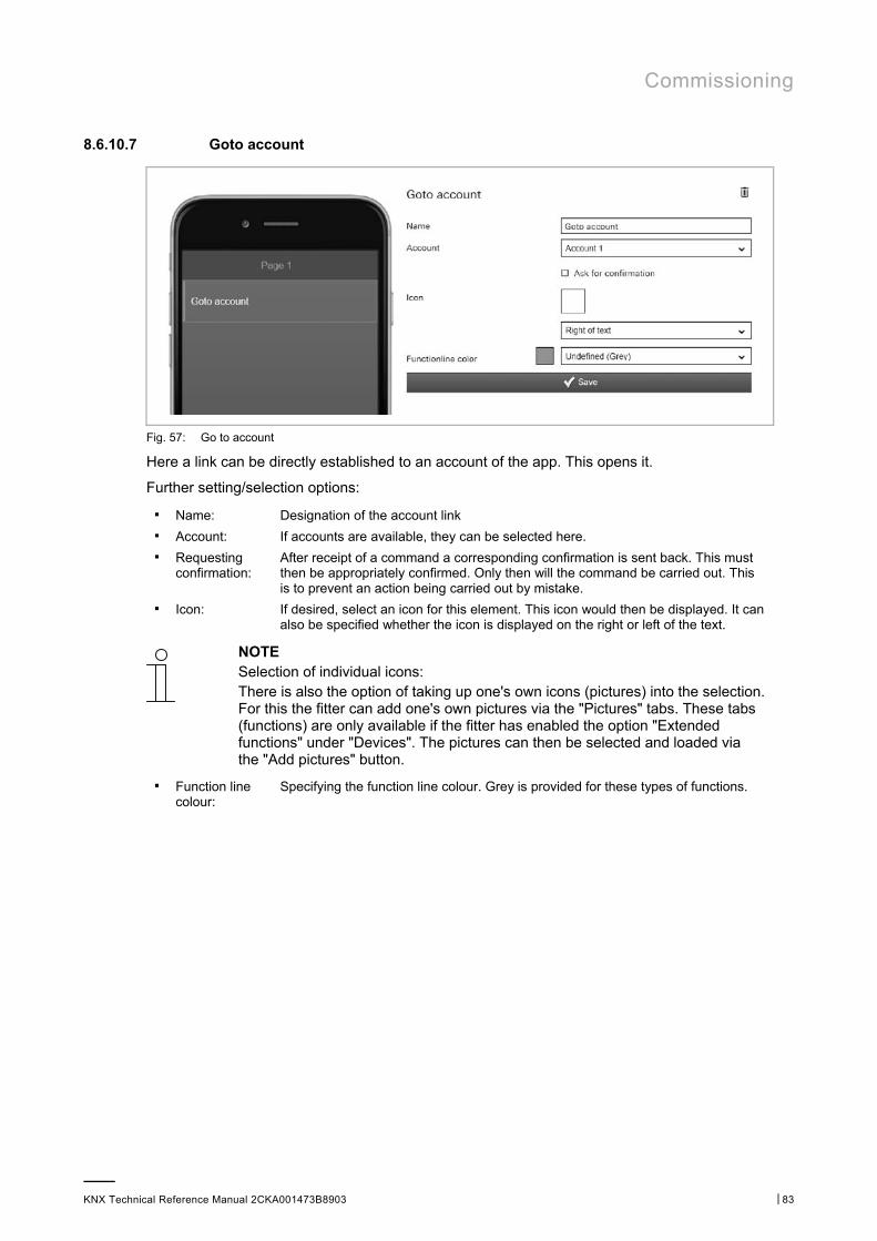
Commissioning
KNX Technical Reference Manual 2CKA001473B8903 │83
8.6.10.7 Goto account
Fig. 57: Go to account
Here a link can be directly established to an account of the app. This opens it.
Further setting/selection options:
■ Name: Designation of the account link ■ Account: If accounts are available, they can be selected here. ■ Requesting
confirmation: After receipt of a command a corresponding confirmation is sent back. This must then be appropriately confirmed. Only then will the command be carried out. This is to prevent an action being carried out by mistake.
■ Icon: If desired, select an icon for this element. This icon would then be displayed. It can also be specified whether the icon is displayed on the right or left of the text.
NOTE Selection of individual icons: There is also the option of taking up one's own icons (pictures) into the selection. For this the fitter can add one's own pictures via the "Pictures" tabs. These tabs (functions) are only available if the fitter has enabled the option "Extended functions" under "Devices". The pictures can then be selected and loaded via the "Add pictures" button.
■ Function line colour:
Specifying the function line colour. Grey is provided for these types of functions.
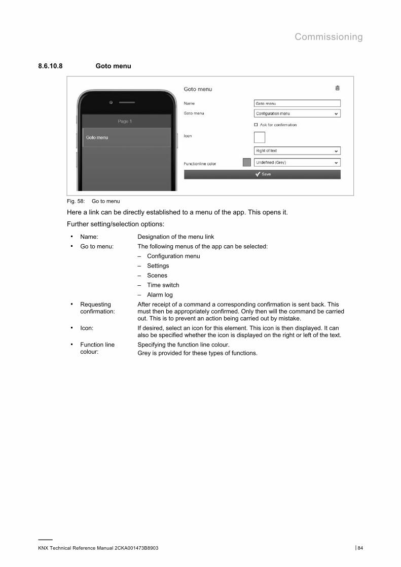
Commissioning
KNX Technical Reference Manual 2CKA001473B8903 │84
8.6.10.8 Goto menu
Fig. 58: Go to menu
Here a link can be directly established to a menu of the app. This opens it.
Further setting/selection options:
■ Name: Designation of the menu link ■ Go to menu: The following menus of the app can be selected:
– Configuration menu
– Settings
– Scenes
– Time switch
– Alarm log ■ Requesting
confirmation: After receipt of a command a corresponding confirmation is sent back. This must then be appropriately confirmed. Only then will the command be carried out. This is to prevent an action being carried out by mistake.
■ Icon: If desired, select an icon for this element. This icon is then displayed. It can also be specified whether the icon is displayed on the right or left of the text.
■ Function line colour:
Specifying the function line colour. Grey is provided for these types of functions.
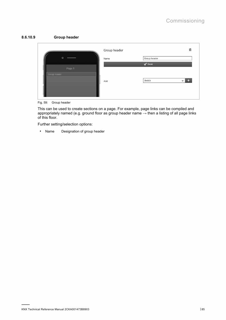
Commissioning
KNX Technical Reference Manual 2CKA001473B8903 │85
8.6.10.9 Group header
Fig. 59: Group header
This can be used to create sections on a page. For example, page links can be compiled and appropriately named (e.g. ground floor as group header name → then a listing of all page links of this floor.
Further setting/selection options:
■ Name Designation of group header
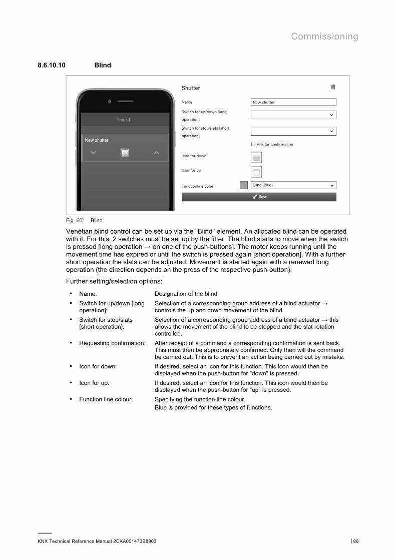
Commissioning
KNX Technical Reference Manual 2CKA001473B8903 │86
8.6.10.10 Blind
Fig. 60: Blind
Venetian blind control can be set up via the "Blind" element. An allocated blind can be operated with it. For this, 2 switches must be set up by the fitter. The blind starts to move when the switch is pressed [long operation → on one of the push-buttons]. The motor keeps running until the movement time has expired or until the switch is pressed again [short operation]. With a further short operation the slats can be adjusted. Movement is started again with a renewed long operation (the direction depends on the press of the respective push-button).
Further setting/selection options:
■ Name: Designation of the blind ■ Switch for up/down [long
operation]: Selection of a corresponding group address of a blind actuator → controls the up and down movement of the blind.
■ Switch for stop/slats [short operation]:
Selection of a corresponding group address of a blind actuator → this allows the movement of the blind to be stopped and the slat rotation controlled.
■ Requesting confirmation: After receipt of a command a corresponding confirmation is sent back. This must then be appropriately confirmed. Only then will the command be carried out. This is to prevent an action being carried out by mistake.
■ Icon for down: If desired, select an icon for this function. This icon would then be displayed when the push-button for "down" is pressed.
■ Icon for up: If desired, select an icon for this function. This icon would then be displayed when the push-button for "up" is pressed.
■ Function line colour: Specifying the function line colour. Blue is provided for these types of functions.
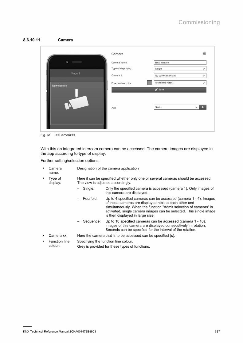
Commissioning
KNX Technical Reference Manual 2CKA001473B8903 │87
8.6.10.11 Camera
Fig. 61: >>Camera<<
With this an integrated intercom camera can be accessed. The camera images are displayed in the app according to type of display.
Further setting/selection options:
■ Camera name:
Designation of the camera application
■ Type of display:
Here it can be specified whether only one or several cameras should be accessed. The view is adjusted accordingly.
– Single: Only the specified camera is accessed (camera 1). Only images of this camera are displayed.
– Fourfold: Up to 4 specified cameras can be accessed (camera 1 - 4). Images of these cameras are displayed next to each other and simultaneously. When the function "Admit selection of cameras" is activated, single camera images can be selected. This single image is then displayed in large size.
– Sequence: Up to 10 specified cameras can be accessed (camera 1 - 10). Images of this camera are displayed consecutively in rotation. Seconds can be specified for the interval of the rotation.
■ Camera xx: Here the camera that is to be accessed can be specified (s). ■ Function line
colour: Specifying the function line colour. Grey is provided for these types of functions.
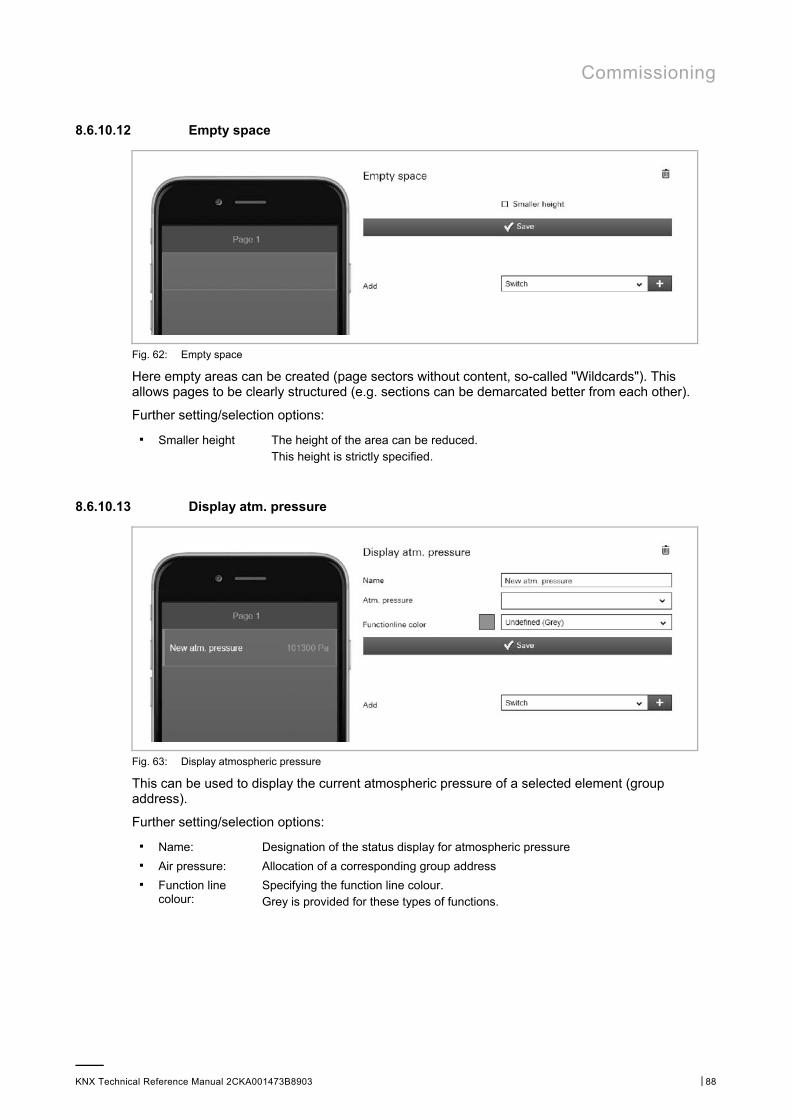
Commissioning
KNX Technical Reference Manual 2CKA001473B8903 │88
8.6.10.12 Empty space
Fig. 62: Empty space
Here empty areas can be created (page sectors without content, so-called "Wildcards"). This allows pages to be clearly structured (e.g. sections can be demarcated better from each other).
Further setting/selection options:
■ Smaller height The height of the area can be reduced. This height is strictly specified.
8.6.10.13 Display atm. pressure
Fig. 63: Display atmospheric pressure
This can be used to display the current atmospheric pressure of a selected element (group address).
Further setting/selection options:
■ Name: Designation of the status display for atmospheric pressure ■ Air pressure: Allocation of a corresponding group address ■ Function line
colour: Specifying the function line colour. Grey is provided for these types of functions.
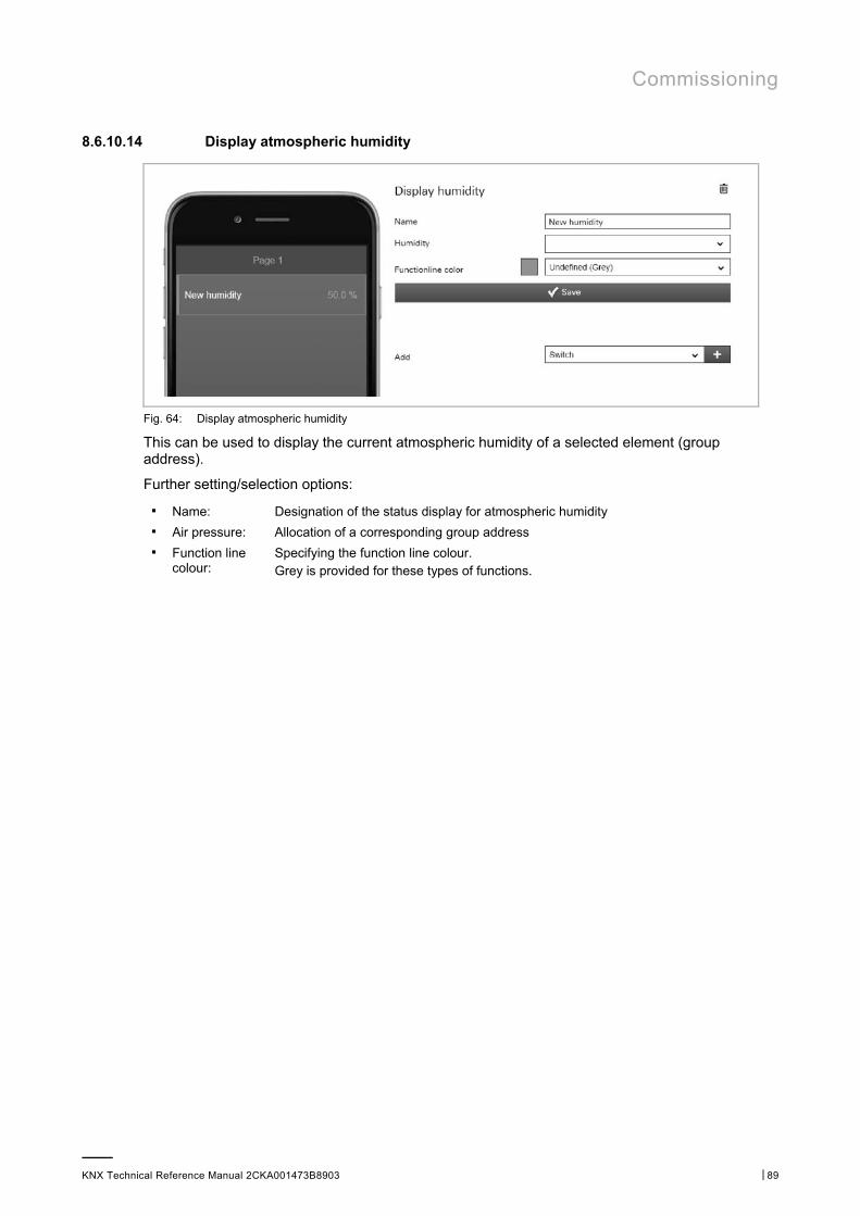
Commissioning
KNX Technical Reference Manual 2CKA001473B8903 │89
8.6.10.14 Display atmospheric humidity
Fig. 64: Display atmospheric humidity
This can be used to display the current atmospheric humidity of a selected element (group address).
Further setting/selection options:
■ Name: Designation of the status display for atmospheric humidity ■ Air pressure: Allocation of a corresponding group address ■ Function line
colour: Specifying the function line colour. Grey is provided for these types of functions.
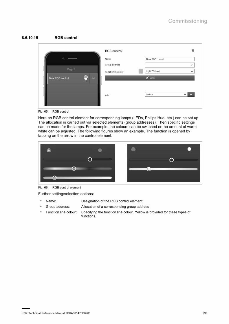
Commissioning
KNX Technical Reference Manual 2CKA001473B8903 │90
8.6.10.15 RGB control
Fig. 65: RGB control
Here an RGB control element for corresponding lamps (LEDs, Philips Hue, etc.) can be set up. The allocation is carried out via selected elements (group addresses). Then specific settings can be made for the lamps. For example, the colours can be switched or the amount of warm white can be adjusted. The following figures show an example. The function is opened by tapping on the arrow in the control element.
Fig. 66: RGB control element
Further setting/selection options:
■ Name: Designation of the RGB control element: ■ Group address: Allocation of a corresponding group address ■ Function line colour: Specifying the function line colour. Yellow is provided for these types of
functions.
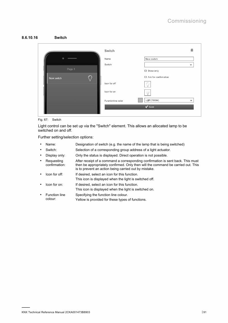
Commissioning
KNX Technical Reference Manual 2CKA001473B8903 │91
8.6.10.16 Switch
Fig. 67: Switch
Light control can be set up via the "Switch" element. This allows an allocated lamp to be switched on and off.
Further setting/selection options:
■ Name: Designation of switch (e.g. the name of the lamp that is being switched) ■ Switch: Selection of a corresponding group address of a light actuator. ■ Display only: Only the status is displayed. Direct operation is not possible. ■ Requesting
confirmation: After receipt of a command a corresponding confirmation is sent back. This must then be appropriately confirmed. Only then will the command be carried out. This is to prevent an action being carried out by mistake.
■ Icon for off: If desired, select an icon for this function. This icon is displayed when the light is switched off.
■ Icon for on: If desired, select an icon for this function. This icon is displayed when the light is switched on.
■ Function line colour:
Specifying the function line colour. Yellow is provided for these types of functions.
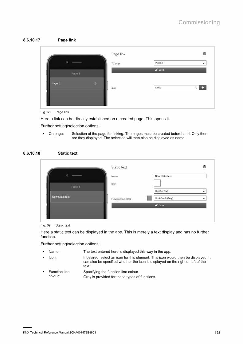
Commissioning
KNX Technical Reference Manual 2CKA001473B8903 │92
8.6.10.17 Page link
Fig. 68: Page link
Here a link can be directly established on a created page. This opens it.
Further setting/selection options:
■ On page: Selection of the page for linking. The pages must be created beforehand. Only then are they displayed. The selection will then also be displayed as name.
8.6.10.18 Static text
Fig. 69: Static text
Here a static text can be displayed in the app. This is merely a text display and has no further function.
Further setting/selection options:
■ Name: The text entered here is displayed this way in the app. ■ Icon: If desired, select an icon for this element. This icon would then be displayed. It
can also be specified whether the icon is displayed on the right or left of the text.
■ Function line colour:
Specifying the function line colour. Grey is provided for these types of functions.

Commissioning
KNX Technical Reference Manual 2CKA001473B8903 │93
8.6.10.19 Scene
Fig. 70: Scene
A scene can be allocated via the "Scene" element. The scene is started by clicking/tapping on this element. The scenes must be created beforehand by the fitter.
Further setting/selection options:
■ Name: Designation of the scene (e.g. wakeup) ■ Scene: Selection of a corresponding group address of a scene. ■ Requesting
confirmation: After receipt of a command a corresponding confirmation is sent back. This must then be appropriately confirmed. Only then will the command be carried out. This is to prevent an action being carried out by mistake.
■ Icon: If desired, select an icon for this element. This icon is then displayed. It can also be specified whether the icon is displayed on the right or left of the text.
■ Function line colour:
Specifying the function line colour. Magenta is provided for these types of functions.
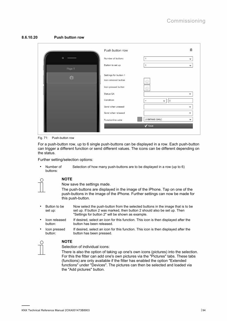
Commissioning
KNX Technical Reference Manual 2CKA001473B8903 │94
8.6.10.20 Push button row
Fig. 71: Push-button row
For a push-button row, up to 6 single push-buttons can be displayed in a row. Each push-button can trigger a different function or send different values. The icons can be different depending on the status.
Further setting/selection options:
■ Number of buttons:
Selection of how many push-buttons are to be displayed in a row (up to 6)
NOTE Now save the settings made. The push-buttons are displayed in the image of the iPhone. Tap on one of the push-buttons in the image of the iPhone. Further settings can now be made for this push-button.
■ Button to be set up:
Now select the push-button from the selected buttons in the image that is to be set up. If button 2 was marked, then button 2 should also be set up. Then "Settings for button 2" will be shown as example.
■ Icon released button:
If desired, select an icon for this function. This icon is then displayed after the button has been released.
■ Icon pressed button:
If desired, select an icon for this function. This icon is then displayed after the button has been pressed.
NOTE Selection of individual icons: There is also the option of taking up one's own icons (pictures) into the selection. For this the fitter can add one's own pictures via the "Pictures" tabs. These tabs (functions) are only available if the fitter has enabled the option "Extended functions" under "Devices". The pictures can then be selected and loaded via the "Add pictures" button.
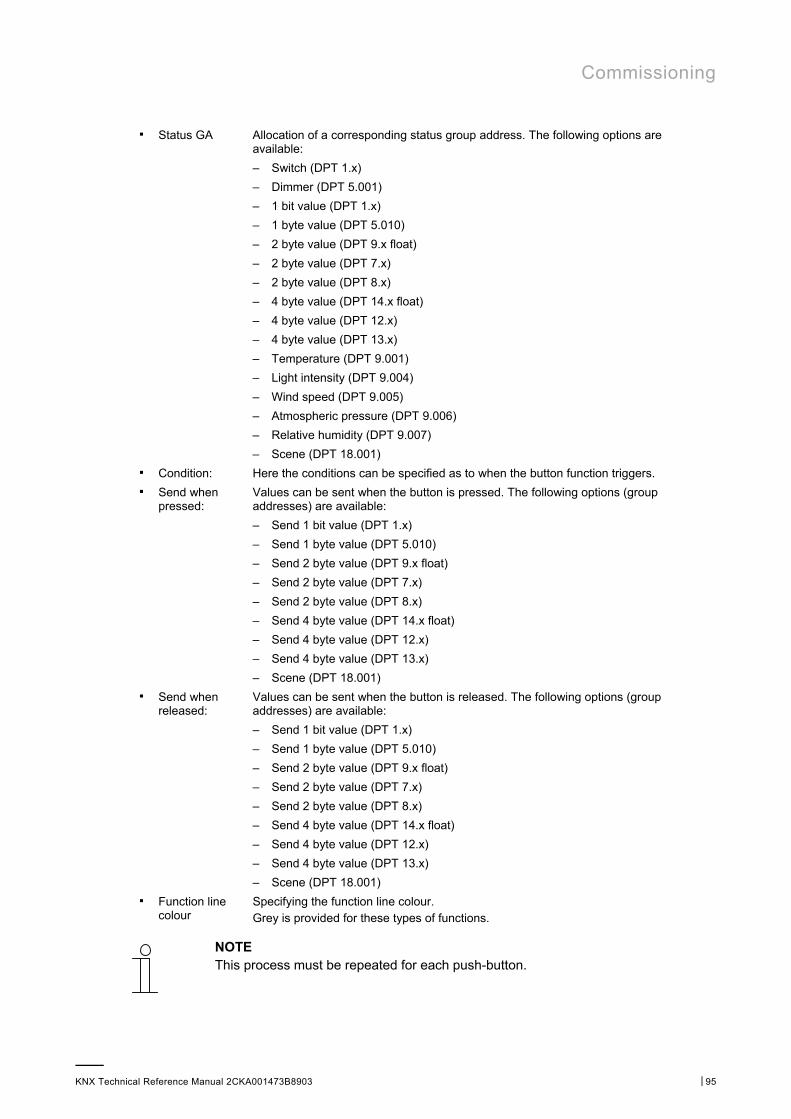
Commissioning
KNX Technical Reference Manual 2CKA001473B8903 │95
■ Status GA Allocation of a corresponding status group address. The following options are available:
– Switch (DPT 1.x)
– Dimmer (DPT 5.001)
– 1 bit value (DPT 1.x)
– 1 byte value (DPT 5.010)
– 2 byte value (DPT 9.x float)
– 2 byte value (DPT 7.x)
– 2 byte value (DPT 8.x)
– 4 byte value (DPT 14.x float)
– 4 byte value (DPT 12.x)
– 4 byte value (DPT 13.x)
– Temperature (DPT 9.001)
– Light intensity (DPT 9.004)
– Wind speed (DPT 9.005)
– Atmospheric pressure (DPT 9.006)
– Relative humidity (DPT 9.007)
– Scene (DPT 18.001) ■ Condition: Here the conditions can be specified as to when the button function triggers. ■ Send when
pressed: Values can be sent when the button is pressed. The following options (group addresses) are available:
– Send 1 bit value (DPT 1.x)
– Send 1 byte value (DPT 5.010)
– Send 2 byte value (DPT 9.x float)
– Send 2 byte value (DPT 7.x)
– Send 2 byte value (DPT 8.x)
– Send 4 byte value (DPT 14.x float)
– Send 4 byte value (DPT 12.x)
– Send 4 byte value (DPT 13.x)
– Scene (DPT 18.001) ■ Send when
released: Values can be sent when the button is released. The following options (group addresses) are available:
– Send 1 bit value (DPT 1.x)
– Send 1 byte value (DPT 5.010)
– Send 2 byte value (DPT 9.x float)
– Send 2 byte value (DPT 7.x)
– Send 2 byte value (DPT 8.x)
– Send 4 byte value (DPT 14.x float)
– Send 4 byte value (DPT 12.x)
– Send 4 byte value (DPT 13.x)
– Scene (DPT 18.001) ■ Function line
colour Specifying the function line colour. Grey is provided for these types of functions.
NOTE This process must be repeated for each push-button.
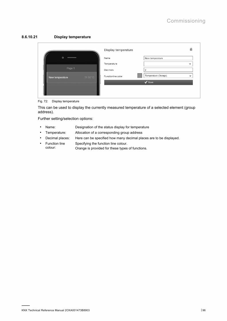
Commissioning
KNX Technical Reference Manual 2CKA001473B8903 │96
8.6.10.21 Display temperature
Fig. 72: Display temperature
This can be used to display the currently measured temperature of a selected element (group address).
Further setting/selection options:
■ Name: Designation of the status display for temperature ■ Temperature: Allocation of a corresponding group address ■ Decimal places: Here can be specified how many decimal places are to be displayed. ■ Function line
colour: Specifying the function line colour. Orange is provided for these types of functions.
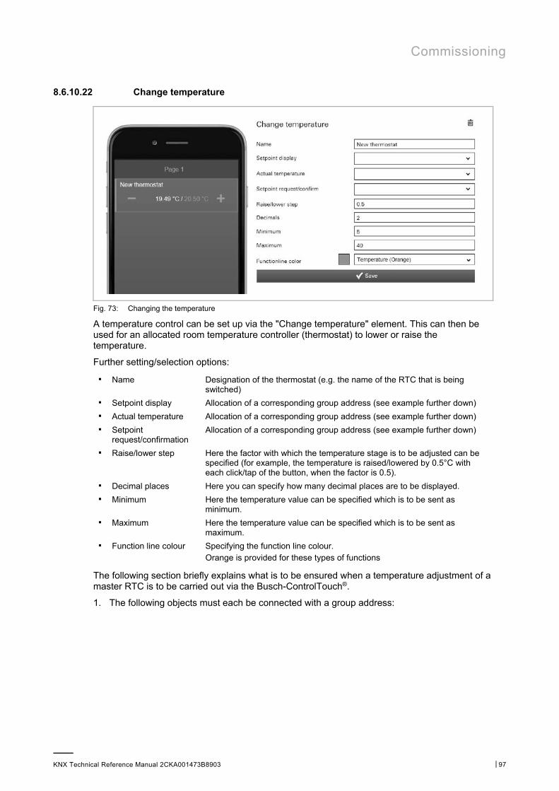
Commissioning
KNX Technical Reference Manual 2CKA001473B8903 │97
8.6.10.22 Change temperature
Fig. 73: Changing the temperature
A temperature control can be set up via the "Change temperature" element. This can then be used for an allocated room temperature controller (thermostat) to lower or raise the temperature.
Further setting/selection options:
■ Name Designation of the thermostat (e.g. the name of the RTC that is being switched)
■ Setpoint display Allocation of a corresponding group address (see example further down) ■ Actual temperature Allocation of a corresponding group address (see example further down) ■ Setpoint
request/confirmation Allocation of a corresponding group address (see example further down)
■ Raise/lower step Here the factor with which the temperature stage is to be adjusted can be specified (for example, the temperature is raised/lowered by 0.5°C with each click/tap of the button, when the factor is 0.5).
■ Decimal places Here you can specify how many decimal places are to be displayed. ■ Minimum Here the temperature value can be specified which is to be sent as
minimum. ■ Maximum Here the temperature value can be specified which is to be sent as
maximum. ■ Function line colour Specifying the function line colour.
Orange is provided for these types of functions
The following section briefly explains what is to be ensured when a temperature adjustment of a master RTC is to be carried out via the Busch-ControlTouch®.
1. The following objects must each be connected with a group address:
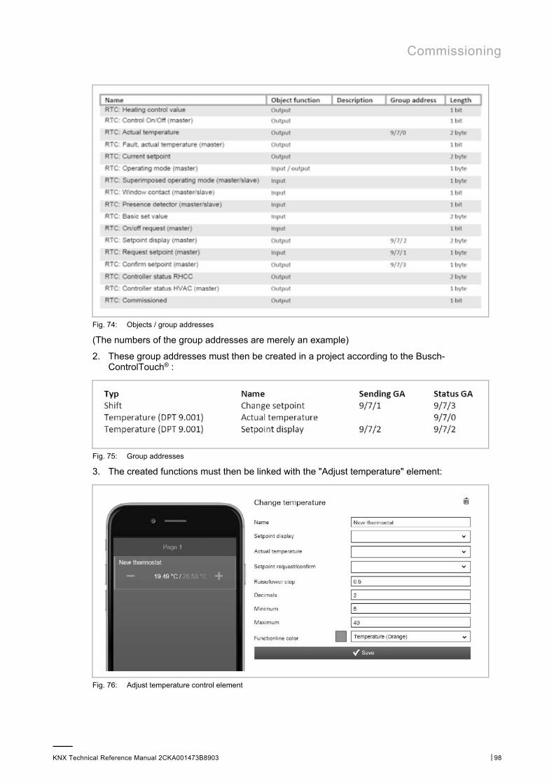
Commissioning
KNX Technical Reference Manual 2CKA001473B8903 │98
Fig. 74: Objects / group addresses
(The numbers of the group addresses are merely an example)
2. These group addresses must then be created in a project according to the Busch-ControlTouch® :
Fig. 75: Group addresses
3. The created functions must then be linked with the "Adjust temperature" element:
Fig. 76: Adjust temperature control element
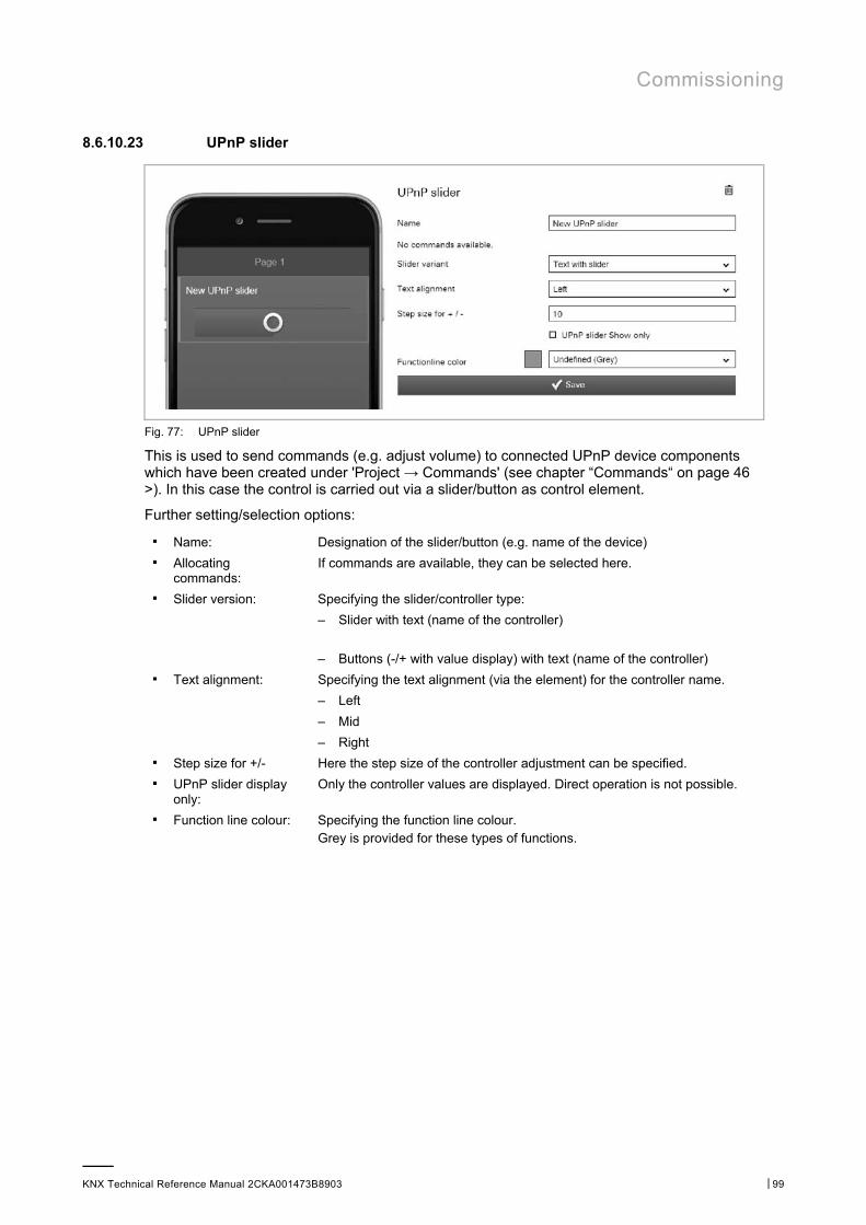
Commissioning
KNX Technical Reference Manual 2CKA001473B8903 │99
8.6.10.23 UPnP slider
Fig. 77: UPnP slider
This is used to send commands (e.g. adjust volume) to connected UPnP device components which have been created under 'Project → Commands' (see chapter “Commands“ on page 46 >). In this case the control is carried out via a slider/button as control element.
Further setting/selection options:
■ Name: Designation of the slider/button (e.g. name of the device) ■ Allocating
commands: If commands are available, they can be selected here.
■ Slider version: Specifying the slider/controller type:
– Slider with text (name of the controller)
– Buttons (-/+ with value display) with text (name of the controller) ■ Text alignment: Specifying the text alignment (via the element) for the controller name.
– Left
– Mid
– Right ■ Step size for +/- Here the step size of the controller adjustment can be specified. ■ UPnP slider display
only: Only the controller values are displayed. Direct operation is not possible.
■ Function line colour: Specifying the function line colour. Grey is provided for these types of functions.
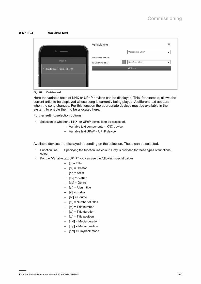
Commissioning
KNX Technical Reference Manual 2CKA001473B8903 │100
8.6.10.24 Variable text
Fig. 78: Variable text
Here the variable texts of KNX or UPnP devices can be displayed. This, for example, allows the current artist to be displayed whose song is currently being played. A different text appears when the song changes. For this function the appropriate devices must be available in the system, to enable them to be allocated here.
Further setting/selection options:
■ Selection of whether a KNX- or UPnP device is to be accessed.
– Variable text components = KNX device
– Variable text UPnP = UPnP device
Available devices are displayed depending on the selection. These can be selected.
■ Function line colour
Specifying the function line colour. Grey is provided for these types of functions.
■ For the "Variable text UPnP" you can use the following special values.
– [tt] = Title
– [cr] = Creator
– [ar] = Artist
– [au] = Author
– [ge] = Genre
– [at] = Album title
– [st] = Status
– [so] = Source
– [nt] = Number of titles
– [tn] = Title number
– [td] = Title duration
– [tp] = Title position
– [md] = Media duration
– [mp] = Media position
– [pm] = Playback mode
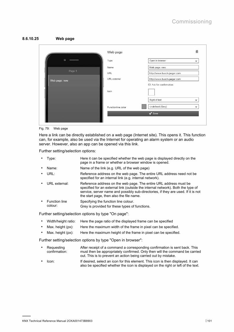
Commissioning
KNX Technical Reference Manual 2CKA001473B8903 │101
8.6.10.25 Web page
Fig. 79: Web page
Here a link can be directly established on a web page (Internet site). This opens it. This function can, for example, also be used via the Internet for operating an alarm system or an audio server. However, also an app can be opened via this link.
Further setting/selection options:
■ Type: Here it can be specified whether the web page is displayed directly on the page in a frame or whether a browser window is opened.
■ Name: Name of the link (e.g. URL of the web page) ■ URL: Reference address on the web page. The entire URL address need not be
specified for an internal link (e.g. internal network). ■ URL external: Reference address on the web page. The entire URL address must be
specified for an external link (outside the internal network). Both the type of service, server name and possibly sub-directories, if they are used. If it is not the start page, then also the file name.
■ Function line colour:
Specifying the function line colour. Grey is provided for these types of functions.
Further setting/selection options by type "On page":
■ Width/height ratio: Here the page ratio of the displayed frame can be specified ■ Max. height (px): Here the maximum width of the frame in pixel can be specified. ■ Max. height (px): Here the maximum height of the frame in pixel can be specified.
Further setting/selection options by type "Open in browser":
■ Requesting confirmation:
After receipt of a command a corresponding confirmation is sent back. This must then be appropriately confirmed. Only then will the command be carried out. This is to prevent an action being carried out by mistake.
■ Icon: If desired, select an icon for this element. This icon is then displayed. It can also be specified whether the icon is displayed on the right or left of the text.
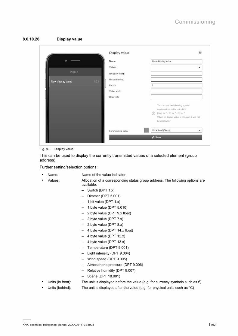
Commissioning
KNX Technical Reference Manual 2CKA001473B8903 │102
8.6.10.26 Display value
Fig. 80: Display value
This can be used to display the currently transmitted values of a selected element (group address).
Further setting/selection options:
■ Name: Name of the value indicator. ■ Values: Allocation of a corresponding status group address. The following options are
available:
– Switch (DPT 1.x)
– Dimmer (DPT 5.001)
– 1 bit value (DPT 1.x)
– 1 byte value (DPT 5.010)
– 2 byte value (DPT 9.x float)
– 2 byte value (DPT 7.x)
– 2 byte value (DPT 8.x)
– 4 byte value (DPT 14.x float)
– 4 byte value (DPT 12.x)
– 4 byte value (DPT 13.x)
– Temperature (DPT 9.001)
– Light intensity (DPT 9.004)
– Wind speed (DPT 9.005)
– Atmospheric pressure (DPT 9.006)
– Relative humidity (DPT 9.007)
– Scene (DPT 18.001) ■ Units (in front): The unit is displayed before the value (e.g. for currency symbols such as €) ■ Units (behind): The unit is displayed after the value (e.g. for physical units such as °C)

Commissioning
KNX Technical Reference Manual 2CKA001473B8903 │103
NOTE You can use the following special combinations in the units field: [deg] for ° - [2] for 2 - [3] for 3 If no display value has been selected, nothing will displayed.
■ Value factor: = All values are multiplied with the specified factor and the result displayed accordingly (e.g. change from W to KW).
■ Value shift: All values are changed to the specified unit and the result displayed accordingly (e.g. change from F to °C).
■ Decimal places: Here can be specified how many decimal places are to be displayed. ■ Function line
colour: Specifying the function line colour. Grey is provided for these types of functions.
8.6.10.27 Value controller
Fig. 81: Value controller
This can be used to display the values of a selected element (group address) and to adjust them at the same time via push-buttons. When they adjusted, the values are always displayed updated. This allows the values to be sent and received.
Further setting/selection options:
■ Name: Name of value controller (e.g. designation of the device). ■ Value object Allocation of a corresponding group address. Values are sent. The following
options are available:
– Switch (DPT 1.x)
– Dimmer (DPT 5.001)
– 1 bit value (DPT 1.x)
– 1 byte value (DPT 5.010)
– 2 byte value (DPT 9.x float)
– 2 byte value (DPT 7.x)
– 2 byte value (DPT 8.x)
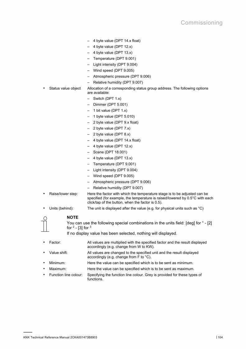
Commissioning
KNX Technical Reference Manual 2CKA001473B8903 │104
– 4 byte value (DPT 14.x float)
– 4 byte value (DPT 12.x)
– 4 byte value (DPT 13.x)
– Temperature (DPT 9.001)
– Light intensity (DPT 9.004)
– Wind speed (DPT 9.005)
– Atmospheric pressure (DPT 9.006)
– Relative humidity (DPT 9.007) ■ Status value object Allocation of a corresponding status group address. The following options
are available:
– Switch (DPT 1.x)
– Dimmer (DPT 5.001)
– 1 bit value (DPT 1.x)
– 1 byte value (DPT 5.010)
– 2 byte value (DPT 9.x float)
– 2 byte value (DPT 7.x)
– 2 byte value (DPT 8.x)
– 4 byte value (DPT 14.x float)
– 4 byte value (DPT 12.x)
– Scene (DPT 18.001)
– 4 byte value (DPT 13.x)
– Temperature (DPT 9.001)
– Light intensity (DPT 9.004)
– Wind speed (DPT 9.005)
– Atmospheric pressure (DPT 9.006)
– Relative humidity (DPT 9.007) ■ Raise/lower step: Here the factor with which the temperature stage is to be adjusted can be
specified (for example, the temperature is raised/lowered by 0.5°C with each click/tap of the button, when the factor is 0.5).
■ Units (behind): The unit is displayed after the value (e.g. for physical units such as °C)
NOTE You can use the following special combinations in the units field: [deg] for ° - [2] for 2 - [3] for 3 If no display value has been selected, nothing will displayed.
■ Factor: All values are multiplied with the specified factor and the result displayed accordingly (e.g. change from W to KW).
■ Value shift: All values are changed to the specified unit and the result displayed accordingly (e.g. change from F to °C).
■ Minimum: Here the value can be specified which is to be sent as minimum. ■ Maximum: Here the value can be specified which is to be sent as maximum. ■ Function line colour: Specifying the function line colour. Grey is provided for these types of
functions.

Commissioning
KNX Technical Reference Manual 2CKA001473B8903 │105
8.6.10.28 Value transmitter
Fig. 82: Value transmitter
Here values can be sent to a selected element (group address).
Further setting/selection options:
■ Name: Name of value transmitter (e.g. designation of the device). ■ Send value: Allocation of a corresponding group address. Values are sent. The following
options are available:
– Send 1 bit value (DPT 1.x)
– Send 1 byte value (DPT 5.010)
– Send 2 byte value (DPT 9.x float)
– Send 2 byte value (DPT 7.x)
– Send 2 byte value (DPT 8.x)
– Send 4 byte value (DPT 14.x float)
– Send 4 byte value (DPT 12.x)
– Send 4 byte value (DPT 13.x) ■ Requesting
confirmation: After receipt of a command a corresponding confirmation is sent back. This must then be appropriately confirmed. Only then will the command be carried out. This is to prevent an action being carried out by mistake.
■ Icon: If desired, select an icon for this element. This icon is then displayed. It can also be specified whether the icon is displayed on the right or left of the text.
■ Function line colour: Specifying the function line colour. Grey is provided for these types of functions.
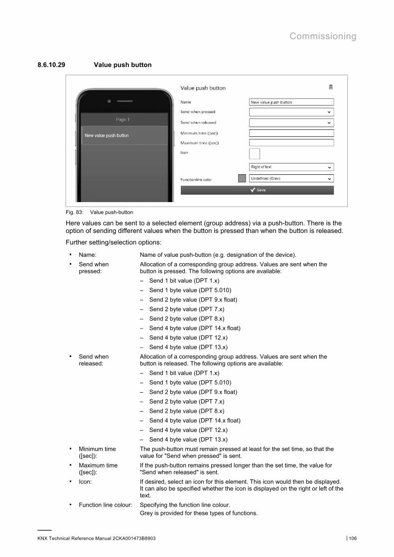
Commissioning
KNX Technical Reference Manual 2CKA001473B8903 │106
8.6.10.29 Value push button
Fig. 83: Value push-button
Here values can be sent to a selected element (group address) via a push-button. There is the option of sending different values when the button is pressed than when the button is released.
Further setting/selection options:
■ Name: Name of value push-button (e.g. designation of the device). ■ Send when
pressed: Allocation of a corresponding group address. Values are sent when the button is pressed. The following options are available:
– Send 1 bit value (DPT 1.x)
– Send 1 byte value (DPT 5.010)
– Send 2 byte value (DPT 9.x float)
– Send 2 byte value (DPT 7.x)
– Send 2 byte value (DPT 8.x)
– Send 4 byte value (DPT 14.x float)
– Send 4 byte value (DPT 12.x)
– Send 4 byte value (DPT 13.x) ■ Send when
released: Allocation of a corresponding group address. Values are sent when the button is released. The following options are available:
– Send 1 bit value (DPT 1.x)
– Send 1 byte value (DPT 5.010)
– Send 2 byte value (DPT 9.x float)
– Send 2 byte value (DPT 7.x)
– Send 2 byte value (DPT 8.x)
– Send 4 byte value (DPT 14.x float)
– Send 4 byte value (DPT 12.x)
– Send 4 byte value (DPT 13.x) ■ Minimum time
([sec]): The push-button must remain pressed at least for the set time, so that the value for "Send when pressed" is sent.
■ Maximum time ([sec]):
If the push-button remains pressed longer than the set time, the value for "Send when released" is sent.
■ Icon: If desired, select an icon for this element. This icon would then be displayed. It can also be specified whether the icon is displayed on the right or left of the text.
■ Function line colour: Specifying the function line colour. Grey is provided for these types of functions.
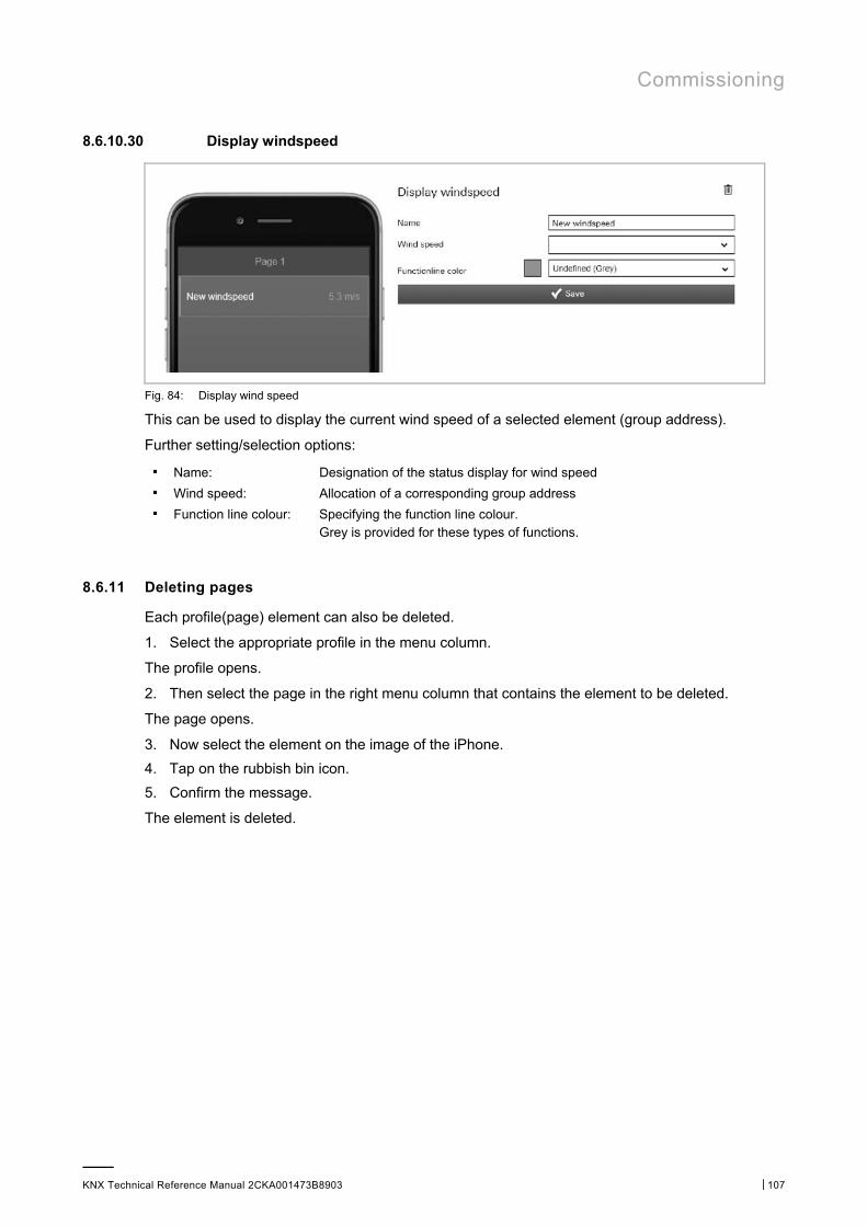
Commissioning
KNX Technical Reference Manual 2CKA001473B8903 │107
8.6.10.30 Display windspeed
Fig. 84: Display wind speed
This can be used to display the current wind speed of a selected element (group address).
Further setting/selection options:
■ Name: Designation of the status display for wind speed ■ Wind speed: Allocation of a corresponding group address ■ Function line colour: Specifying the function line colour.
Grey is provided for these types of functions.
8.6.11 Deleting pages
Each profile(page) element can also be deleted.
1. Select the appropriate profile in the menu column.
The profile opens.
2. Then select the page in the right menu column that contains the element to be deleted.
The page opens.
3. Now select the element on the image of the iPhone.
4. Tap on the rubbish bin icon.
5. Confirm the message.
The element is deleted.
Commissioning
KNX Technical Reference Manual 2CKA001473B8903 │108
8.6.12 Copying the page element
Each profile (page) element can also be copied along with all of its settings.
1. Select the appropriate profile in the menu column.
The profile opens.
2. Then select the page in the right menu column that contains the element to be copied.
The page opens.
3. Now select the element on the image of the iPhone.
4. Tap on the copy icon.
5. The element is copied and displayed in the page setting with the addendum "Paste element".
6. Tap the "Paste element" option to insert the copied page element into the opened page.
Note If the copied page element is to be moved to another page, another page must first be selected.
8.6.13 Copy pages
Each page with all its data can be copied. The advantage is that one can take over a page on which one wants to make only a few adjustments for a different end customer, for example.
1. Select the appropriate profile in the menu column.
The profile opens.
2. Then select the page you wish to copy in the menu column.
The page opens.
3. Tap on the copy icon.
4. The page is copied and the entry "Insert page" appears in the menu column.
5. Tap the "Insert page" option to insert the copied page into the open profile.
Note If the copied page is to be moved to another profile, another profile must first be selected.
8.6.14 Deleting pages
Each page can also be deleted.
1. Select the appropriate profile in the menu column.
The profile opens.
2. Then select the page you wish to delete in the menu column.
The page opens.
3. Tap on the rubbish bin icon.
4. Confirm the message.
The page will be deleted.
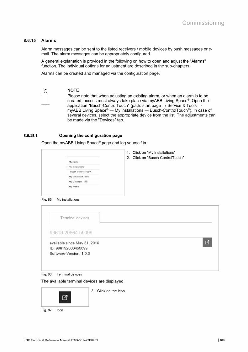
Commissioning
KNX Technical Reference Manual 2CKA001473B8903 │109
8.6.15 Alarms
Alarm messages can be sent to the listed receivers / mobile devices by push messages or e-mail. The alarm messages can be appropriately configured.
A general explanation is provided in the following on how to open and adjust the "Alarms" function. The individual options for adjustment are described in the sub-chapters.
Alarms can be created and managed via the configuration page.
NOTE Please note that when adjusting an existing alarm, or when an alarm is to be created, access must always take place via myABB Living Space®. Open the application "Busch-ControlTouch" (path: start page → Service & Tools → myABB Living Space® → My installations → Busch-ControlTouch®). In case of several devices, select the appropriate device from the list. The adjustments can be made via the "Devices" tab.
8.6.15.1 Opening the configuration page
Open the myABB Living Space® page and log yourself in.
1. Click on "My installations" 2. Click on "Busch-ControlTouch"
Fig. 85: My installations
Fig. 86: Terminal devices
The available terminal devices are displayed.
3. Click on the icon.
Fig. 87: Icon

Commissioning
KNX Technical Reference Manual 2CKA001473B8903 │110
Fig. 88: Configuration page
The configuration page is displayed.
Note The user can archive devices and projects by clicking on the archiving function (arrow pointing to archive). In this way, the device or project will be moved to "Archive" in the menu bar. These will then no longer appear in the list. Archived devices and projects can still be edited by simply selecting the object under "Archive". The object can then be restored by clicking the archiving function (arrow pointing away from archive). – The archiving of the device by an expert includes all of the associated
projects as well. – The archiving of the device by an end user includes all of the associated
profiles as well.
NOTE First a profile must be created, see chapter “Create new profile“ on page 71.
Fig. 89: Profile input field
1. Tap on the appropriate profile in the menu column.
The profile opens.
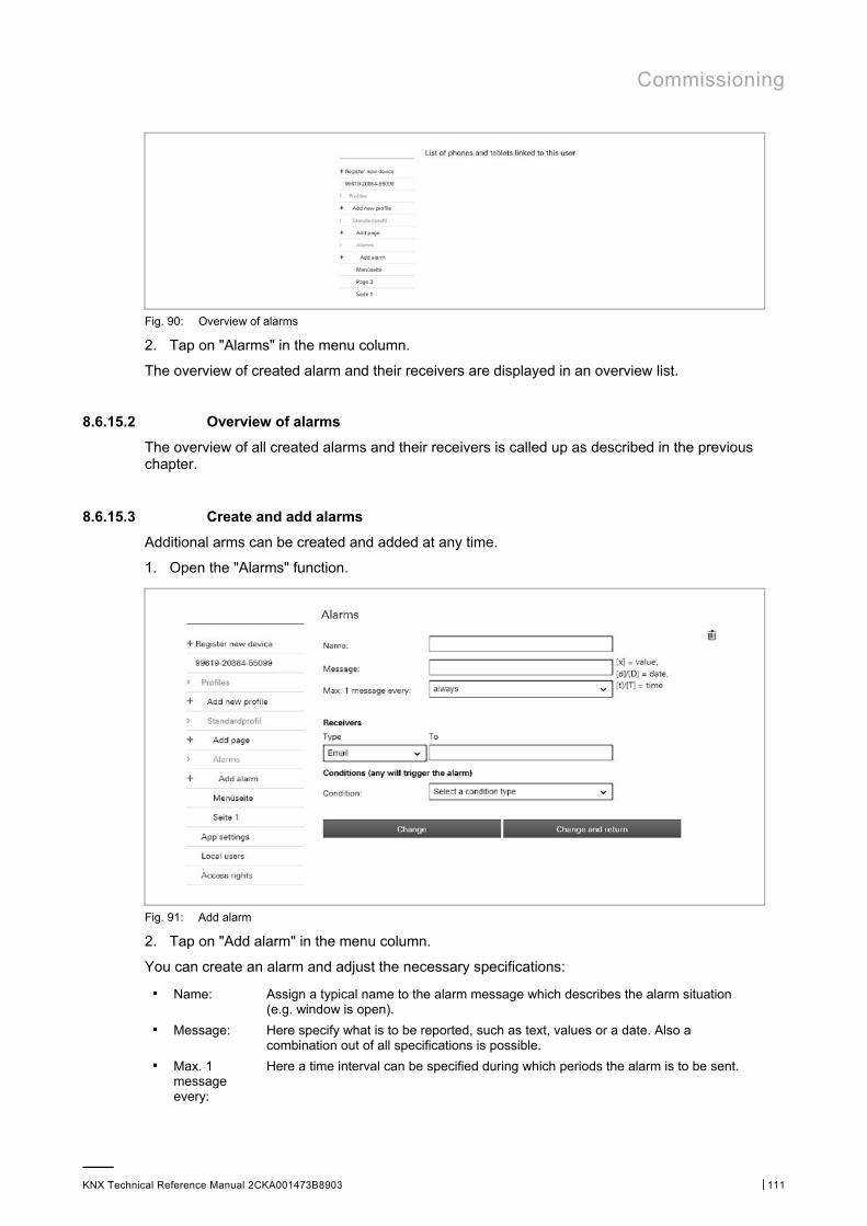
Commissioning
KNX Technical Reference Manual 2CKA001473B8903 │111
Fig. 90: Overview of alarms
2. Tap on "Alarms" in the menu column.
The overview of created alarm and their receivers are displayed in an overview list.
8.6.15.2 Overview of alarms
The overview of all created alarms and their receivers is called up as described in the previous chapter.
8.6.15.3 Create and add alarms
Additional arms can be created and added at any time.
1. Open the "Alarms" function.
Fig. 91: Add alarm
2. Tap on "Add alarm" in the menu column.
You can create an alarm and adjust the necessary specifications:
■ Name: Assign a typical name to the alarm message which describes the alarm situation (e.g. window is open).
■ Message: Here specify what is to be reported, such as text, values or a date. Also a combination out of all specifications is possible.
■ Max. 1 message every:
Here a time interval can be specified during which periods the alarm is to be sent.
Commissioning
KNX Technical Reference Manual 2CKA001473B8903 │112
■ Receivers:
– Type Selection of whether the alarm is sent as e-mail or push notification.
– On For e-mail → entry of e-mail address; for push notification → selection of the mobile device
■ Condition (each one triggers an alarm):
– Condition Fixing the condition that triggers the sending of the alarm (e.g. HTTP trigger). Further settings are necessary depending on the condition. The conditions are specified via the "Trigger" function during the project settings (see chapter “Triggers“ on page 50).
3. Now tap on the "Adjust and back" button.
The overview list opens again. The alarm message with the assigned specifications appears. Also the name of the created alarm appears in the menu column.
8.6.15.4 Adjust alarm
Existing alarms can be adjusted at any time.
1. Open the "Alarms" function.
2. In the menu column tap on the alarm that is to be adjusted.
The alarm opens. You can now adjust the specifications.
3. Then tap on the "Adjust and back" button.
The overview list opens again. The alarm message with the adjusted specifications appears. Also the name of the created alarm appears in the menu column.
8.6.15.5 Delete alarm
Existing alarms can be deleted again at any time.
1. Open the "Alarms" function.
2. In the menu column tap on the alarm that is to be deleted.
The alarm opens.
3. Tap on the rubbish bin icon.
The alarm is deleted.
8.7 Additional settings for the device (configuration page)
Additional settings for the device can be made via the configuration page.
The following sub-chapters explain the setting options for the menu entries in the menu column (exception: send invitation to end customer).
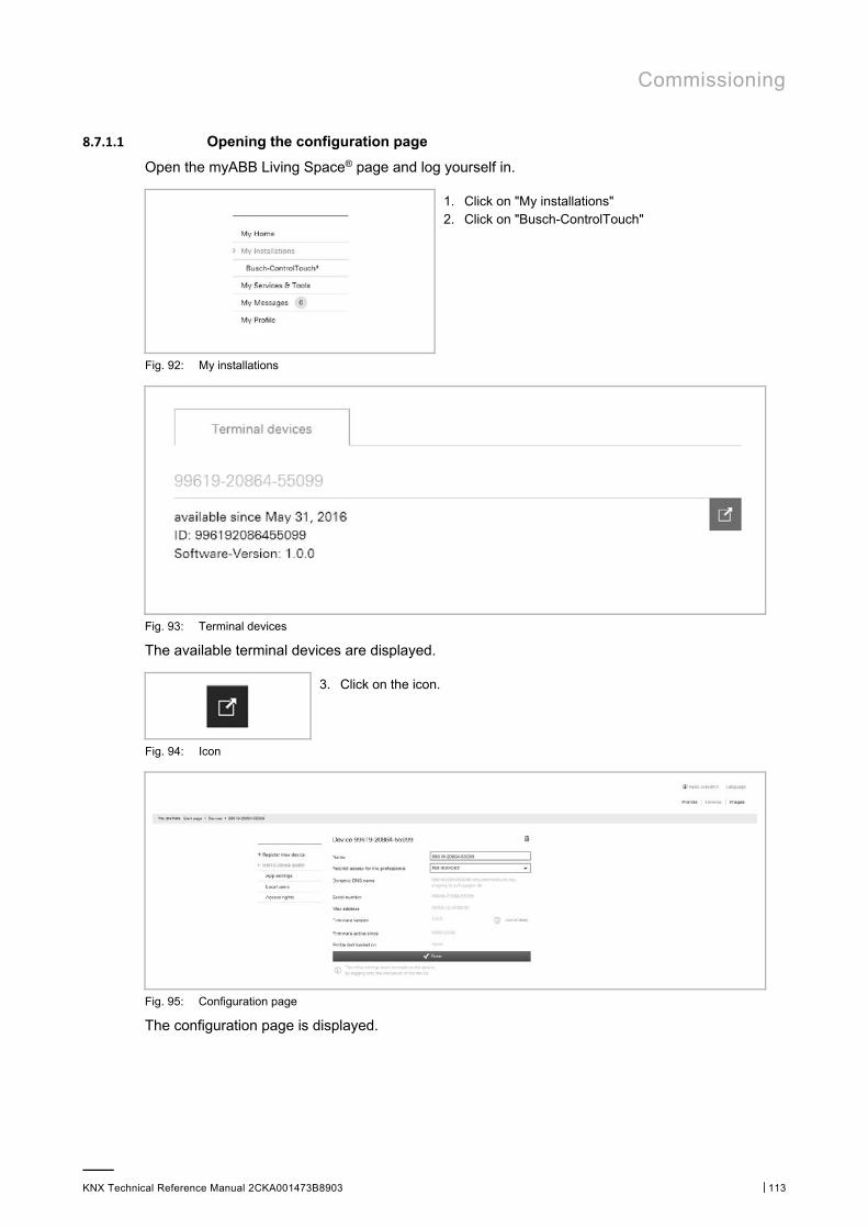
Commissioning
KNX Technical Reference Manual 2CKA001473B8903 │113
8.7.1.1 Opening the configuration page
Open the myABB Living Space® page and log yourself in.
1. Click on "My installations" 2. Click on "Busch-ControlTouch"
Fig. 92: My installations
Fig. 93: Terminal devices
The available terminal devices are displayed.
3. Click on the icon.
Fig. 94: Icon
Fig. 95: Configuration page
The configuration page is displayed.
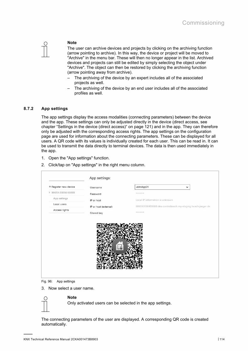
Commissioning
KNX Technical Reference Manual 2CKA001473B8903 │114
Note The user can archive devices and projects by clicking on the archiving function (arrow pointing to archive). In this way, the device or project will be moved to "Archive" in the menu bar. These will then no longer appear in the list. Archived devices and projects can still be edited by simply selecting the object under "Archive". The object can then be restored by clicking the archiving function (arrow pointing away from archive). – The archiving of the device by an expert includes all of the associated
projects as well. – The archiving of the device by an end user includes all of the associated
profiles as well.
8.7.2 App settings
The app settings display the access modalities (connecting parameters) between the device and the app. These settings can only be adjusted directly in the device (direct access, see chapter “Settings in the device (direct access)“ on page 121) and in the app. They can therefore only be adjusted with the corresponding access rights. The app settings on the configuration page are used for information about the connecting parameters. These can be displayed for all users. A QR code with its values is individually created for each user. This can be read in. It can be used to transmit the data directly to terminal devices. The data is then used immediately in the app.
1. Open the "App settings" function.
2. Click/tap on "App settings" in the right menu column.
Fig. 96: App settings
3. Now select a user name.
Note Only activated users can be selected in the app settings.
The connecting parameters of the user are displayed. A corresponding QR code is created automatically.
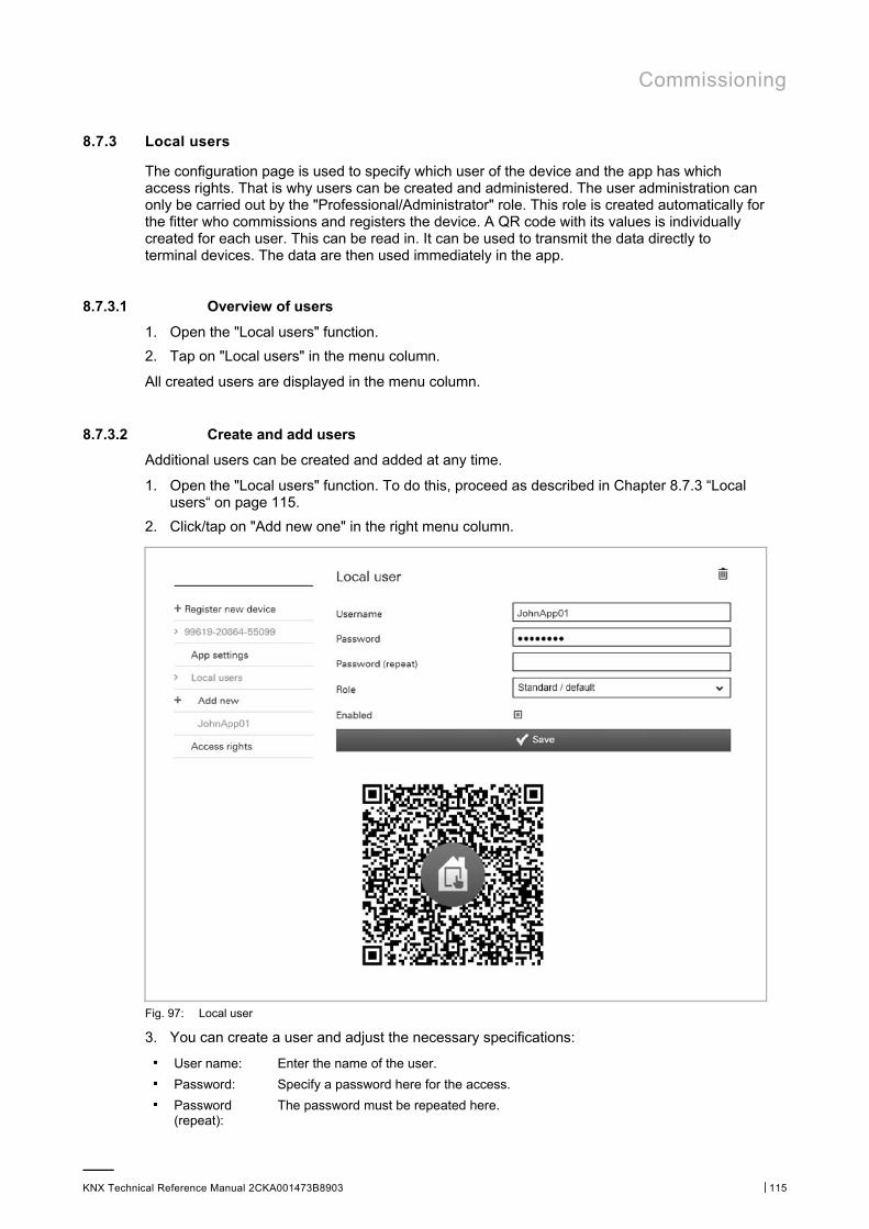
Commissioning
KNX Technical Reference Manual 2CKA001473B8903 │115
8.7.3 Local users
The configuration page is used to specify which user of the device and the app has which access rights. That is why users can be created and administered. The user administration can only be carried out by the "Professional/Administrator" role. This role is created automatically for the fitter who commissions and registers the device. A QR code with its values is individually created for each user. This can be read in. It can be used to transmit the data directly to terminal devices. The data are then used immediately in the app.
8.7.3.1 Overview of users
1. Open the "Local users" function.
2. Tap on "Local users" in the menu column.
All created users are displayed in the menu column.
8.7.3.2 Create and add users
Additional users can be created and added at any time.
1. Open the "Local users" function. To do this, proceed as described in Chapter 8.7.3 “Local users“ on page 115.
2. Click/tap on "Add new one" in the right menu column.
Fig. 97: Local user
3. You can create a user and adjust the necessary specifications:
■ User name: Enter the name of the user. ■ Password: Specify a password here for the access. ■ Password
(repeat): The password must be repeated here.
Commissioning
KNX Technical Reference Manual 2CKA001473B8903 │116
■ Role: Here the role which has been specified under the "Access rights" function can be selected (with the exception of Professional/Administrator → this role has been fixed and cannot be changed). A role includes a package of access rights.
■ Activated: The user can also be deactivated after being created. The user therefore does not need to be immediately deleted, for example. Only activated users can be selected in the app settings.
4. Now click/tap on the "Save" button.
The newly created user is added in the menu column.
Note A QR code with its values is individually created for each activated user. This can be read in. It can be used to transmit the data directly to terminal devices. The data is then used immediately in the app.
8.7.3.3 Adjust users
Existing users can be adjusted at any time.
1. Open the "Local users" function.
2. In the menu column tap on the user that is to be adjusted.
The user opens. You can now adjust the specifications.
3. And finally, tap on the "Save" button.
8.7.3.4 Delete users
Existing users can be deleted again at any time.
1. Open the "Local users" function.
Proceed as described in Chapter 8.7.3 “Local users“ on page 115.
2. In the menu column click/tap on the user that is to be deleted.
The user opens.
3. Click/tap on the rubbish bin icon.
The user is deleted.
8.7.4 Access rights (roles)
So-called "Roles" can be created and managed via the configuration page. A role includes a package of access rights. These roles in turn can be assigned to a user. The administration of the roles can only be carried out by the "Professional/Administrator" role. This role is created automatically for the fitter who commissions and registers the device. The "Professional/Administrator" role is fixed automatically and cannot be changed.
8.7.4.1 Overview of roles
1. Open the "Access rights" function.
2. Tap on "Access rights" in the menu column.
All created roles are displayed in the menu column.
Note Users with limited access rights will receive a warning in the app if they attempt to perform an action for which they do not have the necessary access rights.
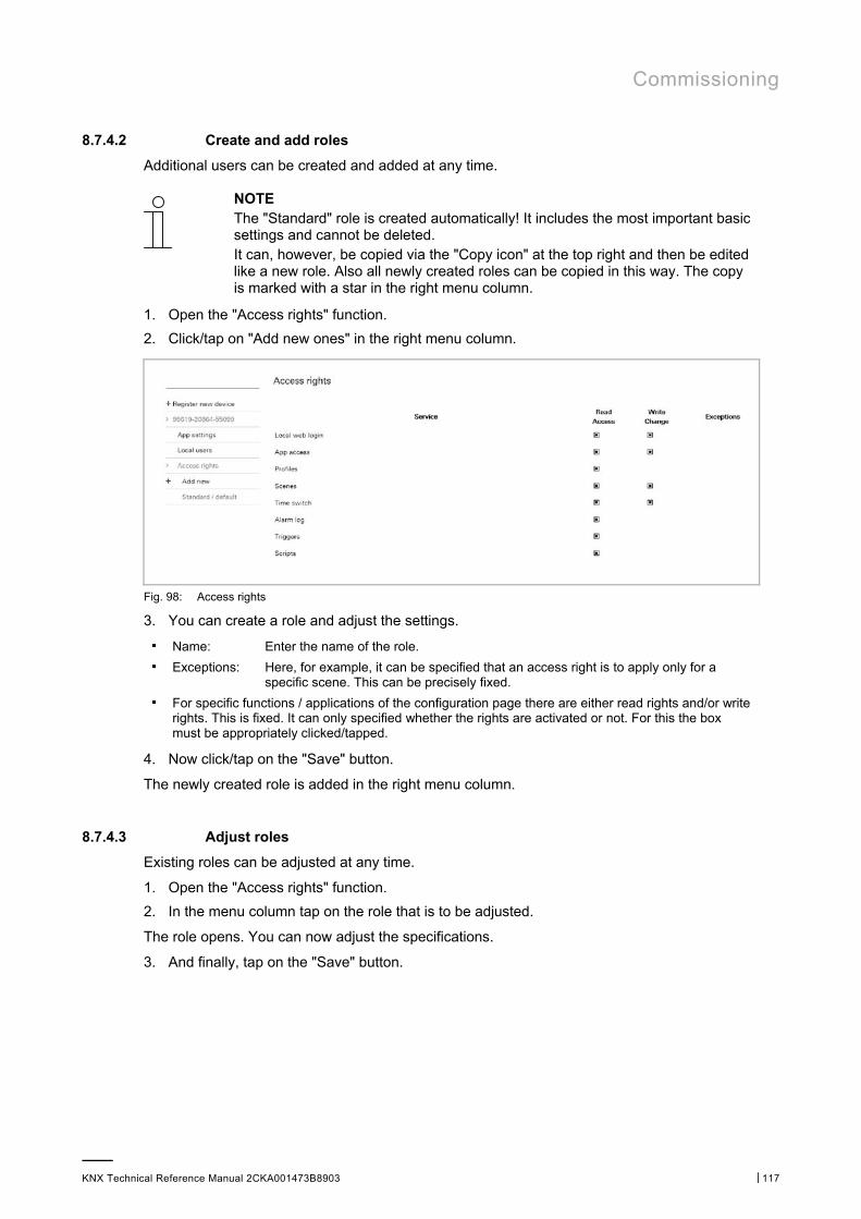
Commissioning
KNX Technical Reference Manual 2CKA001473B8903 │117
8.7.4.2 Create and add roles
Additional users can be created and added at any time.
NOTE The "Standard" role is created automatically! It includes the most important basic settings and cannot be deleted. It can, however, be copied via the "Copy icon" at the top right and then be edited like a new role. Also all newly created roles can be copied in this way. The copy is marked with a star in the right menu column.
1. Open the "Access rights" function.
2. Click/tap on "Add new ones" in the right menu column.
Fig. 98: Access rights
3. You can create a role and adjust the settings.
■ Name: Enter the name of the role. ■ Exceptions: Here, for example, it can be specified that an access right is to apply only for a
specific scene. This can be precisely fixed. ■ For specific functions / applications of the configuration page there are either read rights and/or write
rights. This is fixed. It can only specified whether the rights are activated or not. For this the box must be appropriately clicked/tapped.
4. Now click/tap on the "Save" button.
The newly created role is added in the right menu column.
8.7.4.3 Adjust roles
Existing roles can be adjusted at any time.
1. Open the "Access rights" function.
2. In the menu column tap on the role that is to be adjusted.
The role opens. You can now adjust the specifications.
3. And finally, tap on the "Save" button.
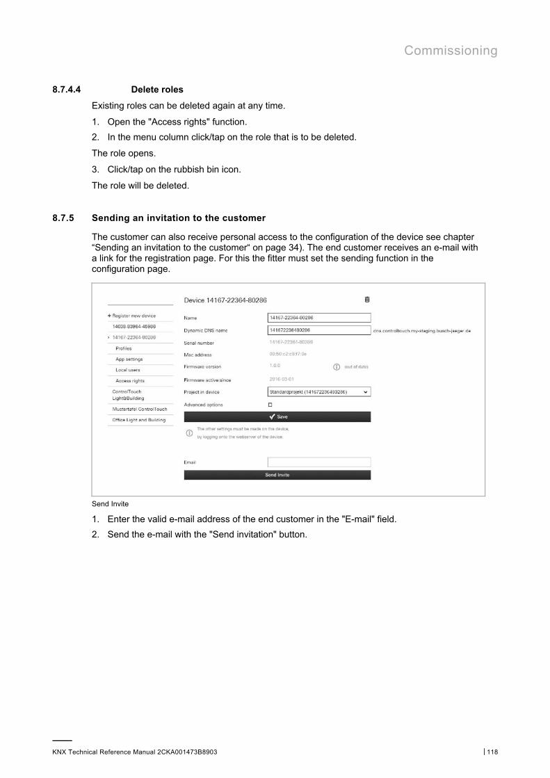
Commissioning
KNX Technical Reference Manual 2CKA001473B8903 │118
8.7.4.4 Delete roles
Existing roles can be deleted again at any time.
1. Open the "Access rights" function.
2. In the menu column click/tap on the role that is to be deleted.
The role opens.
3. Click/tap on the rubbish bin icon.
The role will be deleted.
8.7.5 Sending an invitation to the customer
The customer can also receive personal access to the configuration of the device see chapter “Sending an invitation to the customer“ on page 34). The end customer receives an e-mail with a link for the registration page. For this the fitter must set the sending function in the configuration page.
Send Invite
1. Enter the valid e-mail address of the end customer in the "E-mail" field.
2. Send the e-mail with the "Send invitation" button.

Commissioning
KNX Technical Reference Manual 2CKA001473B8903 │119
8.7.6 Logging out a specialist's account Confirming the log-in of a specialist
From the configuration page of the device, the end user can force the account of a specialist to be logged out of a device (but only if the end user and the specialist are not the same person). When the device is logged off, the project is copied. This means that the specialist who created the project can still view it, and that a new specialist who is registering their own device can still access it.
When performing a forced log-out, or if the device is no longer logged in by an expert, the end user has the option of deactivating the registration of any specialists (see "Deregister" button). The end user can also reverse the effect of this function if required.
Note If the specialist intends to log on to a blocked device, the specialist will receive a notification that the device was blocked by the end user.
Fig. 99: Restricting access to specialists
1. Select the corresponding restriction.
2. Confirm with the "Save" button.
3. The "Deregister" button is used to perform the deregistration.
8.7.7 Creating a widget function for iOS
The iOS app supports widgets. The profile widget can be activated using the "iOS Widget" function.
The first button of the widget is always the link for opening the app.
Additional buttons can be added:
– Send value (identical to button row)
– Blind (up/down + status)
– Switch (on/off + status)
– Call scenario (no status)
– Send command (uPnP, no status)
– Placeholder
The widget can be activated in the iOS device. Then the symbols will be loaded as they were configured in the profile. The widget is connected and the buttons can be used.
Note Please note that the response time is somewhat slower than if only the ControlTouch app is used.
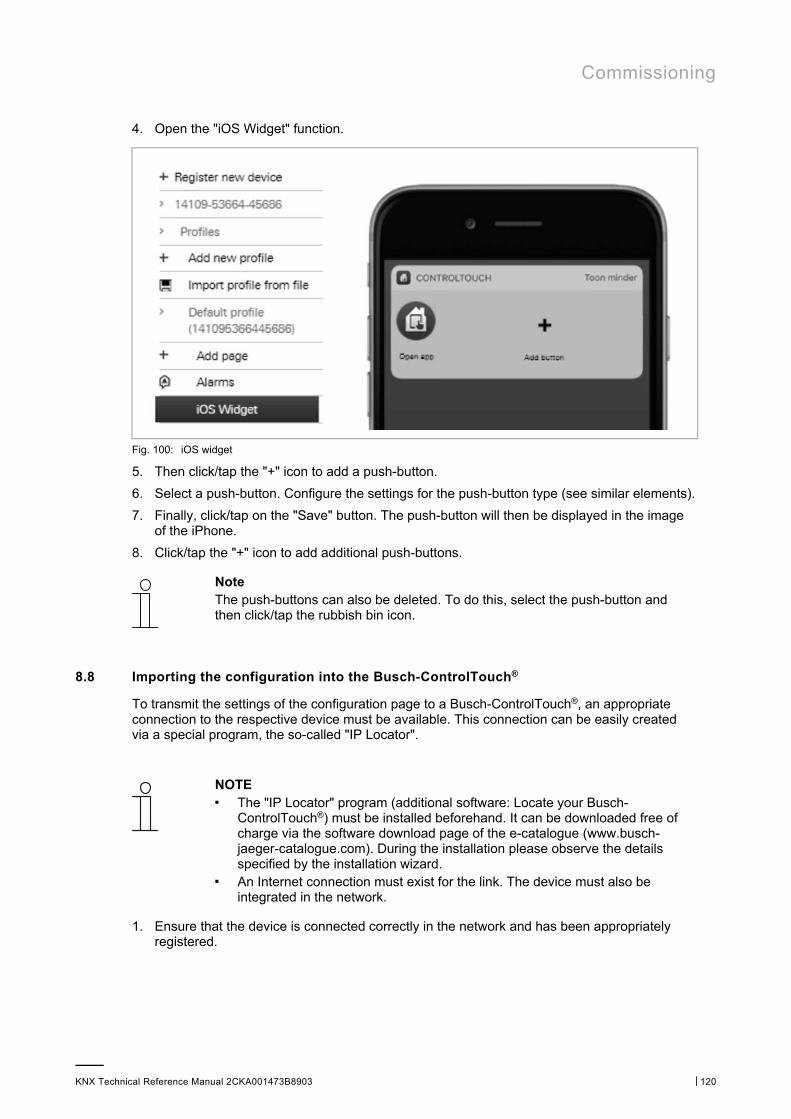
Commissioning
KNX Technical Reference Manual 2CKA001473B8903 │120
4. Open the "iOS Widget" function.
Fig. 100: iOS widget
5. Then click/tap the "+" icon to add a push-button.
6. Select a push-button. Configure the settings for the push-button type (see similar elements).
7. Finally, click/tap on the "Save" button. The push-button will then be displayed in the image of the iPhone.
8. Click/tap the "+" icon to add additional push-buttons.
Note The push-buttons can also be deleted. To do this, select the push-button and then click/tap the rubbish bin icon.
8.8 Importing the configuration into the Busch-ControlTouch®
To transmit the settings of the configuration page to a Busch-ControlTouch®, an appropriate connection to the respective device must be available. This connection can be easily created via a special program, the so-called "IP Locator".
NOTE ■ The "IP Locator" program (additional software: Locate your Busch-
ControlTouch®) must be installed beforehand. It can be downloaded free of charge via the software download page of the e-catalogue (www.busch-jaeger-catalogue.com). During the installation please observe the details specified by the installation wizard.
■ An Internet connection must exist for the link. The device must also be integrated in the network.
1. Ensure that the device is connected correctly in the network and has been appropriately registered.
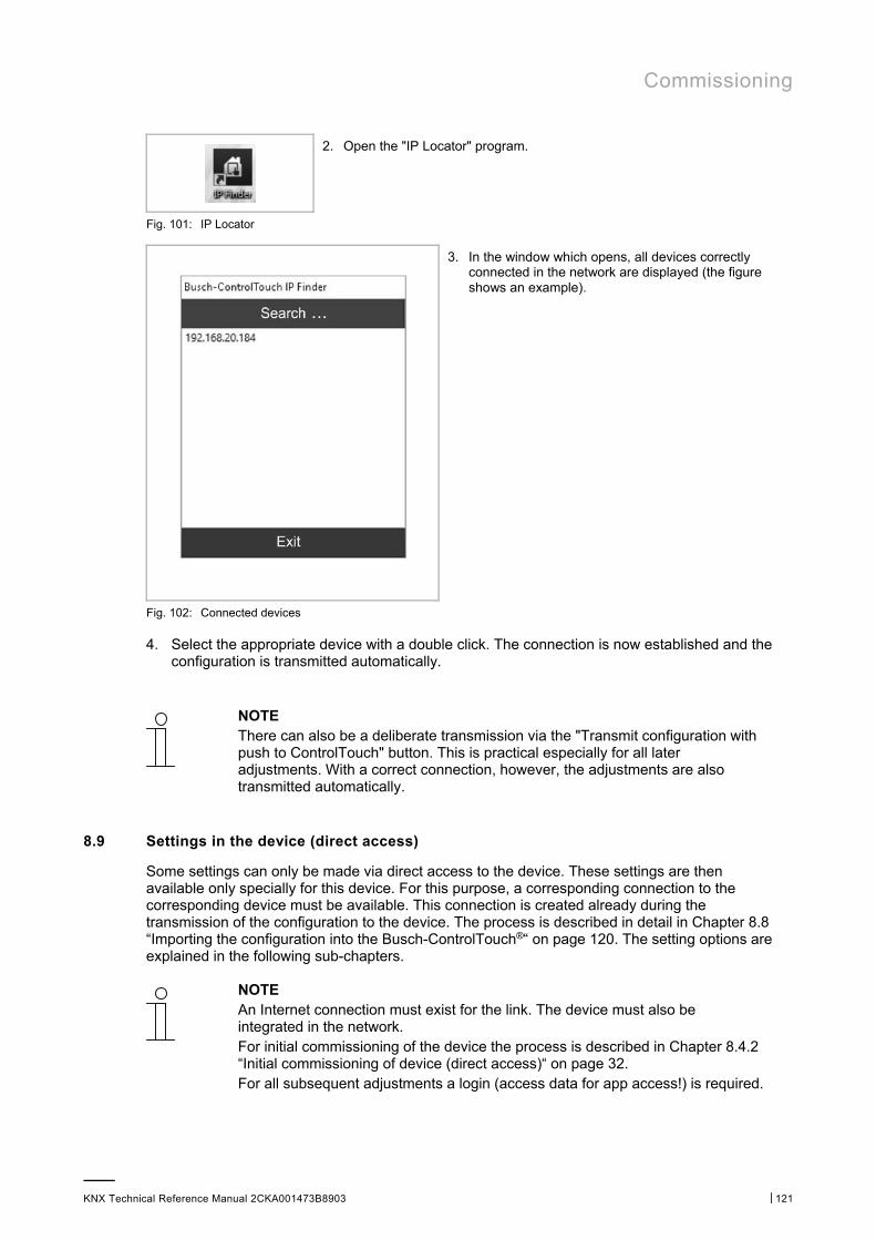
Commissioning
KNX Technical Reference Manual 2CKA001473B8903 │121
2. Open the "IP Locator" program.
Fig. 101: IP Locator
3. In the window which opens, all devices correctly connected in the network are displayed (the figure shows an example).
Fig. 102: Connected devices
4. Select the appropriate device with a double click. The connection is now established and the configuration is transmitted automatically.
NOTE There can also be a deliberate transmission via the "Transmit configuration with push to ControlTouch" button. This is practical especially for all later adjustments. With a correct connection, however, the adjustments are also transmitted automatically.
8.9 Settings in the device (direct access)
Some settings can only be made via direct access to the device. These settings are then available only specially for this device. For this purpose, a corresponding connection to the corresponding device must be available. This connection is created already during the transmission of the configuration to the device. The process is described in detail in Chapter 8.8 “Importing the configuration into the Busch-ControlTouch®“ on page 120. The setting options are explained in the following sub-chapters.
NOTE An Internet connection must exist for the link. The device must also be integrated in the network. For initial commissioning of the device the process is described in Chapter 8.4.2 “Initial commissioning of device (direct access)“ on page 32. For all subsequent adjustments a login (access data for app access!) is required.
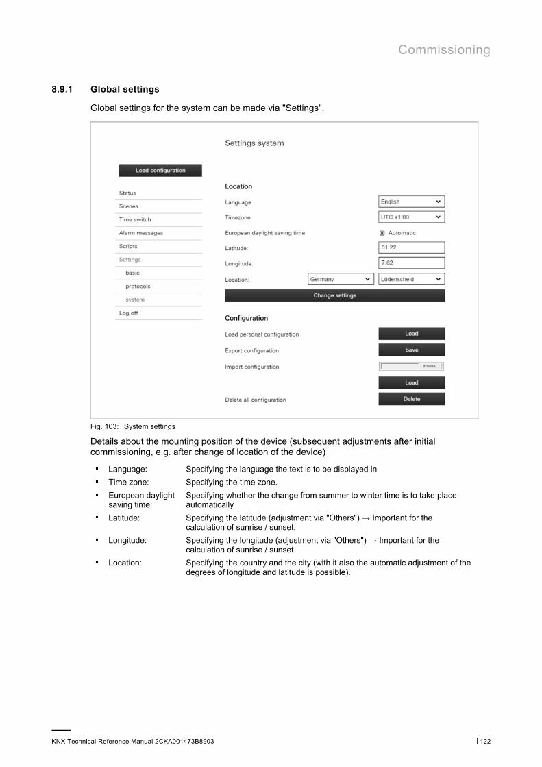
Commissioning
KNX Technical Reference Manual 2CKA001473B8903 │122
8.9.1 Global settings
Global settings for the system can be made via "Settings".
Fig. 103: System settings
Details about the mounting position of the device (subsequent adjustments after initial commissioning, e.g. after change of location of the device)
■ Language: Specifying the language the text is to be displayed in ■ Time zone: Specifying the time zone. ■ European daylight
saving time: Specifying whether the change from summer to winter time is to take place automatically
■ Latitude: Specifying the latitude (adjustment via "Others") → Important for the calculation of sunrise / sunset.
■ Longitude: Specifying the longitude (adjustment via "Others") → Important for the calculation of sunrise / sunset.
■ Location: Specifying the country and the city (with it also the automatic adjustment of the degrees of longitude and latitude is possible).
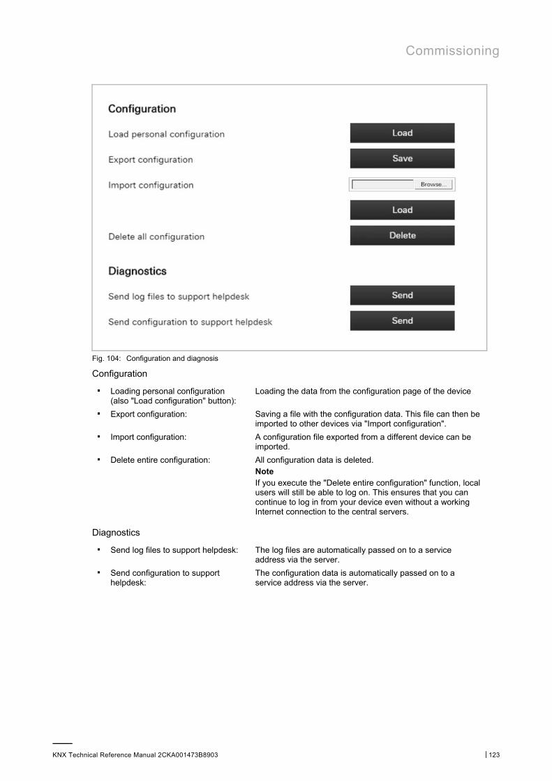
Commissioning
KNX Technical Reference Manual 2CKA001473B8903 │123
Fig. 104: Configuration and diagnosis
Configuration
■ Loading personal configuration (also "Load configuration" button):
Loading the data from the configuration page of the device
■ Export configuration: Saving a file with the configuration data. This file can then be imported to other devices via "Import configuration".
■ Import configuration: A configuration file exported from a different device can be imported.
■ Delete entire configuration: All configuration data is deleted. Note If you execute the "Delete entire configuration" function, local users will still be able to log on. This ensures that you can continue to log in from your device even without a working Internet connection to the central servers.
Diagnostics
■ Send log files to support helpdesk: The log files are automatically passed on to a service address via the server.
■ Send configuration to support helpdesk:
The configuration data is automatically passed on to a service address via the server.
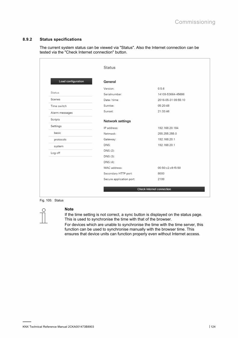
Commissioning
KNX Technical Reference Manual 2CKA001473B8903 │124
8.9.2 Status specifications
The current system status can be viewed via "Status". Also the Internet connection can be tested via the "Check Internet connection" button.
Fig. 105: Status
Note If the time setting is not correct, a sync button is displayed on the status page. This is used to synchronise the time with that of the browser. For devices which are unable to synchronise the time with the time server, this function can be used to synchronise manually with the browser time. This ensures that device units can function properly even without Internet access.
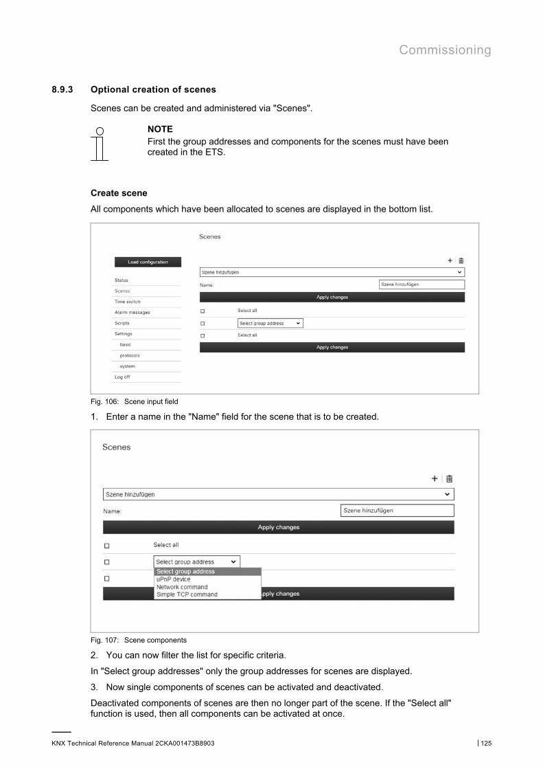
Commissioning
KNX Technical Reference Manual 2CKA001473B8903 │125
8.9.3 Optional creation of scenes
Scenes can be created and administered via "Scenes".
NOTE First the group addresses and components for the scenes must have been created in the ETS.
Create scene
All components which have been allocated to scenes are displayed in the bottom list.
Fig. 106: Scene input field
1. Enter a name in the "Name" field for the scene that is to be created.
Fig. 107: Scene components
2. You can now filter the list for specific criteria.
In "Select group addresses" only the group addresses for scenes are displayed.
3. Now single components of scenes can be activated and deactivated.
Deactivated components of scenes are then no longer part of the scene. If the "Select all" function is used, then all components can be activated at once.
Commissioning
KNX Technical Reference Manual 2CKA001473B8903 │126
4. Components of scenes can also be deleted via the rubbish bin icon.
5. Save the adjustments via the "Apply adjustments" button.
6. Then all the activated components of this scene are displayed.
7. Now additional scenes can be created according to this concept via the "+" button.
Adjust scene
1. Use the arrow to select the scene to be adjusted.
2. Now all the components of this scene are displayed.
3. You can now filter the list for specific criteria. In "Select group addresses" only the group addresses for scenes are displayed.
4. Now single components of scenes can be activated and deactivated. Deactivated components of scenes are then no longer part of the scene. If the "Select all" function is used, then all components can be activated at once.
5. Components of scenes can also be deleted via the rubbish bin icon.
6. Save the adjustments via the "Apply adjustments" button.
Delete scene completely
1. Use the arrow to select the scene to be deleted.
2. Delete the scene via the rubbish bin icon.
3. Save the adjustments via the "Apply adjustments" button.
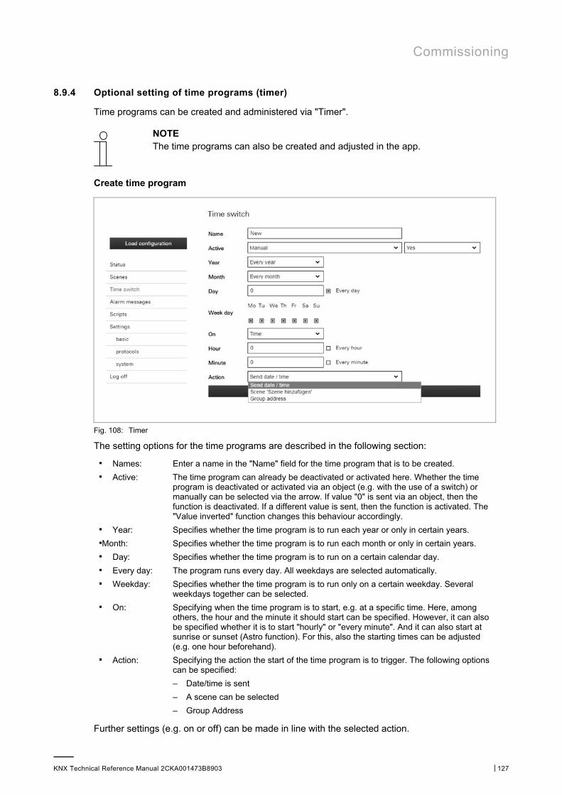
Commissioning
KNX Technical Reference Manual 2CKA001473B8903 │127
8.9.4 Optional setting of time programs (timer)
Time programs can be created and administered via "Timer".
NOTE The time programs can also be created and adjusted in the app.
Create time program
Fig. 108: Timer
The setting options for the time programs are described in the following section:
■ Names: Enter a name in the "Name" field for the time program that is to be created. ■ Active: The time program can already be deactivated or activated here. Whether the time
program is deactivated or activated via an object (e.g. with the use of a switch) or manually can be selected via the arrow. If value "0" is sent via an object, then the function is deactivated. If a different value is sent, then the function is activated. The "Value inverted" function changes this behaviour accordingly.
■ Year: Specifies whether the time program is to run each year or only in certain years. ■Month: Specifies whether the time program is to run each month or only in certain years. ■ Day: Specifies whether the time program is to run on a certain calendar day. ■ Every day: The program runs every day. All weekdays are selected automatically. ■ Weekday: Specifies whether the time program is to run only on a certain weekday. Several
weekdays together can be selected. ■ On: Specifying when the time program is to start, e.g. at a specific time. Here, among
others, the hour and the minute it should start can be specified. However, it can also be specified whether it is to start "hourly" or "every minute". And it can also start at sunrise or sunset (Astro function). For this, also the starting times can be adjusted (e.g. one hour beforehand).
■ Action: Specifying the action the start of the time program is to trigger. The following options can be specified:
– Date/time is sent
– A scene can be selected
– Group Address
Further settings (e.g. on or off) can be made in line with the selected action.

Commissioning
KNX Technical Reference Manual 2CKA001473B8903 │128
1. And finally the time program is saved with the "On" button.
The time program appears in the overview list.
Further time programs can be created via the "+" button.
Adjust time program
The time programs can be selected in the overview list and adjusted accordingly.
The following adjustments can be made directly in the overview list.
– Deactivation/activation
– Adjustment of start times (also for sunrise or sunset)
– Selection of weekdays
The time program can be called up and adjustments made via the tool icon.
1. And finally the time program is saved with the "On" button.
Delete time program
The time programs can be deleted in the overview list via the rubbish bin icon.

Commissioning
KNX Technical Reference Manual 2CKA001473B8903 │129
8.9.5 Proxy settings – Internet connection (Port allocation)
The proxy settings can be changed via "Settings - Basis".
Note The proxy settings should be adjusted only when its is absolutely essential!
Fig. 109: Network settings
The DHCP function can be deactivated/activated here. Also additional network settings can be made here. For example, a different port can be allocated here. Port "2199" is the secure application port used for connecting the device to the Internet. The device can also be operated via the Internet. The port is specified already in advance. The adjustments must be stored via the "Apply" button.
HTTPS access for local settings
In addition to HTTP (ports 80 and 8000), HTTPS is also available. When starting after an update, the device unit automatically generates a self-signed certificate and facilitates access to HTTPS (standard port 443). Before access is granted, the self-signed certificate must be accepted manually in most browsers.
In "Advanced network settings", users can define whether they wish to use HTTP, HTTPS or both protocols.
Fig. 110: Advance network settings
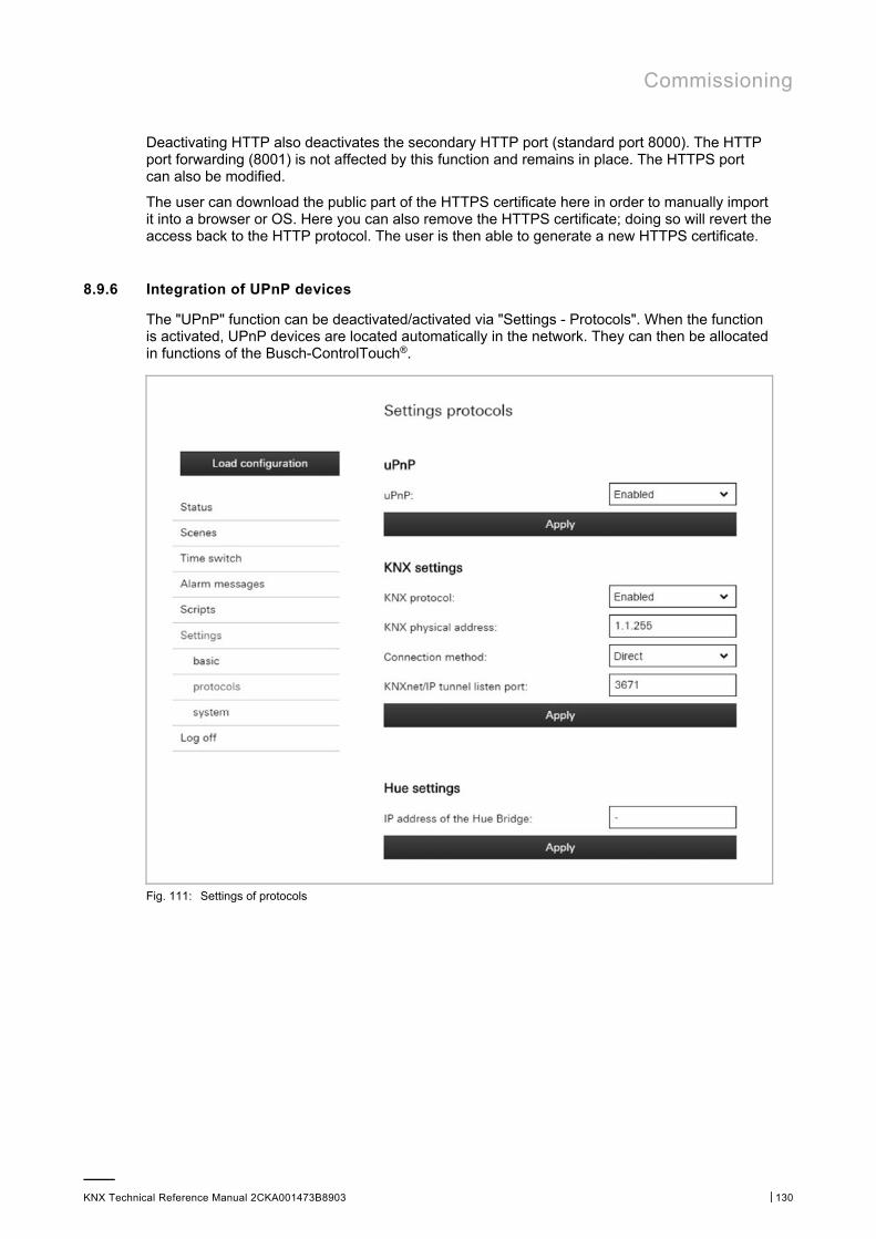
Commissioning
KNX Technical Reference Manual 2CKA001473B8903 │130
Deactivating HTTP also deactivates the secondary HTTP port (standard port 8000). The HTTP port forwarding (8001) is not affected by this function and remains in place. The HTTPS port can also be modified.
The user can download the public part of the HTTPS certificate here in order to manually import it into a browser or OS. Here you can also remove the HTTPS certificate; doing so will revert the access back to the HTTP protocol. The user is then able to generate a new HTTPS certificate.
8.9.6 Integration of UPnP devices
The "UPnP" function can be deactivated/activated via "Settings - Protocols". When the function is activated, UPnP devices are located automatically in the network. They can then be allocated in functions of the Busch-ControlTouch®.
Fig. 111: Settings of protocols
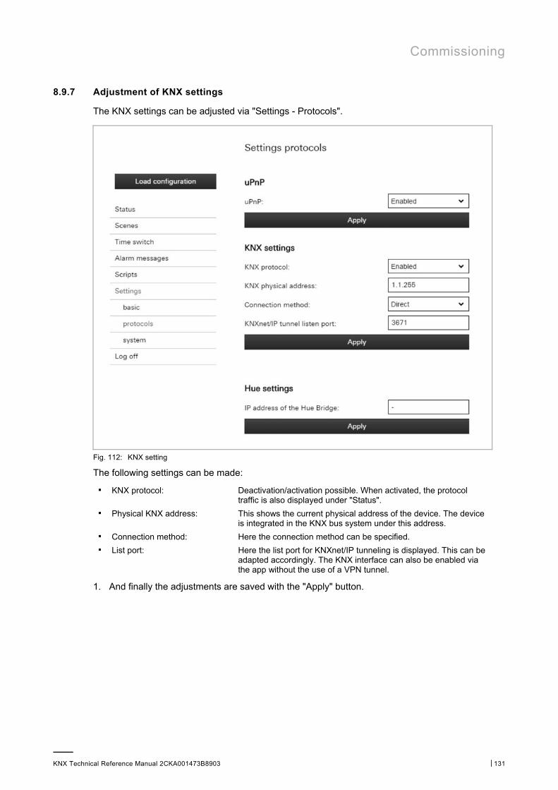
Commissioning
KNX Technical Reference Manual 2CKA001473B8903 │131
8.9.7 Adjustment of KNX settings
The KNX settings can be adjusted via "Settings - Protocols".
Fig. 112: KNX setting
The following settings can be made:
■ KNX protocol: Deactivation/activation possible. When activated, the protocol traffic is also displayed under "Status".
■ Physical KNX address: This shows the current physical address of the device. The device is integrated in the KNX bus system under this address.
■ Connection method: Here the connection method can be specified. ■ List port: Here the list port for KNXnet/IP tunneling is displayed. This can be
adapted accordingly. The KNX interface can also be enabled via the app without the use of a VPN tunnel.
1. And finally the adjustments are saved with the "Apply" button.
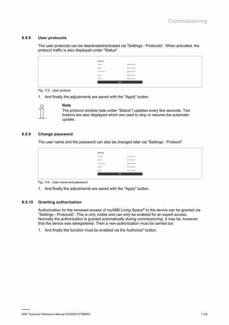
Commissioning
KNX Technical Reference Manual 2CKA001473B8903 │132
8.9.8 User protocols
The user protocols can be deactivated/activated via "Settings - Protocols". When activated, the protocol traffic is also displayed under "Status".
Fig. 113: User protocol
1. And finally the adjustments are saved with the "Apply" button.
Note The protocol window (see under "Status") updates every few seconds. Two buttons are also displayed which are used to stop or resume the automatic update.
8.9.9 Change password
The user name and the password can also be changed later via "Settings - Protocol".
Fig. 114: User name and password
1. And finally the adjustments are saved with the "Apply" button.
8.9.10 Granting authorization
Authorization for the renewed access of myABB Living Space® to the device can be granted via "Settings - Protocols". This is only visible and can only be enabled for an expert access. Normally the authorization is granted automatically during commissioning. It may be, however, that the device was deregistered. Then a new authorization must be carried out.
1. And finally the function must be enabled via the Authorize" button.
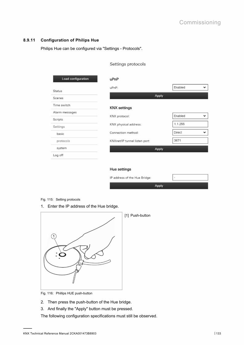
Commissioning
KNX Technical Reference Manual 2CKA001473B8903 │133
8.9.11 Configuration of Philips Hue
Philips Hue can be configured via "Settings - Protocols".
Fig. 115: Setting protocols
1. Enter the IP address of the Hue bridge.
[1] Push-button
Fig. 116: Phillips HUE push-button
2. Then press the push-button of the Hue bridge.
3. And finally the "Apply" button must be pressed.
The following configuration specifications must still be observed.
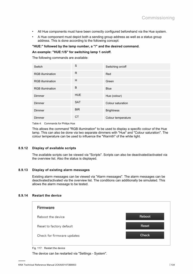
Commissioning
KNX Technical Reference Manual 2CKA001473B8903 │134
■ All Hue components must have been correctly configured beforehand via the Hue system. ■ A Hue component must depict both a sending group address as well as a status group
address. This is done according to the following concept:
"HUE:" followed by the lamp number, a "/" and the desired command.
An example: "HUE:1/S" for switching lamp 1 on/off.
The following commands are available:
Switch S Switching on/off
RGB illumination R Red
RGB illumination H Green
RGB illumination B Blue
Dimmer HUE Hue (colour)
Dimmer SAT Colour saturation
Dimmer BIR Brightness
Dimmer CT Colour temperature
Table 4: Commands for Philips Hue
This allows the command "RGB illumination" to be used to display a specific colour of the Hue lamp. This can also be done via two separate dimmers with "Hue" and "Colour saturation". The colour temperature can be used to influence the "Warmth" of the white light.
8.9.12 Display of available scripts
The available scripts can be viewed via "Scripts". Scripts can also be deactivated/activated via the overview list. Also the status is displayed.
8.9.13 Display of existing alarm messages
Existing alarm messages can be viewed via "Alarm messages". The alarm messages can be deactivated/activated via the overview list. The conditions can additionally be simulated. This allows the alarm message to be tested.
8.9.14 Restart the device
Fig. 117: Restart the device
The device can be restarted via "Settings - System".
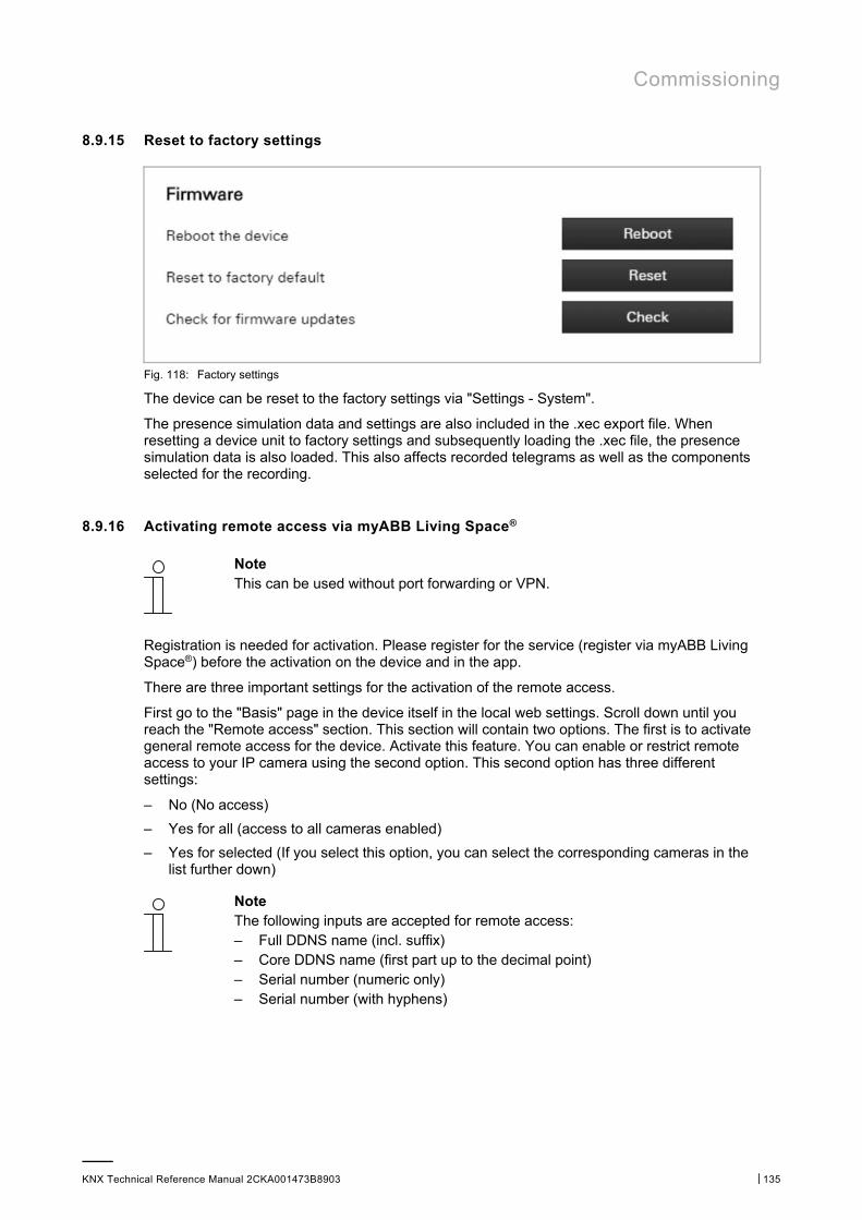
Commissioning
KNX Technical Reference Manual 2CKA001473B8903 │135
8.9.15 Reset to factory settings
Fig. 118: Factory settings
The device can be reset to the factory settings via "Settings - System".
The presence simulation data and settings are also included in the .xec export file. When resetting a device unit to factory settings and subsequently loading the .xec file, the presence simulation data is also loaded. This also affects recorded telegrams as well as the components selected for the recording.
8.9.16 Activating remote access via myABB Living Space®
Note This can be used without port forwarding or VPN.
Registration is needed for activation. Please register for the service (register via myABB Living Space®) before the activation on the device and in the app.
There are three important settings for the activation of the remote access.
First go to the "Basis" page in the device itself in the local web settings. Scroll down until you reach the "Remote access" section. This section will contain two options. The first is to activate general remote access for the device. Activate this feature. You can enable or restrict remote access to your IP camera using the second option. This second option has three different settings:
– No (No access)
– Yes for all (access to all cameras enabled)
– Yes for selected (If you select this option, you can select the corresponding cameras in the list further down)
Note The following inputs are accepted for remote access: – Full DDNS name (incl. suffix) – Core DDNS name (first part up to the decimal point) – Serial number (numeric only) – Serial number (with hyphens)
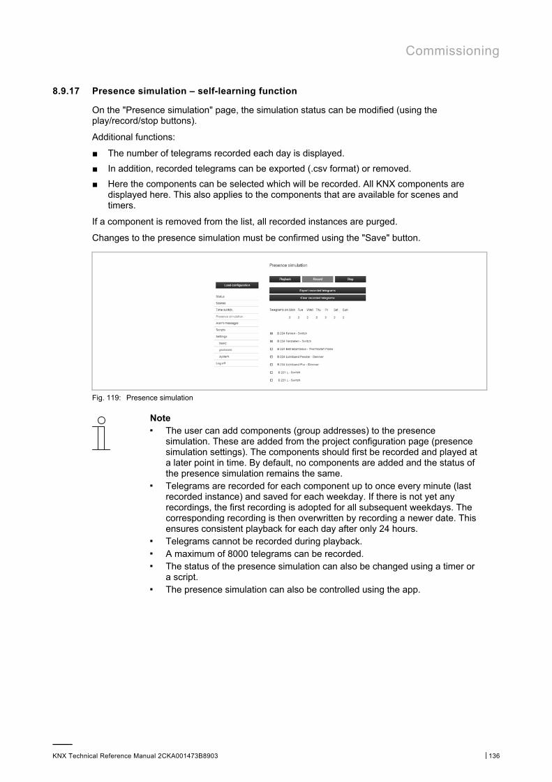
Commissioning
KNX Technical Reference Manual 2CKA001473B8903 │136
8.9.17 Presence simulation – self-learning function
On the "Presence simulation" page, the simulation status can be modified (using the play/record/stop buttons).
Additional functions:
■ The number of telegrams recorded each day is displayed.
■ In addition, recorded telegrams can be exported (.csv format) or removed.
■ Here the components can be selected which will be recorded. All KNX components are displayed here. This also applies to the components that are available for scenes and timers.
If a component is removed from the list, all recorded instances are purged.
Changes to the presence simulation must be confirmed using the "Save" button.
Fig. 119: Presence simulation
Note ■ The user can add components (group addresses) to the presence
simulation. These are added from the project configuration page (presence simulation settings). The components should first be recorded and played at a later point in time. By default, no components are added and the status of the presence simulation remains the same.
■ Telegrams are recorded for each component up to once every minute (last recorded instance) and saved for each weekday. If there is not yet any recordings, the first recording is adopted for all subsequent weekdays. The corresponding recording is then overwritten by recording a newer date. This ensures consistent playback for each day after only 24 hours.
■ Telegrams cannot be recorded during playback. ■ A maximum of 8000 telegrams can be recorded. ■ The status of the presence simulation can also be changed using a timer or
a script. ■ The presence simulation can also be controlled using the app.
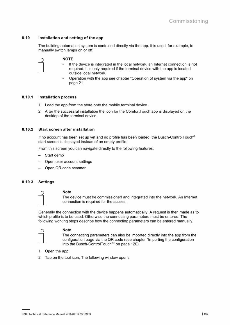
Commissioning
KNX Technical Reference Manual 2CKA001473B8903 │137
8.10 Installation and setting of the app
The building automation system is controlled directly via the app. It is used, for example, to manually switch lamps on or off.
NOTE ■ If the device is integrated in the local network, an Internet connection is not
required. It is only required if the terminal device with the app is located outside local network.
■ Operation with the app see chapter “Operation of system via the app“ on page 21.
8.10.1 Installation process
1. Load the app from the store onto the mobile terminal device.
2. After the successful installation the icon for the ComfortTouch app is displayed on the desktop of the terminal device.
8.10.2 Start screen after installation
If no account has been set up yet and no profile has been loaded, the Busch-ControlTouch® start screen is displayed instead of an empty profile.
From this screen you can navigate directly to the following features:
– Start demo
– Open user account settings
– Open QR code scanner
8.10.3 Settings
Note The device must be commissioned and integrated into the network. An Internet connection is required for the access.
Generally the connection with the device happens automatically. A request is then made as to which profile is to be used. Otherwise the connecting parameters must be entered. The following working steps describe how the connecting parameters can be entered manually.
Note The connecting parameters can also be imported directly into the app from the configuration page via the QR code (see chapter “Importing the configuration into the Busch-ControlTouch®“ on page 120)
1. Open the app.
2. Tap on the tool icon. The following window opens:
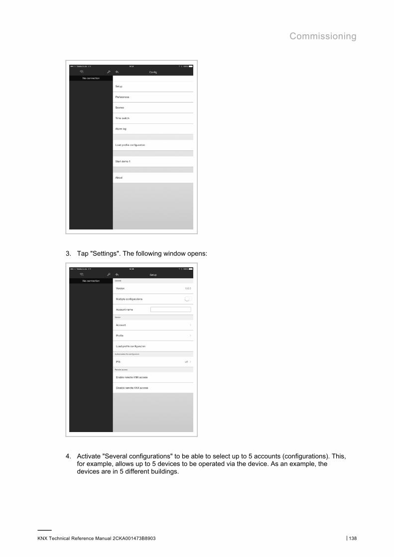
Commissioning
KNX Technical Reference Manual 2CKA001473B8903 │138
3. Tap "Settings". The following window opens:
4. Activate "Several configurations" to be able to select up to 5 accounts (configurations). This, for example, allows up to 5 devices to be operated via the device. As an example, the devices are in 5 different buildings.
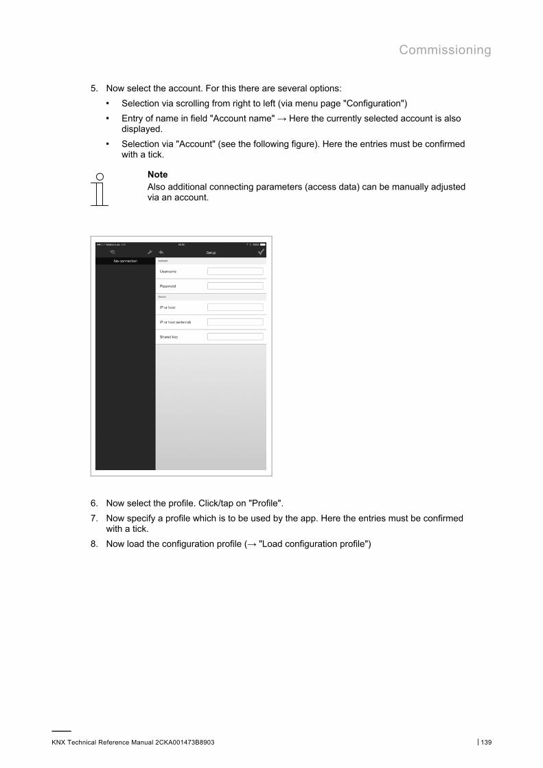
Commissioning
KNX Technical Reference Manual 2CKA001473B8903 │139
5. Now select the account. For this there are several options:
■ Selection via scrolling from right to left (via menu page "Configuration") ■ Entry of name in field "Account name" → Here the currently selected account is also
displayed. ■ Selection via "Account" (see the following figure). Here the entries must be confirmed
with a tick.
Note Also additional connecting parameters (access data) can be manually adjusted via an account.
6. Now select the profile. Click/tap on "Profile".
7. Now specify a profile which is to be used by the app. Here the entries must be confirmed with a tick.
8. Now load the configuration profile (→ "Load configuration profile")
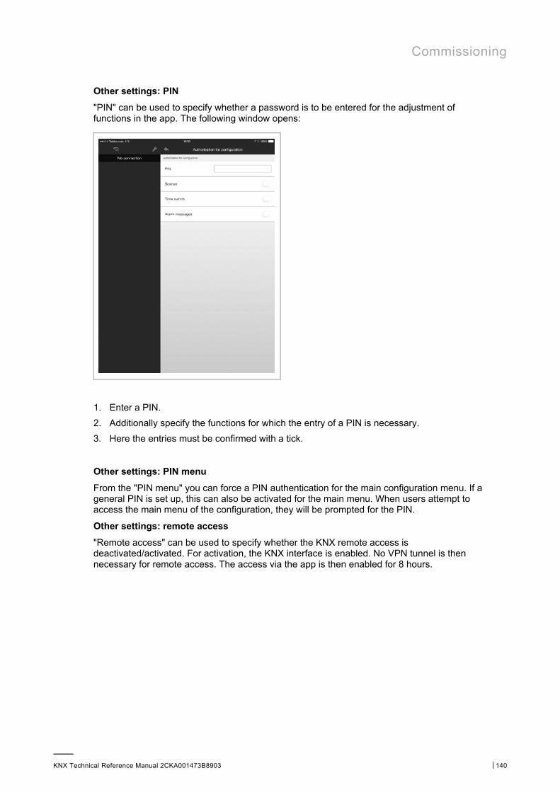
Commissioning
KNX Technical Reference Manual 2CKA001473B8903 │140
Other settings: PIN
"PIN" can be used to specify whether a password is to be entered for the adjustment of functions in the app. The following window opens:
1. Enter a PIN.
2. Additionally specify the functions for which the entry of a PIN is necessary.
3. Here the entries must be confirmed with a tick.
Other settings: PIN menu
From the "PIN menu" you can force a PIN authentication for the main configuration menu. If a general PIN is set up, this can also be activated for the main menu. When users attempt to access the main menu of the configuration, they will be prompted for the PIN.
Other settings: remote access
"Remote access" can be used to specify whether the KNX remote access is deactivated/activated. For activation, the KNX interface is enabled. No VPN tunnel is then necessary for remote access. The access via the app is then enabled for 8 hours.
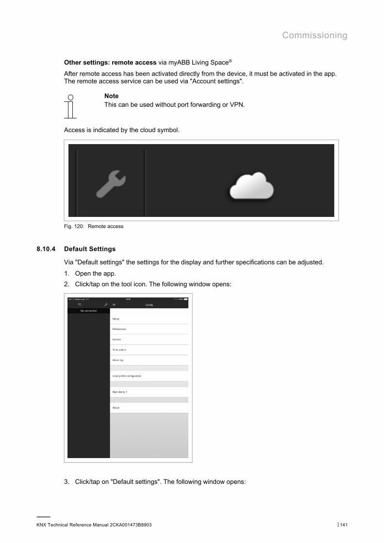
Commissioning
KNX Technical Reference Manual 2CKA001473B8903 │141
Other settings: remote access via myABB Living Space®
After remote access has been activated directly from the device, it must be activated in the app. The remote access service can be used via "Account settings".
Note This can be used without port forwarding or VPN.
Access is indicated by the cloud symbol.
Fig. 120: Remote access
8.10.4 Default Settings
Via "Default settings" the settings for the display and further specifications can be adjusted.
1. Open the app.
2. Click/tap on the tool icon. The following window opens:
3. Click/tap on "Default settings". The following window opens:
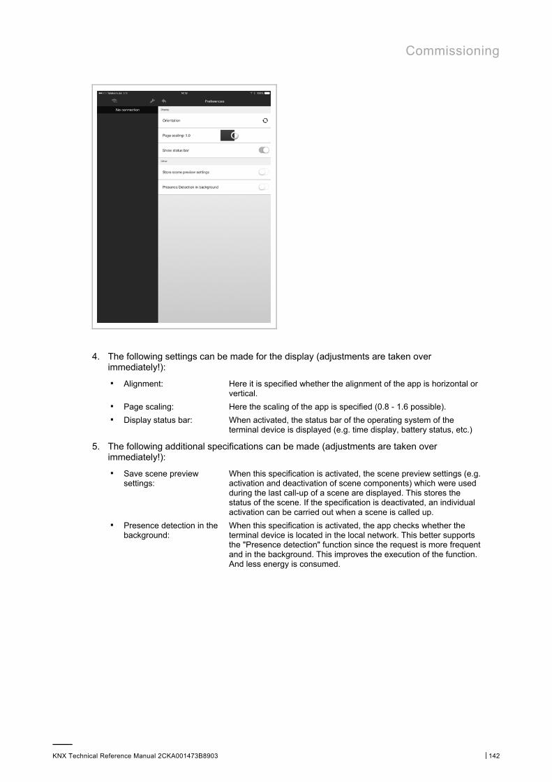
Commissioning
KNX Technical Reference Manual 2CKA001473B8903 │142
4. The following settings can be made for the display (adjustments are taken over immediately!):
■ Alignment: Here it is specified whether the alignment of the app is horizontal or vertical.
■ Page scaling: Here the scaling of the app is specified (0.8 - 1.6 possible). ■ Display status bar: When activated, the status bar of the operating system of the
terminal device is displayed (e.g. time display, battery status, etc.)
5. The following additional specifications can be made (adjustments are taken over immediately!):
■ Save scene preview settings:
When this specification is activated, the scene preview settings (e.g. activation and deactivation of scene components) which were used during the last call-up of a scene are displayed. This stores the status of the scene. If the specification is deactivated, an individual activation can be carried out when a scene is called up.
■ Presence detection in the background:
When this specification is activated, the app checks whether the terminal device is located in the local network. This better supports the "Presence detection" function since the request is more frequent and in the background. This improves the execution of the function. And less energy is consumed.
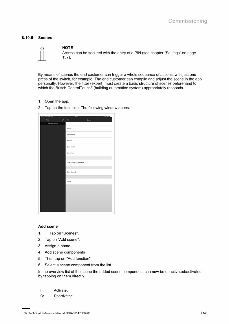
Commissioning
KNX Technical Reference Manual 2CKA001473B8903 │143
8.10.5 Scenes
NOTE Access can be secured with the entry of a PIN (see chapter “Settings“ on page 137).
By means of scenes the end customer can trigger a whole sequence of actions, with just one press of the switch, for example. The end customer can compile and adjust the scene in the app personally. However, the fitter (expert) must create a basic structure of scenes beforehand to which the Busch-ControlTouch® (building automation system) appropriately responds.
1. Open the app.
2. Tap on the tool icon. The following window opens:
Add scene
1. Tap on "Scenes".
2. Tap on "Add scene".
3. Assign a name.
4. Add scene components
5. Then tap on "Add function".
6. Select a scene component from the list.
In the overview list of the scene the added scene components can now be deactivated/activated by tapping on them directly.
I: Activated
O: Deactivated
Commissioning
KNX Technical Reference Manual 2CKA001473B8903 │144
Adjust scene
1. To change the name, tap directly on the name of the scene.
The name can now be changed.
2. To deactivate/activate scene components, select the corresponding scene.
The scene components can now be deactivated/activated by tapping on them directly.
I: Activated
O: Deactivated
1. To add scene components, select the corresponding scene.
2. Then tap on "Add function".
3. Select a scene component from the list.
In the overview list of the scene the added scene components can now be deactivated/activated by tapping on them directly.
I: Activated
O: Deactivated
Delete scene completely
Deletion is possible only if no group addresses exist!
1. Swipe over the scene entry in the list from right to left.
"Delete" appears.
2. Tap on this button.
The scene is deleted.
Additional functions
1. For a live preview you must select the corresponding scene.
2. Then tap on "Live preview".
A tick is set. Then the scene can be called up via the visualization (user interface). The scene is then replayed directly for test purposes.
1. Tap on the load function.
With this the adjusted or created scenes and their components are loaded from the app to the device.

Commissioning
KNX Technical Reference Manual 2CKA001473B8903 │145
Teach-in function
Normally, a scene can be modified from the settings menu. With the teach-in function (sending a KNX teach-in telegram) the current scene can be updated using the regular visualisation.
If you press and hold a scene element in the visualisation, the user is prompted to define whether the scene should be updated with the current values. If confirmed, all group addresses or components which are currently included in the scene are updated with the current settings.
Note uPnP/TCP commands and executed scripts are not updated by this action.
8.10.6 Timer – Time programs
NOTE Access can be secured with the entry of a PIN (see chapter “Settings“ on page 137).
Here the time programs can be created and administered.
1. Open the app.
2. Tap on the tool icon. The following window opens:
1. Tap on "Timer".
All available time programs are displayed in the window.
The colour of the text indicates whether the time program is activated or deactivated:
Red Deactivated
Green Active

Commissioning
KNX Technical Reference Manual 2CKA001473B8903 │146
Add time program
1. Click/tap on "Add timer".
The time program can be created in the window.
The setting options are as described in Chapter 8.9.4 “Optional setting of time programs (timer)“ on page 127.
Adjust time program
1. Select the corresponding time program.
The time program can be adjusted in the window.
The setting options are as described in Chapter 8.9.4 “Optional setting of time programs (timer)“ on page 127.
Delete time program
1. Swipe over the time program entry in the list from right to left.
"Delete" appears.
2. Tap on this button.
The time program is deleted.
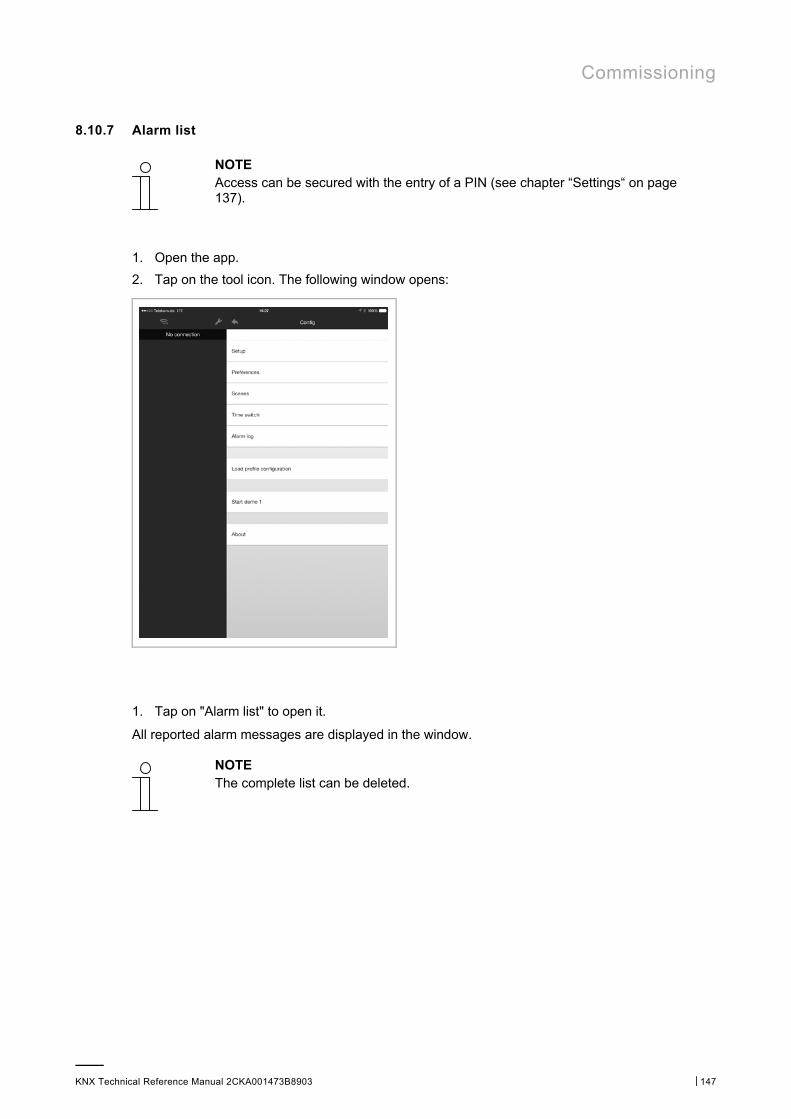
Commissioning
KNX Technical Reference Manual 2CKA001473B8903 │147
8.10.7 Alarm list
NOTE Access can be secured with the entry of a PIN (see chapter “Settings“ on page 137).
1. Open the app.
2. Tap on the tool icon. The following window opens:
1. Tap on "Alarm list" to open it.
All reported alarm messages are displayed in the window.
NOTE The complete list can be deleted.
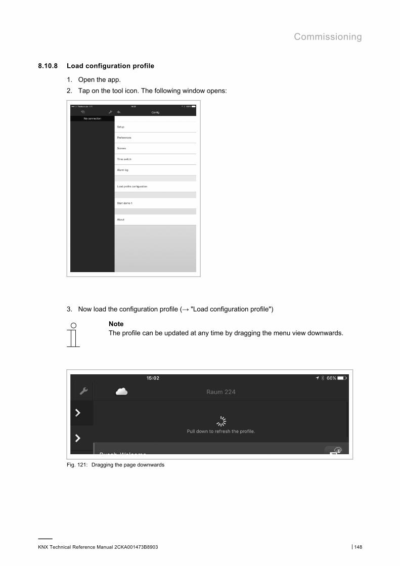
Commissioning
KNX Technical Reference Manual 2CKA001473B8903 │148
8.10.8 Load configuration profile
1. Open the app.
2. Tap on the tool icon. The following window opens:
3. Now load the configuration profile (→ "Load configuration profile")
Note The profile can be updated at any time by dragging the menu view downwards.
Fig. 121: Dragging the page downwards

Commissioning
KNX Technical Reference Manual 2CKA001473B8903 │149
8.10.9 QR code scanner
The "QR scanner" function can be opened from the configuration menu. Using this feature, users can scan a ControlTouch configuration QR code directly for the creation of an account. Once this has been scanned, you will be prompted for a password and the screen is displayed for the user account settings.
1. Open the app.
2. Tap on the tool icon.
3. Tap "QR scanner". The created QR code can be scanned in.
8.10.10 Information on data protection
1. Open the app.
2. Tap on the tool icon. The following window opens:
1. Tap on "About".
Information on data protection are displayed in the window.
Commissioning
KNX Technical Reference Manual 2CKA001473B8903 │150
8.10.11 Presence simulation
Note Access can be secured with the entry of a PIN (see chapter “Settings“ on page 137).
In the "Presence simulation" menu, the user of the presence simulation can add the components (group addresses) which are recorded for playback later on. All KNX components available for scenes and timers are displayed here.
1. Open the app.
2. Tap on the tool icon.
3. Tap "Presence simulation".
The presence simulation components are displayed in the window.
If a component is removed from the list (to remove, swipe to the left and tap), all recorded instances are removed from this component. Changes to the presence simulation must be confirmed using the "Save" button in the top right-hand corner of the screen.
The user can activate the playback function at the top of the presence simulation menu. Deactivating the playback mode returns the user to the previous mode.
There are two modes: "Record" and "Stopped".
Note You can switch between "Record" and "Stopped" by accessing the device directly.
If the user opens the app and the presence simulation is set to "Playback", a notification is displayed to the user. The user can then terminate playback directly from this notification.
The status of the simulation can be modified by a timer (see chapter “Presence simulation – self-learning function“ on page 136).
8.11 Installation and setting of the Apple Watch app
The building automation system is controlled directly via the app. It is used, for example, to manually switch lamps on or off. Only the menu pages and screens released for the Apple Watch are displayed in the app.
NOTE ■ In addition, the Busch-ControlTouch® app must be installed on a
smartphone, for example. This app establishes the connection between Busch-ControlTouch® and the Apple Watch app. The profiles are loaded in this app and transferred from here to the Apple Watch app.
■ If the connection between the Apple Watch app and the smartphone is interrupted, a few seconds will pass before this is indicated. The same applies when the connection is re-established.
■ As of Chapter 8.10 “Installation and setting of the app“ on page 137 , observe the information for installing and setting the app on a smartphone, for example.
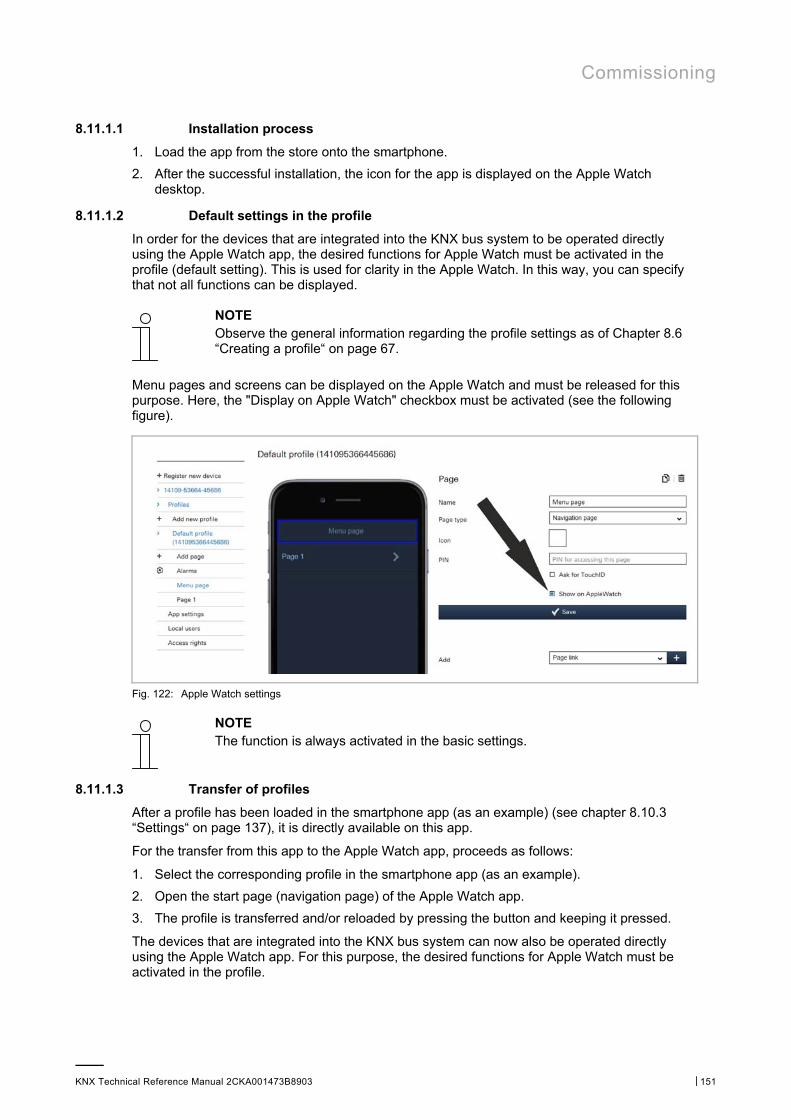
Commissioning
KNX Technical Reference Manual 2CKA001473B8903 │151
8.11.1.1 Installation process
1. Load the app from the store onto the smartphone.
2. After the successful installation, the icon for the app is displayed on the Apple Watch desktop.
8.11.1.2 Default settings in the profile
In order for the devices that are integrated into the KNX bus system to be operated directly using the Apple Watch app, the desired functions for Apple Watch must be activated in the profile (default setting). This is used for clarity in the Apple Watch. In this way, you can specify that not all functions can be displayed.
NOTE Observe the general information regarding the profile settings as of Chapter 8.6 “Creating a profile“ on page 67.
Menu pages and screens can be displayed on the Apple Watch and must be released for this purpose. Here, the "Display on Apple Watch" checkbox must be activated (see the following figure).
Fig. 122: Apple Watch settings
NOTE The function is always activated in the basic settings.
8.11.1.3 Transfer of profiles
After a profile has been loaded in the smartphone app (as an example) (see chapter 8.10.3 “Settings“ on page 137), it is directly available on this app.
For the transfer from this app to the Apple Watch app, proceeds as follows:
1. Select the corresponding profile in the smartphone app (as an example).
2. Open the start page (navigation page) of the Apple Watch app.
3. The profile is transferred and/or reloaded by pressing the button and keeping it pressed.
The devices that are integrated into the KNX bus system can now also be operated directly using the Apple Watch app. For this purpose, the desired functions for Apple Watch must be activated in the profile.
Commissioning
KNX Technical Reference Manual 2CKA001473B8903 │152
8.11.2 Apple Watch complications (QuickStarts)
For the Apple Watch, a complication can be created which can later be added to the watch face. The complication has the same symbol as the app (in black and white). The watch app is started by tapping the symbol.
Note The settings are configured in the Apple Watch (in the "Complications" menu).
8.12 Delete device
Note Please note that when adjusting a device, access must always take place via myABB Living Space®. Open the application "Busch-ControlTouch" (path: start page -> Service & Tools -> myABB Living Space® -> My installations -> Busch-ControlTouch®). In case of several devices, select the appropriate device from the list. The device can be deleted via the "Devices" tab. The rubbish bin icon must be used.
Note The profiles, however, can be retained and then allocated to other devices.
Note If a device was logged off via direct access but is still displayed in myABB Living Space®, the device can then be automatically logged off again in myABB Living Space® by clicking "OPEN" in myABB Living Space®. This re-synchronises both environments.
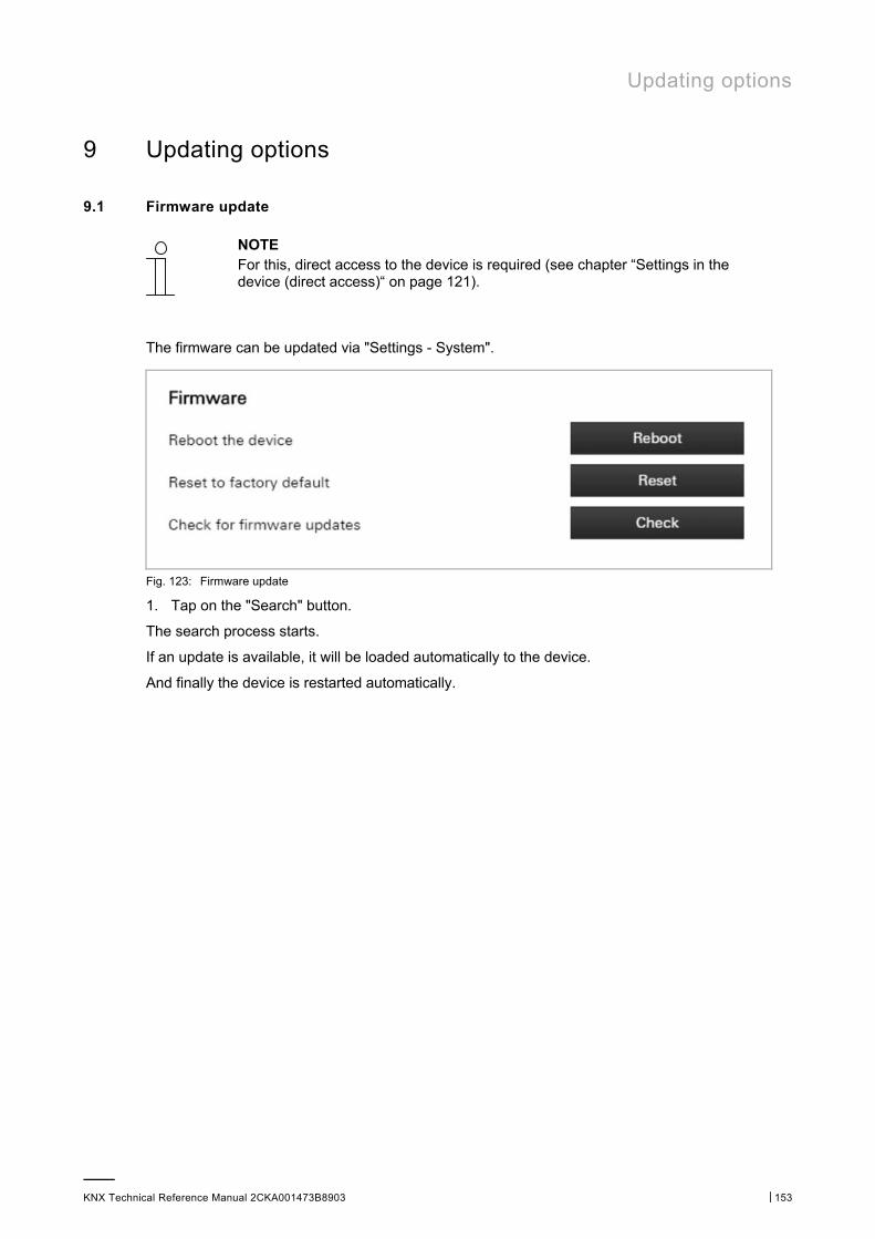
Updating options
KNX Technical Reference Manual 2CKA001473B8903 │153
9 Updating options
9.1 Firmware update
NOTE For this, direct access to the device is required (see chapter “Settings in the device (direct access)“ on page 121).
The firmware can be updated via "Settings - System".
Fig. 123: Firmware update
1. Tap on the "Search" button.
The search process starts.
If an update is available, it will be loaded automatically to the device.
And finally the device is restarted automatically.
Maintenance
KNX Technical Reference Manual 2CKA001473B8903 │154
10 Maintenance
The device is maintenance-free. In case of damage, e.g. during transport or storage), do not perform repairs. Once the device is opened, the warranty is void.
Access to the device must be guaranteed for operation, testing, inspection, maintenance and repairs (according to DIN VDE 0100-520).
10.1 Cleaning
Clean dirty devices with a soft dry cloth.
– If this is insufficient, the cloth can be moistened slightly with a soap solution.
Index
KNX Technical Reference Manual 2CKA001473B8903 │155
11 Index
A Access rights ............................................... 116 Activating remote access via myABB Living Space® . 135 Additional settings for the device (configuration page)
................................................. 23, 34, 112 Adjust alarm ............................................... 112 Adjust roles ................................................ 117 Adjust users ............................................... 116 Adjustment of KNX settings ............................. 131 Alarm list ................................................... 147 Alarms ...................................................... 109 App settings ............................................... 114 Apple Watch complications ............................. 152 Assigning a project to a device .......................... 65
B Blind ......................................................... 86 Blocking a profile (blocking function) .................. 72 Brief instructions .......................................... 22 Brief instructions for typical commissioning .......... 22
C Call-up of standard page ................................. 73 Call-up of standard profile ............................... 69 Camera ...................................................... 87 Cameras ..................................................... 44 Change Password ......................................... 132 Change temperature ...................................... 97 Cleaning .................................................... 154 Command sender .......................................... 78 Commands ......................................... 46, 78, 99 Commissioning ............................................. 22 Commissioning procedure ....................... 23, 24, 26 Configuration of Philips Hue ............................ 133 Confirming the log-in of a specialist ................... 119 Connection, installation / mounting .................... 17 Copy pages ....................................... 75, 76, 108 Copy profile ....................................... 69, 70, 71 Copy project ................................................ 65 Copying the page element .............................. 108 Create a new page ........................................ 76 Create and add alarms ................................... 111 Create and add roles ..................................... 117 Create and add users ..................................... 115 Create new profile .................................. 71, 110 Create project ............................................. 37 Creating a profile .................................... 67, 151 Creating a project ..................................... 31, 36 Creating a widget function for iOS ..................... 119 Creation of pages .......................................... 73 Creation of scripts ......................................... 54
D Data Logger ............................................. 47, 80 Date / time ................................................. 81 Default settings ........................................... 141
Delete alarm .............................................. 112 Delete device ............................................. 152 Delete profile ............................................... 71 Delete project .............................................. 65 Delete roles ............................................... 118 Deleting pages ...................................... 107, 108 Deleting user .............................................. 116 Description of functions ................................... 14 Device overview ............................................ 11 Dimensional drawings ..................................... 16 Dimmer ...................................................... 82 Display atm. pressure ..................................... 88 Display atmospheric humidity ............................ 89 Display light intensity ..................................... 79 Display of available scripts ............................. 134 Display of existing alarm messages .................... 134 Display temperature ....................................... 96 Display value .............................................. 102 Display windspeed ....................................... 107
E Electrical connection ................................. 19, 26 Empty space ................................................ 88 Environment ................................................ 10 Explanation of commissioning procedure .... 23, 24, 26 Exporting a profile (export function) ................... 72 Exporting a project ........................................ 66 Extended operation ........................................ 20
F Firmware update ......................................... 153 First login .......................................... 29, 33, 34 Function overview ......................................... 13 Functions .................................................... 13
G General information ....................................... 36 Global settings ............................................ 122 Goto account ................................................ 83 Goto menu .................................................. 84 Granting authorization .................................. 132 Group Addresses ............................................ 40 Group header ............................................... 85
I Importing a profile (import function) ................... 72 Importing a project ........................................ 66 Importing the configuration ....... 23, 24, 120, 121, 137 Improper use ................................................. 8 Information and symbols used ............................ 7 Information on data protection ........................ 149 Information on protection of the environment ........ 10 Initial commissioning of device (direct access) . 32, 35,
73, 74, 121 Installation and setting of the app .............. 137, 150 Installation and setting of the Apple Watch app .... 150 Installation process ...................................... 137

Index
KNX Technical Reference Manual 2CKA001473B8903 │156
Integration of UPnP devices ............................. 130 Intended use .................................................. 8
L Listing of profile(page) elements (actions) ... 21, 75, 77 Load configuration profile ............................... 148 Local users ........................................... 115, 116 Logging out a specialist's account ...................... 119 Login ......................................................... 35 Login / registration .......................... 23, 24, 26, 28
M Maintenance ............................................... 154 Mounting .................................................... 18
N Notes on the instruction manual .......................... 6
O Operating status ........................................... 21 Operation ................................................... 20 Operation of system via the app ............. 21, 27, 137 Optional creation of scenes ............................. 125 Optional setting of time programs (timer) ..... 127, 146 Overview of alarms ....................................... 111 Overview of configuration ................................ 27 Overview of roles ......................................... 116 Overview of types ......................................... 12 Overview of users ......................................... 115
P Page link .................................................... 92 Preparatory steps .......................................... 26 Presence detection ........................................ 49 Presence simulation ................................ 136, 150 Profile backup .............................................. 71 Project backup ............................................. 65 Proxy settings – Internet connection (Port allocation)
........................................................... 129 Push button row ........................................... 94
Q QR code scanner .......................................... 149 Qualification of personnel .................................. 8
R Reboot the device ........................................ 134 Requirements for the electrician ....................... 17 RESET ........................................................ 20
Reset of the application .................................. 20 Reset options ............................................... 20 Reset to factory default ................................. 135 Restoring a backup profile ................................ 72 Restoring a backup project ............................... 66 RGB control ................................................. 90 Roles ....................................................... 116 RTC mode selection ........................................ 77
S Safety ......................................................... 7 Safety instructions .......................................... 9 Scene ......................................................... 93 Scenes ...................................................... 143 Scope of supply ............................................. 12 Scripts ........................................................ 52 Self-learning function ............................. 136, 150 Sending an invitation to the customer ....... 34, 35, 118 Settings ................. 21, 137, 143, 145, 147, 150, 151 Settings in the device (direct access) ..... 114, 121, 153 Setup and function ......................................... 11 Start screen after installation .......................... 137 Static text ................................................... 92 Status specifications ..................................... 124 Switch ........................................................ 91 System configuration ................................. 31, 36
T Target group ................................................. 8 Technical data .............................................. 15 Timer – Time programs .................................. 145 Triggers ................................................ 50, 112 Typical commissioning ..................................... 22
U Updating options ......................................... 153 UPnP slider .................................................. 99 User protocols ............................................ 132
V Value controller .......................................... 103 Value push button ........................................ 106 Value transmitter ........................................ 105 Variable text .............................................. 100
W Web page .................................................. 101
A member of the ABB Group Busch-Jaeger Elektro GmbH PO box 58505 Lüdenscheid Freisenbergstraße 2 58513 Lüdenscheid www.BUSCH-JAEGER.com [email protected] Central sales service: Tel.: +49 2351 956-1600 Fax: +49 2351 956-1700
Notice We reserve the right to make technical changes at all times as well as changes to the contents of this document without prior notice. The detailed specifications agreed upon apply for orders. ABB accepts no responsibility for possible errors or incompleteness in this document. We reserve all rights to this document and the topics and illustrations contained therein. The document and its contents, or extracts thereof, must not be reproduced, transmitted or reused by third parties without prior written consent by ABB
KN
X T
ech
nic
al R
efe
ren
ce M
an
ua
l 2
CK
A0
01
47
3B
89
03
Philips and Hue are brands of Philips Electronics N.V. Apple Store, iPhone, iPad, iPod touch and Apple Watch are registered trademarks of Apple Inc. in the USA and other countries. Google Store and Android are brands of Google Inc.
Copyright© 2017 Busch-Jaeger Elektro GmbH All rights reserved


![DAILY BOARD FOR: 21.07.2017(FRIDAY) Login: …...2017/07/21 · 1‐ ] DAILY BOARD FOR: 21.07.2017(FRIDAY) Login: . Court Room JUDGES NAME OM/ADM/HP /TM/JUD Sr. No. Case No. Name](https://img.pdfslide.us/doc/110x75/5eae8441dca44b60bb1eb7b7/daily-board-for-21072017friday-login-20170721-1a-daily-board.jpg)