Embed Size (px)
Citation preview
7/22/2019 2Ati
http://slidepdf.com/reader/full/2ati 1/8
Standard Edition Section Inquiry # Question Reply
2A-WSD 21st Edition,
Dec. 2000
General 2A-02-09 Background: API has two standards for fixed offshore platforms: API
2A-LRFD and API 2A WSD and we are not sure which standard use. RP
2A WSD states in the Foreword that the AISC Load & Resistance Factor
Design (LRFD), First Edition is not recommended for design.
Question 1: Can we use the latest edition of AISC-LRFD (AISC-360-05)
for the design of offshore structures?
Question 2: We have to perform an assessment on a platform structure
designed 20 years ago according to API 2A-WSD. Can we use API 2A-
LRFD (of course using the loading, factors, etc from the same
standard), or it is required to use API 2A WSD?
Reply 1: No. Please refer to ISO 19902, Petroleum and natural gas
industries — Fixed steel offshore structures. ISO 19902 was based on API
2A-LRFD and has been updated to reflect the latest information.
Reply 2: It is not recommended to mix the principles of WSD with LRFD. If
the structure was designed using WSD, it should be assessed using WSD.
Similarly, if the structure was designed to LRFD, it should be assessed using
LRFD. API is developing RP 2SIM, Structural Integrity Management, to
address the assessment of existing structures, which is planned for
publication in 2010.
2A-WSD 21st Edition,
Dec. 2000
General 2A-02-11 It seems that there is no specific recommendation in API 2A-WSD for a
factor of safety (FOS) for jacket overturning prior to pile installation.
What is the recommended minimum FOS for overturning?
See API 2A-WSD, Section 12.4.5.
2A-WSD 21st Edition,
Dec. 2000
2.3.1b 2A-09-11 Background: In Section 2.3.1.b, Item 11, it is stated that the wave crest
should be positioned relative to the structure . . . It should be kept in
mind that (a) maximum base shear . . .; (b) in special cases of waves
with low steepness and an opposing current, maximum global
structure force may occur near the wave trough rather than near the
wave crest.
Question: Would you please clarify whether Case (b) is specific to
some regions where wave and current directions could be opposite, or
in all regions we have to apply both cases where (1) current and wave
directions are opposite and (2) current and wave directions are same?
The requirement is to position the wave crest relative to the structure so that
total base shear and overturning moment have their maximum values. There
is no general statement concerning the worldwide geographic locations that
are likely to experience waves and currents in opposite directions. For
design, site-specific environmental data should be obtained from a metocean
consultant. Depending on the nature of the data, analyzing both cases may or
may not be necessary. In any case, t he sentence in (b) is simply a warning
that in the case of low steeepness and opposing current the wave positions
that originate the largest loads on the structure may be close to the trough
rather than to the crest.
2A-WSD 21st Edition,
Dec. 2000
2.3.2e 2A-03-08 Background: Section 2.3.2.e gives shape coefficient values for
perpendicular wind approach angles on each projected area. This
section further states that for “overall projected area of the platform”the Cs value is 1.0. Most offshore platform facilities are rectangular or
square shaped in plan, that is, they have two flat projected faces at 90
degrees to each other. For wind approach perpendicular to these, the
interpretation is straightforward.
Question: Are wind approach angles that are not perpendicular to
these faces considered in this section?
Non-perpendicular wind forces are addressed as follows.
a) Compute the projected area perpendicular to the wind, apply the full windpressure to that projected area, and distribute the forces to joints exposed to
that wind. The forces are resolved into components parallel to global axes for
application to joints.
b) For a unit wind force, compute the component (direction cosine) of the
wind perpendicular to each of the two flat projected faces of the platform.
Multiply the area of the flat projected face times the component (direction
cosine) perpendicular to it and apply the full wind pressure to that reduced
area in the component direction.
API RP 2A - Recommended Practice for Planning, Designing, and Constructing Fixed Offshore Platforms—Working Stress
DesignLast update: January 4, 2014
Page 1 of 8
7/22/2019 2Ati
http://slidepdf.com/reader/full/2ati 2/8
Standard Edition Section Inquiry # Question Reply
API RP 2A - Recommended Practice for Planning, Designing, and Constructing Fixed Offshore Platforms—Working Stress
DesignLast update: January 4, 2014
2A-WSD 21st Edition,
Dec. 2000
2.3.6 2A-03-08 Background: API RP2A-WSD, Section 2.3.6.b.2, states that for areas
with low seismic activity between 0.05g and 0.10g, al l requirements are
satisfied if the rare, intense earthquake is used for strength
requirements and tubular braces are designed for computed joint loads
due to rare intense earthquake. In section 2.3.6.e.1, the stresses in thetubular chords are computed based on twice the strength level seismic
loads in combination with gravity, hydrostatic and buoyancy loads.
Question: in low seismic areas, are the chord stresses computed
based on twice the rare intense earthquake or twice the strength level
seismic loads?
The chord stresses should be computed based on the rare intense
earthquake (DLE), not twice the DLE. Twice the strength level (SLE) is an
approximate method of obtaining the chord stresses for the rare intense
earthquake (DLE), and can be used instead (assuming California conditions).
If the platform is not in California, the DLE chord stresses should be used.
Studies have shown that for offshore California, DLE loads are about twice
the SLE loads, hence the factor of two; this is not true in all seismic regions.
2A-WSD 21st Edition,
Dec. 2000
2.3.6c 2A-06-08 In Section 2.3.6c of API RP 2A-WSD, it states “For the strength
requirement, the basic AISC allowable stresses and those presented in
Section 3.2 may be increased by 70 percent”. If the allowable is 0.66Fy,
is it okay to have the allowable stress equal to 1.12Fy (1.7 × 0.66 Fy =
1.12 Fy)?
Yes. See C2.3.6c Part 4, Paragraph 4 for further explanation. The 70 percent
allowable stress increase allows minor yielding but no significant damage to
the member for SLE loading. The intent is to provide a simplified estimate of
member performance at SLE loading while still using a linear method such as
response spectra analysis. This does not mean that the member design is
plastic – the intent of SLE design is that all members and joints should still be
elastic, although they can be above normal allowable and very close to
plastic. If the member is deemed as being plastic at SLE loading then it
should be redesigned to be elastic (but with little or no allowable). Note that
the platform must also pass the DLE requirement that ensures it does not
collapse on a global basis.
Page 2 of 8
7/22/2019 2Ati
http://slidepdf.com/reader/full/2ati 3/8
Standard Edition Section Inquiry # Question Reply
API RP 2A - Recommended Practice for Planning, Designing, and Constructing Fixed Offshore Platforms—Working Stress
DesignLast update: January 4, 2014
2A-WSD 21st Edition,
Dec. 2000
2.3.6a 2A-03-12 Background: Section 2.3.6a2 of API RP 2A-WSD states the following.
“For areas where the strength level design horizontal ground
acceleration is in the range of 0.05g to 0.10g, inclusive, all of the
earthquake requirements, except those for deck appurtenances, may
be considered satisfied if the strength requirements (Section 2.3.6c) aremet using the ground motion intensity and characteristic of the rare
intense earthquake in lieu of the strength level earthquake . . .”
In this event, the deck appurtenances should be designed for the
strength level earthquake in accordance with 2.3.6e2, but the ductility
requirement (Section 2.3.6d) are waived, and tubular joints need be
designed for allowable stresses specified in Section 2.3.6e1 using the
computed joint loads instead of the tensile load or compressive
buckling load of the member.
Note: as per Section 2.3.6.e, the deck appurtenances that typically do
not meet the “rigid body” criterion are drilling rigs, flare booms, deck
cantilevers, . . .” Furthermore on the last paragraph, it says “Deck-
supported structures, and equipment tie-downs, should be designed
with a one-third increase in basic allowable stresses, unless theframing pattern, consequences of failure, metallurgy, and/or site-
specific ground motion intensities suggest otherwise”. The statement
of “70% increase in basic allowable stress” in the table in Section 7.1
of JM1 Structural Design Basis is applicable for JM1 jacket and deck.
Question: Is it correct that only the jacket and deck should be checked
with a 70% increase in basic allowable stress, but for flare boom
structure, it should be checked with a one-third increase in basic
allowable stress?
Yes. The 1.33 increase in allowable stresses applies to strength level
earthquake check for deck drilling and well servicing structures, while the 1.7
increase applies ductility level earthquake for jacket and deck framing. API
4F specifies no DLE check for deck drilling and well servicing structures.
2A-WSD 21st Edition,
Dec. 2000
2.3.6c 2A-04-10 Background: Section 2.3.6.c 3) states earthquake loading should be
combined with other simultaneous loadings such as gravity, buoyancy,
and hydrostatic pressure. Gravity loading should include the platformdead weight (comprised of the weight of the structure, equipment,
appurtenances), actual live loads and 75% of the maximum supply and
storage loads. Item 4) in that same section states for the strength
requirement, the basic AISC allowable stresses and those presented in
Section 3.2 may be increased by 70%
Question: Can you show equations similar to ASCE 7-05 that show the
load factor for each load and where you apply the 70% increase? Does
the increase apply to all loads or earthquake load only? ASCE 7-05
reduces the earthquake load and uses 0.7E (similar to increase
allowable load).
API 2A-WSD is based on working stress design that modifies the stress of
the steel material to an “allowable” level that is then compared to the stresses
caused by the unfactored design loads. For earthquake strengthrequirements the basic AISC allowable stresses presented in Sections 3 and
4 for steel and joint design may be increased by 70% as indicated. Factors
should not be applied to any of the applicable loads during an earthquake –
gravity, buoyancy, hydrostatic and earthquake (alternatively consider the load
factor to be 1.0 in LRFD terms). Note that API does recommend a 75% factor
for the maximum supply and storage loads. ASCE 7-05 is a LRFD approach
that applies factors to both load and resistance and these LRFD factors
should not be compared to the API WSD approach.
Page 3 of 8
7/22/2019 2Ati
http://slidepdf.com/reader/full/2ati 4/8
Standard Edition Section Inquiry # Question Reply
API RP 2A - Recommended Practice for Planning, Designing, and Constructing Fixed Offshore Platforms—Working Stress
DesignLast update: January 4, 2014
2A-WSD 21st Edition,
Dec. 2000
2.3.6d 2A-04-11 Clause 2.3.6d states “that for a conventional jacket-type structure with
eight or more legs, no ductility analysis is required if the structure is to
be located in an area where the intensity of rare intense earthquake
ground motion to strength level earthquake ground motion is two or
less”.
Please see the attached figure which shows the platform has four main
jacket legs. There are two skirt piles/legs attached to each leg. This
platform does not have any piles through the main four legs. Should
this platform be considered as an eight-legged platform or a four-
The jacket has four main legs. The two piles at each corner will work much
like a single pile, with some slight differences in load sharing. From the point
of view of the jacket framing scheme and of the load distribution in the jacket,
this is a four legged jacket and not an eight-leg jacket, and according to
2.3.6d a ductility analysis is required.
2A-WSD 21st Edition,
Dec. 2000
3.1.1 2A-01-09 Background: Section 3.1.1 of API 2A-WSD states, “unless otherwise
recommended, the platform should be designed so that all members
are proportioned for basic allowable stresses specified by the AISC
Specification for the Design, Fabrication and Erection of Structural
Steel for Buildings, latest edition”. It goes on to say that “the AISC
Load and Resistance Factor Design, First Edition code is not
recommended for design of offshore platforms.” The latest edition of
AISC 360 (March 9, 2005) covers both ASD and LRFD.
Question: Is the ASD component of AISC 360-05 recommended for the
design of offshore structures in accordance with API 2A WSD?
No. The appropriate reference continues to be the AISC Manual of Steel
Construction, Allowable Stress Design, 9th Edition, June 1,1989. The API 2A
Task Group is addressing this issue for a future edition of the standard.
2A-WSD 21st Edition,
Dec. 2000
3.1.1 2A-01-10 Background: Section 3.1.1 states, "Unless otherwise recommended
the platform should be designed so that all members are proportioned
for basic allowable stresses specified by the AISC specification for the
design, fabrication, and erection of structural steel for buildings latest
edition."
In reference to C2.2 of the 2005 AISC specification "where the ration of
second order drift to the first order drift is greater than 1.5, the required
strengths shall be determined by the direct analysis method of
Appendix 7", knowing that the direct analysis method is based on
second order analysis. Please clarify if the equations of Sections 3 and
4 of RP 2A-WSD are consistent with straining actions out coming fromsecond order analysis?
API RP 2A-WSD, 21st Edition, should be used in combination with the
Specification for Structural Steel Buildings – Allowable Stress Design and
Plastic Design, found in the 9th Edition of the AISC Manual of Steel
Construction.
2A-WSD 21st Edition,
Dec. 2000
4.2.3 2A-05-11 It is our understanding that the 50% tubular joint can strength check in
Section 4 is only required for in-place conditions. Therefore, only the
joint can load check is required for temporary conditions such as
loadout, transport, lift, and launch. Furthermore, we understand that
the joint must be sized for 50% of the capacity of the brace members
size that is needed to meet the in-place conditions. For example, if a
brace member needs to be 24 in. dia. x 0.5 in. to satisfy the in-place
condition, but it must be increased to 24 in. dia. x 0.75 in. for a
temporary condition, then the 50% strength check only needs to be
completed for the 24 in. dia. x 0.5 in. member. Please confirm our
understanding of the above statements.
The minimum capacity requirement applies to all load conditions, not just in-
place. However, the calculation of effective strength of secondary braces may
omit consideration of any strengthening due to localized loadings (such as
those induced by loadout, lifting or launch conditions), corrosion allowance,
section availability, etc. The decision to classify a member as “secondary”
should be based on sound engineering insight, reflecting, among other
considerations, the possible consequences of the failure of the member in
question.
Page 4 of 8
7/22/2019 2Ati
http://slidepdf.com/reader/full/2ati 5/8
Standard Edition Section Inquiry # Question Reply
API RP 2A - Recommended Practice for Planning, Designing, and Constructing Fixed Offshore Platforms—Working Stress
DesignLast update: January 4, 2014
2A-WSD 21st Edition,
Dec. 2000
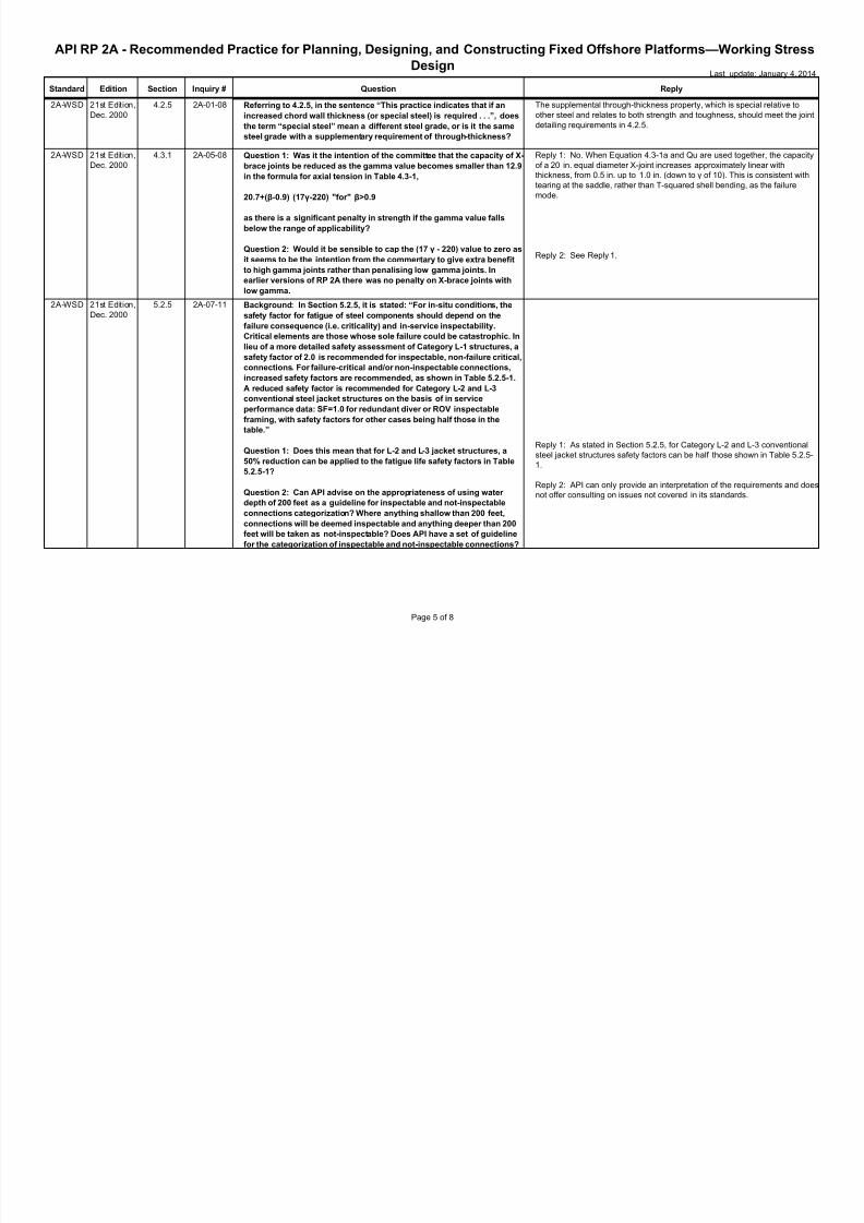
4.2.5 2A-01-08 Referring to 4.2.5, in the sentence “This practice indicates that if an
increased chord wall thickness (or special steel) is required . . .”, does
the term “special steel” mean a different steel grade, or is it the same
steel grade with a supplementary requirement of through-thickness?
The supplemental through-thickness property, which is special relative to
other steel and relates to both strength and toughness, should meet the joint
detailing requirements in 4.2.5.
2A-WSD 21st Edition,
Dec. 2000
4.3.1 2A-05-08 Question 1: Was it the intention of the committee that the capacity of X-
brace joints be reduced as the gamma value becomes smaller than 12.9
in the formula for axial tension in Table 4.3-1,
20.7+(β-0.9) (17γ-220) "for" β>0.9
as there is a significant penalty in strength if the gamma value falls
below the range of applicability?
Question 2: Would it be sensible to cap the (17 γ - 220) value to zero as
it seems to be the intention from the commentary to give extra benefit
to high gamma joints rather than penalising low gamma joints. In
earlier versions of RP 2A there was no penalty on X-brace joints with
low gamma.
Reply 1: No. When Equation 4.3-1a and Qu are used together, the capacity
of a 20 in. equal diameter X-joint increases approximately linear with
thickness, from 0.5 in. up to 1.0 in. (down to γ of 10). This is consistent with
tearing at the saddle, rather than T-squared shell bending, as the failure
mode.
Reply 2: See Reply 1.
2A-WSD 21st Edition,
Dec. 2000
5.2.5 2A-07-11 Background: In Section 5.2.5, it is stated: “For in-situ conditions, the
safety factor for fatigue of steel components should depend on the
failure consequence (i.e. criticality) and in-service inspectability.
Critical elements are those whose sole failure could be catastrophic. In
lieu of a more detailed safety assessment of Category L-1 structures, a
safety factor of 2.0 is recommended for inspectable, non-failure critical,
connections. For failure-critical and/or non-inspectable connections,
increased safety factors are recommended, as shown in Table 5.2.5-1.
A reduced safety factor is recommended for Category L-2 and L-3
conventional steel jacket structures on the basis of in service
performance data: SF=1.0 for redundant diver or ROV inspectable
framing, with safety factors for other cases being half those in the
table.”
Question 1: Does this mean that for L-2 and L-3 jacket structures, a50% reduction can be applied to the fatigue life safety factors in Table
5.2.5-1?
Question 2: Can API advise on the appropriateness of using water
depth of 200 feet as a guideline for inspectable and not-inspectable
connections categorization? Where anything shallow than 200 feet,
connections will be deemed inspectable and anything deeper than 200
feet will be taken as not-inspectable? Does API have a set of guideline
for the categorization of inspectable and not-inspectable connections?
Reply 1: As stated in Section 5.2.5, for Category L-2 and L-3 conventional
steel jacket structures safety factors can be half those shown in Table 5.2.5-1.
Reply 2: API can only provide an interpretation of the requirements and does
not offer consulting on issues not covered in its standards.
Page 5 of 8
7/22/2019 2Ati
http://slidepdf.com/reader/full/2ati 6/8
Standard Edition Section Inquiry # Question Reply
API RP 2A - Recommended Practice for Planning, Designing, and Constructing Fixed Offshore Platforms—Working Stress
DesignLast update: January 4, 2014
2A-WSD 21st Edition,
Dec. 2000
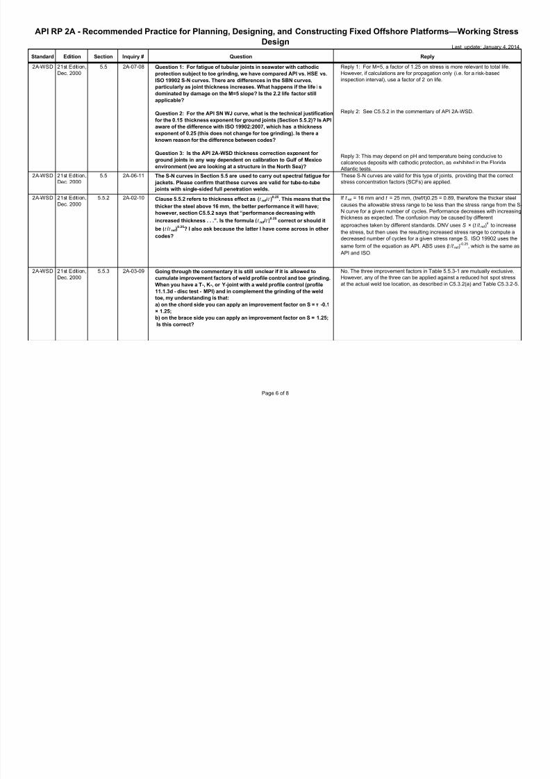
5.5 2A-07-08 Question 1: For fatigue of tubular joints in seawater with cathodic
protection subject to toe grinding, we have compared API vs. HSE vs.
ISO 19902 S-N curves. There are differences in the SBN curves,
particularly as joint thickness increases. What happens if the life i s
dominated by damage on the M=5 slope? Is the 2.2 life factor stillapplicable?
Question 2: For the API SN WJ curve, what is the technical justification
for the 0.15 thickness exponent for ground joints (Section 5.5.2)? Is API
aware of the difference with ISO 19902:2007, which has a thickness
exponent of 0.25 (this does not change for toe grinding). Is there a
known reason for the difference between codes?
Question 3: Is the API 2A-WSD thickness correction exponent for
ground joints in any way dependent on calibration to Gulf of Mexico
environment (we are looking at a structure in the North Sea)?
Reply 1: For M=5, a factor of 1.25 on stress is more relevant to total life.
However, if calculations are for propagation only (i.e. for a risk-based
inspection interval), use a factor of 2 on life.
Reply 2: See C5.5.2 in the commentary of API 2A-WSD.
Reply 3: This may depend on pH and temperature being conducive to
calcareous deposits with cathodic protection, as exhibited in the Florida
Atlantic tests.
2A-WSD 21st Edition,
Dec. 2000
5.5 2A-06-11 The S-N curves in Section 5.5 are used to carry out spectral fatigue for
jackets. Please confirm that these curves are valid for tube-to-tube
joints with single-sided full penetration welds.
These S-N curves are valid for this type of joints, providing that the correct
stress concentration factors (SCFs) are applied.
2A-WSD 21st Edition,
Dec. 2000
5.5.2 2A-02-10 Clause 5.5.2 refers to thickness effect as (t ref /t )0.25
. This means that the
thicker the steel above 16 mm, the better performance it will have;
however, section C5.5.2 says that “performance decreasing with
increased thickness . . .”. Is the formula (t ref /t )0.25
correct or should it
be (t /t ref )0.25
? I also ask because the latter I have come across in other
codes?
If t ref = 16 mm and t = 25 mm, (tref/t)0.25 = 0.89, therefore the thicker steel
causes the allowable stress range to be less than the stress range from the S-
N curve for a given number of cycles. Performance decreases with increasing
thickness as expected. The confusion may be caused by different
approaches taken by different standards. DNV uses S × (t /t ref )k to increase
the stress, but then uses the resulting increased stress range to compute a
decreased number of cycles for a given stress range S. ISO 19902 uses the
same form of the equation as API. ABS uses (t /t ref )-0.25
, which is the same as
API and ISO.
2A-WSD 21st Edition,
Dec. 2000
5.5.3 2A-03-09 Going through the commentary it is still unclear if it is allowed to
cumulate improvement factors of weld profile control and toe grinding.
When you have a T-, K-, or Y-joint with a weld profile control (profile
11.1.3d - disc test - MPI) and in complement the grinding of the weld
toe, my understanding is that:
a) on the chord side you can apply an improvement factor on S = τ -0.1
× 1.25;
b) on the brace side you can apply an improvement factor on S = 1.25;
Is this correct?
No. The three improvement factors in Table 5.5.3-1 are mutually exclusive.
However, any of the three can be applied against a reduced hot spot stress
at the actual weld toe location, as described in C5.3.2(a) and Table C5.3.2-5.
Page 6 of 8
7/22/2019 2Ati
http://slidepdf.com/reader/full/2ati 7/8
Standard Edition Section Inquiry # Question Reply
API RP 2A - Recommended Practice for Planning, Designing, and Constructing Fixed Offshore Platforms—Working Stress
DesignLast update: January 4, 2014
2A-WSD 21st Edition,
Dec. 2000
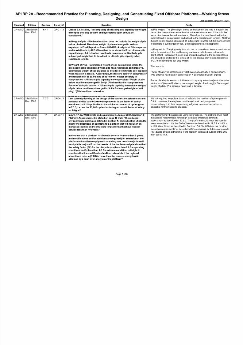
6.4.1 2A-01-13 Clause 6.4.1 states, "In computing pile loading and capacity the weight
of the pile-soil plug system and hydrostatic uplift should be
considered."
a) Weight of pile - Pile head reaction does not include the weight of pilebelow pile head. Therefore, weight of pile submerged in soil (as
explained in Final Report on Project 83-42B - Analysis of Pile response
under axial loads by R.E. Olson) has to be deducted from ultimate pile
capacity (eqn. 6.4.1-1) when reaction is compressive. Similarly, pile
submerged weight has to be added to ultimate pile capacity when
reaction is tensile.
b) Weight of Plug - Submerged weight of soil column/plug inside the
pile need not be considered when pile head reaction is compressive.
Submerged weight of soil plug has to be added to ultimate pile capacity
when reaction is tensile. Accordingly, the factors safety in compression
and tension can be calculated at as follows: Factor of safety in
compression = (Ultimate pile capacity in compression - Weight of pile
below mudline submerged in Soil) / (Pile head load in compression)
Factor of safety in tension = (Ultimate pile capacity in tension + Weightof pile below mudline submerged in Soil + Submerged weight of soil
plug) / (Pile head load in tension)
a) Pile weight: The pile weight should be included in the load if it acts in the
same direction as the external load or in the resistance term if it acts in the
same direction as the soil resistance. Therefore it should be added to the
external load in compression and added to the resistance in tension. Not that
the pile weight can be calculated as submerged in water but it is more correct
to calculate it submerged in soil. Both approaches are acceptable.
b) Plug weight: The plug weight should not be considered in compression due
to the formulation of the end bearing resistance, which does not include
depth effect. In tension the soil plug should be added to the soil resistance
and should be limited to the lowest of 1), the internal skin friction resistance
or 2), the submerged soil plug weight.
That leads to:
Factor of safety in compression = (Ultimate soil capacity in compression) /
(Pile external head load in compression + Submerged weight of pile)
Factor of safety in tension = (Ultimate soil capacity in tension [which includes
minimum of (internal friction or submerged weight of soil plug)] + Submerged
weight of pile) / (Pile external head load in tension)
2A-WSD 21st Edition,
Dec. 2000
7.3.3 2A-04-13 I am currently looking at the design of the connection between a crane
pedestal and its connection to the platform. Is the factor of safety
mentioned in 5.2.5 applicable to the minimum number of cycles given
in 7.3.3, i.e. are the 25,000 cycles including an in-built factor of safety
on fatigue?
It is not required to apply a factor of safety to the number of cycles given in
7.3.3. However, the engineer has the option of designing more
conservatively if, in their engineering judgment, more conservatism is
advisable for their specific situation.
2A-WSD 21st Edition,
Dec. 2000
17 2A-03-11 In API-RP-2A-WSD Errata and supplement 3, August 2007, Section 1.9
Platform Assessment, it is stated on page 10 that: “The reduced
environmental criteria as defined in Section 17 should not be utilized to
justify modifications or additions to a platform that will result in an
increased loading on the structure for platforms that have been inservice less than five years.”
In the case that a platform has been in service for more than 5 years
and modifications and/or additions are required (i.e. extension of the
platform to install new equipment or adding new conductor(s for well
head platforms) and from the results of the in-place analysis show that
the safety factor (SF) for the pile(s) is (are) less than 2.0 for operating
conditions and/or less than 1.5 for extreme condition, is it right to
conclude that the modification/addition is feasible if the regional
acceptance criteria (RAC) is more than the reserve strength ratio
obtained by a push over analysis of the platform?
The platform may be assessed using lower criteria. The platform must meet
the specific requirements for design level and or ultimate strength
assessment as described in 17.5.2. The platform should meet the specific
metocean criteria if it is the Gulf of Mexico as described in 17.6.2.a or if it is
in U.S. West Coast as described in Section 17.6.2.b. API does not provide
metocean requirements for any other offshore regions. API does not provide
RSR based criteria at this time. If the platform is located outside of the U.S.
then see C.17.1.
Page 7 of 8
7/22/2019 2Ati
http://slidepdf.com/reader/full/2ati 8/8
Standard Edition Section Inquiry # Question Reply
API RP 2A - Recommended Practice for Planning, Designing, and Constructing Fixed Offshore Platforms—Working Stress
DesignLast update: January 4, 2014
2A-WSD 21st Edition,
Dec. 2000
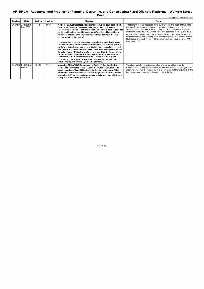
17.5 2A-03-11 In API-RP-2A-WSD Errata and supplement 3, August 2007, section 1.9
Platform Assessment, it is stated on page 10 that: “The reduced
environmental criteria as defined in Section 17 should not be utilized to
justify modifications or additions to a platform that will result in an
increased loading on the structure for platforms that have been in
service less than five years.”
In the case that a platform has been in service for more than 5 years
and modifications and/or additions are required (i.e. extension of the
platform to install new equipment or adding new conductor(s for well
head platforms) and from the results of the in-place analysis show that
the safety factor (SF) for the pile(s) is (are) less than 2.0 for operating
conditions and/or less than 1.5 for extreme condition, is it right to
conclude that the modification/addition is feasible if the regional
acceptance criteria (RAC) is more than the reserve strength ratio
obtained by a push over analysis of the platform?
The platform may be assessed using lower criteria. The platform must meet
the specific requirements for design level and or ultimate strength
assessment as described in 17.5.2. The platform should meet the specific
metocean criteria if it is the Gulf of Mexico as described in 17.6.2.a or if it is
in U.S. West Coast as described in Section 17.6.2.b. API does not provide
metocean requirements for any other offshore regions. API does not provide
RSR based criteria at this time. If the platform is located outside of the U.S.
then see C.17.1.
2A-WSD 21st Edition,
Dec. 2000
C.4.2.3 2A-01-11 According API 2A-WSD, Supplement 3, Oct 2007, Section C.4.2.3,
“…the utilization factor of critical joints be limited to 85% that of its
branch members.” I would like to clarify the above statement. What I
understand from this statement is 50% strength check criteria will not
be applicable if nominal load check unity ratio is l ess than 0.85. Please
clarify the understanding is correct.
The statement should be interpreted as follows: for critical joints the
requirement that the joint capacity be no less than 50% of the strength of the
incoming brace may be replaced with a requirement that the unit check of the
joint be no more than 85% of the unit check of the brace.
Page 8 of 8


