Embed Size (px)
Citation preview
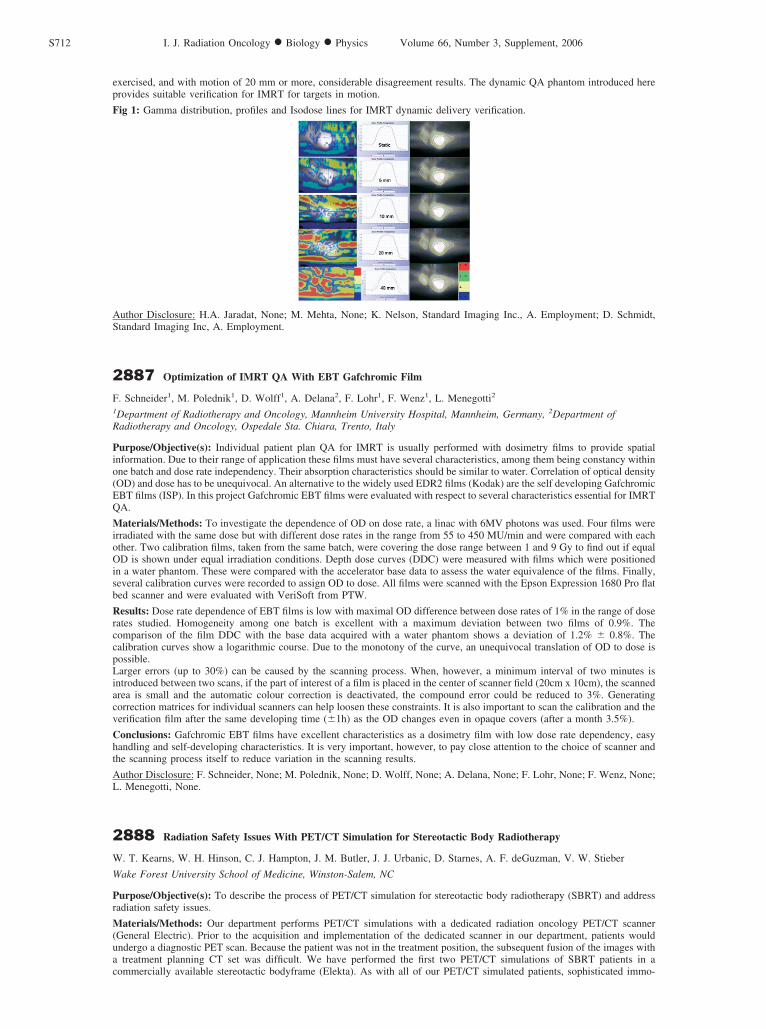
exercised, and with motion of 20 mm or more, considerable disagreement results. The dynamic QA phantom introduced hereprovides suitable verification for IMRT for targets in motion.
Fig 1: Gamma distribution, profiles and Isodose lines for IMRT dynamic delivery verification.
Author Disclosure: H.A. Jaradat, None; M. Mehta, None; K. Nelson, Standard Imaging Inc., A. Employment; D. Schmidt,Standard Imaging Inc, A. Employment.
2887 Optimization of IMRT QA With EBT Gafchromic Film
F. Schneider1, M. Polednik1, D. Wolff1, A. Delana2, F. Lohr1, F. Wenz1, L. Menegotti2
1Department of Radiotherapy and Oncology, Mannheim University Hospital, Mannheim, Germany, 2Department ofRadiotherapy and Oncology, Ospedale Sta. Chiara, Trento, Italy
Purpose/Objective(s): Individual patient plan QA for IMRT is usually performed with dosimetry films to provide spatialinformation. Due to their range of application these films must have several characteristics, among them being constancy withinone batch and dose rate independency. Their absorption characteristics should be similar to water. Correlation of optical density(OD) and dose has to be unequivocal. An alternative to the widely used EDR2 films (Kodak) are the self developing GafchromicEBT films (ISP). In this project Gafchromic EBT films were evaluated with respect to several characteristics essential for IMRTQA.
Materials/Methods: To investigate the dependence of OD on dose rate, a linac with 6MV photons was used. Four films wereirradiated with the same dose but with different dose rates in the range from 55 to 450 MU/min and were compared with eachother. Two calibration films, taken from the same batch, were covering the dose range between 1 and 9 Gy to find out if equalOD is shown under equal irradiation conditions. Depth dose curves (DDC) were measured with films which were positionedin a water phantom. These were compared with the accelerator base data to assess the water equivalence of the films. Finally,several calibration curves were recorded to assign OD to dose. All films were scanned with the Epson Expression 1680 Pro flatbed scanner and were evaluated with VeriSoft from PTW.
Results: Dose rate dependence of EBT films is low with maximal OD difference between dose rates of 1% in the range of doserates studied. Homogeneity among one batch is excellent with a maximum deviation between two films of 0.9%. Thecomparison of the film DDC with the base data acquired with a water phantom shows a deviation of 1.2% � 0.8%. Thecalibration curves show a logarithmic course. Due to the monotony of the curve, an unequivocal translation of OD to dose ispossible.Larger errors (up to 30%) can be caused by the scanning process. When, however, a minimum interval of two minutes isintroduced between two scans, if the part of interest of a film is placed in the center of scanner field (20cm x 10cm), the scannedarea is small and the automatic colour correction is deactivated, the compound error could be reduced to 3%. Generatingcorrection matrices for individual scanners can help loosen these constraints. It is also important to scan the calibration and theverification film after the same developing time (�1h) as the OD changes even in opaque covers (after a month 3.5%).
Conclusions: Gafchromic EBT films have excellent characteristics as a dosimetry film with low dose rate dependency, easyhandling and self-developing characteristics. It is very important, however, to pay close attention to the choice of scanner andthe scanning process itself to reduce variation in the scanning results.
Author Disclosure: F. Schneider, None; M. Polednik, None; D. Wolff, None; A. Delana, None; F. Lohr, None; F. Wenz, None;L. Menegotti, None.
2888 Radiation Safety Issues With PET/CT Simulation for Stereotactic Body Radiotherapy
W. T. Kearns, W. H. Hinson, C. J. Hampton, J. M. Butler, J. J. Urbanic, D. Starnes, A. F. deGuzman, V. W. Stieber
Wake Forest University School of Medicine, Winston-Salem, NC
Purpose/Objective(s): To describe the process of PET/CT simulation for stereotactic body radiotherapy (SBRT) and addressradiation safety issues.
Materials/Methods: Our department performs PET/CT simulations with a dedicated radiation oncology PET/CT scanner(General Electric). Prior to the acquisition and implementation of the dedicated scanner in our department, patients wouldundergo a diagnostic PET scan. Because the patient was not in the treatment position, the subsequent fusion of the images witha treatment planning CT set was difficult. We have performed the first two PET/CT simulations of SBRT patients in acommercially available stereotactic bodyframe (Elekta). As with all of our PET/CT simulated patients, sophisticated immo-
S712 I. J. Radiation Oncology ● Biology ● Physics Volume 66, Number 3, Supplement, 2006
bilization is done prior to injection of FDG (18F-fluoro-deoxy-glucose). The IV is placed prior to immobilization, which helpsensure that arm position is acceptable for both the contrasted CT and the PET scans. To initiate the simulation process, thepatient is first immobilized in the stereotactic bodyframe and a conventional, non-contrasted scan is performed, with chestcompression. The patient is removed from the frame, and then is injected with FDG in the uptake room and allowed time(approximately 45minutes) for uptake. After the allotted uptake time is complete, the patient is repositioned into the stereotacticframe at which time a PET/CT scan is performed, followed by a 2.5mm contrasted CT scan that will be the base set for treatmentplanning. Since radiation safety is a concern during any PET scanning procedure, records were made regarding the amount oftime spent on patient positioning and the dose rates at various locations around the patient. Personnel use ALARA principlessuch as increased distance from the patient when not actively positioning the patient, as well as working at a more rapid pacewhile maintaining the high quality of the set-up. All image sets are fused on a virtual simulation workstation (GE, AdvantageSim) using frame-to-frame matching.
Results: The average time spent repositioning the patient after injection with FDG was 10 minutes, which is the typical timefor repositioning a patient in the frame. Dose rates were 10–12mR/hr at the side of the bodyframe, 5–6mR/hr at 15cm of, and �3.5mR/hr at a distance � 30cm from the frame. Given a maximum exposure of 10mR/hr for 10 minutes the maximum estimatedexposure would be no more than 2mR for the procedure assuming the staff is adjacent to the frame the entire time, which istypically not the case.
Conclusions: Occupational exposure limits are set at 5000 mrem per year; therefore we feel that staff exposure for thisprocedure is acceptable. Preliminary preparation of the patient in the immobilization device can take over 30 minutes. Byperforming that step prior to FDG injection, the staff avoids unnecessary exposure. PET/CT-based bodyframe simulation isfeasible and does not add a substantial burden of time to the simulation process. Radiation safety issues are minimized by usingappropriate ALARA principles. We plan to use this PET/CT-based simulation process for treatment planning that optimizesbiologic dose-distribution with highly accurate and reproducible target definition.
Author Disclosure: W.T. Kearns, None; W.H. Hinson, None; C.J. Hampton, None; J.M. Butler, None; J.J. Urbanic, None; D.Starnes, None; A.F. deGuzman, None; V.W. Stieber, Elekta, G. Other.
2889 Clinical Test of a Beam Delivery System for Protontherapy Treatments
G. Adelaide1, R. Cirio1, G. Cirrone2, M. Donetti1,3, N. Givehchi1,4, S. Giordanengo1, A. La Rosa1,4, F. Martind5,S. Meyroneinc5, L. Raffaele2,6, et al.1I.N.F.N., Torino, Italy, 2I.N.F.N.- L.N.S., Catania, Italy, 3CNAO Foundation, Milano, Italy, 4Physics Department of theUniversity, Torino, Italy, 5IC-CPO, Orsay, France, 6Radiotherapy Department of the University, Catania, Italy
Purpose/Objective(s): In heavy charged particle radiotherapy it is important to deliver the beam with millimetric accurancy and itis necessary to have an on-line control of the beam position. INFN of Torino, in collaboration with CNAO Foundation, is workingon the design, development and construction of the beam delivery and on-line control system for CNAO, an italian centre of oncologichadrontherapy. The detectors have been tested on the clinical beams at CATANA facility (Catania, Italy) and at Institut Curie - Centrede Protontherapie d’Orsay (France). The goal has been to operate a monitor system that allows the on-line measurement of therelevant parameters for the evaluation of the beam, allowing a fast, accurate and non-intrusive diagnostics of the beam. Another goalis to provide a feedback with scanning magnets, in order to rectify the position of the beam in real time.
Materials/Methods: The CNAO centre will be one of the few facilities in the world that allows patient treatments with twotypes of particles, delivered by an active spreading system: protons (60–250 MeV) and carbon ions (120–400 MeV/u).The monitor system is formed by two independent detectors : both of them consist of one large area ionization chamber andanother ionization chamber with a segmented anode. In the first detector the anode is segmented in 128 strips; in the secondone in 1024 pixels. The sensitive area, for both of them is 211�211 mm2, in order to treat a field of 200 x 200 mm2. The largearea chambers allow the measure of the beam intensity at the frequency of 1 MHz, the strip and pixel chambers also supplythe position of the beam, with a read-out frequency of 20 kHz.
Results: The beam monitors have been tested on the clinical beam line of I.Curie-CPO and at CATANA facility : theresponse of the chambers has been analyzed , in terms of the constancy as a function of the delivered dose, stability intime, and accuracy of the beam position measurements. The constancy of the chambers response is better than 1%. Theposition of centre of gravity of the beam can be measured with an accurancy of 100 micron by strip chambers, and 200micron by pixel chamber. The use of strip detectors allows the measurements of relevant parameters during treatment suchas integrated fluence, centre of gravity, width and asymmetry. The pixel chamber allows a 2D diagnostic of the beam,supplying shape, position and fluence of the beam during the treatment. In the tests carried out at Catana the strip detectorhas been used under different beam conditions. The parameters for beam diagnostic, are obtained with a resolution ofabout 100 micron at a rate of about 1 kHz, with no dead time. Results will be given for shapes and integrated fluence,together with a comparison with that obtained with other reference detectors. At I.Curie-CPO, the pixel chamber prototypehas been used every day to check the quality of the beam. The measures done with this detector, like background currents,stability of the detector readout and gain uniformity will be shown.
Conclusions: The beam delivery system developed for the CNAO facility allows the monitoring and control of the position andthe fluence of the beam during patient treatments. The clinical tests performed at CATANA and Institut Curie-CPO have shownthat this system is reliable, fast and accurate.
The work has been partially supported by the European Integrated Project MAESTRO which is granted by the EuropeanCommission (N° LSHC-CT-2004–503564).
Author Disclosure: G. Adelaide, None; R. Cirio, None; G. Cirrone, None; M. Donetti, None; N. Givehchi, None; S.Giordanengo, None; A. La Rosa, None; F. Martind, None; S. Meyroneinc, None; L. Raffaele, None.
S713Proceedings of the 48th Annual ASTRO Meeting