Embed Size (px)
Citation preview

MANUALS
Pellet Mill
RP18(s)
Version v. 04
gültig ab
28.09.
2015
SALES & SERVICE
ECOKRAFT AG
Ulrichsberger Straße 17/G1
94469 Deggendorf, Deutschland
Tel. 0049-991-270-912-0, Telefax 0049-991-270-912-29
E-Mail: [email protected]
www.ecokraft.com

DEAR CUSTOMER
Thank you for purchasing our product. We hope it will find recognition your
company and bring tangible benefits.
Machinery and equipment are manufactured with ISO 9001:2008 (recent
recertification in September 2014).
We attach utmost importance to the quality and functionality of our products that if
operated and maintained according to the present documentation will be useful for
many years.
For maximum satisfaction, we absolutely recommend the production system and
the service of our machinery and equipment in accordance with rules of TPM (Total
Productive Maintenance).
Attention: The Productive Maintenance Department and its representatives are
obliged to become familiar with the full content of the present document. Failure to
comply the requirements will result in failures, downtimes and in reducing average
capacity.
ATTENTION: BEFORE STARTING TO USE THE PRODUCT,
BECOME FAMILIAR WITH THE PRESENT OPERATION AND
MAINTENANCE MANUAL
Attention: Current operational and maintenance documentation is always available
at the website: www.ecokraft.com
IN CASE OF ANY PROBLEMS, PLEASE CONTACT THE SERVICE
CENTRE
• phone: 0049 – 991 270912 0
Attention: fax or email all your claims at: [email protected]

A PHOTOGRAPHY OF THE MANUAL OBJECT

IMPORTANT! PRELIMINARY REMARKS
1. With this Operation and Maintenance Manual shall be
acquainted each employee related directly or indirectly to the
operation and maintenance of the subject matter of this document.
2. The staff of the Productive Maintenance Department must absolutely
read, be able to use and understand the content of the present document.
3. Before starting the use of the machine, its operating staff shall be trained
by ECOKRAFT AG. Operators shall not be allowed to operate the machine
without this training. Otherwise, operators risk injury, physical disability or
death, and the Buyer risks the loss of guarantee.
4. Operators must undergo specialist industrial safety training.
5. The industrial safety specialist is obliged to prepare a stand instruction
and other activities connected with admitting operators to work.
6. The use of the subject matter of this Manual requires cautiousness,
experience, absolute compliance with health and safety rules and the
instructions contained in this document.
7. It is the responsibility of the Buyer to ensure regular maintenance and
servicing.
8. Before allowing operators to use the appliance, the Buyer must provide
them with all necessary trainings, licenses and other activities required by
the law.
9. If any element of the product is subordinated to the Office of Technical
Inspection (UDT), it must be reported to a regional UDT office competent
for a given region before the exploitation is started. This is the Buyer’s
duty.
1. GENERAL CHARACTERISTICS
1.1 PURPOSE OF USE
Pellet mill RP18 can be used for a half-industrial use to produce:
• pelleted feed for poultry, swine, cattle and other animals,
• pellets of fine milled biomass in a form of sawdust, hay, straw, pearl millet,
sorghum (peat - acceptable as a supplement up to 5%), sunflower hulls, oat hulls
etc.,
• marc, and other raw materials of vegetable origin.
The yearly load assume 3000 h with clean raw material and abiding this Technical
Documentation.
The dimensions of pellets obtained are depended on the used die hole diameter. The
diameters of pellets that are possible to obtain are within ø3 and 12 mm. In specific situations,
it is possible to achieve the hole diameter up to 16 mm.
The manufacturer recommends dies with working holes of the following diameters: ø3; ø3,5;
ø4; ø4,8; ø6; ø8mm.
It is also possible to manufacture dies with hole diameters other than mentioned above.
If there is a need to pellet atypical raw materials, please contact the manufacturer in order to
select a suitable pellet mill with a right die. The selection is typically based on pelleting tests
carried out. It is not advisable to make separate tests with unknown raw materials that may
put the press out of order, damage the die and the rollers, destabilize the operation, and
induce a fire in extreme cases.
Attention: In case other media are processed (raw materials, other materials), the pellet mill
can be disordered or damaged.
ATTENTION:
Always turn off the main supply of the appliance while performing the works
other than operating the pellet mill (e.g. cleaning, lubrication, component
assembly or disassembly), using the Main Circuit Breaker, pos. 0.
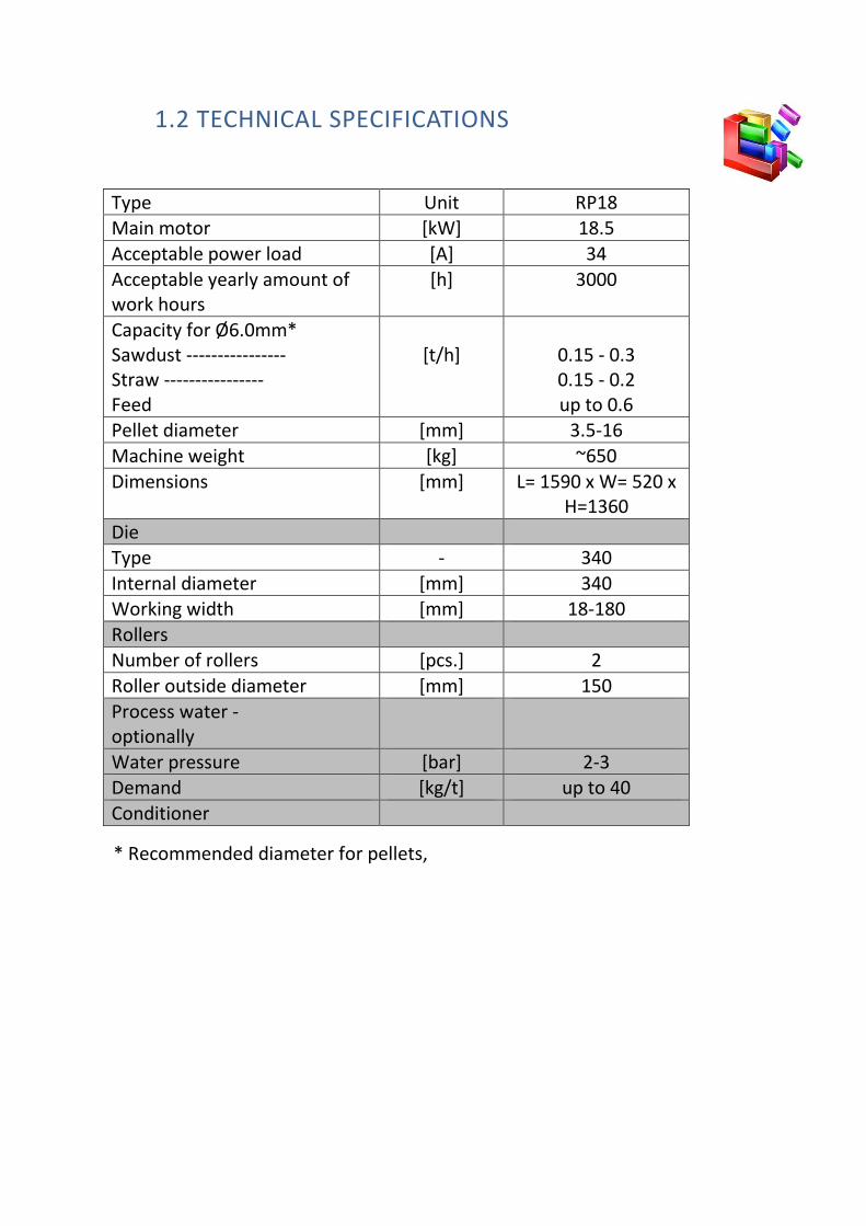
1.2 TECHNICAL SPECIFICATIONS
Type Unit RP18
Main motor [kW] 18.5
Acceptable power load [A] 34
Acceptable yearly amount of
work hours
[h] 3000
Capacity for Ø6.0mm*
Sawdust ----------------
Straw ----------------
Feed
[t/h]
0.15 - 0.3
0.15 - 0.2
up to 0.6
Pellet diameter [mm] 3.5-16
Machine weight [kg] ~650
Dimensions [mm] L= 1590 x W= 520 x
H=1360
Die
Type - 340
Internal diameter [mm] 340
Working width [mm] 18-180
Rollers
Number of rollers [pcs.] 2
Roller outside diameter [mm] 150
Process water -
optionally
Water pressure [bar] 2-3
Demand [kg/t] up to 40
Conditioner
* Recommended diameter for pellets,

2. CONSTRUCTION AND OPERATION RULE
2.1 CONSTRUCTION
The press of the pellet mill is composed of the following components:
• Bearing body,
• Rotary shaft,
• Flat die fi340,
• Holder with two rollers,
• One driving motor with transmission,
• Charging hopper
• Control cabinet with start like
o Star-delta,
o Soft-Start,
o Frequency Inverter.
The press cooperates with the following devices (all optional – not included in
regular price):
• Feeding screw,
• Conditioner,
• Pellets cooler.
2.2 PRINCIPLE OF OPERATION
Pelleting takes place in a pelleting chamber. The chamber contains a
die and two rollers that are responsible for forcing the raw material
in the die holes
The raw material is fed to the pelleting chamber of the pellet mill through a
screen installed inside the charging hopper and a mixer.
The raw material prepared is fed through the charging hopper mounted on the
body of pelleting chamber. Scrapers mounted on roller guides are responsible
for the correct guiding of raw material under the rollers and to the die. The
rollers push the raw material through the holes, form elongated pellets, the
length of which is determined by a pellet breaker shoe. Then they drop out
through the outlet in a lower part of the body.
The production of pellets made of the raw materials that contain ingredients
with a high grindability index and a low content of binding agent results in the
capacity decrease and a rapid wear of pellet mill components.
2.2.1. Die
The die is embedded in the pellet mill body on a rotating shaft and secured with
a wedge against unintentional rotation.
Thanks to the rotary movement of the roller holder over the die, the raw
material is pressed into the die holes. The contents of the raw material and its
formula decide about the design of a die. It is determined by the so-called pile-
up ratio of the die (this is operation length of the operation hole to the pellet
diameter ratio).
The die made of special steel is hard and resistant to abrasion.
2.2.2. Rollers
Rollers force the raw material in the die holes. The roller outside area has arc-
shaped notches (patent) that are a new feature combining in this solution the
advantages of rollers with straight notches with the rollers with drilled holes on
the girth. This solution provides a proper “friction” and helps to force the raw
material in the die, reducing both its slide and the problem of throwing the
medium aside while being forced in the die.

The arch-shaped cuts improve the mating of rollers and a die, increase slightly
the machine capacity in some circumstances and reduce noise. Rollers and die
make a system that has a decisive impact on an operational quality of pellet mill.
2.2.3. Drive
The pellet mill is driven by one electric motor through a cylindrical-conical gear
transmission. The transmission requires oil change according to the operating
time of the transmission and its operating temperature.
2.2.4. Conditioner (OPTIONAL)
In the conditioner, the mixture or the raw material are heated by steam and mixed
with water and/or other substances. An inlet in the conditioner is used for
providing raw material from the feeding screw. In the middle of the conditioner
body, the raw material is constantly
mixed by a rotation shaft with blades
and moved towards the pellet mill
hopper and the pelleting chamber.

2.2.6. Dimensions of the pellet mill
Figure 1. Offer figure of pellet mill type RP18

3. TRANSPORT AND UNLOADING
3.1 LOADING AND TRANSPORT
• Loading optionally with a lift truck that has a lifting capacity of at least 800
kg.
• The lift truck should be equipped with suitable forks with additional
fitting.
• In view of a fact that at the bottom of the pellet mill there is an engine
casing that can be easily damaged, it will be significantly advisable to use
for loading 70cm- long beams of cross section 10x10 cm that should be
placed on forks from the bottom of the frame along the both sides of the
pellet mill.
• The device shall be transported on a truck of suitable load capacity and
properly secured with straps.
3.2 UNLOADING
• Unloading the device can optionally be carried out with the forklift truck
with the relevant forks and an additional protection, with a lifting capacity
suitable to the weight of the lifted pellet mill,
• Unloading shall be made with the utmost caution.

4. INSTALLATION
4.1 GENERAL INFORMATION
The pellet mill should be installed on the basis of technological design of
pelleting line.
A pellet mill is a device that operates together with other machines. For
instance, it is a part of pelleting plant. Thus, the pellet mill is a device that is not
able to fulfil its task alone, in most cases. Only installed in a line together with a
system of raw material preparation, a system of buffer silos, humidifying and
electronic control with a cooler, screen, transport and dust aspiration, the pellet
mill becomes the appliance of a full value.
ATTENTION: The assembly and the installation of the pellet mill can be
performed only by authorised installers designated by the supplier. They should
be experienced and have documents that certify appropriate training.
Before assembling and installing the pellet mill, it is absolutely recommended
to get acquainted with this Manual.
4.2 ASSEMBLY DETAILS
The place where the pellet mill is to be installed and the distance from the walls
or other appliances shall guarantee the access necessary for everyday service
and during the disassembly of its components for repair and service.
4.2.1 ASSEMBLY ON THE STEEL CONSTRUCTION
1. The design of a steel platform shall be developed by the factory designer
on the basis of production engineering guidelines.
5. INSTRUCTIONS FOR USE
5.1 OPERATIONS PRIOR TO THE START-UP
ATTENTION: Any regulating activities connected with operating the pellet mill
and other appliances must be done only after turning off the electricity (main
circuit-breaker, pos. 0). The pellet mill should be started up in the presence of
two service workers.
ATTENTION: Before starting up your pellet mill, prepare a maintenance mixture:
1. Prepare a large tank of minimum volume 0,5m3.
2. Prepare your small fraction raw material (or a mixture) that you usually use for
pelleting.
3. Prepare any vegetable oil (that can also be used).
4. Fill with the material to be pelleted up to approx. 1/3 of the container volume.
5. Pour oil up to 1/3 of the tank volume and mix thoroughly. Attention: Mixture
has to be greasy to the touch.
6. Repeat step 4 and 5 until the tank is full.
More information about Oil Mixture is given in section 5.3.1.6
ATTENTION: Before starting up the pellet mill, always check the following items:
• Die and rollers must be fitted properly,
• Check whether the rollers are correctly positioned in relation to the die,
• Ensure that anchoring bolts are securely attached,
• Check that both pelleting chamber and conditioner chamber are empty,
• Check that the pellet mill safety devices are working properly,
• Check that the rotation direction of pelleting press is in accordance with
arrows marked on the pellet mill body,
• Adjust a pellet cutting knife to the required pellet length,
• Set minimum feeding of raw material by feeder.
In the case of a conditioner:
• Check the steam supply (water as an option) to the conditioner and the
quantity of the processed raw material in a feeding tank, drain a steam
supply system.
Electrical system:
1. Electrical system has factory settings that must not be changed.

2. Changing factory settings can cause mechanical damage of the transmission
(that cannot be repaired under the guarantee).
3. Breaking the seal means loss of guarantee.
5.1.1 SEQUENCE OF STARTING UP
Operational sequence to start up the appliances cooperating with the pellet mill:
1. Transport systems.
2. Cooling.
3. Aspiration.
4. Crushing (feeds only).
5. Screening.
6. Pellet mill
7. Conditioner
8. Screw feeder of raw material.
9. Inlet the steam (or water as an option for biofuels) to a pellet mill
conditioner - as required - gradually while monitoring the main motor
load and the temperature of discharged pellets.
When you have started all the components in the pellet mill, gradually increase
the feeding of raw material into the conditioner, while monitoring the
indications of electric current (they should be from 0.7 to 0.9 of the rated rated
current value specified on the motor nameplate).
Max. 34 Amps Attention: For a stable operation, maximum load of pellet mill should not
exceed 34 Amps. Temporary higher values than 34 amps are also possible,
however, it should be truly instantaneous and take no more than a few
seconds. Otherwise, the operator should close the feeding of raw material into
the pelleting chamber through an openwork regulator on the hopper, so as to
reduce the value of the current below 34 Amps.
The load factor depends on a quality and a type of the pelleted medium and its
impact on a stable operation of pellet mill and on the quality of formed pellets.
5.2 DIRECTIONS FOR USE
5.2.1 GUIDELINES FOR FEEDS
A pelleting line which includes RP 18 must be equipped with cleaning devices
like destoners, magnetic separators, pneumatic transport systems, which
remove impurities.
Water contents of mixture saturated with steam should vary within 16.5 -17.5%
and its temperature shall be within the range 55 – 75oC.
You shall use the steam of parameters optimal for the raw material to be used
and select them experimentally.
Use a steam trap that has to be equipped with a device for draining the
accumulated condensation water from steam lines (it depends on a type of the
used steam generator). Steam pressure used to saturate the mixture to be
pelleted should be between 1.5-4.5 bar, which corresponds to steam
temperature of approx. 110-150oC.
The pellet mill shall be supplied with steam that is stable and reduced by flowing
through the stabilising-reduction system.
Use the steam of parameters optimal for the raw material to be used and select
them experimentally.
This information may vary slightly from the actual optimal parameters. They
should be verified by adapting them to the existing conditions in such a way as
to adjust optimally pelleting parameters to ensure a stable and steady operation
of the machine and achieve the best quality pellets.
5.2.2 GUIDELINES FOR SAWDUST AND STRAW
A pelleting line which includes RP 18 must be equipped with cleaning devices
like destoners, magnetic separators, pneumatic transport systems, which
remove impurities.
Raw material supplied to the pellet mill should be free of impurities such as bark,
pieces of wood (e.g. knots), metal, sand, weeds etc. These impurities may be the
cause of pellet mill break down, which guarantee does not cover.

A particular attention should be paid to the degree of fragmentation and
moisture content in the processed biomass that should not exceed 13% for
sawdust and 15% for straw.
The best operation conditions for the pellet mill are obtained when the humidity
of sawdust is 10.0 - 14.0%, and of straw: 14-15%.
At higher humidities in raw material, the capacity of pelleting process shall be
experimentally reduced in order to improve the quality of pellets.
This information may vary slightly from the actual optimal parameters. They
should be verified by adapting them to the existing conditions in such a way as
to adjust optimally pelleting parameters to ensure a stable and steady operation
of the machine.
5.2.3 THE RAW MATERIAL SIZE
RP 18 was designed to pelletize mash feedstock, before fine ground, with size of
0,1mm – 3,0mm. The particle size depends on the diameter of die holes. In case
of non-standard diameters and raw materials please contact our engineers for
support.
5.3 OPERATION
When the pellet mill is in operation, it is forbidden to carry out any
maintenance work such as: tightening screws, roller adjustment, removing
covers, opening the door of pellet mill, loosening sensors etc.
5.3.1 HANDLING THE DIE
5.3.1.1 DIE ASSEMBLY INSTRUCTIONS
The die is embedded on a seat in the lower body and secured with a wedge
against turning. The die must be set evenly in each place, otherwise this would
induce poor work of the pelleting unit and result in damaging the pellet mill.
ATTENTION: Never perform any maintenance work when the pellet mill is in
motion. You should always first stop the pellet mill and disconnect the power
supply.

1. Ensure that the power supply has been disconnected. (Main Circuit
Breaker, pos. 0)
2. Remove the hopper and the top body.
3. Install the die using a special puller with screws.
4. Install a packing ring.
5. Install a holder with rollers and secure it with a nut.
6. Install the top body and the hopper.

5.3.1.2 DIE DISASSEMBLY INSTRUCTIONS
To mount and dismount a die and a holder with rollers, a special equipment is
used that is included into the pellet mill set.
1. Disconnect electrical power from the pellet mill. (Main Circuit Breaker,
pos. 0)
2. Remove the hopper and the top body.
3. Remove a retaining nut and remove the holder with rollers.
4. Remove the locking screw and the sealing ring.
5. Install the die puller and remove the die.
6. Remove the bearing housing of the die and clean the bearing.
5.3.1.3 THE USE OF A NEW DIE
>> INSTRUCTIONS: START-UP A NEW DIE:
1. Push the rollers to the die.
2. Check that scrapers are installed correctly.
3. Install the hopper.
4. Start the pellet mill.
5. Feed the pelleting chamber will pelleting mixture.
6. Pellet the mixture and discard the produced pellets (NOTE concerning the
food: do not allow this pelleted mixture to enter the pelleting line!).
7. Now it is necessary to fill the pelleting chamber with a small amount of
appropriate pelleting mixture (of raw material).
8. The press starts pelleting. Start increasing the load paying attention on the
readout of the ammeter (max. 34A) on the control panel of the pellet mill.
9. If the die is not jammed, increase the capacity gradually.
Each die supplied by ECOKRAFT AG, before leaving the production line, is
checked i.a. for smooth surface of holes and its hardness. However, during the
first few hours do not overload the die as this may lead to its frequent blockage.

During first 50-70 operation hours, the die is subject to grind in the co-operating
parts and at that time it is recommended to load gradually the pellet mill (the
faster grinding in the lower losses- in specific cases, it is recommended to use
abrasive mixtures that enable the cooperating parts to grind in optimally in a
very short period of time).
The grinding mixture shall be mixed in the following ratio:
• a half of a big-bag filled with raw material to be pelleted
• 10 kg of aloxite (pelleting degree 70)
• 10 litres of oil.
And in the same ratio pass the mixture through dies for 2 to 3 hours.
Always install new rollers with a new die. The installation of old rollers will
damage the new die or cause its accelerated wear as well as the accelerated
wear of bearings in the pellet mill components.
ATTENTION: If a die tends to be jammed, reduce feeding and add quickly a
lubricating mixture to the hopper, or the die should be ground in.
In very rare cases, after an incorrect start of a new die, the holes are clogged
with raw material and the pellet mill is jammed (stained and very hard pellets).
In such case, remove pressed material out of the die by drilling it out. When the
die is damaged (overlapped holes), it should be returned to the supplier for
payable repair.
The dies of hole diameter less than 3 mm require particular attention during the
start-up and they must be ground in.

5.3.1.5 PREPARING THE DIE FOR A LONGER PERIOD OF ITS
STANDSTILL
In the case of planned long standstill of the die (more than 3 hours, and more
than 1 hour in winter), a lubricating mixture should be pelleted at the end of the
pellet mill work (see: Lubrication mixture).
Some of the raw materials or mixtures, in particular, without fat or with its low
content and that have in their formulas: milk powder, whey, chalk and other
media difficult for pelleting, become hard while cooled with the die and
therefore may make the production restart very difficult or even impossible with
the die filled in this way.
If the die holes are jammed, re-drill them or send the die back to ECOKRAFT AG
for regeneration.
5.3.1.6 LUBRICATION MIXTURE
A lubrication mixture is usually a raw material with an admixture of approx. 6 -
10% of any oily substance that reduces friction. It can be vegetable or animal oil.
Old and worked machine oil and others are admissible for biomass.
Such a mixture is more resistant to hardening than the raw material itself, which
is caused by drying.
The addition of lube mixture at the end of the pelleting cycle will make the start-
up easier after a longer period of the pellet mill standstill.
The amount of lube mixture depends on the diameters of the die and working
holes.
FEED ONLY: Before pelleting lube mixture, close the inlet to the cooler. Do not
let the lube mixture get into the devices behind the pellet mill (cooler, screen
etc.).
Attention: In the event of a clogged die, it should be re-drilled with a drill of
diameter slightly smaller than the rated die drill.

5.3.1.7 FACTORS AFFECTING THE DIE LIFE
The die operation life depends on the following factors:
• a design of die, a grade of steel used to make the die,
• a configuration of pelleting line and production technology,
• a type of material to be pelleted (cattle feed, poultry feed, sawdust of
coniferous wood, straw, peat etc.),
• a design of pellet mill, its stiffness and a degree of wear,
• an experience in operating a pellet mill.
Factors that shorten the operation life of dies for animal feed
• Low fat content,
• A large number of components with a high friction degree,
• Lack or wrong parameters of steam supplied to the conditioner,
• Wrongly selected design of a die,
• Incorrect operation.
Factors that reduce the operation life of the die to pellet the biomass
• Improper fragmentation of the raw material to be pelleted,
• The raw material of non-uniform quality,
• A large number of the components with a high degree of friction (sand,
bark, glues).
• Improper humidity of raw material (too dry or too wet),
• Wrongly selected design of a die,
• Incorrect operation.
Mechanical factors that reduce the operation life of the die
• Play on the main shaft of the pellet mill (worn or damaged bearings),
• Bad adjustment of rollers with reference to the die - too much pressure
and rollers touch the die during operation or too large offset from the die,
• Use of worn rollers with a new die,
• Use of a worn die with new rollers,
• Wrong adjustment of at least one scrapper.

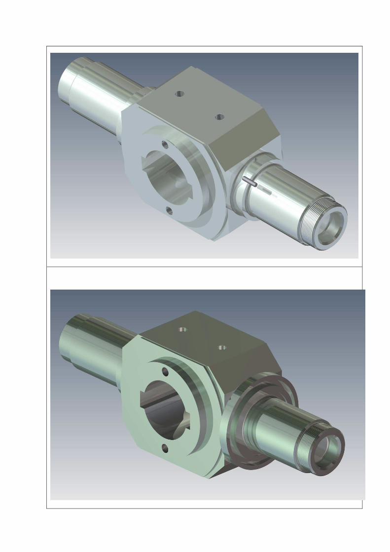
5.3.2 INSTALLING AND REMOVING ROLLERS
ATTENTION: First, disconnect electrical power from the pellet mill. (Main
Circuit Breaker, pos. 0)
Rollers are installed and removed by using an extractor included into the
equipment of the pellet mill.
The holder with rollers shall be inserted onto the shaft of pellet mill and press up
to the die using the tool. Then, a suitable number of spacer washers for a given
die shall be installed and tightened with the nut. The nut must be protected
against intrinsic unscrewing during machine operation by tightening the bolt
located on the nut.
This operation is done after installing the die.
5.3.2.3 SETTING UP THE ROLLERS AGAINST THE DIE
A gap between the rollers and the die allows forming a layer of raw material to
protect the die surface against contacting the rollers. Using a feeler gauge, set
the rollers from 0.05 to 0.1mm from the die surface, depending on the needs.
The distance between the rollers and the die is adjusted manually by a very
simple control system using two lock nuts.
Once the die - roller distance (0.05 -0.1mm) is set, lock the lower nut with one
hook wrench and tighten the upper nut with another wrench.
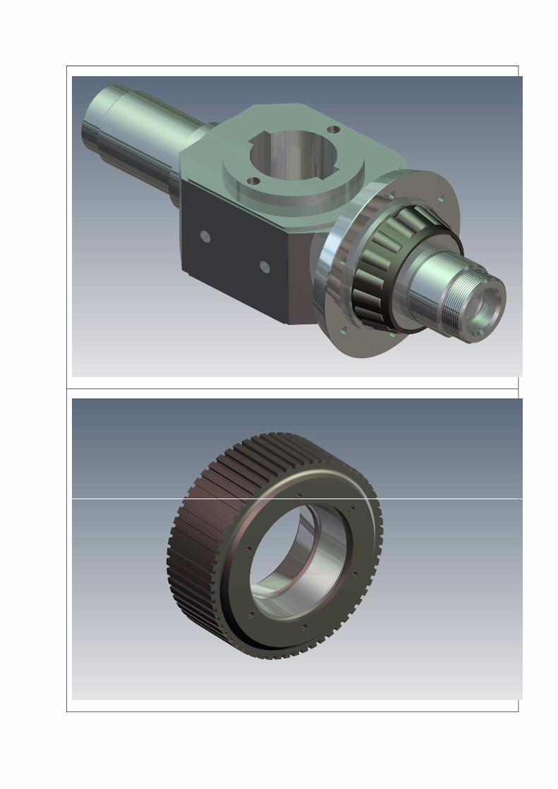
5.3.3 REPLACING ROLLERS JACKETS
5.3.3.1 REMOVING ROLLER JACKETS
1. Loosen 12 pieces of Allen screws M6x20 that hold the cover.
2. Remove the cover no. 3 with a lubricator.
3. Remove both a nut and a crown washer.
4. Using the puller, remove the roller jacket and bearing.
5. When replacing roller jackets, it is not necessary to remove cover nos. 1 and 2
6. Using the instrument, push out the outer rings of bearings with their spacer
ring out of the roller jacket (similarly, repeat this operation on the other side).
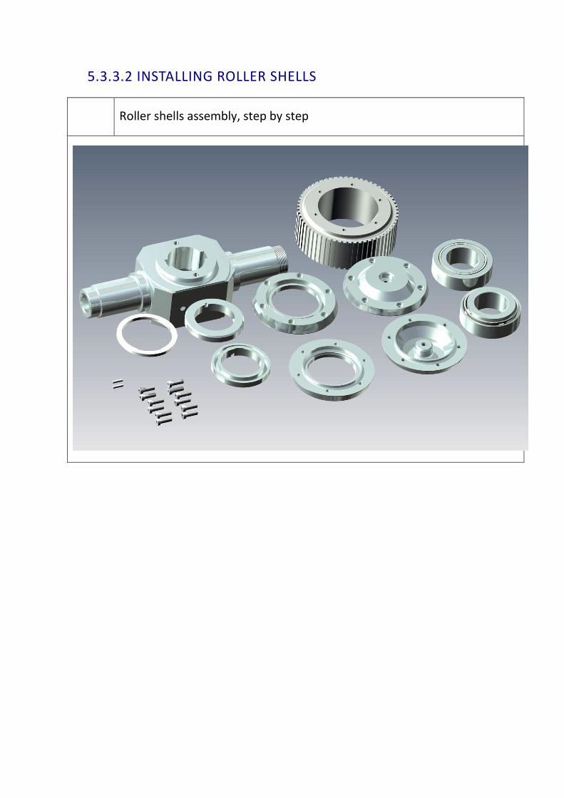
5.3.3.2 INSTALLING ROLLER SHELLS
Roller shells assembly, step by step


1. Installation of shear pins before turning cover no. 1.
2. After pinning, install cover no. 1, on which cover no. 2 is mounted (similarly,
repeat this operation again on another side of the roller).
3. Then, roller holders shall be pushed onto the shaft.
4. Hammer outer rings of bearings onto the centre of roller jackets keeping in
mind the spacer ring between the bearing rings.
5. Put the prepared roller jackets with installed outer rings of bearings on the
shaft of the roller holder with the pushed earlier bearing.
6. The second bearing is mounted and pushed up to the moment of free turning
of bearing barrels.
7. Install crown washer and tighten the whole with nuts.
8. Washer is locked.
9. Put on cover no. 3 with previously screwed lubricator.
10. Screw the whole with Allen screws M6x20-12 pcs.
11. Then, use lubricator to force grease to fill the inside of a roller until grease
appears between the shaft and the covers.
5.3.4 SCRAPERS IN PELLETING CHAMBER
ATTENTION: First, disconnect electrical power from the pellet mill. (Main
Circuit Breaker, pos. 0)
Each roller has its own scraper, the task of which is to direct raw material under
the roller. The individual scrapers are adjusted in a correct position for each
roller.
5.3.5. SETTING SCRAPERS
While setting, secure a 2 - 4mm gap between scrapers and die surface.
The medium to be pelleted should be directed towards the centre of the roller
track where the rollers contact the die. The optimum set-up of rakes shall be
determined experimentally. Good setting of rakes and their profile reels for a
given medium will make it possible to optimise the capacity of pellet mill and will
improve its operation (less noise and less vibration).

5.3.6 ADJUSTING THE PELLET CUTTING KNIFE
ATTENTION: Make adjustment of the pellet cutting knife on the locked pellet
mill.
• A correct setting of the pellet cutting knife shall be adjusted when an
optimum capacity of the pelleting process is achieved - be careful while
changing the position of the pellet cutting knife when checking the length
of pellets.
• For biofuels, the pellet cutting knife may be retracted entirely or set to
approx. 15-25 mm.
ATTENTION: The pellet cutting knife cannot touch the die when the pellet mill
is in operation.
The length of pellets depends on a distance between the die and the arm of the
pellet cutting device and on the capacity of the pellet mill. Standard length of
pellets for feed is equal to 1.5 - 3.0 of its diameter.

5.4 TROUBLESHOOTING
In the event of a fault, before contacting customer service, first try to
resolve the problem independently.
The following table will help you to do this.
Item Problem Cause Solution
1.
No power on the
pellet mill!
No raw material in the
pellet mill buffer tank (it
concerns fully automatic
mode).
Refill the buffer tank above its
minimum.
Failure of level sensor in the
pellet mill buffer tank (it
concerns fully automatic
mode).
Check and replace the sensor, if
necessary.
Active alarm on your
computer (for full automatic
mode)
Reset the alarm and enter it into
the failure log.
Emergency ”STOP” of pellet
mill is active
Turn off the emergency "STOP"
Power cubicles Check thermal circuit-breakers.
Check fuses.
Not turned on all pelleting
line devices(for full
automatic mode).
Check that pellet receiving devices
are in operation.
Interlock - emergency stop Unlock the emergency stop.
Mechanical lock between
the die and rollers
Check whether the pressed raw
material or other foreign elements,
e.g. metal is between the roller
and the die and remove it; in the
case of any difficulty with the
removal of raw material, apply a
one-touch pulse start in the
opposite direction or loosen the
holder with rollers.
2. Pellet mill difficult
or impossible to
start up
The die of wrong
parameters or not ground in
Check die parameters or grind it in
(mixture 50kg of sawdust (bran) +
6-10 l of (machine) vegetable oil +
10-15kg of white aloxite with grain
size: 50-60).
Metal pressed in the die Remove metal or send the die for
regeneration.
Paired rollers Move the rollers away to leave the
gap 0.05- 0.1mm.
Damaged roller Replace the set of rollers.

Damaged thrust bearing of
rotary shaft (broken)
Call for service.
Overload of the pelleting
set with too much amount
of fed raw material,
Reduce the quantity of fed raw
material.
Raw material of parameters
different than required has
been introduced into the
die.
Check raw material (whether there
is a change of species, fraction -
dust).
3.
Pellet mill suddenly
stops or vibrates
Damaged thrust bearing or
roller bearings.
Failure of the transmission
Call for service after the inspection.
Improper fraction of the
raw material to be pelleted.
Check screens and hammers of
hammer shredders; replace
immediately, if worn, and order at
least one new original set.
3.1 Audible noise
(ticking) with each
rotation of die
Metal pressed into the die.
Misaligned or worn
scrapers.
Remove, by striking or
drilling out.
Adjust or replace.
3.2 Press does not
produce pellets
• Too much fat in the
mixture.
• Change of recipe or raw
material.
• Poorly chosen die to the
medium to be pelleted (raw
material).
• Damaged die
(jammed).
• Worn rollers and die.
• Too much clearance
between rollers and die.
• Large vibrations of pellet
mill.
• Voltage drop in the line of
electric power supply.
• Poorly tightened wires in
the main motor junction
Change the recipe, move rollers
out of the die gradually in steps of
0.5mm.
Install a die suitable for the recipe
with a correctly selected hole
diameter and operating thickness
(compression ratio).
Check and replace - identify the
compression ratio.
• Order the regeneration.
• Replace.
Set the rollers correctly.
• A poorly chosen die for a given
medium or the die is not ground in,
roller bearing slackness (worn
bearings).
• Check the phase voltage and
voltage between the wires).
• Tighten and check the wiring for
overheating; replace, if necessary.

box, on the contactor or
faulty wiring.
4. Low quality of
pellets
(soft pellets, too
large amount of
crumbled pellets)
BIOMASS: Improper
humidity of the raw
material to be pelleted.
Check the moisture of raw material
after leaving the dryer or at the
inlet of the production line in
charging crushers; then, adjust the
humidity of raw material and fix it
at the level of 12% + /- 1%
(experimentally).
Misaligned or worn rollers. Check the alignment, replace worn
rollers.
Worn or damaged die
(overlapped holes of die).
Replace or order regeneration.
Improperly selected
compression ratio of the die
for the raw material to be
pelleted.
Check and replace or change raw
material (recommended mixture).
Worn rollers and die. Replace rollers and die into new
ones (do not replace rollers or a
die - replace the entire set); order
immediately at least one new
original set of consumable
materials.
Poorly chosen parameters
of raw material to the
mounted die.
Raw material too thick - frayed,
short pellets, much crumbled
pellet material.
Raw material too wet - frayed,
short pellets, much crumbled
pellet material.
Change of raw material type or
change of the proportion in a
recipe, contamination of raw
material with sand, adhesives or a
significant quantity of bark (check
the ash contents in the sample - <
1.2%)
Too much medium feeding. Reduce the quantity of fed raw
material.
Worn scrapers or set
incorrectly.
Adjust or replace worn scrapers
into the new ones; you must
immediately order at least one
new original set of scrapers.
Too low compression ratio. Apply a die with holes that have a
longer working part.
4.1 Burnt pellets. Too low humidity. Determine the correct humidity at
stable level.
Too high
temperature of
pelleted material.
Too high current
consumption.
(very hard pellets)
Poorly chosen parameters
of raw material for the
mounted die.
Dusty raw material - dark pellets
(brown and burnt).
Over-dried raw material - dark
pellets (brown and burnt).
Contamination of raw material
with sand, adhesives or a
significant quantity of bark (check
the ash contents in the sample - <
1.2%)
Partly overlapped holes of
die.
Regenerate or replace the die.
Change of the raw material
parameters (different type
and quantity of the raw
material components,
pollution).
Apply an additional component.
Provide the raw material designed
for the installed die or change the
die into the one adapted to the
new raw material.
Small feeding of medium. • Accelerate medium feeding, at
the same time, add the mixture of
pellets and oil through the access
door in the hopper.
Too high compression ratio. • Apply a die with holes that have a
shorter working part.
4.2 There is a smoke
that escapes from
the pellet mill
(burning)
• Damaged bearings.
• Poorly chosen die to a
given medium.
• Damaged or wrong grease
lubrication system.
• Worn scrapers.
• Check and replace - call for
service.
• Check the compression ratio or
change the medium (recipe).
• Check and replace.
5.
Poor capacity of
pellet mill
Incorrectly set scrapers. Adjust properly the scrapers.
Wrongly selected die. Check and replace (compression
ratio too high).
Change the parameters of raw
material (increase the volume of
fraction).
Misaligned rollers. Adjust the gap between rollers and
die (0.1-0.4 mm).
Too low temperature of raw
material fed onto the die.
Raise the temperature above 30ºC.
Too dusty raw material. Replace the screens in the crusher
for larger mesh.
Change in properties of
used raw material.
Check and replace or modify used
raw material (recommended
mixtures with fixed proportions of
the individual components of raw
material).

The change in properties of
used raw material induces
the increase or decrease in
the capacity of pellet mill.
When the capacity is increased,
the formed pellets are longer.
When the capacity is decreased,
the formed pellets are shorter.
Stabilize the capacity and adjust
the pellet cutting knife in order to
obtain the pellets of optimal length
( 2-3 diameters for feed, and 10 -
40 mm for biofuels).
5.1 Press often gets
jammed
• Worn scrapers of raw
material that produce an
uneven layer of the
processed medium under
the rollers.
• One or more rollers lock
(seizing).
• Too much clearance
between rollers and die.
• Worn rollers or die.
• Too much moisture
content in the processed
medium.
• Scrapers of raw material
are improperly adjusted
inducing an uneven
distribution of the
processed medium under
the rollers.
• Variable parameters of
the pelleted medium.
• High moisture content in
the processed raw material.
• Replace.
• Check and replace.
• Decrease the distance.
• Replace.
• Reduce the moisture.
• Adjust the scrapers in their
correct position.
• Check that the parameters are
consistent with the designed ones.
• Reduce the moisture, add a
component (e.g. CaO or halloysite
sorbent up to 3% - for biofuels
only)
6. Accelerated or
uneven wearing of
rollers, the die,
scrapers or other
parts of the pellet
mill and other units
of the pelleting line.
Small load of the pellet mill. Increase feeding.
Wrongly selected die. Determine a correct compression
ratio for the processed raw
material.
Improperly adjusted rollers. Adjust the rollers with reference to
the die according to the Manual.
Poorly positioned scrapers
or worn.
Adjust or replace.
Raw material contaminated
with sand, glues, with
plenty of bark, etc.
Check the ash content in the
processed raw material (allowable
level of ash content < 1.22%),
optimal: 0.8%, and ideal up to
0.55%.
Metal debris moulded in the
die.
Check and clean all magnetic
separators installed on tanks.
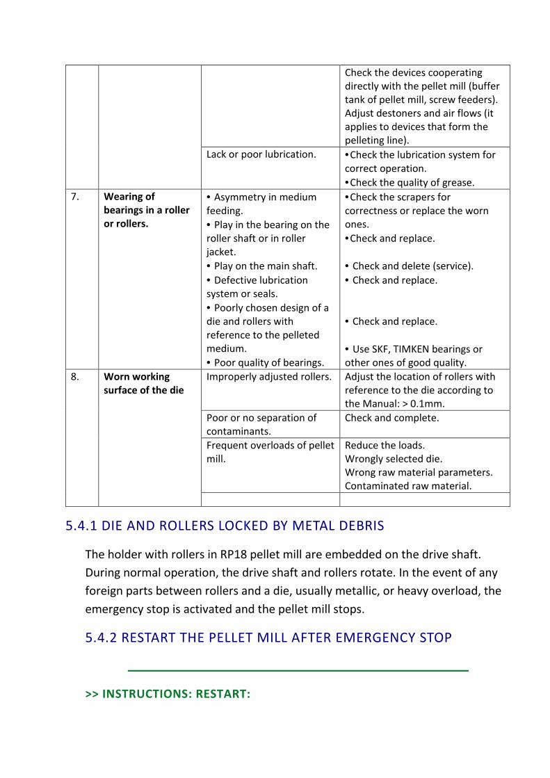
Check the devices cooperating
directly with the pellet mill (buffer
tank of pellet mill, screw feeders).
Adjust destoners and air flows (it
applies to devices that form the
pelleting line).
Lack or poor lubrication. •Check the lubrication system for
correct operation.
•Check the quality of grease.
7. Wearing of
bearings in a roller
or rollers.
• Asymmetry in medium
feeding.
• Play in the bearing on the
roller shaft or in roller
jacket.
• Play on the main shaft.
• Defective lubrication
system or seals.
• Poorly chosen design of a
die and rollers with
reference to the pelleted
medium.
• Poor quality of bearings.
•Check the scrapers for
correctness or replace the worn
ones.
•Check and replace.
• Check and delete (service).
• Check and replace.
• Check and replace.
• Use SKF, TIMKEN bearings or
other ones of good quality.
8. Worn working
surface of the die
Improperly adjusted rollers. Adjust the location of rollers with
reference to the die according to
the Manual: > 0.1mm.
Poor or no separation of
contaminants.
Check and complete.
Frequent overloads of pellet
mill.
Reduce the loads.
Wrongly selected die.
Wrong raw material parameters.
Contaminated raw material.
5.4.1 DIE AND ROLLERS LOCKED BY METAL DEBRIS
The holder with rollers in RP18 pellet mill are embedded on the drive shaft.
During normal operation, the drive shaft and rollers rotate. In the event of any
foreign parts between rollers and a die, usually metallic, or heavy overload, the
emergency stop is activated and the pellet mill stops.
5.4.2 RESTART THE PELLET MILL AFTER EMERGENCY STOP
>> INSTRUCTIONS: RESTART:

After an emergency stop, perform the following steps:
1. Switch off the power supply.
2. Dismount the hopper.
3. Remove the upper body.
4. Loosen and slide the rollers as far away as possible from the die.
5. Determine a cause of the blockage and remove it. If this is a foreign metal
part, remove it and check the condition of rollers and the die. When the
internal surface of the die is damaged significantly by foreign objects, it
should be sent to ECOKRAFT AG for regeneration. If there is a stop due to
overloading the feeding hopper with raw material, clean the pelleting
chamber of the excess of raw material to be pelleted.
6. Adjust rollers in their correct location (see: Setting rollers).
7. Install the top body and the hopper.
8. Reset the alarm (computer control).
9. Start the pellet mill.
5.5 LUBRICATION
5.5.1 LUBRICATION OF PELLET MILL
We recommend the following lubricants to be used:
• Modex Oil - VECOPLEX EP-2/320.
• Klueber Stabutherm - STABUTHERM GH 461,
• Klueber Stabutherm - KLUBRFOOD - NH1 64-422 (for feed - the contact
with food),
The following mechanisms of the pellet mill are subjected to lubrication:
• Bearings of the rollers,
• Rolling bearing of the die,
• Thrust bearing.
5.5.3 MANUAL LUBRICATION
5.5.3.1 MANUAL LUBRICATION OF ROLLER BEARINGS
Lubricate the roller bearings with the grease mentioned above.
This operation is done by forcing grease into the lubricating nipples located in
the caps of rollers. The access to them is obtained after stopping the pellet mill
and removing the top body (about 30-40g. for each nipple).
Attention: Particular attention should be paid to the fact that the old, used
grease with a dim colour is to appear on the other side of the lubricated roller.
It means that grease has been properly distributed to all recesses of the
lubricated roller.
In the case when the grease does not appear while lubricating, immediately
check the ball nipple and the lubricator.

Schedule of manual lubrication of roller bearings
Item Medium/Type of pellet mill Frequency of lubrication
1. Feed; RP18 Every 4 - 6 operation hours
2. Biomass; RP18 Every 2 - 3 operation hours
5.5.3.2 MANUAL LUBRICATION OF THRUST BEARING
Main shaft thrust bearing shall be lubricated every 50-60 operation hours with
grease mentioned above by forcing the grease into the ball nipple (in amount of
50 - 60 g) located on the outside of the bottom body.
• Attention: Particular attention should be paid to the fact that the old,
used grease with a dim colour is to appear on the shaft.
• It means that grease has been properly distributed to all places to be
lubricated.
• In the case when the grease does not appear while lubricating,
immediately check the ball nipple and the lubricator.
5.5.3.3 LUBRICATING THE ROLLING BEARING OF THE DIE
The rolling bearing of the die shall be lubricated every 4-6 operation hours with
grease mentioned above by forcing the grease into the ball nipple (in amount of
20 - 30 g) located on the outside of the bottom body. The access to it is obtained
after stopping the pellet mill and opening the outlet chute of pelleted material.
• Attention: Particular attention should be paid to the fact that the old,
used grease with a dim colour is to appear on the shaft.
• It means that grease has been properly distributed to all places to be
lubricated.
• In the case when the grease does not appear while lubricating,
immediately check the ball nipple and the lubricator.

Schedule of lubricating the pellet mill components
Item Lubricated part Frequency/Quantity Grease
1. Bearings of rollers: Feed: Every 4 - -6 operation
hours/30-40g.
Berutox, Vecoplex,
Stabutherm
2. Bearings of rollers: Biomass; Every 2 - 3 operation
hours/30-40g.
Berutox, Vecoplex,
Stabutherm
3. Shaft thrust bearing Every 50 - 60 operation
hours/50-60g.
Berutox, Vecoplex,
Stabutherm
4. Rolling bearing of the die Every 5 - 6 operation
hours/
20-30g
Berutox, Vecoplex,
Stabutherm
5.5.4 MAINTENANCE
An adequate service and maintenance allow you to keep your pellet mill in good
condition, to achieve optimal working conditions and reduce a risk of the
occurrence of problems.
Provide enough space around the pellet mill while designing a pelleting line and
during a pellet mill installation.
5.5.5 CLEANING
It is crucial to maintain the cleanliness of all rotating parts of the pellet mill. Clean
them thoroughly in appropriate time periods.
• You can use compressed air for cleaning. Do it with extreme caution because
the residues in e.g. the pelleting box can injure your eyes and unwanted
metal parts may cause serious injures.
• Use personal protective equipment!
• At least once a week, with the use of air compressor, clean and purge the
motor casing located at the bottom of the pellet mill. This will help to
remove the embedded dust and restore normal operation of the motor.
• Note: an excess of the collected dust on the motor casing at high
temperatures may cause spontaneous combustion, expose to the
destruction of the device and deprive of the warranty!
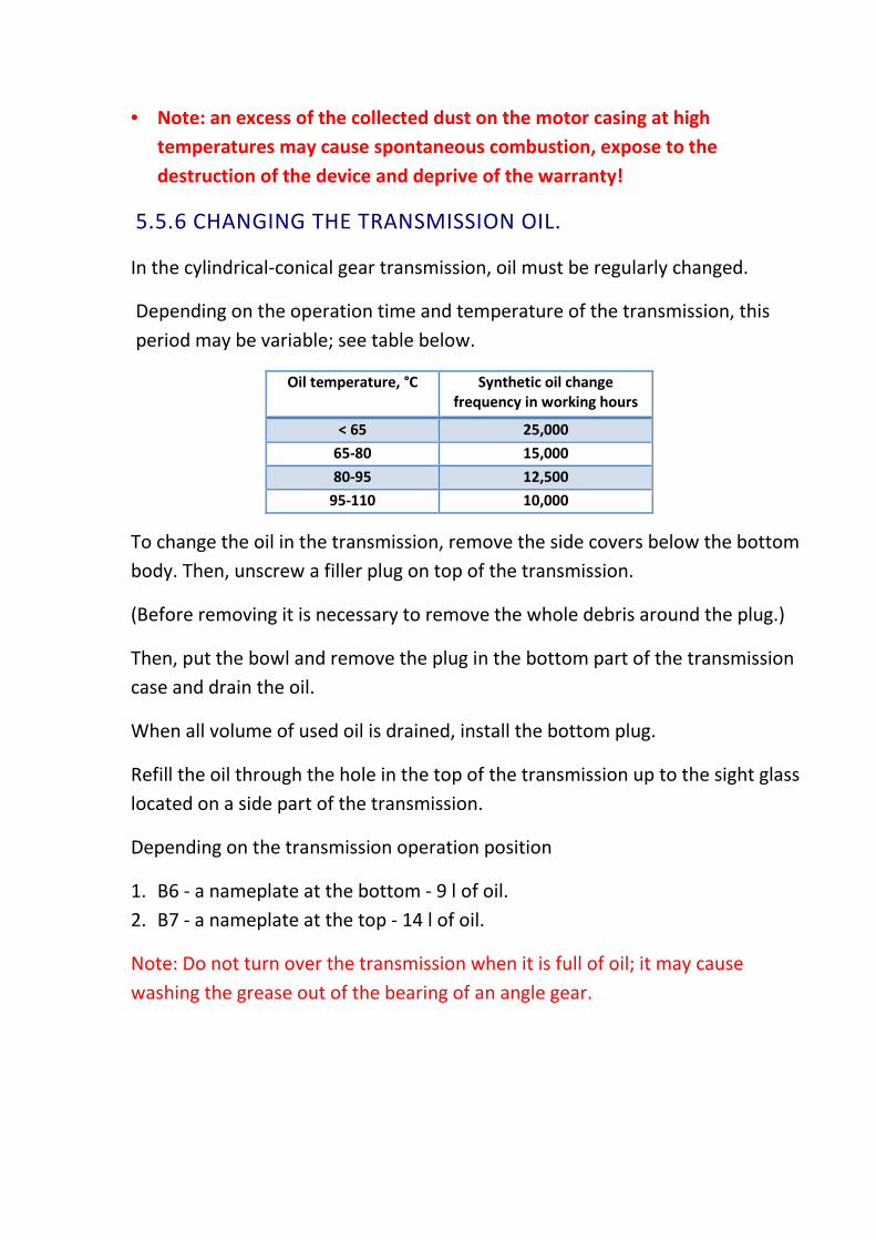
5.5.6 CHANGING THE TRANSMISSION OIL.
In the cylindrical-conical gear transmission, oil must be regularly changed.
Depending on the operation time and temperature of the transmission, this
period may be variable; see table below.
Oil temperature, °C Synthetic oil change
frequency in working hours
< 65 25,000
65-80 15,000
80-95 12,500
95-110 10,000
To change the oil in the transmission, remove the side covers below the bottom
body. Then, unscrew a filler plug on top of the transmission.
(Before removing it is necessary to remove the whole debris around the plug.)
Then, put the bowl and remove the plug in the bottom part of the transmission
case and drain the oil.
When all volume of used oil is drained, install the bottom plug.
Refill the oil through the hole in the top of the transmission up to the sight glass
located on a side part of the transmission.
Depending on the transmission operation position
1. B6 - a nameplate at the bottom - 9 l of oil.
2. B7 - a nameplate at the top - 14 l of oil.
Note: Do not turn over the transmission when it is full of oil; it may cause
washing the grease out of the bearing of an angle gear.

Photo of the nameplate and the plug.

5.6 CONDITIONS ENABLING THE FULL USE
A full use of all the possibilities of the subject of this Manual requires the
following conditions to be met:
1. Conducting service by trained and authorized persons.
2. Strict adherence to the recommendations of this Manual (DTR).
3. Good organization of the production.

Every 4-6 hours 30-40 g
Feed
Every 2-3 hours 30-40 g
Biomass
Every 5-6 hours 20-30 g
Every 50-60 hours 50-60 g
Every 4-6 hours 30-40 g
Feed
Every 2-3 hours 30-40 g
Biomass
5.7 TOTAL PRODUCTIVE MAINTENANCE - TPM
Full availability of the device is dependent upon the implementation of at least
basic elements of e.g.: machine stock management, TPM (total productive
management).
ECOKRAFT AG organises closed training of TPM for the top management staff:
directors of factories, foremen and operators.
The implementation of TPM significantly reduces the amount of downtimes due
to failures, which, in turn, increases an average number of operating hours and
an average capacity. And this induces directly the higher profits.
In practice, TPM is designed primarily for Maintenance staff [DUR].
DUR (Maintenance Department) is necessary for each factory that has some
production machines.
5.7.1 INSPECTIONS AND MAINTENANCE
The following checks are to be performed.
Item Subject of check Period
1. Current inspections daily
2. Periodic inspections (extended) 2 - 4 weeks
3. Preliminary repair Not applicable
4. Medium repair Every 12 months
5. Extended repair Not applicable
Attention: Period determines the maximum time interval between individual
inspections. Negligence to provide inspections might be a cause of downtimes
not covered by the guarantee.
Attention: To make the repair, the User arranges the Service Team to make the
repair within 10 months from the date of the start-up. Periodic repair is a
payable service (current prices will be presented on the acceptance document of
periodic repair).
5.7.1.1 SCOPE OF CURRENT CHECKS
5.7.1.2 SCOPE OF PERIODIC CHECKS
5.7.1.3. SCOPE OF MEDIUM CHECKS
5.8 --
-
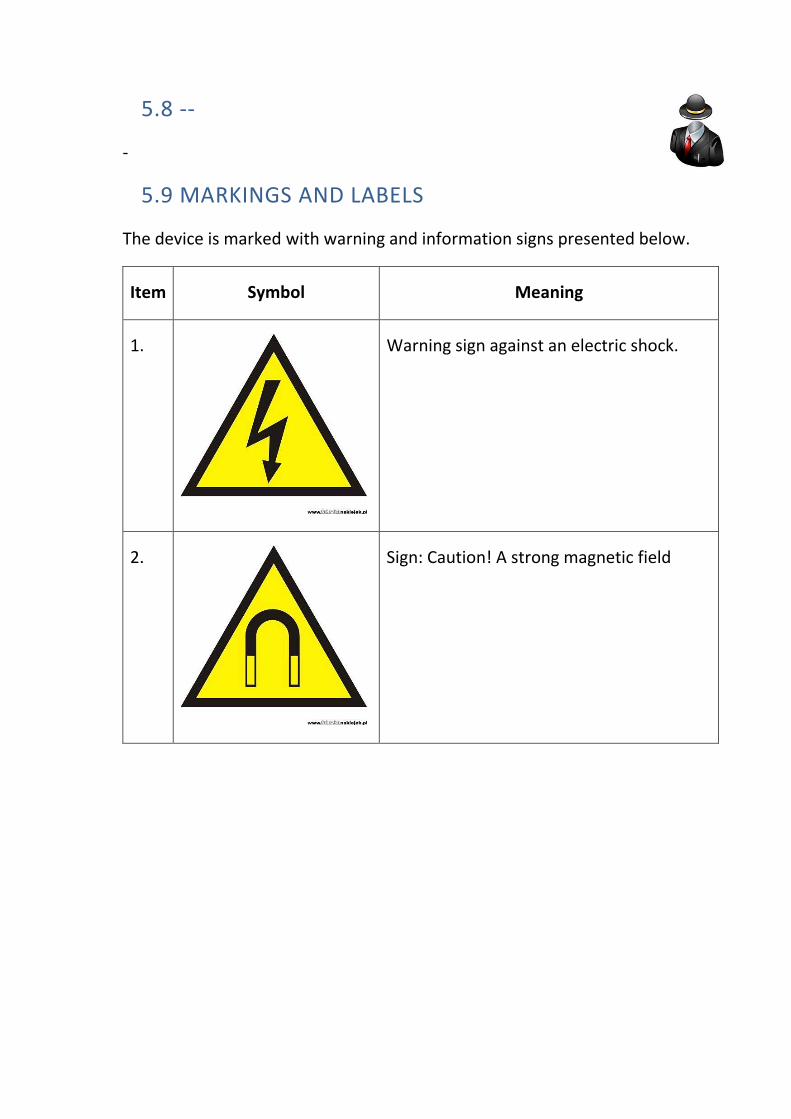
5.9 MARKINGS AND LABELS
The device is marked with warning and information signs presented below.
Item Symbol Meaning
1.
Warning sign against an electric shock.
2.
Sign: Caution! A strong magnetic field
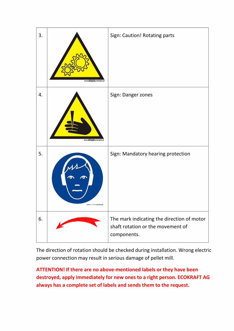
3.
Sign: Caution! Rotating parts
4.
Sign: Danger zones
5.
Sign: Mandatory hearing protection
6.
The mark indicating the direction of motor
shaft rotation or the movement of
components.
The direction of rotation should be checked during installation. Wrong electric
power connection may result in serious damage of pellet mill.
ATTENTION! If there are no above-mentioned labels or they have been
destroyed, apply immediately for new ones to a right person. ECOKRAFT AG
always has a complete set of labels and sends them to the request.

6. OCCUPATIONAL HEALTH AND SAFETY
• While servicing the product, generally known and applicable occupational
health and safety regulations shall be observed.
• Before the start up of the product, all covers should be installed and
secured.
• All the protections against electrical shock shall be kept in an adequate
state.
• Do not let your employees operate the device if they have not been
acquainted with its design and operation.
• Always turn off the main supply of the appliance while performing the
works other than operating the pellet mill (e.g. cleaning, lubrication,
component assembly or disassembly), using the Main Circuit Breaker,
pos. 0.
• It is prohibited to deactivate safety sensors. If any sensor is defective,
replace it immediately!
6.1 RULES OF SAFETY AT WORK
Submitting the instructions contained in this Manual allows you to avoid
accidents at work. The safety instructions must be read and understood by each
user of the pellet mill.
The use according to the directions contained in this Manual and general
operating rules of mechanical devices provide safe work with the pellet mill.
Pellet mill has many moving parts that rotate with high speeds (a die, rollers,
motors, a shaft), and a few high-voltage ports and high-temperature
components, which when used incorrectly can cause serious injuries, or even
death.
Therefore, all work associated with the maintenance and operation of pellet
mill can only be carried out by trained and experienced staff after
disconnecting the power supply (current, steam).

6.2 WARNINGS
1. High voltage and moving parts can cause severe personal injuries and even
death. Always disconnect the power supply before you begin any service
work.
2. Rapidly rotating components may cause severe personal injuries. Always
disconnect the power supply before you begin any service or maintenance
work.
3. For safety, the door of pelleting chamber is equipped with a safety switch.
If you try to open the door, it automatically cuts off the main power supply
of pellet mill.
4. Never attempt to deactivate mechanically or in any other way the safety
switches!

6.3 CHECKING SAFETY DEVICES OF PELLET MILL
The pellet mill is equipped with sensors that ensure the safety work and
operation of the pellet mill.
Hazardous components (e.g. drive belts, rotating intermediate drive shafts,) are
protected with covers that can be removed, if necessary.
Only authorized personnel shall have the right to remove the cover after
disconnecting the electric power supply.
On covers there are placed suitable labels with the information about the
hazard.
Service activities on the pellet mill shall be carried out with full safety
protection at work.
• Close-fitting protective clothing,
• Safety goggles,
• Ear protection,
• Dust mask,
• Special care.
7. LIST OF SPARE PARTS
1. Frame of pellet mill 1 pc.
2. Motorreducer A602 UH60 10,3 P180 18.5kW 1 pc.
3. Bottom body 1 pc.
4. Top body 1 pc.
5. Hopper set 1 pc.
6. Pellet outlet 1 pc.
7. Rollers sight glass 1 pc.
8. Tool box 1 pc.
9. Control box 1 pc.
10. Transmission guard 1 pc.
11. Motor guard 1 pc.
12. Set of swivel wheels 4 pcs.
13. Fastening of bottom body GN 851-320-T2 3 pcs.
14. Fastening of top body GN 851-160-T2 3 pcs.
15. Main shaft 1 pc.
16. Thrust bearing washer 1 pc.
17. Thrust bearing holder 1 pc.
18. Rake 1 pc.
19. Bottom 1 pc.
20. Scraper 1 pc.
21. Pellet cutting knife 1 pc.
22. Roller bearing holder 1 pc.
23. Die 1 pc.
24. Sealing ring 1 pc.
25. Sealing sleeve II 1 pc.
26. Sealing sleeve I 1 pc.
27. Roller holder 1 pc.
28. Roller jacket 2 pcs.
29. Cover I 2 pcs.

30. Cover II 2 pcs.
31. Labyrinth 2 pcs.
32. Scraper 2 pcs.
33. Rake holder 1 pc.
34. Lube tube 1 pc.
35. Motoreducer fastening 2 pcs.
36. Thrust bearing 29414 1 pc.
37. Sealing ring AO130x160x15 1 pc.
38. Sealing ring AO 70x90x10 1 pc.
39. Roller bearing of die NU2211 1-pc.
40. Sealing ring AO 70x90x10 1 pc.
41. Sealing ring A 65x85x10 1 pc.
42. Graphite packing cord 8x8 L=350 1-pc.
43. Bearing for roller 4 pcs.
44. Bearing 2 pcs.
45. O-ring 70x3 1-pc.
46. Nut 1 pc.
47. Spacer 1 pc.
48. Inlet 2 pcs.
49. Roller lube nipple M8x1 2 pcs.
50. Roller bearing lube nipple M8x1 1 pc.
51. Thrust bearing lube nipple M10x1 1 pc.

7.4 STRUCTURE OF ORDER FORM FOR SPARE PARTS
When ordering spare parts please be sure to include the following:
• Device type,
• Serial number,
• Number of spare parts,
• Part number and name of the spare part.

7.4.1 GENERAL ARRANGEMENT DRAWING


8. SERVICE
IN CASE OF ANY PROBLEMS, PLEASE CONTACT THE SERVICE CENTRE
• Phone: +49 991 270912 0
• Fax: +49 991 270912 29
Attention: Fax or email all your claims at: [email protected]

9. TPM AND MAINTENANCE DEPARTMENT
All production employees shall get acquainted with this document.
The staff of the Productive Maintenance Department must absolutely know the
content of the present document.
The necessary condition of free warranty within the warranty period is
mandatory implementation of vital components of the continuous production -
TPM (Total Productive Maintenance). We recommend you to implement the
entire TPM.
If your company does not have a maintenance department, it must be
immediately established. The lack of this department may be the ground for
depriving of the guarantee laws.

10. GUARANTEE
General terms and conditions
1. ECOKRAFT AG grants the User a free 12-month guarantee for the machinery
and equipment manufactured by them.
2. The guarantee period for machinery and equipment not manufactured by
ECOKRAFT AG is determined on the original guarantee cards of their
manufacturers or suppliers.
3. The start of guarantee period for machinery and equipment manufactured by
ECOKRAFT AG is determined on the date of issuing VAT invoice.
4. This guarantee does not cover normal wear of the elements of the subject of
the Contract such as: a die, complete rollers and their components, bearings,
safety pins, contactor coils etc. and the parts worn due to defective operation
of the devices.
5. The guarantee does not cover:
a. any damage or malfunction caused by: improper use or misuse of the
product, negligence of customer, use of the product not in accordance
with this Manual (DTR) or health and safety regulations, or the operation
or service by unauthorised persons,
b. defects resulting from processing media (such as raw materials) that are
not in accordance with this manual (DTR ) or contaminated media (e.g.
raw materials),
c. mechanical damages of products and defects caused by them,
d. any damage or malfunction resulting from fire, flood, or other natural
disasters, war or civil unrest, unforeseen accidents, normal wear in
service, or other external factors,
e. failures and faults resulting from modifications, changes, tuning, repair
and maintenance work by unauthorized persons,
f. operations provided in the operating manual or in the contract which are
to be implemented by the User himself and at his own expense, such as:
maintenance defined in the operational and maintenance manual (DTR)
and other works resulting from the implementation of TPM.
g. all adjustments and maintenance as described in the operator's manual.
6. The User is obliged to report immediately any defects or faults of the subject
of the Contract to the premises of ECOKRAFT AG Company. The notification
must be submitted in writing in German and sent at the fax number +49 991
270912 0 within a period of not more than 6 (six) hours from the date of the
problem occurrence.
7. ECOKRAFT AG declares that they will start to remove faults and defects of the
subject of the contract within 5 working days from the date of the notification
of the occurrence.

8. The Parties agree that without the prior written consent of ECOKRAFT AG the
User is not authorized to remove any defects as a substitute for the Guarantor,
on his cost and risk.
9. In the case of non-compliance with the Operational and Maintenance Manual
(DTR), which shall be supplied to the User, the Guarantee will be cancelled.
GUARANTEE TERMS FOR COMPONENTS MANUFACTURED OR PROVIDED BY THIRD
PARTIES
1. Components and services produced or provided by third parties are covered by
the original guarantee of the manufacturer or supplier.
2. All claims for guarantee, service and other complaints shall be directly reported
by the User to their manufacturers.
3. Cost of services not covered by the guarantee shall be directly specified by the
User individually with the third party.
COSTS OF PAID GUARANTEE AND NON-GUARANTEE SERVICES
1. Any groundless call for guarantee service during the guarantee period will be
treated as payable service - not covered by the guarantee.
2. After elapsing the guarantee period, the cost for each commenced working
hour shall be consistent with the official prices of ECOKRAFT AG.
3. Service operations associated with cleaning, maintenance and periodic
adjustment of the device shall be done at User's expense.
CONSUMABLES AND SPARE PARTS
1. ECOKRAFT AG shall provide the User with consumables of appropriate quality.
2. A lead time for some consumables may be even a few months, e.g.: dies for
pellet mills.
3. The User is obliged to place his order for consumables and spare parts well in
advance.
4. The use of any non-original spare parts and/or consumables is tantamount to
the loss of guarantee.

OTHER CONDITIONS
1. ECOKRAFT AG is not responsible for any financial losses of the User resulting
from any failure of the subject of this Operational and Maintenance Manual
(DTR).
2. A cost-free guaranty shall be provided under the following conditions:
a. compliance with the Operational and Maintenance Manual (DTR)
b. and the written confirmation of periodic maintenance-adjustment work
(documented report sheet of periodic maintenance and repairs done).
3. The guarantee and free service is valid only if the User is not charged with any
overdue financial obligations to the ECOKRAFT AG Company, documented by
invoices. Otherwise, ECOKRAFT AG has the right to suspend the performance
of guarantee. This right of suspension does not affect the right to enforce
payment of debts in other way.
4. In any matter not covered by these Terms of Guarantee, the relevant provisions
of the Civil Code shall be applicable.
5. On request, ECOKRAFT AG may lead post-warranty support on the basis set out
in a separate agreement.
6. Training can be performed only by authorized instructors from ECOKRAFT AG.

11. DECLARATION OF CONFORMITY CE
We,
ECOKRAFT AG
Ulrichsberger Straße 17
94469 Deggendorf
declare under our sole responsibility that the product:
PELLET MILL
TYPE RP18
to which this Declaration is concerned, is in conformity with:
- Directive 2006/42/EC of the European Parliament and of the Council of 17th
May 2006 on machinery, and on the basis of the Regulation of Minister of
Economy of 21st October 2008, in force from 29 December 2009.
- Regulation of the Minister of Transport and Construction of 27th December
2005 on the making of conformity assessment of instrumentation with the
essential requirements relating to electromagnetic compatibility and the
method of marking it (Polish Journal of Laws 265, item 2227)
- and meets harmonized standards applied for this product.
This product has been designed, manufactured and inspected on the basis of the
available following certifications:
- DEKRA Certificate ISO 9001 : 2000 (Reg. No. 41008622)

12. TECHNICAL TERMS OF THE ACCEPTANCE FOR ELECTRICAL WIRING
1. The machinery has a five-pin power plug 5 x 63A.
2. A voltage supply cable to be laid out to the machine for a short distance up to
15 m should have a cross-section of not less than 10 mm².
3. In the case of larger distances more than 30m, the cable shall be with its
cross-section of not less than 16 mm².
The exact cable cross-section has to be agreed with a certified electrician,
taking into account voltage drops and high load of current during the delta-
star start-up.
4. Electrical installation of the object should be protected by at least 50 A
(ampere).

13. WIRING DIAGRAM OF RP18