Embed Size (px)
Citation preview

Installation Instructions
Adapter Kit for PanelView Standard and PanelView “e” Terminal Cutouts
Catalog Numbers 2711P-RAK7, 2711P-RAT7, 2711P-RAK10, 2711P-RAT10, 2711P-RAK12S, 2711P-RAT12S
Language Page
English 3
Français 9
Deutsch 15
Español 21
Italiano 27
Português 33
Publication 2711P-IN010C-MU-P - March 2007

2 Adapter Kit for PanelView Standard and PanelView “e” Terminal Cutouts
Important User Information
Solid state equipment has operational characteristics differing from those of electromechanical equipment. Safety Guidelines for the Application, Installation and Maintenance of Solid State Controls (publication SGI-1.1 available from your local Rockwell Automation sales office or online at http://literature.rockwellautomation.com) describes some important differences between solid state equipment and hard-wired electromechanical devices. Because of this difference, and also because of the wide variety of uses for solid state equipment, all persons responsible for applying this equipment must satisfy themselves that each intended application of this equipment is acceptable.
In no event will Rockwell Automation, Inc. be responsible or liable for indirect or consequential damages resulting from the use or application of this equipment.
The examples and diagrams in this manual are included solely for illustrative purposes. Because of the many variables and requirements associated with any particular installation, Rockwell Automation, Inc. cannot assume responsibility or liability for actual use based on the examples and diagrams.
No patent liability is assumed by Rockwell Automation, Inc. with respect to use of information, circuits, equipment, or software described in this manual.
Reproduction of the contents of this manual, in whole or in part, without written permission of Rockwell Automation, Inc., is prohibited.
Throughout this manual, when necessary, we use notes to make you aware of safety considerations.
WARNINGIdentifies information about practices or circumstances that can cause an explosion in a hazardous environment, which may lead to personal injury or death, property damage, or economic loss.
IMPORTANT Identifies information that is critical for successful application and understanding of the product.
ATTENTIONIdentifies information about practices or circumstances that can lead to personal injury or death, property damage, or economic loss. Attentions help you to identify a hazard, avoid a hazard, and recognize the consequences.
SHOCK HAZARD
Labels may be on or inside the equipment, for example, a drive or motor, to alert people that dangerous voltage may be present.
BURN HAZARD
Labels may be on or inside the equipment, for example, a drive or motor, to alert people that surfaces may reach dangerous temperatures.
Publication 2711P-IN010C-MU-P - March 2007

Installation Instructions
Adapter Kit for PanelView Standard and PanelView “e” Terminal Cutouts
Catalog Numbers 2711P-RAK7, 2711P-RAT7, 2711P-RAK10, 2711P-RAT10, 2711P-RAK12S, 2711P-RAT12S
English
Topic Page
About This Publication 4
Package Contents 4
Tools Required 4
Disconnect Power to the Terminal 5
Remove the Existing Terminal 5
Attach the Adapter Plates to the Panel 5
Attach the Terminal to the Adapter Plate 7
Publication 2711P-IN010C-MU-P - March 2007
4 Adapter Kit for PanelView Standard and PanelView “e” Terminal Cutouts
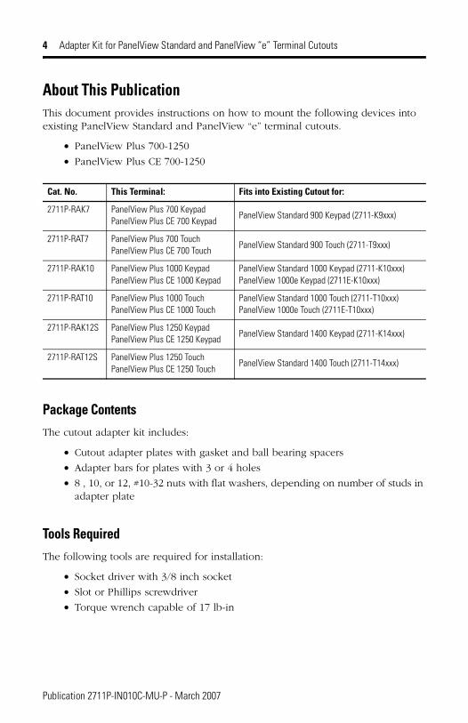
About This PublicationThis document provides instructions on how to mount the following devices into existing PanelView Standard and PanelView “e” terminal cutouts.
• PanelView Plus 700-1250
• PanelView Plus CE 700-1250
Package ContentsThe cutout adapter kit includes:
• Cutout adapter plates with gasket and ball bearing spacers
• Adapter bars for plates with 3 or 4 holes
• 8 , 10, or 12, #10-32 nuts with flat washers, depending on number of studs in adapter plate
Tools RequiredThe following tools are required for installation:
• Socket driver with 3/8 inch socket
• Slot or Phillips screwdriver
• Torque wrench capable of 17 lb-in
Cat. No. This Terminal: Fits into Existing Cutout for:
2711P-RAK7 PanelView Plus 700 Keypad PanelView Plus CE 700 Keypad
PanelView Standard 900 Keypad (2711-K9xxx)
2711P-RAT7 PanelView Plus 700 Touch PanelView Plus CE 700 Touch
PanelView Standard 900 Touch (2711-T9xxx)
2711P-RAK10 PanelView Plus 1000 KeypadPanelView Plus CE 1000 Keypad
PanelView Standard 1000 Keypad (2711-K10xxx)PanelView 1000e Keypad (2711E-K10xxx)
2711P-RAT10 PanelView Plus 1000 TouchPanelView Plus CE 1000 Touch
PanelView Standard 1000 Touch (2711-T10xxx)PanelView 1000e Touch (2711E-T10xxx)
2711P-RAK12S PanelView Plus 1250 KeypadPanelView Plus CE 1250 Keypad
PanelView Standard 1400 Keypad (2711-K14xxx)
2711P-RAT12S PanelView Plus 1250 TouchPanelView Plus CE 1250 Touch
PanelView Standard 1400 Touch (2711-T14xxx)
Publication 2711P-IN010C-MU-P - March 2007
Adapter Kit for PanelView Standard and PanelView “e” Terminal Cutouts 5
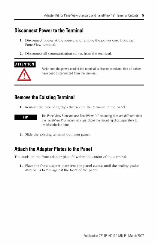
Disconnect Power to the Terminal
1. Disconnect power at the source and remove the power cord from the PanelView terminal.
2. Disconnect all communication cables from the terminal.
Remove the Existing Terminal
1. Remove the mounting clips that secure the terminal in the panel.
2. Slide the existing terminal out from panel.
Attach the Adapter Plates to the PanelThe studs on the front adapter plate fit within the cutout of the terminal.
1. Place the front adapter plate into the panel cutout until the sealing gasket material is firmly against the front of the panel.
ATTENTIONMake sure the power cord of the terminal is disconnected and that all cables have been disconnected from the terminal.
TIP The PanelView Standard and PanelView “e” mounting clips are different than the PanelView Plus mounting clips. Store the mounting clips separately to avoid confusion later.
Publication 2711P-IN010C-MU-P - March 2007
6 Adapter Kit for PanelView Standard and PanelView “e” Terminal Cutouts
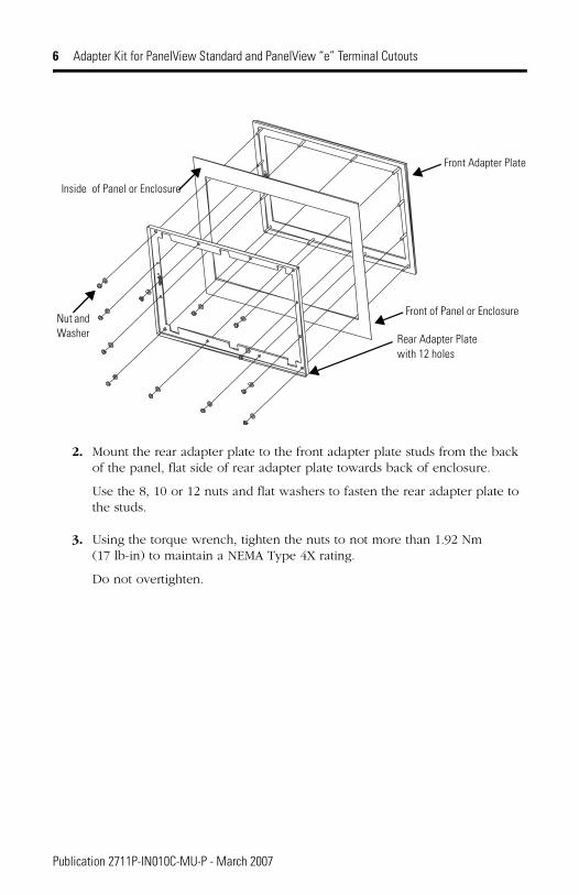
2. Mount the rear adapter plate to the front adapter plate studs from the back of the panel, flat side of rear adapter plate towards back of enclosure.
Use the 8, 10 or 12 nuts and flat washers to fasten the rear adapter plate to the studs.
3. Using the torque wrench, tighten the nuts to not more than 1.92 Nm (17 lb-in) to maintain a NEMA Type 4X rating.
Do not overtighten.
Front Adapter Plate
Rear Adapter Plate with 12 holes
Front of Panel or EnclosureNut and Washer
Inside of Panel or Enclosure
Publication 2711P-IN010C-MU-P - March 2007
Adapter Kit for PanelView Standard and PanelView “e” Terminal Cutouts 7
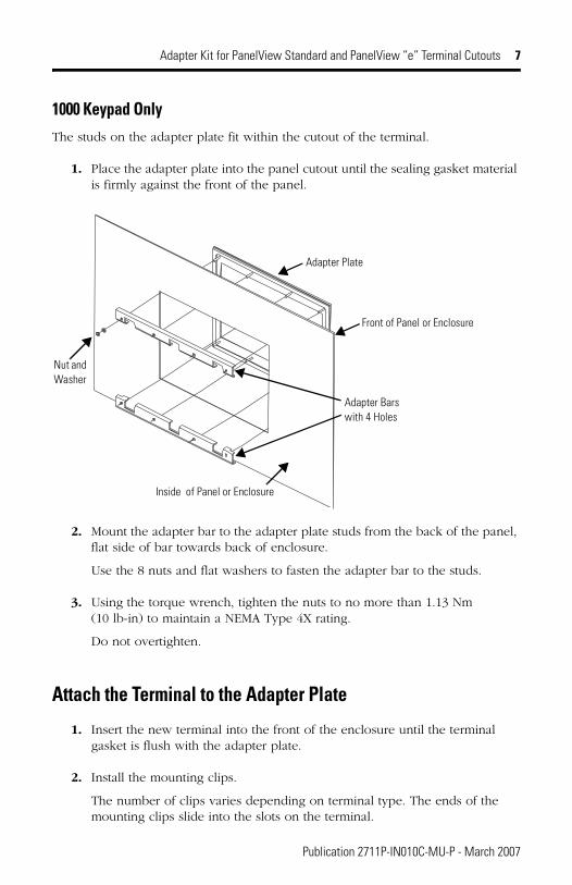
1000 Keypad OnlyThe studs on the adapter plate fit within the cutout of the terminal.
1. Place the adapter plate into the panel cutout until the sealing gasket material is firmly against the front of the panel.
2. Mount the adapter bar to the adapter plate studs from the back of the panel, flat side of bar towards back of enclosure.
Use the 8 nuts and flat washers to fasten the adapter bar to the studs.
3. Using the torque wrench, tighten the nuts to no more than 1.13 Nm (10 lb-in) to maintain a NEMA Type 4X rating.
Do not overtighten.
Attach the Terminal to the Adapter Plate
1. Insert the new terminal into the front of the enclosure until the terminal gasket is flush with the adapter plate.
2. Install the mounting clips.
The number of clips varies depending on terminal type. The ends of the mounting clips slide into the slots on the terminal.
Adapter Plate
Adapter Barswith 4 Holes
Front of Panel or Enclosure
Inside of Panel or Enclosure
Nut and Washer
Publication 2711P-IN010C-MU-P - March 2007
8 Adapter Kit for PanelView Standard and PanelView “e” Terminal Cutouts
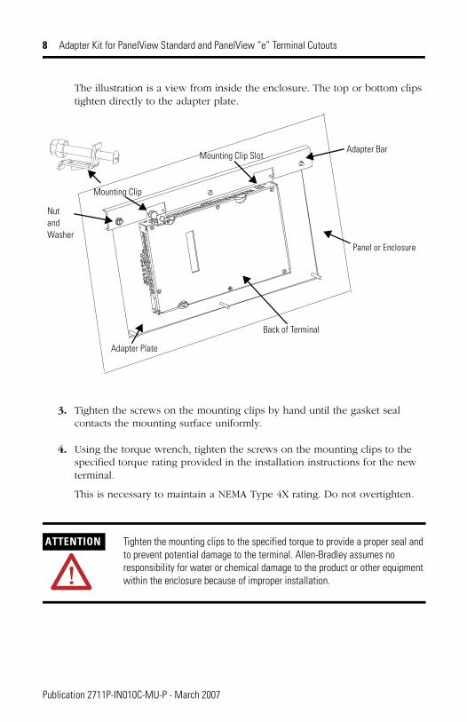
The illustration is a view from inside the enclosure. The top or bottom clips tighten directly to the adapter plate.
3. Tighten the screws on the mounting clips by hand until the gasket seal contacts the mounting surface uniformly.
4. Using the torque wrench, tighten the screws on the mounting clips to the specified torque rating provided in the installation instructions for the new terminal.
This is necessary to maintain a NEMA Type 4X rating. Do not overtighten.
ATTENTION Tighten the mounting clips to the specified torque to provide a proper seal and to prevent potential damage to the terminal. Allen-Bradley assumes no responsibility for water or chemical damage to the product or other equipment within the enclosure because of improper installation.
Adapter Plate
Mounting Clip
Adapter Bar
NutandWasher
Panel or Enclosure
Mounting Clip Slot
Back of Terminal
Publication 2711P-IN010C-MU-P - March 2007

Notice d’installation
Kit d’adaptation pour découpe de terminal PanelView Standard et PanelView « e »
Réf. 2711P-RAK7, 2711P-RAT7, 2711P-RAK10, 2711P-RAT10, 2711P-RAK12S, 2711P-RAT12S
Français
Pour les informations suivantes Voir page
Description 10
Contenu du kit 10
Outils nécessaires 10
Déconnexion du terminal 11
Retrait du terminal existant 11
Fixation des plaques d’adaptation sur le panneau 12
Fixation du terminal à la plaque d’adaptation 13
Publication 2711P-IN010C-MU-P - March 2007
10 Kit d’adaptation pour découpe de terminal PanelView Standard et PanelView « e »
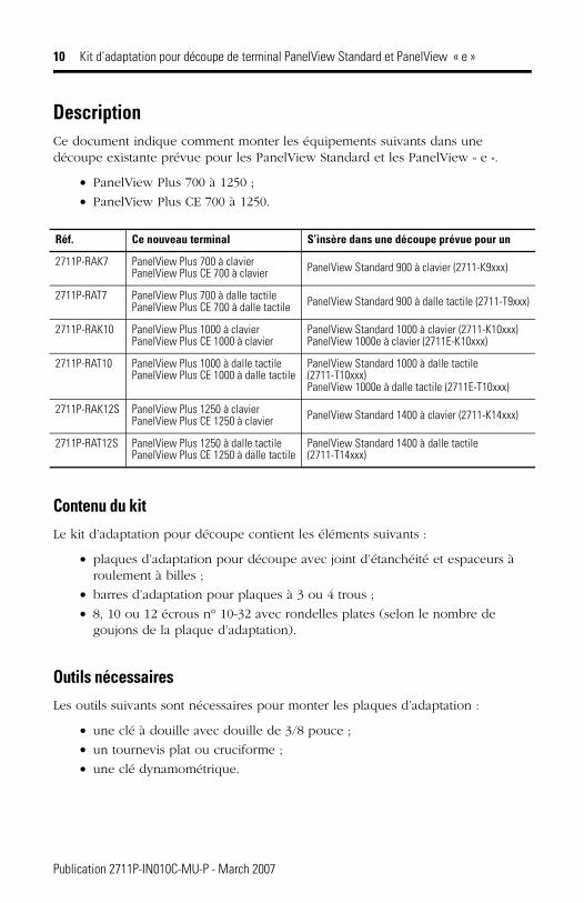
DescriptionCe document indique comment monter les équipements suivants dans une découpe existante prévue pour les PanelView Standard et les PanelView « e ».
• PanelView Plus 700 à 1250 ;
• PanelView Plus CE 700 à 1250.
Contenu du kitLe kit d’adaptation pour découpe contient les éléments suivants :
• plaques d’adaptation pour découpe avec joint d’étanchéité et espaceurs à roulement à billes ;
• barres d’adaptation pour plaques à 3 ou 4 trous ;
• 8, 10 ou 12 écrous n° 10-32 avec rondelles plates (selon le nombre de goujons de la plaque d’adaptation).
Outils nécessairesLes outils suivants sont nécessaires pour monter les plaques d’adaptation :
• une clé à douille avec douille de 3/8 pouce ;
• un tournevis plat ou cruciforme ;
• une clé dynamométrique.
Réf. Ce nouveau terminal S’insère dans une découpe prévue pour un
2711P-RAK7 PanelView Plus 700 à clavierPanelView Plus CE 700 à clavier PanelView Standard 900 à clavier (2711-K9xxx)
2711P-RAT7 PanelView Plus 700 à dalle tactilePanelView Plus CE 700 à dalle tactile PanelView Standard 900 à dalle tactile (2711-T9xxx)
2711P-RAK10 PanelView Plus 1000 à clavierPanelView Plus CE 1000 à clavier
PanelView Standard 1000 à clavier (2711-K10xxx)PanelView 1000e à clavier (2711E-K10xxx)
2711P-RAT10 PanelView Plus 1000 à dalle tactilePanelView Plus CE 1000 à dalle tactile
PanelView Standard 1000 à dalle tactile (2711-T10xxx)PanelView 1000e à dalle tactile (2711E-T10xxx)
2711P-RAK12S PanelView Plus 1250 à clavierPanelView Plus CE 1250 à clavier PanelView Standard 1400 à clavier (2711-K14xxx)
2711P-RAT12S PanelView Plus 1250 à dalle tactilePanelView Plus CE 1250 à dalle tactile
PanelView Standard 1400 à dalle tactile (2711-T14xxx)
Publication 2711P-IN010C-MU-P - March 2007
Kit d’adaptation pour découpe de terminal PanelView Standard et PanelView « e » 11
Déconnexion du terminal
1. Déconnectez l’alimentation à la source et débranchez le cordon d’alimentation du terminal PanelView.
2. Déconnectez tous les câbles de communication du terminal.
Retrait du terminal existant
1. Retirez les colliers de fixation qui maintiennent le terminal sur le panneau.
2. Retirez le terminal du panneau.
ATTENTIONAssurez-vous que le cordon d’alimentation du terminal PanelView est déconnecté et que tous les autres câbles sont déconnectés du terminal.
TIP Les colliers de fixation des PanelView Standard/ PanelView « e » sont différents des colliers des PanelView Plus. Rangez les colliers séparément pour éviter toute erreur par la suite.
Publication 2711P-IN010C-MU-P - March 2007
12 Kit d’adaptation pour découpe de terminal PanelView Standard et PanelView « e »
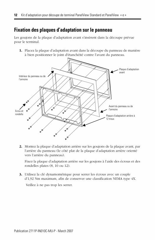
Fixation des plaques d’adaptation sur le panneauLes goujons de la plaque d’adaptation avant s’insèrent dans la découpe prévue pour le terminal.
1. Placez la plaque d’adaptation avant dans la découpe du panneau de manière à bien positionner le joint d'étanchéité contre l’avant du panneau.
2. Montez la plaque d’adaptation arrière sur les goujons de la plaque avant, par l’arrière du panneau (le côté plat de la plaque d’adaptation arrière orienté vers l’arrière du panneau).
Fixez la plaque d’adaptation arrière sur les goujons à l’aide des écrous et des rondelles plates (8, 10 ou 12).
3. Utilisez la clé dynamométrique pour serrer les écrous avec un couple d’1,92 Nm maximum, afin de conserver une classification NEMA type 4X.
Veillez à ne pas trop les serrer.
Plaque d’adaptation avant
Plaque d’adaptation arrière à 12 trous
Avant du panneau ou del’armoireEcrou et
rondelle
Intérieur du panneau ou de l’armoire
Publication 2711P-IN010C-MU-P - March 2007
Kit d’adaptation pour découpe de terminal PanelView Standard et PanelView « e » 13
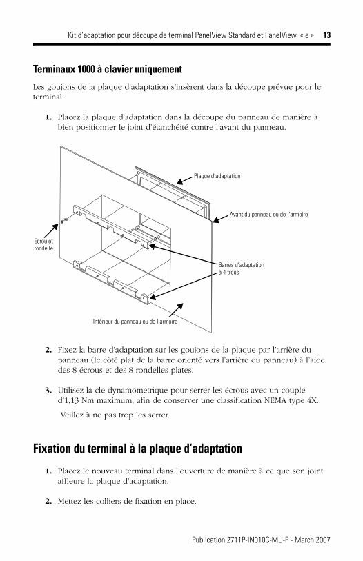
Terminaux 1000 à clavier uniquementLes goujons de la plaque d’adaptation s’insèrent dans la découpe prévue pour le terminal.
1. Placez la plaque d’adaptation dans la découpe du panneau de manière à bien positionner le joint d’étanchéité contre l’avant du panneau.
2. Fixez la barre d’adaptation sur les goujons de la plaque par l’arrière du panneau (le côté plat de la barre orienté vers l’arrière du panneau) à l’aide des 8 écrous et des 8 rondelles plates.
3. Utilisez la clé dynamométrique pour serrer les écrous avec un couple d’1,13 Nm maximum, afin de conserver une classification NEMA type 4X.
Veillez à ne pas trop les serrer.
Fixation du terminal à la plaque d’adaptation
1. Placez le nouveau terminal dans l’ouverture de manière à ce que son joint affleure la plaque d’adaptation.
2. Mettez les colliers de fixation en place.
Plaque d’adaptation
Barres d’adaptationà 4 trous
Avant du panneau ou de l’armoire
Intérieur du panneau ou de l’armoire
Ecrou et rondelle
Publication 2711P-IN010C-MU-P - March 2007
14 Kit d’adaptation pour découpe de terminal PanelView Standard et PanelView « e »
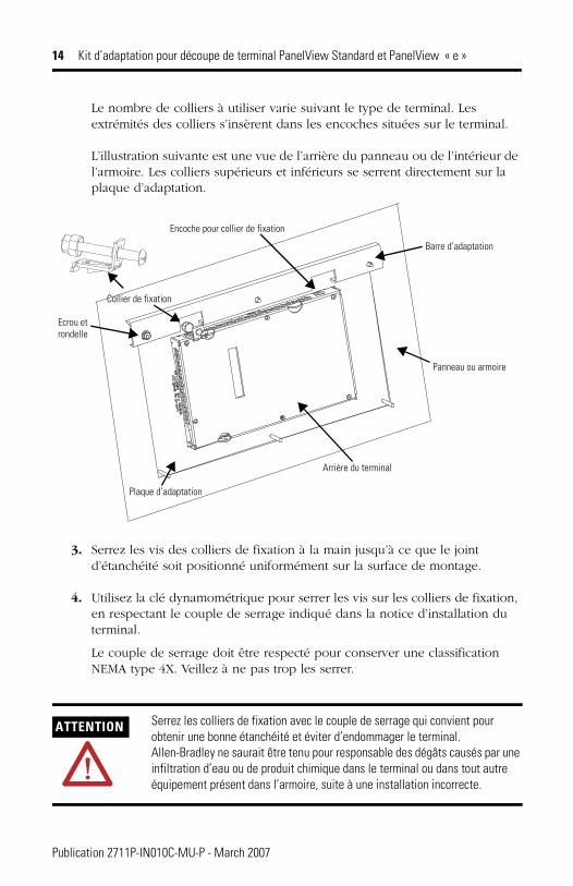
Le nombre de colliers à utiliser varie suivant le type de terminal. Les extrémités des colliers s’insèrent dans les encoches situées sur le terminal.
L’illustration suivante est une vue de l’arrière du panneau ou de l’intérieur de l’armoire. Les colliers supérieurs et inférieurs se serrent directement sur la plaque d’adaptation.
3. Serrez les vis des colliers de fixation à la main jusqu’à ce que le joint d’étanchéité soit positionné uniformément sur la surface de montage.
4. Utilisez la clé dynamométrique pour serrer les vis sur les colliers de fixation, en respectant le couple de serrage indiqué dans la notice d’installation du terminal.
Le couple de serrage doit être respecté pour conserver une classification NEMA type 4X. Veillez à ne pas trop les serrer.
ATTENTION Serrez les colliers de fixation avec le couple de serrage qui convient pour obtenir une bonne étanchéité et éviter d’endommager le terminal. Allen-Bradley ne saurait être tenu pour responsable des dégâts causés par une infiltration d’eau ou de produit chimique dans le terminal ou dans tout autre équipement présent dans l’armoire, suite à une installation incorrecte.
Plaque d’adaptation
Collier de fixation
Barre d’adaptation
Ecrou etrondelle
Panneau ou armoire
Encoche pour collier de fixation
Arrière du terminal
Publication 2711P-IN010C-MU-P - March 2007

Installationsanleitung
Adapter-Kit für Ausschnitte für Terminals des Typs PanelView Standard und PanelView „e“
Bestellnummern 2711P-RAK7, 2711P-RAT7, 2711P-RAK10, 2711P-RAT10, 2711P-RAK12S, 2711P-RAT12S
Deutsch
Thema Seite
Beschreibung 15
Lieferumfang 16
Erforderliche Werkzeuge 16
Abklemmen des Terminals 16
Ausbau eines vorhandenen Terminals 17
Befestigen der Adapterplatten am Schaltschrank 17
Befestigen des Terminals an der Adapterplatte 20
Publication 2711P-IN010C-MU-P - March 2007
16 Adapter-Kit für Ausschnitte für Terminals des Typs PanelView Standard und PanelView „e“
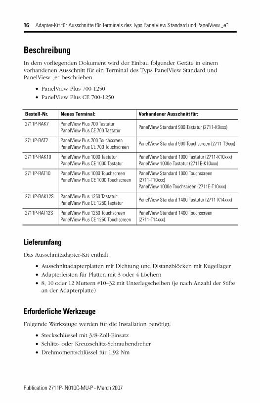
BeschreibungIn dem vorliegenden Dokument wird der Einbau folgender Geräte in einem vorhandenen Ausschnitt für ein Terminal des Typs PanelView Standard und PanelView „e“ beschrieben.
• PanelView Plus 700-1250
• PanelView Plus CE 700-1250
LieferumfangDas Ausschnittadapter-Kit enthält:
• Ausschnittadapterplatten mit Dichtung und Distanzblöcken mit Kugellager
• Adapterleisten für Platten mit 3 oder 4 Löchern
• 8, 10 oder 12 Muttern #10–32 mit Unterlegscheiben (je nach Anzahl der Stifte an der Adapterplatte)
Erforderliche Werkzeuge Folgende Werkzeuge werden für die Installation benötigt:
• Steckschlüssel mit 3/8-Zoll-Einsatz
• Schlitz- oder Kreuzschlitz-Schraubendreher
• Drehmomentschlüssel für 1,92 Nm
Bestell-Nr. Neues Terminal: Vorhandener Ausschnitt für:
2711P-RAK7 PanelView Plus 700 Tastatur PanelView Plus CE 700 Tastatur
PanelView Standard 900 Tastatur (2711-K9xxx)
2711P-RAT7 PanelView Plus 700 Touchscreen PanelView Plus CE 700 Touchscreen
PanelView Standard 900 Touchscreen (2711-T9xxx)
2711P-RAK10 PanelView Plus 1000 TastaturPanelView Plus CE 1000 Tastatur
PanelView Standard 1000 Tastatur (2711-K10xxx)PanelView 1000e Tastatur (2711E-K10xxx)
2711P-RAT10 PanelView Plus 1000 TouchscreenPanelView Plus CE 1000 Touchscreen
PanelView Standard 1000 Touchscreen (2711-T10xxx)PanelView 1000e Touchscreen (2711E-T10xxx)
2711P-RAK12S PanelView Plus 1250 TastaturPanelView Plus CE 1250 Tastatur
PanelView Standard 1400 Tastatur (2711-K14xxx)
2711P-RAT12S PanelView Plus 1250 TouchscreenPanelView Plus CE 1250 Touchscreen
PanelView Standard 1400 Touchscreen (2711-T14xxx)
Publication 2711P-IN010C-MU-P - March 2007

Adapter-Kit für Ausschnitte für Terminals des Typs PanelView Standard und PanelView „e“ 17
Abklemmen des Terminals
1. Unterbrechen Sie die Stromversorgung an der Quelle und ziehen Sie das Netzkabel vom PanelView-Terminal ab.
2. Ziehen Sie alle Kommunikationskabel vom Terminal ab.
Ausbau eines vorhandenen Terminals
1. Entfernen Sie die Montageklammern, mit denen das Terminal im Schaltschrank gesichert ist.
2. Ziehen Sie das vorhandene Terminal aus dem Schaltschrank.
ACHTUNGVergewissern Sie sich, dass das Netzkabel sowie alle anderen Kabel vom PanelView-Terminal abgezogen sind.
TIPP Die Montageklammern für Terminals des Typs PanelView Standard/PanelView „e“ unterscheiden sich von den Klammern für Terminals des Typs PanelView Plus. Zur Vermeidung von Verwechslungen sollten die Montageklammern daher separat aufbewahrt werden.
Publication 2711P-IN010C-MU-P - March 2007
18 Adapter-Kit für Ausschnitte für Terminals des Typs PanelView Standard und PanelView „e“
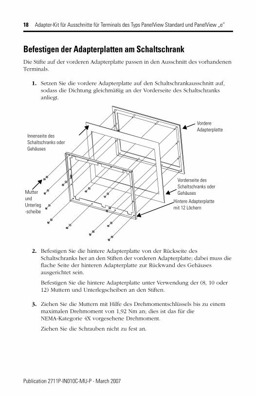
Befestigen der Adapterplatten am SchaltschrankDie Stifte auf der vorderen Adapterplatte passen in den Ausschnitt des vorhandenen Terminals.
1. Setzen Sie die vordere Adapterplatte auf den Schaltschrankausschnitt auf, sodass die Dichtung gleichmäßig an der Vorderseite des Schaltschranks anliegt.
2. Befestigen Sie die hintere Adapterplatte von der Rückseite des Schaltschranks her an den Stiften der vorderen Adapterplatte; dabei muss die flache Seite der hinteren Adapterplatte zur Rückwand des Gehäuses ausgerichtet sein.
Befestigen Sie die hintere Adapterplatte unter Verwendung der (8, 10 oder 12) Muttern und Unterlegscheiben an den Stiften.
3. Ziehen Sie die Muttern mit Hilfe des Drehmomentschlüssels bis zu einem maximalen Drehmoment von 1,92 Nm an; dies ist das für die NEMA-Kategorie 4X vorgesehene Drehmoment.
Ziehen Sie die Schrauben nicht zu fest an.
Vordere Adapterplatte
Hintere Adapterplatte mit 12 Löchern
Vorderseite des Schaltschranks oder GehäusesMutter
und Unterleg-scheibe
Innenseite des Schaltschranks oder Gehäuses
Publication 2711P-IN010C-MU-P - March 2007
Adapter-Kit für Ausschnitte für Terminals des Typs PanelView Standard und PanelView „e“ 19
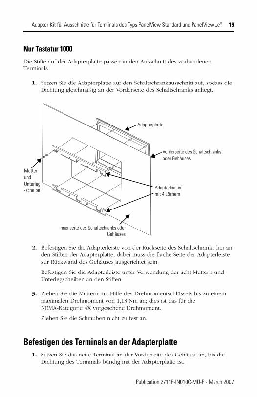
Nur Tastatur 1000Die Stifte auf der Adapterplatte passen in den Ausschnitt des vorhandenen Terminals.
1. Setzen Sie die Adapterplatte auf den Schaltschrankausschnitt auf, sodass die Dichtung gleichmäßig an der Vorderseite des Schaltschranks anliegt.
2. Befestigen Sie die Adapterleiste von der Rückseite des Schaltschranks her an den Stiften der Adapterplatte; dabei muss die flache Seite der Adapterleiste zur Rückwand des Gehäuses ausgerichtet sein.
Befestigen Sie die Adapterleiste unter Verwendung der acht Muttern und Unterlegscheiben an den Stiften.
3. Ziehen Sie die Muttern mit Hilfe des Drehmomentschlüssels bis zu einem maximalen Drehmoment von 1,13 Nm an; dies ist das für die NEMA-Kategorie 4X vorgesehene Drehmoment.
Ziehen Sie die Schrauben nicht zu fest an.
Befestigen des Terminals an der Adapterplatte1. Setzen Sie das neue Terminal an der Vorderseite des Gehäuse an, bis die
Dichtung des Terminals bündig mit der Adapterplatte ist.
Adapterplatte
Adapterleistenmit 4 Löchern
Vorderseite des Schaltschranks oder Gehäuses
Innenseite des Schaltschranks oderGehäuses
Mutter und Unterleg-scheibe
Publication 2711P-IN010C-MU-P - March 2007
20 Adapter-Kit für Ausschnitte für Terminals des Typs PanelView Standard und PanelView „e“
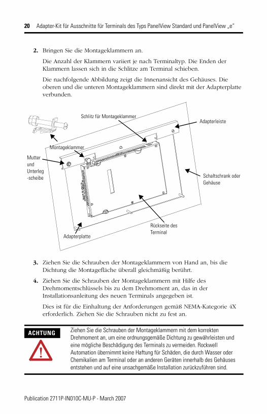
2. Bringen Sie die Montageklammern an.
Die Anzahl der Klammern variiert je nach Terminaltyp. Die Enden der Klammern lassen sich in die Schlitze am Terminal schieben.
Die nachfolgende Abbildung zeigt die Innenansicht des Gehäuses. Die oberen und die unteren Montageklammern sind direkt mit der Adapterplatte verbunden.
3. Ziehen Sie die Schrauben der Montageklammern von Hand an, bis die Dichtung die Montagefläche überall gleichmäßig berührt.
4. Ziehen Sie die Schrauben der Montageklammern mit Hilfe des Drehmomentschlüssels bis zu dem Drehmoment an, das in der Installationsanleitung des neuen Terminals angegeben ist.
Dies ist für die Einhaltung der Anforderungen gemäß NEMA-Kategorie 4X erforderlich. Ziehen Sie die Schrauben nicht zu fest an.
ACHTUNG Ziehen Sie die Schrauben der Montageklammern mit dem korrekten Drehmoment an, um eine ordnungsgemäße Dichtung zu gewährleisten und eine mögliche Beschädigung des Terminals zu vermeiden. Rockwell Automation übernimmt keine Haftung für Schäden, die durch Wasser oder Chemikalien am Terminal oder an anderen Geräten innerhalb des Gehäuses entstehen und auf eine unsachgemäße Installation zurückzuführen sind.
Adapterplatte
Montageklammer
Adapterleiste
Mutter undUnterleg-scheibe Schaltschrank oder
Gehäuse
Schlitz für Montageklammer
Rückseite des Terminal
Publication 2711P-IN010C-MU-P - March 2007
Instrucciones de instalación
Juego adaptador para cortes de terminal PanelView Estándar y PanelView “e”
Números de catálogo 2711P-RAK7, 2711P-RAT7, 2711P-RAK10, 2711P-RAT10, 2711P-RAK12S, 2711P-RAT12S
Español
Para consultar Vea la página
Descripción 21
Contenido del paquete 22
Herramientas requeridas 22
Desconecte el terminal 22
Extraiga el terminal existente 23
Acople las placas adaptadoras al panel 23
Acople el terminal a la placa adaptadora 25
Publication 2711P-IN010BC-MU-P - March 2007
22 Juego adaptador para cortes de terminal PanelView Estándar y PanelView “e”
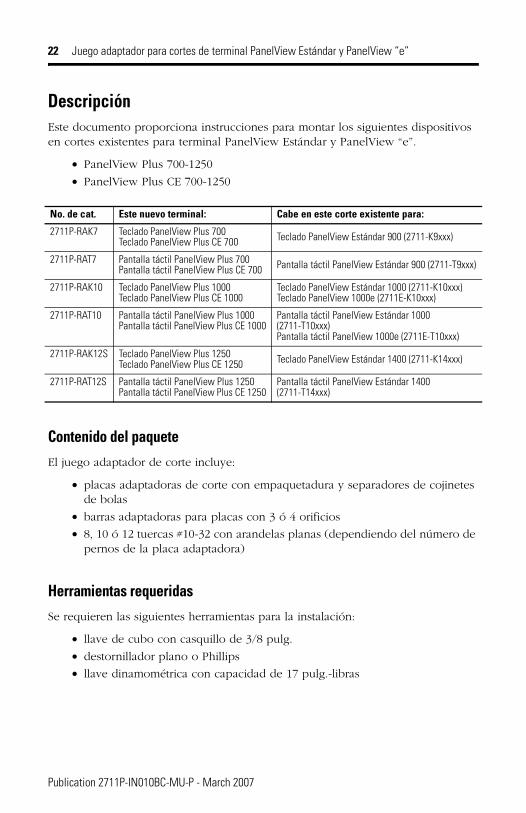
DescripciónEste documento proporciona instrucciones para montar los siguientes dispositivos en cortes existentes para terminal PanelView Estándar y PanelView “e”.
• PanelView Plus 700-1250
• PanelView Plus CE 700-1250
Contenido del paqueteEl juego adaptador de corte incluye:
• placas adaptadoras de corte con empaquetadura y separadores de cojinetes de bolas
• barras adaptadoras para placas con 3 ó 4 orificios
• 8, 10 ó 12 tuercas #10-32 con arandelas planas (dependiendo del número de pernos de la placa adaptadora)
Herramientas requeridasSe requieren las siguientes herramientas para la instalación:
• llave de cubo con casquillo de 3/8 pulg.
• destornillador plano o Phillips
• llave dinamométrica con capacidad de 17 pulg.-libras
No. de cat. Este nuevo terminal: Cabe en este corte existente para:
2711P-RAK7 Teclado PanelView Plus 700 Teclado PanelView Plus CE 700 Teclado PanelView Estándar 900 (2711-K9xxx)
2711P-RAT7 Pantalla táctil PanelView Plus 700 Pantalla táctil PanelView Plus CE 700 Pantalla táctil PanelView Estándar 900 (2711-T9xxx)
2711P-RAK10 Teclado PanelView Plus 1000Teclado PanelView Plus CE 1000
Teclado PanelView Estándar 1000 (2711-K10xxx)Teclado PanelView 1000e (2711E-K10xxx)
2711P-RAT10 Pantalla táctil PanelView Plus 1000Pantalla táctil PanelView Plus CE 1000
Pantalla táctil PanelView Estándar 1000 (2711-T10xxx)Pantalla táctil PanelView 1000e (2711E-T10xxx)
2711P-RAK12S Teclado PanelView Plus 1250Teclado PanelView Plus CE 1250 Teclado PanelView Estándar 1400 (2711-K14xxx)
2711P-RAT12S Pantalla táctil PanelView Plus 1250Pantalla táctil PanelView Plus CE 1250
Pantalla táctil PanelView Estándar 1400 (2711-T14xxx)
Publication 2711P-IN010BC-MU-P - March 2007
Juego adaptador para cortes de terminal PanelView Estándar y PanelView “e” 23
Desconecte el terminal
1. Desconecte la alimentación en la fuente y extraiga el cable de alimentación del terminal PanelView.
2. Desconecte todos los cables de alimentación del terminal.
Extraiga el terminal existente
1. Quite las abrazaderas de montaje que fijan el terminal al panel.
2. Deslice el terminal existente fuera del panel.
ATENCIÓNAsegúrese de que el cable de alimentación del terminal PanelView esté desconectado y que todos los cables hayan sido desconectados del terminal.
TIP Las abrazaderas de montaje del PanelView Estándar/PanelView “e” son diferentes de las abrazaderas de montaje del PanelView Plus. Guarde las abrazaderas de montaje por separado para evitar confusión posteriormente.
Publication 2711P-IN010BC-MU-P - March 2007
24 Juego adaptador para cortes de terminal PanelView Estándar y PanelView “e”
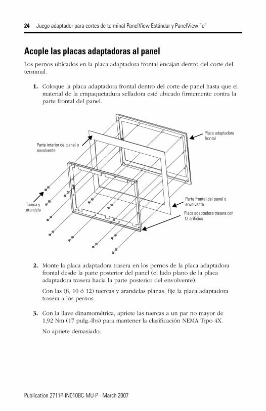
Acople las placas adaptadoras al panelLos pernos ubicados en la placa adaptadora frontal encajan dentro del corte del terminal.
1. Coloque la placa adaptadora frontal dentro del corte de panel hasta que el material de la empaquetadura selladora esté ubicado firmemente contra la parte frontal del panel.
2. Monte la placa adaptadora trasera en los pernos de la placa adaptadora frontal desde la parte posterior del panel (el lado plano de la placa adaptadora trasera hacia la parte posterior del envolvente).
Con las (8, 10 ó 12) tuercas y arandelas planas, fije la placa adaptadora trasera a los pernos.
3. Con la llave dinamométrica, apriete las tuercas a un par no mayor de 1,92 Nm (17 pulg.-lbs) para mantener la clasificación NEMA Tipo 4X.
No apriete demasiado.
Placa adaptadora frontal
Placa adaptadora trasera con 12 orificios
Parte frontal del panel o envolventeTuerca y
arandela
Parte interior del panel o envolvente
Publication 2711P-IN010BC-MU-P - March 2007
Juego adaptador para cortes de terminal PanelView Estándar y PanelView “e” 25
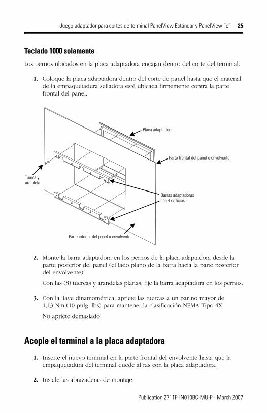
Teclado 1000 solamenteLos pernos ubicados en la placa adaptadora encajan dentro del corte del terminal.
1. Coloque la placa adaptadora dentro del corte de panel hasta que el material de la empaquetadura selladora esté ubicada firmemente contra la parte frontal del panel.
2. Monte la barra adaptadora en los pernos de la placa adaptadora desde la parte posterior del panel (el lado plano de la barra hacia la parte posterior del envolvente).
Con las (8) tuercas y arandelas planas, fije la barra adaptadora en los pernos.
3. Con la llave dinamométrica, apriete las tuercas a un par no mayor de 1,13 Nm (10 pulg.-lbs) para mantener la clasificación NEMA Tipo 4X.
No apriete demasiado.
Acople el terminal a la placa adaptadora
1. Inserte el nuevo terminal en la parte frontal del envolvente hasta que la empaquetadura del terminal quede al ras con la placa adaptadora.
2. Instale las abrazaderas de montaje.
Placa adaptadora
Barras adaptadorascon 4 orificios
Parte frontal del panel o envolvente
Parte interior del panel o envolvente
Tuerca y arandela
Publication 2711P-IN010BC-MU-P - March 2007
26 Juego adaptador para cortes de terminal PanelView Estándar y PanelView “e”
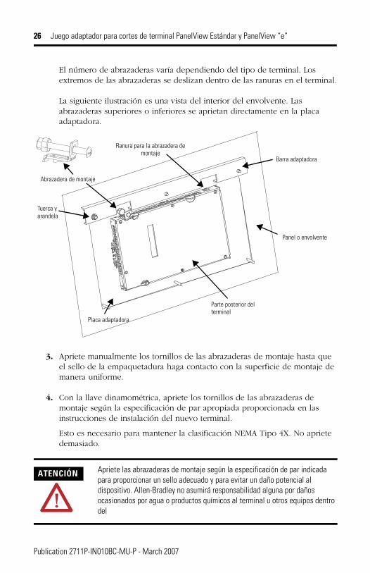
El número de abrazaderas varía dependiendo del tipo de terminal. Los extremos de las abrazaderas se deslizan dentro de las ranuras en el terminal.
La siguiente ilustración es una vista del interior del envolvente. Las abrazaderas superiores o inferiores se aprietan directamente en la placa adaptadora.
3. Apriete manualmente los tornillos de las abrazaderas de montaje hasta que el sello de la empaquetadura haga contacto con la superficie de montaje de manera uniforme.
4. Con la llave dinamométrica, apriete los tornillos de las abrazaderas de montaje según la especificación de par apropiada proporcionada en las instrucciones de instalación del nuevo terminal.
Esto es necesario para mantener la clasificación NEMA Tipo 4X. No apriete demasiado.
ATENCIÓN Apriete las abrazaderas de montaje según la especificación de par indicada para proporcionar un sello adecuado y para evitar un daño potencial al dispositivo. Allen-Bradley no asumirá responsabilidad alguna por daños ocasionados por agua o productos químicos al terminal u otros equipos dentro del
Placa adaptadora
Abrazadera de montaje
Barra adaptadora
Tuerca yarandela
Panel o envolvente
Ranura para la abrazadera de montaje
Parte posterior del terminal
Publication 2711P-IN010BC-MU-P - March 2007

Istruzioni per l’installazione
Kit adattatore per finestrature dei terminali PanelView standard e PanelView “e”
Numero di catalogo 2711P-RAK7, 2711P-RAT7, 2711P-RAK10, 2711P-RAT10, 2711P-RAK12S, 2711P-RAT12S
Italiano
Per: Vedere pagina
Descrizione 27
Contenuto dell'imballaggio 28
Attrezzi necessari 28
Scollegare il terminale 28
Rimuovere il terminale esistente 29
Fissare le piastre adattatrici al pannello 29
Fissare il terminale alla cornice adattatrice 32
Publication 2711P-IN010C-MU-P - March 2007
28 Kit adattatore per finestrature dei terminali PanelView standard e PanelView “e”
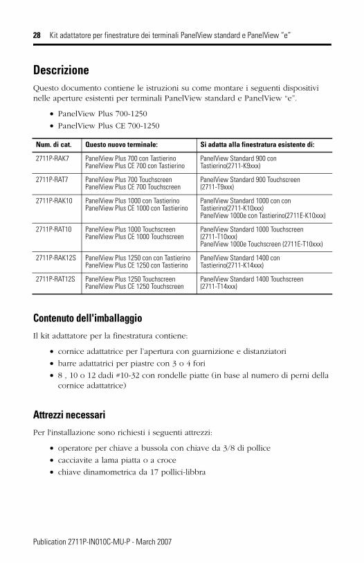
DescrizioneQuesto documento contiene le istruzioni su come montare i seguenti dispositivi nelle aperture esistenti per terminali PanelView standard e PanelView “e”.
• PanelView Plus 700-1250
• PanelView Plus CE 700-1250
Contenuto dell'imballaggioIl kit adattatore per la finestratura contiene:
• cornice adattatrice per l’apertura con guarnizione e distanziatori
• barre adattatrici per piastre con 3 o 4 fori
• 8 , 10 o 12 dadi #10-32 con rondelle piatte (in base al numero di perni della cornice adattatrice)
Attrezzi necessariPer l'installazione sono richiesti i seguenti attrezzi:
• operatore per chiave a bussola con chiave da 3/8 di pollice
• cacciavite a lama piatta o a croce
• chiave dinamometrica da 17 pollici-libbra
Num. di cat. Questo nuovo terminale: Si adatta alla finestratura esistente di:
2711P-RAK7 PanelView Plus 700 con TastierinoPanelView Plus CE 700 con Tastierino
PanelView Standard 900 con Tastierino(2711-K9xxx)
2711P-RAT7 PanelView Plus 700 TouchscreenPanelView Plus CE 700 Touchscreen
PanelView Standard 900 Touchscreen (2711-T9xxx)
2711P-RAK10 PanelView Plus 1000 con TastierinoPanelView Plus CE 1000 con Tastierino
PanelView Standard 1000 con con Tastierino(2711-K10xxx)PanelView 1000e con Tastierino(2711E-K10xxx)
2711P-RAT10 PanelView Plus 1000 TouchscreenPanelView Plus CE 1000 Touchscreen
PanelView Standard 1000 Touchscreen (2711-T10xxx)PanelView 1000e Touchscreen (2711E-T10xxx)
2711P-RAK12S PanelView Plus 1250 con con TastierinoPanelView Plus CE 1250 con Tastierino
PanelView Standard 1400 con Tastierino(2711-K14xxx)
2711P-RAT12S PanelView Plus 1250 TouchscreenPanelView Plus CE 1250 Touchscreen
PanelView Standard 1400 Touchscreen (2711-T14xxx)
Publication 2711P-IN010C-MU-P - March 2007
Kit adattatore per finestrature dei terminali PanelView standard e PanelView “e” 29
Scollegare il terminale
1. Scollegare l'alimentazione e rimuovere il cavo di alimentazione dal terminale PanelView.
2. Scollegare tutti i cavi di comunicazione dal terminale.
Rimuovere il terminale esistente
1. Rimuovere le clip di montaggio che fissare il terminale al pannello.
2. Estrarre il terminale esistente dal pannello.
Fissare le piastre adattatrici al pannelloI perni posti sulla cornice adattatrice anteriore si inseriscono all'interno dell’apertura del terminale.
1. Inserire la cornice adattatrice anteriore nell’apertura del pannello fino a quando la guarnizione di tenuta non tocca il pannello.
AVVERTENZAAssicurarsi che il cavo di alimentazione del terminale PanelView sia scollegato e che tutti i cavi del terminale siano stati scollegati.
TIP Le clip di montaggio del terminal PanelView Standard/PanelView “e” sono diverse da quelle del terminale PanelView Plus. Conservare separatamente le clip di montaggio per evitare confusione successivamente.
Publication 2711P-IN010C-MU-P - March 2007
30 Kit adattatore per finestrature dei terminali PanelView standard e PanelView “e”
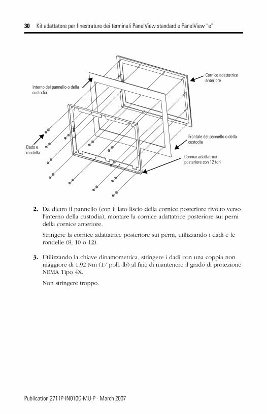
2. Da dietro il pannello (con il lato liscio della cornice posteriore rivolto verso l'interno della custodia), montare la cornice adattatrice posteriore sui perni della cornice anteriore.
Stringere la cornice adattatrice posteriore sui perni, utilizzando i dadi e le rondelle (8, 10 o 12).
3. Utilizzando la chiave dinamometrica, stringere i dadi con una coppia non maggiore di 1.92 Nm (17 poll.-lb) al fine di mantenere il grado di protezione NEMA Tipo 4X.
Non stringere troppo.
Cornice adattatrice anteriore
Cornice adattatrice posteriore con 12 fori
Frontale del pannello o della custodia
Dado e rondella
Interno del pannello o della custodia
Publication 2711P-IN010C-MU-P - March 2007
Kit adattatore per finestrature dei terminali PanelView standard e PanelView “e” 31
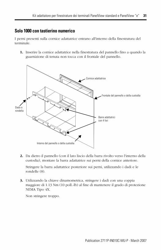
Solo 1000 con tastierino numericoI perni presenti sulla cornice adattatrice entrano all'interno della finestratura del terminale.
1. Inserire la cornice adattatrice nella finestratura del pannello fino a quando la guarnizione di tenuta non tocca con il frontale del pannello.
2. Da dietro il pannello (con il lato liscio della barra rivolto verso l'interno della custodia), montare la barra adattatrice sui perni della cornice anteriore.
Stringere la barra adattatrice posteriore sui perni, utilizzando i dadi e le rondelle (8).
3. Utilizzando la chiave dinamometrica, stringere i dadi con una coppia maggiore di 1.13 Nm (10 poll.-lb) al fine di mantenere il grado di protezione NEMA Tipo 4X.
Non stringere troppo.
Cornice adattatrice
Barre adattatricicon 4 fori
Frontale del pannello o della custodia
Interno del pannello o della custodia
Dado e rondella
Publication 2711P-IN010C-MU-P - March 2007
32 Kit adattatore per finestrature dei terminali PanelView standard e PanelView “e”
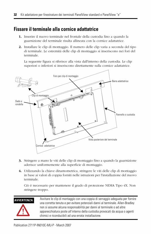
Fissare il terminale alla cornice adattatrice1. Inserire il nuovo terminale nel frontale della custodia fino a quando la
guarnizione del terminale risulta allineata con la cornice adattatrice.
2. Installare le clip di montaggio. Il numero delle clip varia a seconda del tipo di terminale. Le estremità delle clip di montaggio si inseriscono nei fori del terminale.
La seguente figura si riferisce alla vista dall'interno della custodia. Le clip superiori o inferiori si inseriscono direttamente sulla cornice adattatrice.
3. Stringere a mano le viti delle clip di montaggio fino a quando la guarnizione aderisce uniformemente alla superficie di montaggio.
4. Utilizzando la chiave dinamometrica, stringere le viti delle clip di montaggio in base ai valori di coppia forniti nelle istruzioni per l'installazione del nuovo terminale.
Ciò è necessario per mantenere il grado di protezione NEMA Tipo 4X. Non stringere troppo.
AVVERTENZA Avvitare le clip di montaggio con una coppia di serraggio adeguata per fornire una corretta tenuta e per evitare potenziali danni al terminale. Allen-Bradley non si assume alcuna responsabilità per danni al terminale o ad altre apparecchiatura poste all'interno della custodia provocati da acqua o agenti chimici e riconducibili ad una errata installazione.
Cornice adattatrice
Clip di montaggio
Barra adattatrice
Dado erondella
Pannello o custodia
Foro per clip di montaggio
Vista posteriore del terminale
Publication 2711P-IN010C-MU-P - March 2007

Instruções de Instalação
Kit de Adaptador para Cortes dos Terminais PanelView Standard e PanelView “e”
Código de Catálogo 2711P-RAK7, 2711P-RAT7, 2711P-RAK10, 2711P-RAT10, 2711P-RAK12S, 2711P-RAT12S
Português
Para Consulte a página
Descrição 33
Conteúdo do Pacote 34
Ferramentas Necessárias 34
Desconexão do Terminal 34
Remoção do Terminal Existente 35
Ligação das Placas do Adaptador ao Painel 35
Fixação do Terminal à Placa do Adaptador 37
Publication 2711P-IN010C-MU-P - March 2007
34 Kit de Adaptador para Cortes dos Terminais PanelView Standard e PanelView “e”
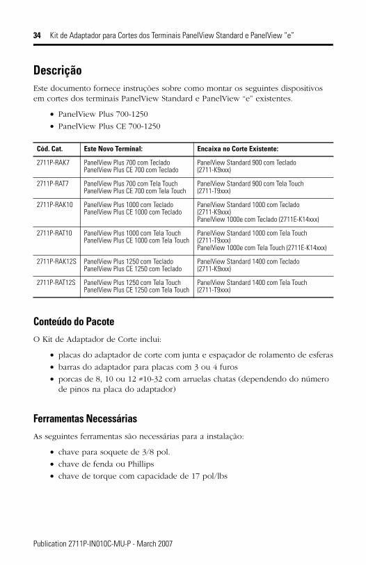
DescriçãoEste documento fornece instruções sobre como montar os seguintes dispositivos em cortes dos terminais PanelView Standard e PanelView “e” existentes.
• PanelView Plus 700-1250
• PanelView Plus CE 700-1250
Conteúdo do PacoteO Kit de Adaptador de Corte inclui:
• placas do adaptador de corte com junta e espaçador de rolamento de esferas
• barras do adaptador para placas com 3 ou 4 furos
• porcas de 8, 10 ou 12 #10-32 com arruelas chatas (dependendo do número de pinos na placa do adaptador)
Ferramentas NecessáriasAs seguintes ferramentas são necessárias para a instalação:
• chave para soquete de 3/8 pol.
• chave de fenda ou Phillips
• chave de torque com capacidade de 17 pol/lbs
Cód. Cat. Este Novo Terminal: Encaixa no Corte Existente:
2711P-RAK7 PanelView Plus 700 com TecladoPanelView Plus CE 700 com Teclado
PanelView Standard 900 com Teclado (2711-K9xxx)
2711P-RAT7 PanelView Plus 700 com Tela Touch PanelView Plus CE 700 com Tela Touch
PanelView Standard 900 com Tela Touch (2711-T9xxx)
2711P-RAK10 PanelView Plus 1000 com TecladoPanelView Plus CE 1000 com Teclado
PanelView Standard 1000 com Teclado (2711-K9xxx)PanelView 1000e com Teclado (2711E-K14xxx)
2711P-RAT10 PanelView Plus 1000 com Tela TouchPanelView Plus CE 1000 com Tela Touch
PanelView Standard 1000 com Tela Touch (2711-T9xxx)PanelView 1000e com Tela Touch (2711E-K14xxx)
2711P-RAK12S PanelView Plus 1250 com TecladoPanelView Plus CE 1250 com Teclado
PanelView Standard 1400 com Teclado (2711-K9xxx)
2711P-RAT12S PanelView Plus 1250 com Tela TouchPanelView Plus CE 1250 com Tela Touch
PanelView Standard 1400 com Tela Touch (2711-T9xxx)
Publication 2711P-IN010C-MU-P - March 2007
Kit de Adaptador para Cortes dos Terminais PanelView Standard e PanelView “e” 35
Desconexão do Terminal
1. Desconecte a alimentação na fonte e remova o fio de alimentação do terminal PanelView.
2. Desconecte todos os cabos de comunicação do terminal.
Remoção do Terminal Existente
1. Remova os clips de montagem que prendem o terminal no painel.
2. Deslize o terminal existente para fora do painel.
ADVERTÊNCIACertifique-se de que o fio de alimentação do terminal PanelView esteja desconectado e que todos os cabos tenham sido desconectados do terminal.
TIP Os clips de montagem do PanelView Standard/PanelView “e” são diferentes dos clips do PanelView Plus. Armazene os clips de montagem separadamente para evitar confusões futuras.
Publication 2711P-IN010C-MU-P - March 2007
36 Kit de Adaptador para Cortes dos Terminais PanelView Standard e PanelView “e”
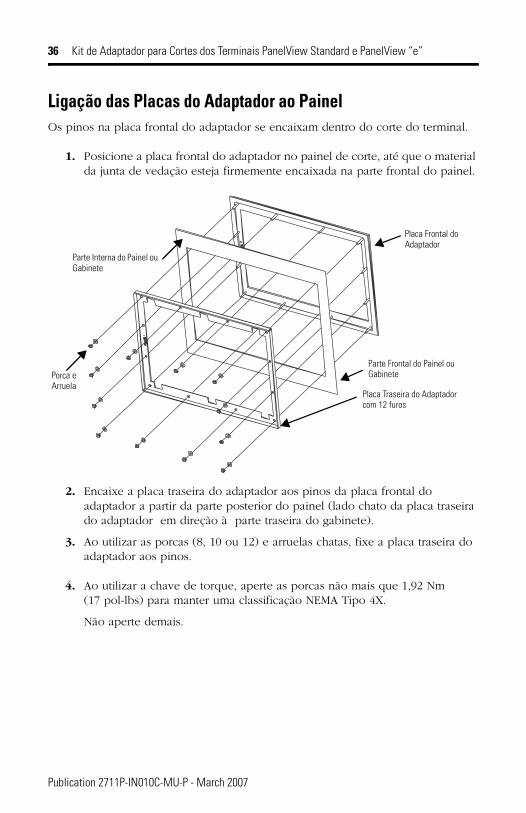
Ligação das Placas do Adaptador ao PainelOs pinos na placa frontal do adaptador se encaixam dentro do corte do terminal.
1. Posicione a placa frontal do adaptador no painel de corte, até que o material da junta de vedação esteja firmemente encaixada na parte frontal do painel.
2. Encaixe a placa traseira do adaptador aos pinos da placa frontal do adaptador a partir da parte posterior do painel (lado chato da placa traseira do adaptador em direção à parte traseira do gabinete).
3. Ao utilizar as porcas (8, 10 ou 12) e arruelas chatas, fixe a placa traseira do adaptador aos pinos.
4. Ao utilizar a chave de torque, aperte as porcas não mais que 1,92 Nm (17 pol-lbs) para manter uma classificação NEMA Tipo 4X.
Não aperte demais.
Placa Frontal do Adaptador
Placa Traseira do Adaptador com 12 furos
Parte Frontal do Painel ou GabinetePorca e
Arruela
Parte Interna do Painel ou Gabinete
Publication 2711P-IN010C-MU-P - March 2007
Kit de Adaptador para Cortes dos Terminais PanelView Standard e PanelView “e” 37
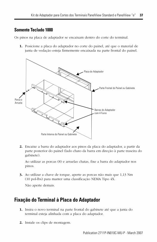
Somente Teclado 1000Os pinos na placa de adaptador se encaixam dentro do corte do terminal.
1. Posicione a placa do adaptador no corte do painel, até que o material de junta de vedação esteja firmemente encaixada na parte frontal do painel.
2. Encaixe a barra do adaptador aos pinos da placa do adaptador, a partir da parte posterior do painel (lado chato da barra em direção à parte traseira do gabinete).
Ao utilizar as porcas (8) e arruelas chatas, fixe a barra do adaptador nos pinos.
3. Ao utilizar a chave de torque, aperte as porcas não mais que 1,13 Nm (10 pol-lbs) para manter uma classificação NEMA Tipo 4X.
Não aperte demais.
Fixação do Terminal à Placa do Adaptador
1. Insira o novo terminal na parte frontal do gabinete até que a junta do terminal esteja alinhada com a placa do adaptador.
2. Instale os clips de montagem.
Placa do Adaptador
Barras do Adaptadorcom 4 Furos
Parte Frontal do Painel ou Gabinete
Parte Interna do Painel ou Gabinete
Porca e Arruela
Publication 2711P-IN010C-MU-P - March 2007
38 Kit de Adaptador para Cortes dos Terminais PanelView Standard e PanelView “e”
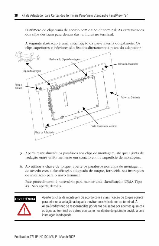
O número de clips varia de acordo com o tipo de terminal. As extremidades dos clips deslizam para dentro das ranhuras no terminal.
A seguinte ilustração é uma visualização da parte interna do gabinete. Os clips superiores e inferiores são fixados diretamente à placa do adaptador.
3. Aperte manualmente os parafusos nos clips de montagem, até que a junta de vedação entre uniformemente em contato com a superfície de montagem.
4. Ao utilizar a chave de torque, aperte os parafusos nos clips de montagem, de acordo com a classificação adequada de torque, fornecida nas instruções de instalação para o novo terminal.
Este procedimento é necessário para manter uma classificação NEMA Tipo 4X. Não aperte demais.
ADVERTÊNCIA Aperte os clips de montagem de acordo com a classificação de torque correta para criar uma vedação adequada e evitar possíveis danos ao terminal. A Allen-Bradley não se responsabiliza por danos causados por agentes químicos ou água ao terminal ou outros equipamentos dentro do gabinete devido a uma instalação inadequada.
Placa do Adaptador
Clip de Montagem
Barra do Adaptador
Porca eArruela
Painel ou Gabinete
Ranhura do Clip de Montagem
Parte Traseira do Terminal
Publication 2711P-IN010C-MU-P - March 2007


Rockwell Automation Support
Publication 2711P-IN010C-MU-P - March 2007 PN 41061-305-01(3)Supersedes Publication 2711P-IN010B-MU-P - April 2003 Copyright © 2007 Rockwell Automation, Inc. All rights reserved. Printed in the U.S.A.
Rockwell Automation provides technical information on the Web to assist you in using its products. At http://support.rockwellautomation.com, you can find technical manuals, a knowledge base of FAQs, technical and application notes, sample code and links to software service packs, and a MySupport feature that you can customize to make the best use of these tools.
For an additional level of technical phone support for installation, configuration, and troubleshooting, we offer TechConnect Support programs. For more information, contact your local distributor or Rockwell Automation representative, or visit http://support.rockwellautomation.com.
Installation AssistanceIf you experience a problem with a hardware module within the first 24 hours of installation, please review the information that's contained in this manual. You can also contact a special Customer Support number for initial help in getting your module up and running.
New Product Satisfaction ReturnRockwell tests all of its products to ensure that they are fully operational when shipped from the manufacturing facility. However, if your product is not functioning, it may need to be returned.
Allen-Bradley, PanelView, TechConnect, and Rockwell Automation are trademarks of Rockwell Automation, Inc.
Trademarks not belonging to Rockwell Inc. are property of their respective companies.
United States 1.440.646.3223Monday – Friday, 8am – 5pm EST
Outside United States
Please contact your local Rockwell Automation representative for any technical support issues.
United States Contact your distributor. You must provide a Customer Support case number (see phone number above to obtain one) to your distributor in order to complete the return process.
Outside United States
Please contact your local Rockwell Automation representative for return procedure.