Embed Size (px)
Citation preview
This Operator’s Manual
MUST BE READ AND UNDERSTOOD
prior to operating your
MEC Aerial Work Platform
OPERATOR’S MANUAL
Part # 90724Issued May 2004
2633ES

Page i2633ES Operator’s Manual May 2004
TABLE OF CONTENTSIntroduction ........................................................................................................ iiiMachine Specifications
2633ES .................................................................................................... iv
Section 1: SafetySafety Symbols ........................................................................................ 1-2Safety Rules And Precautions ................................................................. 1-3Fall Protection Notice ............................................................................... 1-5Safety And Control Decal Locations ........................................................ 1-6Safety Related Decals ............................................................................. 1-8
Section 2: OperationUnloading Procedures ............................................................................. 2-2Primary Machine Components ................................................................. 2-3Operator Controls .................................................................................... 2-4
Base Controls ................................................................................. 2-4Platform Controls ............................................................................ 2-6
Prestart Inspection ................................................................................... 2-8Machine Start Up ............................................................................ 2-8Base Control Operation And Checks .............................................. 2-9Platform Control Operation And Checks......................................... 2-10
Operation ................................................................................................. 2-11Driving And Steering ....................................................................... 2-11Braking ........................................................................................... 2-12Elevating The Platform ................................................................... 2-12Lowering The Platform ................................................................... 2-12Extending The Roll-Out Extension Deck ........................................ 2-13
Charging the Batteries ............................................................................. 2-13Shut Down Procedure .............................................................................. 2-14Moving The Machine ................................................................................ 2-14Emergency Systems And Procedures ..................................................... 2-16
Emergency Lowering ...................................................................... 2-17
Page iiMay 2004 2633ES Operator’s Manual
Section 3: MaintenanceGeneral Maintenance Tips ....................................................................... 3-2Prestart Inspection ................................................................................... 3-4Frequent Inspection ................................................................................. 3-6Annual Inspection .................................................................................... 3-7Troubleshooting ....................................................................................... 3-9
What To Check If Functions Will Not Operate ................................ 3-9Lubrication Diagram ................................................................................. 3-10Lubrication Chart ...................................................................................... 3-11
Warranty
Page iii2633ES Operator’s Manual May 2004
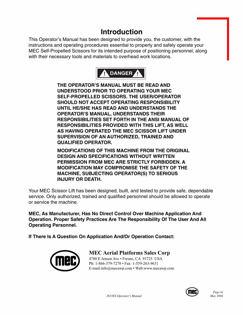
IntroductionThis Operator’s Manual has been designed to provide you, the customer, with theinstructions and operating procedures essential to properly and safely operate yourMEC Self-Propelled Scissors for its intended purpose of positioning personnel, alongwith their necessary tools and materials to overhead work locations.
THE OPERATOR’S MANUAL MUST BE READ ANDUNDERSTOOD PRIOR TO OPERATING YOUR MECSELF-PROPELLED SCISSORS. THE USER/OPERATORSHOULD NOT ACCEPT OPERATING RESPONSIBILITYUNTIL HE/SHE HAS READ AND UNDERSTANDS THEOPERATOR’S MANUAL, UNDERSTANDS THEIRRESPONSIBILITIES SET FORTH IN THE ANSI MANUAL OFRESPONSIBILITIES PROVIDED WITH THIS LIFT, AS WELLAS HAVING OPERATED THE MEC SCISSOR LIFT UNDERSUPERVISION OF AN AUTHORIZED, TRAINED ANDQUALIFIED OPERATOR.
MODIFICATIONS OF THIS MACHINE FROM THE ORIGINALDESIGN AND SPECIFICATIONS WITHOUT WRITTENPERMISSION FROM MEC ARE STRICTLY FORBIDDEN. AMODIFICATION MAY COMPROMISE THE SAFETY OF THEMACHINE, SUBJECTING OPERATOR(S) TO SERIOUSINJURY OR DEATH.
Your MEC Scissor Lift has been designed, built, and tested to provide safe, dependableservice. Only authorized, trained and qualified personnel should be allowed to operateor service the machine.
MEC, As Manufacturer, Has No Direct Control Over Machine Application AndOperation. Proper Safety Practices Are The Responsibility Of The User And AllOperating Personnel.
If There Is A Question On Application And/Or Operation Contact:
MEC Aerial Platforms Sales Corp4780 E Jensen Ave • Fresno, CA 93725 USAPh: 1-866-379-7278 • Fax: 1-559-263-9631E-mail:[email protected] • Web:www.mecawp.com
Page ivMay 2004 2633ES Operator’s Manual
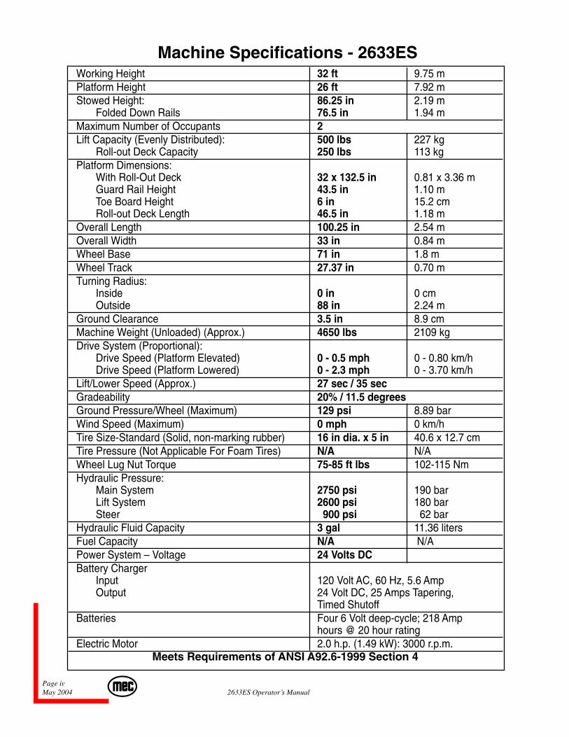
Machine Specifications - 2633ESWorking Height 32 ft 9.75 mPlatform Height 26 ft 7.92 mStowed Height: 86.25 in 2.19 m
Folded Down Rails 76.5 in 1.94 mMaximum Number of Occupants 2Lift Capacity (Evenly Distributed): 500 lbs 227 kg
Roll-out Deck Capacity 250 lbs 113 kgPlatform Dimensions:
With Roll-Out Deck 32 x 132.5 in 0.81 x 3.36 mGuard Rail Height 43.5 in 1.10 mToe Board Height 6 in 15.2 cmRoll-out Deck Length 46.5 in 1.18 m
Overall Length 100.25 in 2.54 mOverall Width 33 in 0.84 mWheel Base 71 in 1.8 mWheel Track 27.37 in 0.70 mTurning Radius:
Inside 0 in 0 cmOutside 88 in 2.24 m
Ground Clearance 3.5 in 8.9 cmMachine Weight (Unloaded) (Approx.) 4650 lbs 2109 kgDrive System (Proportional):
Drive Speed (Platform Elevated) 0 - 0.5 mph 0 - 0.80 km/hDrive Speed (Platform Lowered) 0 - 2.3 mph 0 - 3.70 km/h
Lift/Lower Speed (Approx.) 27 sec / 35 secGradeability 20% / 11.5 degreesGround Pressure/Wheel (Maximum) 129 psi 8.89 barWind Speed (Maximum) 0 mph 0 km/hTire Size-Standard (Solid, non-marking rubber) 16 in dia. x 5 in 40.6 x 12.7 cmTire Pressure (Not Applicable For Foam Tires) N/A N/AWheel Lug Nut Torque 75-85 ft lbs 102-115 NmHydraulic Pressure:
Main System 2750 psi 190 barLift System 2600 psi 180 barSteer 900 psi 62 bar
Hydraulic Fluid Capacity 3 gal 11.36 litersFuel Capacity N/A N/APower System – Voltage 24 Volts DCBattery Charger
Input 120 Volt AC, 60 Hz, 5.6 AmpOutput 24 Volt DC, 25 Amps Tapering,
Timed ShutoffBatteries Four 6 Volt deep-cycle; 218 Amp
hours @ 20 hour ratingElectric Motor 2.0 h.p. (1.49 kW): 3000 r.p.m.
Meets Requirements of ANSI A92.6-1999 Section 4

Page 1-12633ES Operator’s Manual May 2004
SECTION 1:SAFETY
Page 1-2May 2004 2633ES Operator’s Manual
SAFETY SYMBOLSThis section of the manual contains important information of the safe use of your MECScissors. Failure to read, understand, and follow all safety rules, warnings, and instructionswill unnecessarily expose you and others to dangerous situations. For your safety and thesafety of those around you, you must operate your machine as instructed in this manual.
You, the operator, are the single most important factor for safety when using any piece ofequipment. Learn to operate your machine in a safe manner.
To help you recognize important safety information, we have identified warnings and in-structions that directly impact on safety with the following signals:
“DANGER” INDICATES AN IMMINENTLY HAZARDOUSSITUATION WHICH, IF NOT AVOIDED, WILL RESULT IN DEATHOR SERIOUS INJURY. THIS SIGNAL WORD IS LIMITED TO THEMOST EXTREME SITUATIONS.
“WARNING” INDICATES A POTENTIALLY HAZARDOUSSITUATION WHICH, IF NOT AVOIDED, COULD RESULT INDEATH OR SERIOUS INJURY.
“CAUTION” indicates a potentially hazardous situation which, if notavoided, may result in minor or moderate injury. It may also be usedto alert against unsafe practices. “CAUTION” is used for property-damage only accidents.
Page 1-32633ES Operator’s Manual May 2004
Safety Rules And Precautions♦ MEC designs self-propelled scissor lifts to be safe and reliable. They are in-
tended to position personnel, along with their necessary tools and materials tooverhead work locations.
♦ The owner/user/operator of the machine should not accept responsibility for theoperation of the machine, unless properly trained.
♦ ANSI A92.6 and other applicable standards identify requirements of all partieswho may be involved with self-propelled elevating work platforms. The A92.6Manual of Responsibilities is considered a part of this machine and can be foundin the manual compartment, located at the platform control station.
♦ To insure safe use of machine, inspections specified in Section 6.7 ofANSI A92.6-1999 must be performed at designated intervals as prescribed byANSI A92.6-1999.
♦♦♦♦♦ ELECTROCUTION HAZARD!!! THIS MACHINE IS NOT INSULATED!!
♦ Maintain safe clearance from electrically charged conductors (power lines) andapparatus. You must allow for machine sway (side to side movement) whenelevated and electrical line movement. This machine does not provide protectionfrom contact with, or proximity to, an electrically charged conductor.
♦ You must maintain a CLEARANCE OF AT LEAST 10 FEET (3.05 m) betweenany part of the machine, or its load, and any electrical line or apparatus carryingover 300 volts up to 50,000 volts. One foot (30.5 cm) additional clearance isrequired for every additional 30,000 volts.
♦ DEATH OR SERIOUS INJURY will result from contact with or inadequate clear-ance from any electrically charged conductor.
♦ Only authorized, trained and qualified personnel should operate the scissor lift.
♦ NEVER fasten fall protection lanyard to an adjacent structure while on the plat-form.
♦ Make sure that the platform entry is properly closed and secure before operatingmachine from the platform.
♦ NEVER exceed platform rated capacity. Review the section titled “MachineSpecifications” (earlier in this manual) regarding model capacities and dimen-sions.
Page 1-4May 2004 2633ES Operator’s Manual
♦ Before operating the machine, read and understand all safety and control informa-tion found on the machine and in this manual.
♦ When operating the machine follow all safety and control information found on themachine and in this manual.
♦ Evenly distribute loads placed on the platform.
♦ NEVER use scaffolding, ladders or similar items to extend your reach while on theplatform.
♦ NEVER climb down the beam assembly while the platform is raised.
♦ The “Moving the Machine” section (described later in this manual) requires that thebrake be released. After performing this procedure, there is no means to stop themachine’s travel. MEC recommends using this procedure only in cases of emer-gency, and only for a short distance. Be on guard against machine runaway onsloping surfaces. Movement speed shall not exceed 5 MPH (8.0 kph).
♦ NEVER attempt to open any hydraulic line or component without first relieving allsystem pressure.
♦ NEVER alter, modify, or disable any safety devices or interlocks.
♦ NEVER recharge the battery near sparks or open flames. Lead-acid batteries gener-ate EXPLOSIVE HYDROGEN GAS. Always wear safety glasses.
♦ NEVER use the machine outdoors during electrical storms or in high wind situations.
♦ Only raise the platform when the machine is on a firm, level surface.
♦ SECURE all tools and other loose items to prevent injury to persons working on orbelow the platform.
♦ Precautions should be taken to prevent unauthorized personnel from operating theplatform with the ground controls while the platform is in use.
♦ Before disengaging or disconnecting hydraulic motors with brake assembly from atowing vehicle, ensure that the machine cannot roll.
♦ Complete the “Operational Checklist” at designated intervals.
Page 1-52633ES Operator’s Manual May 2004
♦ Use of scissor lift as a crane to lift oversized or hanging loads is prohibited.
♦ Always check route and areas are clear before driving, lifting or lowering.
♦ It is recommended to avoid sudden braking or steering. Go slowly and leavemore maneuvering room during cold weather operation.
Fall Protection NoticeThe Guardrail System around the perimeter of the platform is the fall protection sys-tem for self-propelled elevating work platforms per the American National StandardsInstitute ANSI/SIA A92.6 Standard. It is prohibited to use an Aerial Work Platformmanufactured by MEC with any portion, or all, of the guardrails removed.
Lanyard anchorage points on this type of equipment are not required to conform to theapplicable ANSI/SIA Standard.
THE IMPROPER USE OF FALL ARREST SYSTEMS MAYCAUSE MACHINE TO TIP RESULTING IN SERIOUS INJURYOR DEATH.
However, if anchorage points for lanyard attachments are required by site authorities orother regulations, the anchorage points on all equipment manufactured by MEC arerecommended to be used for work positioning restraints of personnel only. Lanyardlengths are to be determined by operator/owner to restrict the operator to the confineswithin the Guardrail System.
Page 1-6May 2004 2633ES Operator’s Manual
6
1
2
3
4
19
23
24
20
18
28
227
26
21
19
27 15
29
3225
5 7 8 9 10 11
12 13
2
14
33
33
30
16
31INSIDE
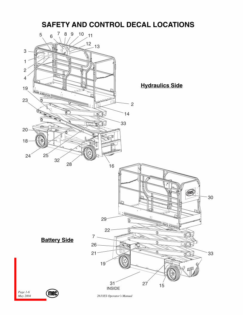
SAFETY AND CONTROL DECAL LOCATIONS
Hydraulics Side
Battery Side
Page 1-72633ES Operator’s Manual May 2004
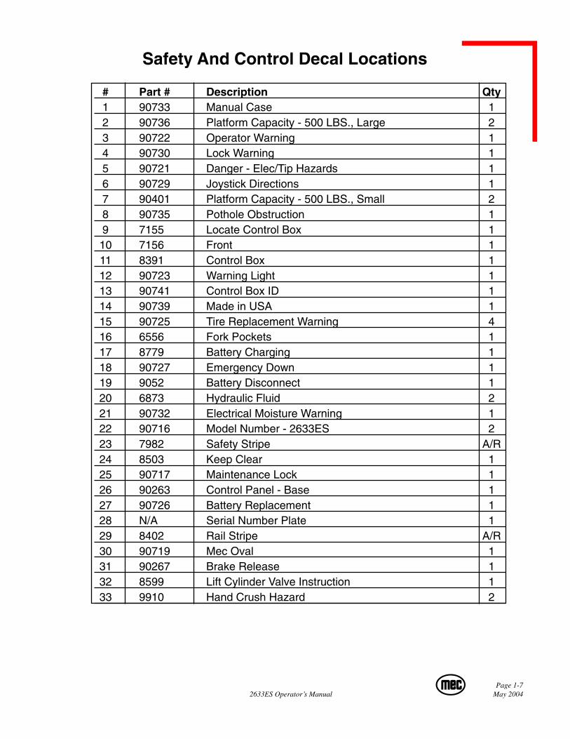
Safety And Control Decal Locations
# Part # Description Qty1 90733 Manual Case 12 90736 Platform Capacity - 500 LBS., Large 23 90722 Operator Warning 14 90730 Lock Warning 15 90721 Danger - Elec/Tip Hazards 16 90729 Joystick Directions 17 90401 Platform Capacity - 500 LBS., Small 28 90735 Pothole Obstruction 19 7155 Locate Control Box 110 7156 Front 111 8391 Control Box 112 90723 Warning Light 113 90741 Control Box ID 114 90739 Made in USA 115 90725 Tire Replacement Warning 416 6556 Fork Pockets 117 8779 Battery Charging 118 90727 Emergency Down 119 9052 Battery Disconnect 120 6873 Hydraulic Fluid 221 90732 Electrical Moisture Warning 122 90716 Model Number - 2633ES 223 7982 Safety Stripe A/R24 8503 Keep Clear 125 90717 Maintenance Lock 126 90263 Control Panel - Base 127 90726 Battery Replacement 128 N/A Serial Number Plate 129 8402 Rail Stripe A/R30 90719 Mec Oval 131 90267 Brake Release 132 8599 Lift Cylinder Valve Instruction 133 9910 Hand Crush Hazard 2
Page 1-8May 2004 2633ES Operator’s Manual
9910
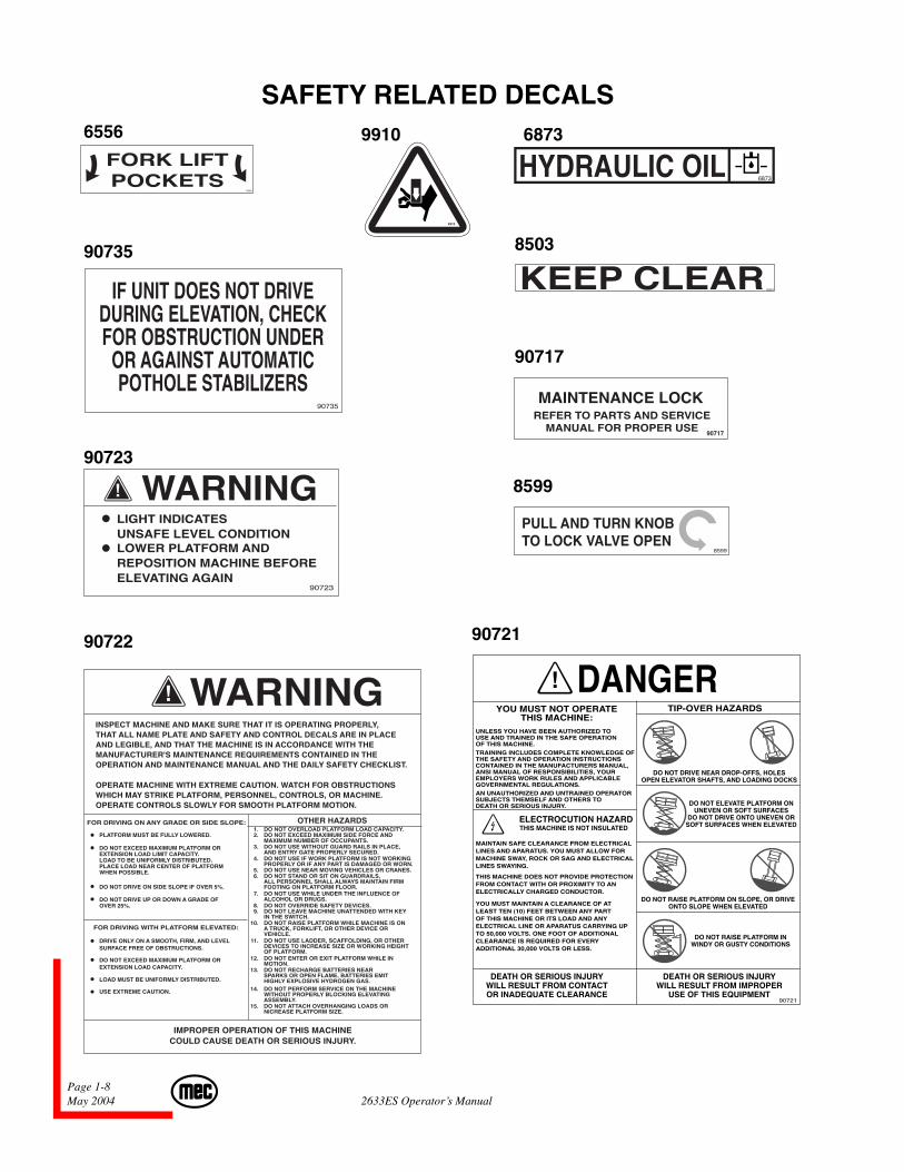
SAFETY RELATED DECALS6556 6873
90735
90723
90722
8503
90721
8599
90717
IF UNIT DOES NOT DRIVEDURING ELEVATION, CHECKFOR OBSTRUCTION UNDER
OR AGAINST AUTOMATICPOTHOLE STABILIZERS
90735
INSPECT MACHINE AND MAKE SURE THAT IT IS OPERATING PROPERLY,THAT ALL NAME PLATE AND SAFETY AND CONTROL DECALS ARE IN PLACEAND LEGIBLE, AND THAT THE MACHINE IS IN ACCORDANCE WITH THEMANUFACTURER'S MAINTENANCE REQUIREMENTS CONTAINED IN THEOPERATION AND MAINTENANCE MANUAL AND THE DAILY SAFETY CHECKLIST.
OPERATE MACHINE WITH EXTREME CAUTION. WATCH FOR OBSTRUCTIONSWHICH MAY STRIKE PLATFORM, PERSONNEL, CONTROLS, OR MACHINE.OPERATE CONTROLS SLOWLY FOR SMOOTH PLATFORM MOTION.
FOR DRIVING ON ANY GRADE OR SIDE SLOPE:
FOR DRIVING WITH PLATFORM ELEVATED:
PLATFORM MUST BE FULLY LOWERED.
DO NOT EXCEED MAXIMUM PLATFORM OREXTENSION LOAD LIMIT CAPACITY.LOAD TO BE UNIFORMLY DISTRIBUTED.PLACE LOAD NEAR CENTER OF PLATFORMWHEN POSSIBLE.
DO NOT DRIVE ON SIDE SLOPE IF OVER 5%.
DO NOT DRIVE UP OR DOWN A GRADE OFOVER 25%.
DRIVE ONLY ON A SMOOTH, FIRM, AND LEVELSURFACE FREE OF OBSTRUCTIONS.
DO NOT EXCEED MAXIMUM PLATFORM OREXTENSION LOAD CAPACITY.
LOAD MUST BE UNIFORMLY DISTRIBUTED.
USE EXTREME CAUTION.
OTHER HAZARDS
IMPROPER OPERATION OF THIS MACHINECOULD CAUSE DEATH OR SERIOUS INJURY.
1. DO NOT OVERLOAD PLATFORM LOAD CAPACITY.2. DO NOT EXCEED MAXIMUM SIDE FORCE AND
MAXIMUM NUMBER OF OCCUPANTS.3. DO NOT USE WITHOUT GUARD RAILS IN PLACE,
AND ENTRY GATE PROPERLY SECURED.4. DO NOT USE IF WORK PLATFORM IS NOT WORKING
PROPERLY OR IF ANY PART IS DAMAGED OR WORN.5. DO NOT USE NEAR MOVING VEHICLES OR CRANES.6. DO NOT STAND OR SIT ON GUARDRAILS,
ALL PERSONNEL SHALL ALWAYS MAINTAIN FIRMFOOTING ON PLATFORM FLOOR.
7. DO NOT USE WHILE UNDER THE INFLUENCE OFALCOHOL OR DRUGS.
8. DO NOT OVERRIDE SAFETY DEVICES.9. DO NOT LEAVE MACHINE UNATTENDED WITH KEY
IN THE SWITCH.10. DO NOT RAISE PLATFORM WHILE MACHINE IS ON
A TRUCK, FORKLIFT, OR OTHER DEVICE ORVEHICLE.
11. DO NOT USE LADDER, SCAFFOLDING, OR OTHERDEVICES TO INCREASE SIZE OR WORKING HEIGHTOF PLATFORM.
12. DO NOT ENTER OR EXIT PLATFORM WHILE INMOTION.
13. DO NOT RECHARGE BATTERIES NEARSPARKS OR OPEN FLAME, BATTERIES EMITHIGHLY EXPLOSIVE HYDROGEN GAS.
14. DO NOT PERFORM SERVICE ON THE MACHINEWITHOUT PROPERLY BLOCKING ELEVATINGASSEMBLY.
15. DO NOT ATTACH OVERHANGING LOADS ORNICREASE PLATFORM SIZE.
8599
TIP-OVER HAZARDSYOU MUST NOT OPERATETHIS MACHINE:
DO NOT DRIVE NEAR DROP-OFFS, HOLESOPEN ELEVATOR SHAFTS, AND LOADING DOCKS
DO NOT ELEVATE PLATFORM ONUNEVEN OR SOFT SURFACES
DO NOT DRIVE ONTO UNEVEN ORSOFT SURFACES WHEN ELEVATED
DO NOT RAISE PLATFORM ON SLOPE, OR DRIVEONTO SLOPE WHEN ELEVATED
DO NOT RAISE PLATFORM INWINDY OR GUSTY CONDITIONS
DEATH OR SERIOUS INJURYWILL RESULT FROM IMPROPER
USE OF THIS EQUIPMENT
DEATH OR SERIOUS INJURYWILL RESULT FROM CONTACTOR INADEQUATE CLEARANCE
90721
ELECTROCUTION HAZARDTHIS MACHINE IS NOT INSULATED
UNLESS YOU HAVE BEEN AUTHORIZED TOUSE AND TRAINED IN THE SAFE OPERATIONOF THIS MACHINE.TRAINING INCLUDES COMPLETE KNOWLEDGE OFTHE SAFETY AND OPERATION INSTRUCTIONSCONTAINED IN THE MANUFACTURERS MANUAL,ANSI MANUAL OF RESPONSIBILITIES, YOUREMPLOYERS WORK RULES AND APPLICABLEGOVERNMENTAL REGULATIONS.AN UNAUTHORIZED AND UNTRAINED OPERATORSUBJECTS THEMSELF AND OTHERS TODEATH OR SERIOUS INJURY.
MAINTAIN SAFE CLEARANCE FROM ELECTRICALLINES AND APARATUS. YOU MUST ALLOW FORMACHINE SWAY, ROCK OR SAG AND ELECTRICALLINES SWAYING.
THIS MACHINE DOES NOT PROVIDE PROTECTIONFROM CONTACT WITH OR PROXIMITY TO ANELECTRICALLY CHARGED CONDUCTOR.
YOU MUST MAINTAIN A CLEARANCE OF ATLEAST TEN (10) FEET BETWEEN ANY PARTOF THIS MACHINE OR ITS LOAD AND ANYELECTRICAL LINE OR APARATUS CARRYING UPTO 50,000 VOLTS. ONE FOOT OF ADDITIONALCLEARANCE IS REQUIRED FOR EVERYADDITIONAL 30,000 VOLTS OR LESS.
9910
Page 1-92633ES Operator’s Manual May 2004
LOCATE CONTROL BOX HERE
FOR NORMAL OPERATION OF THIS UNIT7155
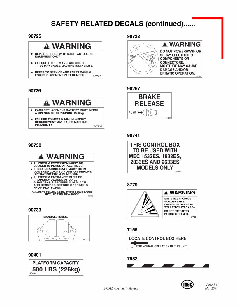
SAFETY RELATED DECALS (continued)......
90725 90732
90726 90267
90730
90741
8779
90733
REFER TO SERVICE AND PARTS MANUALFOR REPLACEMENT PART NUMBER. 90725
REPLACE TIRES WITH MANUFACTURER'SEQUIPMENT ONLY.
FAILURE TO USE MANUFACTURER'STIRES MAY CAUSE MACHINE INSTABILITY.
90726
EACH REPLACEMENT BATTERY MUST WEIGHA MINIMUM OF 60 POUNDS / 27.3 kg
FAILURE TO MEET MINIMUM WEIGHTREQUIREMENT MAY CAUSE MACHINEINSTABILITY
PLATFORM ENTRANCE MUST BEPROPERLY CLOSED AND ALLGUARDRAILS PROPERLY IN PLACEAND SECURED BEFORE OPERATINGFROM PLATFORM.
90730
PLATFORM EXTENSION MUST BELOCKED IN PLACE AT ALL TIMES.SHEET LOADING GATE MUST BE INLOWERED LOCKED POSITION BEFOREOPERATING FROM PLATFORM.
FAILURE TO FOLLOW INSTRUCTIONS COULD CAUSEDEATH OR PERSONAL INJURY
MANUALS INSIDE
90733
DO NOT POWERWASH ORSPRAY ELECTRONICCOMPONENTS ORCONNECTORE.MOISTURE MAY CAUSEDAMAGE AND/ORERRATIC OPERATION.
90732
THIS CONTROL BOXTO BE USED WITH
MEC 1532ES, 1932ES,2033ES AND 2633ES
MODELS ONLY90741
90401
7155
7982
Page 1-10May 2004 2633ES Operator’s Manual
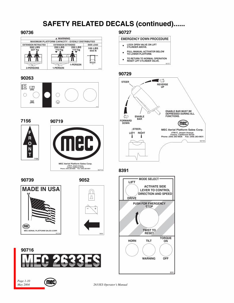
SAFETY RELATED DECALS (continued)......90736 90727
90263
7156
90729
90719
90739
8391
90716
90736
MAXIMUM PLATFORM CAPACITY - EVENLY DISTRIBUTED
EXTENSION RETRACTED EXTENSION EXTENDED SIDE LOAD500 LBS227 kg
250 LBS113 kg
250 LBS113 kg 100 LBS
444 N
2-PERSONS 1-PERSON1-PERSON
EMERGENCY DOWN PROCEDURE
LOCK OPEN VALVE ON LIFTCYLINDER ABOVE.
PULL MANUAL ACTIVATOR BELOWTO LOWER PLATFORM.
TO RETURN TO NORMAL OPERATIONRESET LIFT CYLINDER VALVE.
90727
9052
Page 2-12633ES Operator’s Manual May 2004
SECTION 2:OPERATION
Page 2-2May 2004 2633ES Operator’s Manual
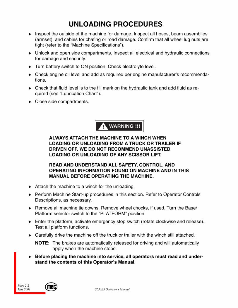
UNLOADING PROCEDURES♦ Inspect the outside of the machine for damage. Inspect all hoses, beam assemblies
(armset), and cables for chafing or road damage. Confirm that all wheel lug nuts aretight (refer to the “Machine Specifications”).
♦ Unlock and open side compartments. Inspect all electrical and hydraulic connectionsfor damage and security.
♦ Turn battery switch to ON position. Check electrolyte level.
♦ Check engine oil level and add as required per engine manufacturer’s recommenda-tions.
♦ Check that fluid level is to the fill mark on the hydraulic tank and add fluid as re-quired (see “Lubrication Chart”).
♦ Close side compartments.
ALWAYS ATTACH THE MACHINE TO A WINCH WHENLOADING OR UNLOADING FROM A TRUCK OR TRAILER IFDRIVEN OFF. WE DO NOT RECOMMEND UNASSISTEDLOADING OR UNLOADING OF ANY SCISSOR LIFT.
READ AND UNDERSTAND ALL SAFETY, CONTROL, ANDOPERATING INFORMATION FOUND ON MACHINE AND IN THISMANUAL BEFORE OPERATING THE MACHINE.
♦ Attach the machine to a winch for the unloading.
♦ Perform Machine Start-up procedures in this section. Refer to Operator ControlsDescriptions, as necessary.
♦ Remove all machine tie downs. Remove wheel chocks, if used. Turn the Base/Platform selector switch to the “PLATFORM” position.
♦ Enter the platform, activate emergency stop switch (rotate clockwise and release).Test all platform functions.
♦ Carefully drive the machine off the truck or trailer with the winch still attached.
NOTE: The brakes are automatically released for driving and will automaticallyapply when the machine stops.
♦ Before placing the machine into service, all operators must read and under-stand the contents of this Operator’s Manual.
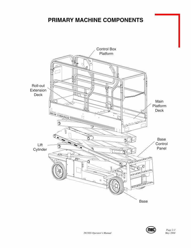
Page 2-32633ES Operator’s Manual May 2004
Control BoxPlatform
MainPlatform
Deck
BaseControlPanel
Base
Roll-outExtension
Deck
LiftCylinder
PRIMARY MACHINE COMPONENTS
Page 2-4May 2004 2633ES Operator’s Manual
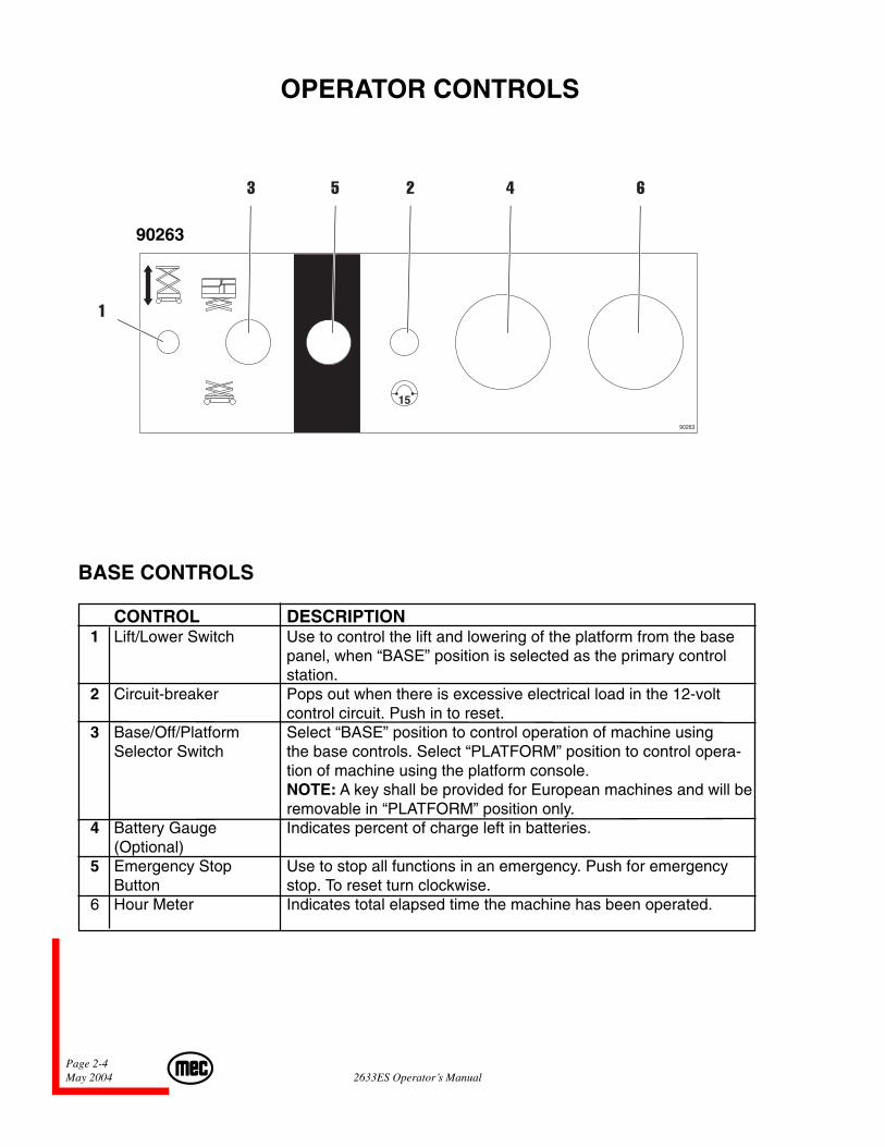
OPERATOR CONTROLS
BASE CONTROLS
CONTROL DESCRIPTION 1 Lift/Lower Switch Use to control the lift and lowering of the platform from the base
panel, when “BASE” position is selected as the primary controlstation.
2 Circuit-breaker Pops out when there is excessive electrical load in the 12-voltcontrol circuit. Push in to reset.
3 Base/Off/Platform Select “BASE” position to control operation of machine usingSelector Switch the base controls. Select “PLATFORM” position to control opera-
tion of machine using the platform console.NOTE: A key shall be provided for European machines and will beremovable in “PLATFORM” position only.
4 Battery Gauge Indicates percent of charge left in batteries.(Optional)
5 Emergency Stop Use to stop all functions in an emergency. Push for emergencyButton stop. To reset turn clockwise.
6 Hour Meter Indicates total elapsed time the machine has been operated.
1
3 5 2 4 6
90263
Page 2-52633ES Operator’s Manual May 2004
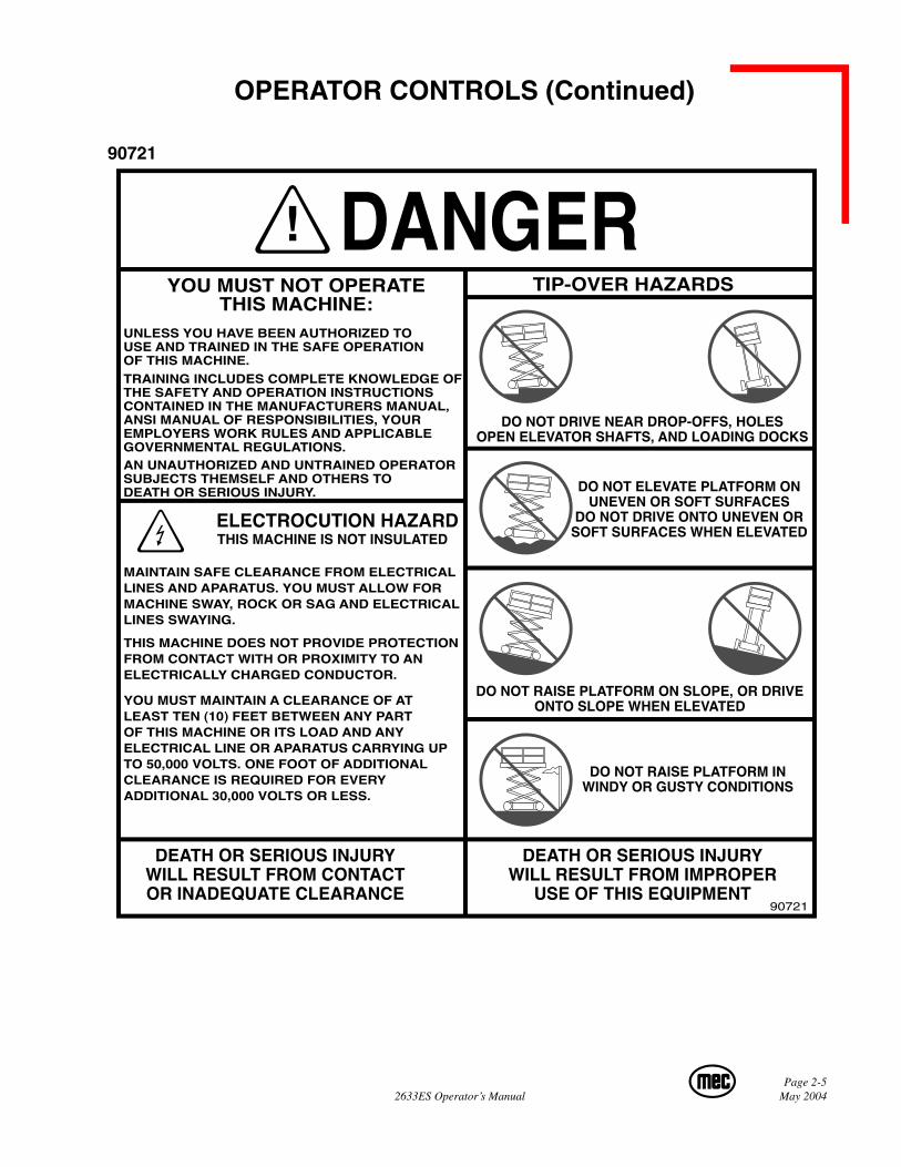
90721
TIP-OVER HAZARDSYOU MUST NOT OPERATETHIS MACHINE:
DO NOT DRIVE NEAR DROP-OFFS, HOLESOPEN ELEVATOR SHAFTS, AND LOADING DOCKS
DO NOT ELEVATE PLATFORM ONUNEVEN OR SOFT SURFACES
DO NOT DRIVE ONTO UNEVEN ORSOFT SURFACES WHEN ELEVATED
DO NOT RAISE PLATFORM ON SLOPE, OR DRIVEONTO SLOPE WHEN ELEVATED
DO NOT RAISE PLATFORM INWINDY OR GUSTY CONDITIONS
DEATH OR SERIOUS INJURYWILL RESULT FROM IMPROPER
USE OF THIS EQUIPMENT
DEATH OR SERIOUS INJURYWILL RESULT FROM CONTACTOR INADEQUATE CLEARANCE
90721
ELECTROCUTION HAZARDTHIS MACHINE IS NOT INSULATED
UNLESS YOU HAVE BEEN AUTHORIZED TOUSE AND TRAINED IN THE SAFE OPERATIONOF THIS MACHINE.TRAINING INCLUDES COMPLETE KNOWLEDGE OFTHE SAFETY AND OPERATION INSTRUCTIONSCONTAINED IN THE MANUFACTURERS MANUAL,ANSI MANUAL OF RESPONSIBILITIES, YOUREMPLOYERS WORK RULES AND APPLICABLEGOVERNMENTAL REGULATIONS.AN UNAUTHORIZED AND UNTRAINED OPERATORSUBJECTS THEMSELF AND OTHERS TODEATH OR SERIOUS INJURY.
MAINTAIN SAFE CLEARANCE FROM ELECTRICALLINES AND APARATUS. YOU MUST ALLOW FORMACHINE SWAY, ROCK OR SAG AND ELECTRICALLINES SWAYING.
THIS MACHINE DOES NOT PROVIDE PROTECTIONFROM CONTACT WITH OR PROXIMITY TO ANELECTRICALLY CHARGED CONDUCTOR.
YOU MUST MAINTAIN A CLEARANCE OF ATLEAST TEN (10) FEET BETWEEN ANY PARTOF THIS MACHINE OR ITS LOAD AND ANYELECTRICAL LINE OR APARATUS CARRYING UPTO 50,000 VOLTS. ONE FOOT OF ADDITIONALCLEARANCE IS REQUIRED FOR EVERYADDITIONAL 30,000 VOLTS OR LESS.
OPERATOR CONTROLS (Continued)
Page 2-6May 2004 2633ES Operator’s Manual
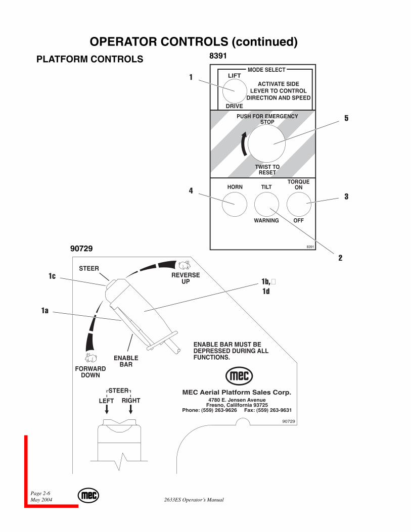
OPERATOR CONTROLS (continued)PLATFORM CONTROLS
90729
8391
1
5
3
2
4
1c
1a
1b,�1d
Page 2-72633ES Operator’s Manual May 2004
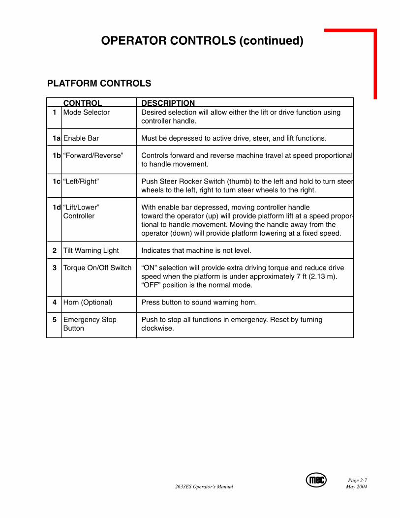
OPERATOR CONTROLS (continued)
PLATFORM CONTROLS
CONTROL DESCRIPTION 1 Mode Selector Desired selection will allow either the lift or drive function using
controller handle.
1a Enable Bar Must be depressed to active drive, steer, and lift functions.
1b “Forward/Reverse” Controls forward and reverse machine travel at speed proportionalto handle movement.
1c “Left/Right” Push Steer Rocker Switch (thumb) to the left and hold to turn steerwheels to the left, right to turn steer wheels to the right.
1d “Lift/Lower” With enable bar depressed, moving controller handleController toward the operator (up) will provide platform lift at a speed propor-
tional to handle movement. Moving the handle away from theoperator (down) will provide platform lowering at a fixed speed.
2 Tilt Warning Light Indicates that machine is not level.
3 Torque On/Off Switch “ON” selection will provide extra driving torque and reduce drivespeed when the platform is under approximately 7 ft (2.13 m).“OFF” position is the normal mode.
4 Horn (Optional) Press button to sound warning horn.
5 Emergency Stop Push to stop all functions in emergency. Reset by turningButton clockwise.
Page 2-8May 2004 2633ES Operator’s Manual
PRESTART INSPECTIONBefore use each day or at the beginning of each shift, the machine shall be given a visualinspection and functional test. Repairs (if any) must be made prior to operating the machineas it is critical to ensure safe operation of the machine.
♦ Visually inspect all machine components; for loose or missing parts, hydraulic fluid leaks, loose or damaged wires. Check for structural or weld cracks.
♦ Check fluid levels with the platform fully lowered.
♦ Check the wheel lug nuts for tightness (Refer to “Machine Specifications”).
♦ Check that all warning and instructional labels are legible and secure.
♦ Check the platform guard rail system. Insure platform entry properly closes andsecures.
♦ Ensure that emergency stop buttons on the base control panel and the platformcontrols are disengaged. Reset by turning clockwise.
♦ Ensure that the battery disconnect switch is in the “ON” position.
MACHINE START UP
1. Ensure the battery disconnect switch, located on Base Control Box, is in the “ON”position.
2. Place the base/platform select switch to the desired position.
3. The machine can now be operated from the selected position.
NOTE: If the machine fails to operate, inspect the motor controller inside the motorcompartment. A green LED located on the controller should be illuminated.If the LED is not illuminated, refer to the troubleshooting section.
Page 2-92633ES Operator’s Manual May 2004
BASE CONTROL OPERATION AND CHECKS
♦♦♦♦♦ ELECTROCUTION HAZARD!!! THIS MACHINE IS NOT INSULATED!!
Maintain safe clearance from electrically charged conductors (power lines) andapparatus. You must allow for machine sway (side to side movement) when elevatedand electrical line movement. This machine does not provide protection from contactwith, or proximity to, an electrically charged conductor.
BE SURE AREA ABOVE THE MACHINE IS CLEAR OFOBSTRUCTIONS TO ALLOW FULL ELEVATION OF PLATFORM.
DO NOT OPERATE THE MACHINE IF THE FOLLOWINGCHECKS REVEAL A DEFECT.
♦ Turn selector switch to “BASE” position.
♦ Activate the Lift/ Lower switch on the base control panel to elevate the platform tothe end of its movement. Releasing the switch should stop elevation.
♦ Test the “Emergency Stop” function. While the platform is moving, press the Emer-gency Stop button, platform should stop.
♦ Reset by rotating clockwise.
♦ Lower the platform about halfway by switching the Lift/ Lower switch. Releasing theswitch should stop the lowering.
♦ Check for proper operation and hydraulic leaks. Rotate the maintenance lock intoposition before inspecting any items inside or around scissor arms.
♦ Rotate the maintenance lock into position. Lower platform to the stowed position.
Page 2-10May 2004 2633ES Operator’s Manual
PLATFORM CONTROL OPERATION AND CHECKS
♦ Select the “Platform” position on the selector switch at base control station.
♦ Enter platform and close and secure the entry.
♦ Press the horn button briefly to check if working properly, if installed.
IMPORTANT: The Enable Bar must be activated to operate the controller forDrive, Steer, and Lift/ Lower Function.
♦ Check for proper operation and hydraulic fluid leaks.
♦ Move mode selector switch to “Lift” position, depress Enable bar and movecontrol handle “up” (toward the operator).
♦ Test emergency stop function by pressing down on the red Emergency Stop switch.Reset by rotating clockwise.
♦ To lower platform, depress the Enable bar and move control handle “down”(away from the operator).
IF PLATFORM SHOULD FAIL TO LOWER DO NOT ATTEMPT TOCLIMB DOWN THE BEAM ASSEMBLY. SERIOUS INJURY MAYRESULT.
IMPORTANT: Always check front steer wheel direction before driving.
♦ Move mode select switch to “Drive” position. Test Left/ Right steering by depressingEnable bar on control handle and pressing the rocker switch at the top of the handle.Press left side of switch for left steer direction and right side for right steer direction.
♦ Move the mode select switch to “Drive” position, depress Enable bar and movecontrol handle “forward” and “backward” to check drive direction. Releasing theEnable bar or returning control handle to center position will stop motion of drive.
♦ Test the “Emergency Stop” function. While driving in both directions. Reset “Emer-gency Stop” by rotating the switch clockwise.
Page 2-112633ES Operator’s Manual May 2004
OPERATION
THE OPERATOR MUST BE AWARE OF THE ENVIRONMENT.DO NOT RAISE THE PLATFORM IF THE MACHINE IS NOT ON AFIRM LEVEL SURFACE.
SAFE OPERATION BEGINS WITH A SAFETY CONSCIOUSEQUIPMENT OPERATOR.
Perform prestart inspection. Remember to place the selector switch in the “Platform” posi-tion before getting in the platform for operation.
DRIVING AND STEERING
CHECK THAT THE ROUTE OF TRAVEL TO BE TAKEN ISCLEAR OF PERSONS, OBSTRUCTIONS, DEBRIS, HOLES, ANDDROP OFFS, AND IS CAPABLE OF SUPPORTING THEMACHINE.
NOTE: To activate drive function, activate mode selector switch in “Drive”position. Depressing the Enable bar, drive and steer functions can beachieved. Steer wheels will not center themselves after a turn, and must bereturned to the straight-ahead position with the steer switch.
Controller handle movement “away” from the operator will give FORWARD travel andpulling the handle “towards” the operator will give REVERSE travel.
Travel speed is proportional and is controlled by the movement of the controller handle.The further it is moved the faster the speed will be. The controller handle returns to neutral(center) position when released.
Page 2-12May 2004 2633ES Operator’s Manual
BRAKING
ACTIVATION OF THE PLATFORM “EMERGENCY STOP”BUTTON WILL APPLY BRAKES IMMEDIATELY. THIS MAYCAUSE UNEXPECTED PLATFORM MOVEMENT AS THEMACHINE COMES TO A SUDDEN STOP. BRACE YOURSELFAND SECURE OBJECTS ON THE PLATFORM DURINGOPERATION OF MACHINE.
NOTE: For parking, the brake is automatically applied when the forward/reversedrive controller is positioned in the center (neutral) position.
ELEVATING THE PLATFORM
USING PLATFORM CONTROLS
To elevate the platform, activate mode selector switch in the “Lift” position. Depressing theEnable bar and moving controller handle “towards” the operator will elevate the platform.Rate of lift is proportional and is dependent on the movement of the controller handle.
USING BASE CONTROLS
With selector switch in the “Base” position, press and hold the Lift/ Lower toggle switch onthe base control panel in the “Up” position until the desired height is reached or until theplatform reaches maximum height.
LOWERING THE PLATFORM
USING PLATFORM CONTROLS
To lower the platform, activate mode selector switch to the “Lift” position. Depressing theEnable bar and moving the controller handle “away” from the operator will lower the plat-form. Rate of descent is fixed - platform lowers at same rate regardless of handle position.
USING BASE CONTROLS
With selector switch in the “Base” position, press and hold the Lift/ Lower toggle switch inthe “Down” position until the desired platform height is reached or until the platform reachesthe stowed position.
Page 2-132633ES Operator’s Manual May 2004
EXTENDING THE ROLL-OUT EXTENSION DECK
♦ Lift handle at the rear of the extension deck to raise spring-loaded pin from thelocked position.
♦ With handle raised, push the deck out to the desired extended length and releasethe handles for the spring-loaded pin to lock into position.
♦ Extensions can be achieved in intervals of 6 inches (15 cm) throughout the entirelength of the roll-out extension deck.
IF THE ROLL-OUT DECK IS EXTENDED CHECK FORCLEARANCE UNDER DECK AREA BEFORE LOWERINGPLATFORM.
CHARGING THE BATTERIES
LEAD-ACID BATTERIES GENERATE EXPLOSIVE GASES.KEEP SPARKS AND FLAME AWAY FROM BATTERIES.
NO SMOKING !
♦ Plug the battery charger into 115 volt, 60 Hz AC outlet, using #12 AWG groundedextension cord to recharge the batteries.
To determine if the batteries are fully charged, plug the charger in. The LED indicat-ing 2/3 charge illumination within a few minutes indicates that the batteries are fullycharged.
DO NOT OPERATE THE UNIT WHILE CHARGING.
BE SURE TO DISCONNECT THE CHARGER FROM THEOUTLET BEFORE MOVING THE UNIT.
Page 2-14May 2004 2633ES Operator’s Manual
SHUTDOWN PROCEDURE♦ When finished with the machine, place the platform in the stowed position.
♦ Park the machine on a level surface.
♦ Carefully exit the platform using a constant three (3) point dismount/grip.
♦ Place selector switch at base control panel in the “Off” position.
NOTE: Leaving the selector switch in the base or platform position for an extendedtime will drain the battery. Always put the selector switch in “Off” positionwhen leaving the machine at the end of the work day.
♦ Put a padlock on the battery disconnect switch to prevent unauthorized operation.
MOVING THE MACHINEMachine can be winched or moved short distances in case of power failure at speeds not toexceed 5 MPH (8.05 kph).
TOWING/ WINCHING THE MACHINE
Your machine is equipped with a brake release.
PRIOR TO MANUALLY RELEASING BRAKES, INSUREWHEELS ARE CHOCKED TO PREVENT MACHINE FROMMOVING.
Release Brakes Before Towing:
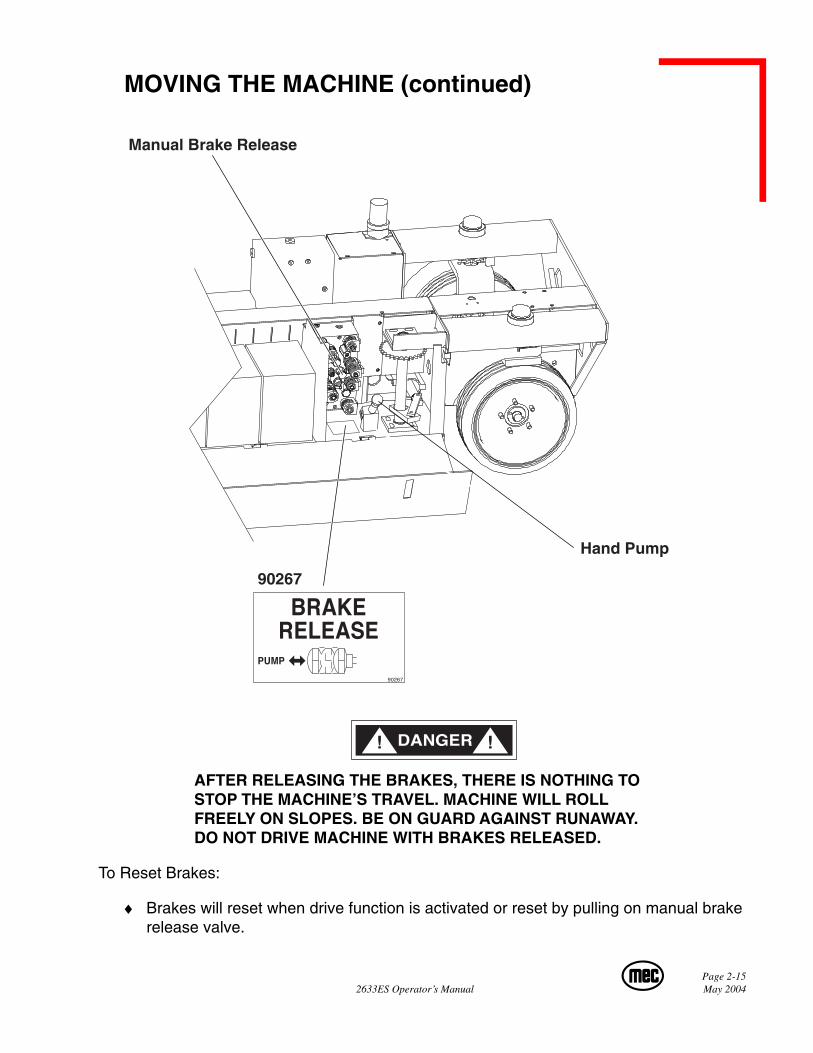
♦ Push in the manual brake release valve located on the main manifold.
♦ Using the hand pump in the battery compartment, pump valve until pressure is built.
♦ Machine is now ready for towing.
Page 2-152633ES Operator’s Manual May 2004
Hand Pump
90267
Manual Brake Release
AFTER RELEASING THE BRAKES, THERE IS NOTHING TOSTOP THE MACHINE’S TRAVEL. MACHINE WILL ROLLFREELY ON SLOPES. BE ON GUARD AGAINST RUNAWAY.DO NOT DRIVE MACHINE WITH BRAKES RELEASED.
To Reset Brakes:
♦ Brakes will reset when drive function is activated or reset by pulling on manual brakerelease valve.
MOVING THE MACHINE (continued)
Page 2-16May 2004 2633ES Operator’s Manual
EMERGENCY SYSTEMS AND PROCEDURES
IF THE CONTROL SYSTEM FAILS WHILE THE PLATFORM ISELEVATED, HAVE AN EXPERIENCED OPERATOR USE THEEMERGENCY LOWERING PROCEDURE TO SAFELY LOWERTHE PLATFORM.
NEVER CLIMB DOWN BEAM ASSEMBLY WHEN PLATFORM ISRAISED.
BEFORE LOWERING PLATFORM RETRACT THE DECKEXTENSION.
Page 2-172633ES Operator’s Manual May 2004
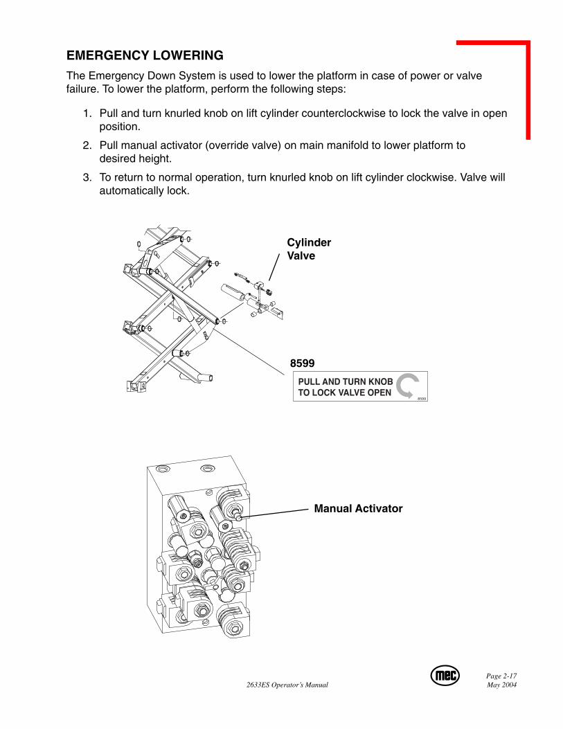
EMERGENCY LOWERING
The Emergency Down System is used to lower the platform in case of power or valvefailure. To lower the platform, perform the following steps:
1. Pull and turn knurled knob on lift cylinder counterclockwise to lock the valve in openposition.
2. Pull manual activator (override valve) on main manifold to lower platform todesired height.
3. To return to normal operation, turn knurled knob on lift cylinder clockwise. Valve willautomatically lock.
8599
CylinderValve
Manual Activator
8599

Page 2-18May 2004 2633ES Operator’s Manual

Page 3-12633 Operator’s Manual May 2004
SECTION 3:MAINTENANCE
Page 3-2May 2004 2633ES Operator’s Manual
GENERAL MAINTENANCE TIPSRegular inspection and conscientious maintenance is the key to efficient economical opera-tion of your scissor lift. It will help to assure that your equipment will perform satisfactorilywith a minimum of service and repair.
The actual operating environment of the machine governs the inspection schedule. Correctlubrication is an essential part of the preventative maintenance to minimize wear on work-ing parts and ensure against premature failure. By maintaining correct lubrication, thepossibility of mechanical failure and resulting downtime is reduced to a minimum.
NEVER PERFORM SERVICE ON THE MACHINE (WITH THEPLATFORM ELEVATED) WITHOUT FIRST BLOCKING THEBEAMS (SCISSORS) ASSEMBLY IN PLACE USING THEMAINTENANCE LOCK!
♦ Block scissors assembly using maintenance lock if machine is in the elevated/ex-tended position.
♦ Never leave hydraulic components or hoses open. They must be protected fromcontamination (including rain) at all times.
♦ Never open a hydraulic system when there are contaminants in the air.
♦ Always clean the surrounding area before opening hydraulic systems.
♦ Use only recommended lubricants. Improper lubricants or incompatible lubricantsmay be as harmful as no lubrication.
♦ Watch for makeshift “fixes” which can jeopardize safety as well as lead to morecostly repair.
Page 3-32633ES Operator’s Manual May 2004
GENERAL MAINTENANCE TIPS (Continued)........
HYDRAULIC FLUID UNDER PRESSURE CAN PENETRATE ANDBURN SKIN, DAMAGE EYES, AND MAY CAUSE SERIOUSINJURY, BLINDNESS, AND EVEN DEATH.CORRECT LEAKS IMMEDIATELY.
Failure to perform preventive maintenance at recommendedintervals may result in the unit being operated with a defectthat could result in injury or death of the operator.
Immediately report to your supervisor any Defect ormalfunction. Any defect shall be repaired prior to continueduse of the scissor lift.
Inspection and maintenance should be performed by qualifiedpersonnel familiar with the equipment.
Fluid leaks under pressure may not always be visible. Checkfor pin hole leaks with a piece of cardboard, not your hand.
Page 3-4May 2004 2633ES Operator’s Manual
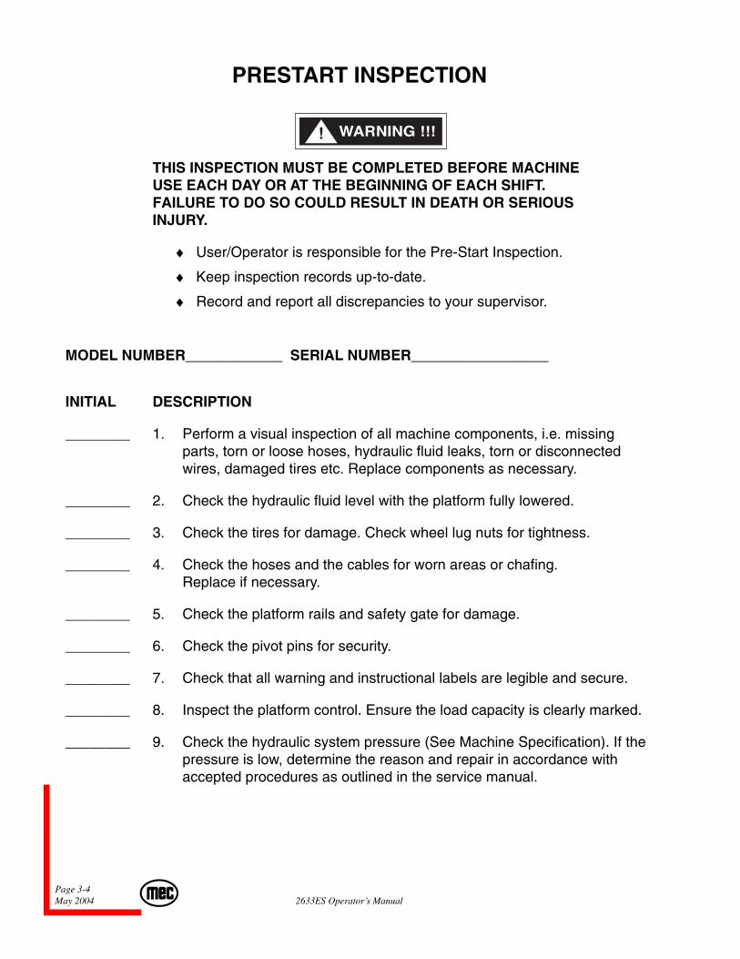
PRESTART INSPECTION
THIS INSPECTION MUST BE COMPLETED BEFORE MACHINEUSE EACH DAY OR AT THE BEGINNING OF EACH SHIFT.FAILURE TO DO SO COULD RESULT IN DEATH OR SERIOUSINJURY.
♦ User/Operator is responsible for the Pre-Start Inspection.
♦ Keep inspection records up-to-date.
♦ Record and report all discrepancies to your supervisor.
MODEL NUMBER____________ SERIAL NUMBER_________________
INITIAL DESCRIPTION
________ 1. Perform a visual inspection of all machine components, i.e. missingparts, torn or loose hoses, hydraulic fluid leaks, torn or disconnectedwires, damaged tires etc. Replace components as necessary.
________ 2. Check the hydraulic fluid level with the platform fully lowered.
________ 3. Check the tires for damage. Check wheel lug nuts for tightness.
________ 4. Check the hoses and the cables for worn areas or chafing.Replace if necessary.
________ 5. Check the platform rails and safety gate for damage.
________ 6. Check the pivot pins for security.
________ 7. Check that all warning and instructional labels are legible and secure.
________ 8. Inspect the platform control. Ensure the load capacity is clearly marked.
________ 9. Check the hydraulic system pressure (See Machine Specification). If thepressure is low, determine the reason and repair in accordance withaccepted procedures as outlined in the service manual.
Page 3-52633ES Operator’s Manual May 2004
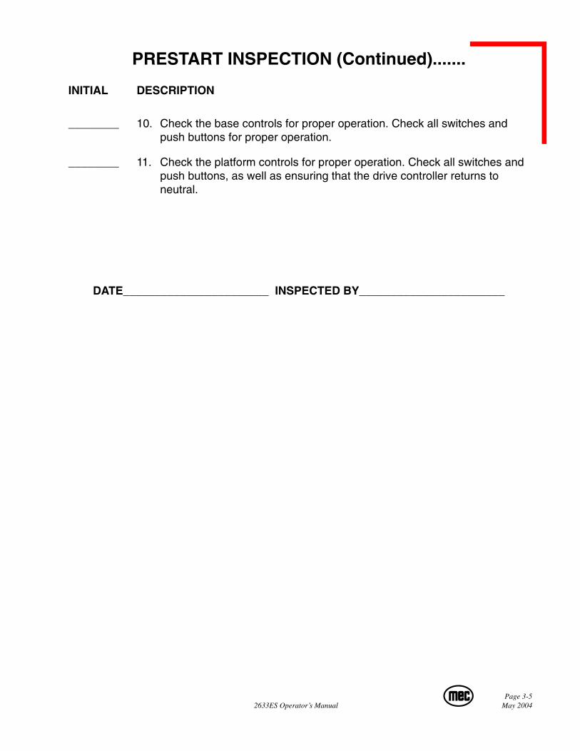
PRESTART INSPECTION (Continued).......
INITIAL DESCRIPTION
________ 10. Check the base controls for proper operation. Check all switches andpush buttons for proper operation.
________ 11. Check the platform controls for proper operation. Check all switches andpush buttons, as well as ensuring that the drive controller returns toneutral.
DATE_______________________ INSPECTED BY_______________________
Page 3-6May 2004 2633ES Operator’s Manual
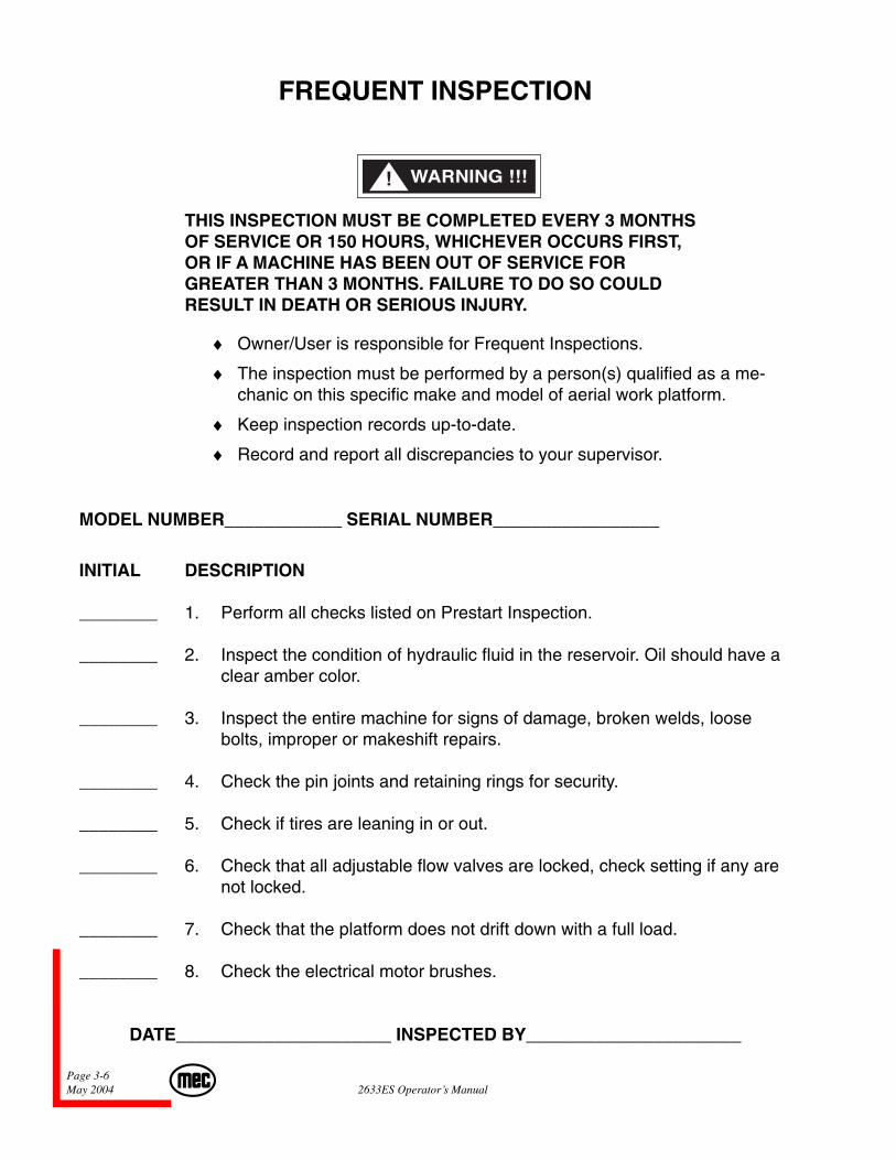
FREQUENT INSPECTION
THIS INSPECTION MUST BE COMPLETED EVERY 3 MONTHSOF SERVICE OR 150 HOURS, WHICHEVER OCCURS FIRST,OR IF A MACHINE HAS BEEN OUT OF SERVICE FORGREATER THAN 3 MONTHS. FAILURE TO DO SO COULDRESULT IN DEATH OR SERIOUS INJURY.
♦ Owner/User is responsible for Frequent Inspections.
♦ The inspection must be performed by a person(s) qualified as a me-chanic on this specific make and model of aerial work platform.
♦ Keep inspection records up-to-date.
♦ Record and report all discrepancies to your supervisor.
MODEL NUMBER____________ SERIAL NUMBER_________________
INITIAL DESCRIPTION
________ 1. Perform all checks listed on Prestart Inspection.
________ 2. Inspect the condition of hydraulic fluid in the reservoir. Oil should have aclear amber color.
________ 3. Inspect the entire machine for signs of damage, broken welds, loosebolts, improper or makeshift repairs.
________ 4. Check the pin joints and retaining rings for security.
________ 5. Check if tires are leaning in or out.
________ 6. Check that all adjustable flow valves are locked, check setting if any arenot locked.
________ 7. Check that the platform does not drift down with a full load.
________ 8. Check the electrical motor brushes.
DATE______________________ INSPECTED BY______________________
Page 3-72633ES Operator’s Manual May 2004
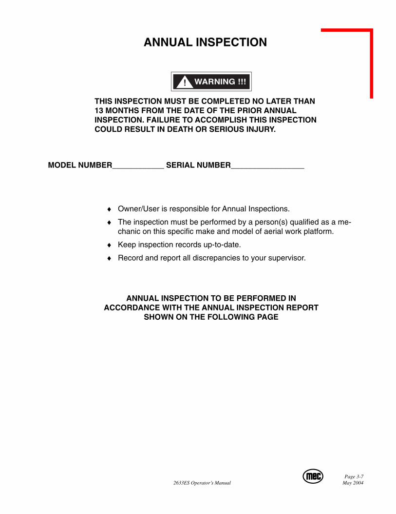
ANNUAL INSPECTION
THIS INSPECTION MUST BE COMPLETED NO LATER THAN13 MONTHS FROM THE DATE OF THE PRIOR ANNUALINSPECTION. FAILURE TO ACCOMPLISH THIS INSPECTIONCOULD RESULT IN DEATH OR SERIOUS INJURY.
MODEL NUMBER____________ SERIAL NUMBER_________________
♦ Owner/User is responsible for Annual Inspections.
♦ The inspection must be performed by a person(s) qualified as a me-chanic on this specific make and model of aerial work platform.
♦ Keep inspection records up-to-date.
♦ Record and report all discrepancies to your supervisor.
ANNUAL INSPECTION TO BE PERFORMED INACCORDANCE WITH THE ANNUAL INSPECTION REPORT
SHOWN ON THE FOLLOWING PAGE

Page 3-8May 2004 2633ES Operator’s Manual
Decals:�Proper Placement/Quantity�Legibility�Correct Capacity Noted
Rails:�All Rail Fasteners Secure�Rear Gate Closes Properly�Manual/Safety Data In Tube�Rear Rail Pad In Place
Extending Platform:�Pivots Freely�Latches In Stowed Position�Latches In Extended Position�Rail Latches Work Properly�Cables Secure�Deck Board Secure
Platform:�Bolts For Pivot Shaft Secure�Platform Bolts Tight�Extension Shaft Secure�Deck Board Secure�Platform Structure
Wire Harnesses:�Mounted Correctly�Physical Appearance�110V Outlet Safe/Working
Scissors:�Beam Structures�Welds�Retaining Rings�Upper Cylinder Pins Secure�Lower Cylinder Pins Secure�Lower Beam Mounts tight�Rollers Turn Freely
Maintenance Locks:�Secure�Operational
Base:�Cover Panels Secure�Base Fasteners Tight�Bolts Tight�Front Axle Mounting Bolts�Rear Axle Mounting Bolts
Drive Assembly:�Wheel Motors Secure�Steering Cylinder Pins Secure�Pivot Points Lubed
Drive Assembly Front Hubs:�Torqued To At Least 300 ft/lbs�Cotter Pinned
Rear Axle:�Brake Cylinder Pinned�Brakes Operational�Brake Pads Secure�Brakes Properly Adjusted�Brake Lock Operational�Brake Rods Lubed�Hub/Spindle Lubed�Brake Drum Clean�Castle Nut Secure/Cotter Pinned
Component Area:�Valve Manifold(s) Secure�Hoses Tight/No Leaks�D/C Mtr(s) Secure/Operational�Contactors Secure�Pump Secure
Batteries:�Secure�Fully Charged
Battery Charger:�Secure�Operational
Emergency Stop:�Breaks All Circuits
Operation:�Wires Tight�Switches Secure�All Functions Operational
Emergency Down:�Operational
Slow Speed Limit Switch:�Set Properly
Pothole Bars:�Operate Smoothly�Lock In Place�Limit Switches Adjusted
Pressures & Hydraulics:�Oil Filter Secure/Chg�Oil Level Correct/Chg�Steering Pressure Set�Drive Pressurre Set�Lift Pressure Set
Engine:�Engine Mounts Tight�Fuel Lines Secure�Fuel Lines Free Of Leaks�Fuer Tanks Secure�Fuel Shut Off Valves Func.�All Shields/Guards In Place
Oil Level:�Correct/Chg�Oil�Air
Options Operational:�Hour Meter�Battery Indicator�Warning Light�Warning Horn�Tilt Sensor�Generator�Converter
Y N R Y N R Y
Key: "Y" Yes/Acceptable"N" No/Unacceptable"R" Repaired
N R
Comments:
Signature/Mechanic:Signature/Owner-User:
Date:Date:
White Copy - Dealer Yellow Copy - Customer P/N 90728 Rev. 0
• Check each item listed below.• Use proper Operating, Service, and �
Maintenance manual for specific information and settings.• If an item is found to be "Unacceptable" make the necessary�
repairs and check the "Repaired" box.• When all items are "Acceptable", the unit is ready for service.
CustomerStreetCity/State/ZipPhone NumberContact
DealerStreetCity/State/ZipPhone NumberContact
DateSerial NumberModel NumberDate Of Last InspectionDate Placed In Service
Annual InspectionReport
Aerial Platform Sales Corp.4780 E. Jensen Ave. • Fresno, CA 93725(866) 379-7278 • Fax (559) 263-9631
Page 3-92633ES Operator’s Manual May 2004
TROUBLESHOOTING
SHOULD YOU EXPERIENCE ERRATIC OPERATION ORNOTICE ANY MALFUNCTION WHILE OPERATING THISMACHINE, DISCONTINUE USE IMMEDIATELY.
CALL FOR ASSISTANCE AND REPORT THE INCIDENT TOYOUR SUPERVISOR, AND DO NOT USE THE MACHINEUNTIL IT HAS BEEN CHECKED BY A TRAINED, QUALIFIEDMECHANIC.
WHAT TO CHECK IF FUNCTIONS WILL NOT OPERATE:
♦ Battery cutoff switch?
♦ Is a function toggle switch or the enable switch not activated?
♦ Is the Base/Off/Platform switch in the proper position?
♦ Batteries fully charged?
♦ Check emergency stop buttons at both base and platform?
♦ Hydraulic fluid level low?
♦ Obvious fluid leak or damaged component?
♦ Are any wires pulled out or loose?
Page 3-10May 2004 2633ES Operator’s Manual
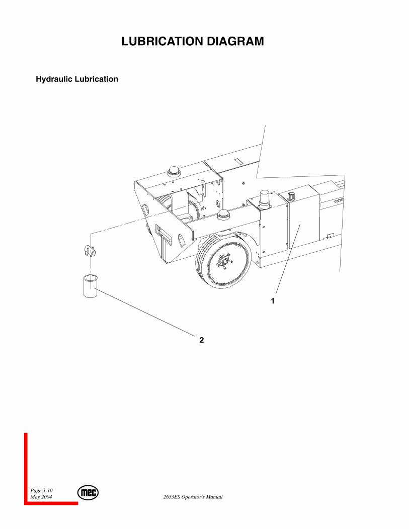
LUBRICATION DIAGRAM
Hydraulic Lubrication
2
1
Page 3-112633ES Operator’s Manual May 2004
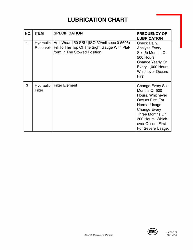
SPECIFICATION
Anti-Wear 150 SSU (ISO 32/mil spec 0-5606)Fill To The Top Of The Sight Gauge With Plat-form In The Stowed Position.
Filter Element
FREQUENCY OFLUBRICATIONCheck Daily.Analyze EverySix (6) Months Or500 Hours.Change Yearly OrEvery 1,000 Hours,Whichever OccursFirst.
Change Every SixMonths Or 500Hours, WhicheverOccurs First ForNormal Usage.Change EveryThree Months Or300 Hours, Which-ever Occurs FirstFor Severe Usage.
LUBRICATION CHART
ITEM
HydraulicReservoir
HydraulicFilter
NO.
1
2

Page 3-12May 2004 2633ES Operator’s Manual

Limited Owner Warranty
MEC Aerial Platform Sales Corp. warrants its equipment to the original purchaser againstdefects in material and/or workmanship under normal use and service for one (1) yearfrom date of registered sale or date the unit left the factory if not registered. MEC AerialPlatform Sales Corp. further warrants the structural weldments of the main frame andscissor arms to be free from defects in material or workmanship for five (5) years fromdate of registered sale or date unit left the factory if not registered. Excluded from suchwarranty is the battery(s) which carries a ninety (90) day warranty from describedpurchase date. Warranty claims within such warranty period shall be limited to repair orreplacement, MEC Aerial Platform Sales Corp’s option, of the defective part in questionand labor to perform the necessary repair or replacement based on MEC Aerial PlatformSales Corp’s then current flat rate, provided the defective part in question is shippedprepaid to MEC Aerial Platform Sales Corp. and is found upon inspection by MEC AerialPlatform Sales Corp. to be defective in material and/or workmanship. MEC AerialPlatform Sales Corp. shall not be liable for any consequential, incidental or contingentdamages whatsoever. Use of other than factory authorized parts; misuse, impropermaintenance, or modification of the equipment voids this warranty. The foregoingwarranty is exclusive and in lieu of all other warranties, express or implied. All suchother warranties, including implied warranties of merchantability and of fitness for aparticular purpose, are hereby excluded. No Dealer, Sales Representative, or other personpurporting to act on behalf of MEC Aerial Platform Sales Corp. is authorized to alter theterms of this warranty, or in any manner assume on behalf of MEC Aerial Platform SalesCorp. any liability or obligation which exceeds MEC Aerial Platform Sales Corp’sobligations under this warranty.
Aerial Platforms Sales Corp.4780 E. Jensen Ave. • Fresno, CA 93725 USAPh: 1-866-379-7278 • 559-263-9626 • Fax: 559-263-9631www.mecawp.com