Embed Size (px)
Citation preview

SYNERGY – e-RECRUITMENT SYSTEM
By
Ankur Kapila
Reg No: 41502621004
Of
SRM Engineering College
A PROJECT REPORT
Submitted to the
FACULTY OF INFORMATION TECHNOLOGY AND COMMUNICATION ENGINEERING
In partial fulfillment of the requirements for the award of the degree
of
MASTER OF COMPUTER APPLICATION
June 2005
ABSTRACT
WIPRO has always recognized the need for a highly secured e-recruitment system,
which can decrease the amount of time taken for recruiting as well as reduce the hectic work of
the recruiters.
It is enabled through the intranet and Internet and can be accessed from anywhere in
the world, anytime and hence its focus is on “anytime, anyplace Recruitment”. It is used as the
interface between all classes of users through the e-recruitment process namely the recruiters,
panelists, students etc.
With the growth in the Software industry, the demand for fresh talent has been ever
increasing. Mass recruitment of freshers is now happening more that ever before. In the case of
recruiting a lot of freshers for the organizational needs, the present System is very tedious and has
a long process which consumes a lot of cycle time and energy of the Recruitment Team.
Therefore my objective would be to enhance the capabilities of ‘Synergy’ by addition
of a new module ‘Wipro University’ which would specifically be designed to meet the needs of
recruitment of freshers. The new module would be developed with the inputs from the
recruitment team, synergy team, and taking the existing system a base.
The System would be developed as per the J2EE architecture, using the model-view-
controller (MVC) design pattern. The different modules in the system will be developed using this
architecture. The applications will consist of Data Access Objects, Servlets, JSPs (Java Server
Pages), JavaScript, Java Beans and EJB (Enterprise Java Beans).Front-end screens will be
developed using Java Server Pages and the backend data will be stored using Oracle 8i.

ACKNOWLEDGEMENTS
I thank Prof. R. Venkatramani, Principal, SRM Engineering College, who gave me
this wonderful opportunity to exhibit my excellence, even though he was not directly involved in
the project but his presence was felt throughout.
I thank Prof. S. Sagayaraj, Head of Department of Computer Application, SRM
Engineering College, provided a moral support for doing my project with valuable suggestions
and guidance. Apart from the project phase, my period of being a student under him was an
education.
I thank my internal guide Asst. Prof. M. Shantha, Department of Computer
Application, SRM Engineering College, for her effort, valuable guidance, suggestions, and
constant encouragement throughout my project work.
I am indebted to my external guide Mrs. Sapna Nagaraj, Senior Project Manager,
Wipro Technologies, Bangalore, sharing her knowledge, experience, and taking personal
interest which creating excellent environment that perfectly exposed me to the world of Software
Development.
I am grateful to Mr. Girish C Nair, Project Manager and Mr. Sandesh Prabhu,
Test leader, Wipro Technologies, Bangalore, who were always there to clear all the doubts for
their valuable suggestions, cooperation and patience while doing my project work.
I wish to express my indebtedness to my beloved family members, especially my
father, mother, brother and all my friends for their unfailing moral support, without which I could
never be studying this MCA course.

TABLE OF CONTENTS
Title Page No
ABSTRACT iv
LIST OF TABLES xi
LIST OF FIGURES xii
LIST OF ABBREVIATIONS xiii
1. INTRODUCTION 1
1.1 About the Organization 1
1.2 Organizational Structure 2
1.3 Recruitment in Wipro 4
1.4 E-Recruitment System – ‘Synergy’ 4
2. PROBLEM DEFINITION AND FEASIBLITY ANALYSIS 6
2.1 Problem Definition 6
2.2 Existing System 6
2.2.1 Limitations of Existing System 7
2.3 Proposed System 8
2.3.1 Objectives of the Proposed System 8
2.3.1.1 My Perspective 8
2.3.1.2 Wipro’s Perspective 8
2.4 Requirement Analysis 9
2.4.1 Overview 9
2.4.2 Source of Requirements 9
2.4.3 Stake Holders 9
2.4.4 Process and functionalities identified 9
2.4.4.1 Job Creation 10
2.4.4.2 Test Creation 10
Title Page No
2.4.4.3 Resume Posting 11
2.4.4.4 Assign Test Id’s 11
2.4.4.5 Test Confirmation 12
2.4.4.6 Resume Processing 12
2.4.4.7 SAP Transfer 12
2.4.5 Functional Requirements 13
2.4.6 Non-functional Requirements 13
2.4.6.1 Usability 13
2.4.6.2 Compatibility 14
2.4.6.3 Performance 14
2.4.6.4 Scalability 14
2.4.6.5 Security 14
2.5 Scope of Work 14
2.5.1 Wipro University Module 14
2.6 Feasibility Analysis 15
2.6.1 Operational Feasibility 15
2.6.2 Technical Feasibility 15
2.6.3 Economical Feasibility 15
3. SOFTWARE REQUIREMENTS SPECIFICATION 16
3.1 Introduction 16
3.1.1 Purpose 16
3.1.2 Scope 16
3.2 General Description 16
3.2.1 User Perspective 16
3.2.2 Developer Perspective 17
3.3 Specific Requirements 18
3.3.1 Behavioral Requirements 18

3.3.2 Software Requirements 18
3.3.2.1 User 18
3.3.2.2 Developer 18
3.3.2.3 Server 18
3.3.3 Hardware Requirements 19
3.3.3.1 User 19
3.3.3.2 Developer 19
3.3.3.3 Server 19
3.4 System Attributes 19
3.4.1 Security 19
3.4.2 Maintainability 20
3.4.3 Portability 20
3.4.4 Reliability 20
3.4.5 Re-Usability 20
3.4.6 Efficiency 20
4. SYSTEM ENVIRONMENT 21
4.1 iPlanet Application Server 21
4.1.1 iPlanet Application Server Product Family 21
4.1.2 iPlanet Process Manager 21
4.1.3 iPlanet Application Builder 22
4.1.4 Key Features of Application Model 22
4.2 J2EE Concepts 22
4.3 Servlets 24
4.3.1 Types of Servlets 24
4.4 Java Server Pages 25
4.5 Enterprise Java Beans 26
4.5.1 Role in iPlanet Application Server Applications 26
4.5.2 EJB Interface Logic 26
4.5.3 Session Bean and Entity Bean 26
4.6 Data Access Components 27

4.6.1 Business Data Object 28
4.6.2 Data Access Objects 28
4.6.3 Data Source 28
5. SYSTEM DESIGN – PRELIMINARY 29
5.1 Introduction 29
5.2 Basic Design Approach 29
5.3 Design Concepts 30
5.3.1 Modularity 30
5.3.2 Functional Independence 30
5.3.3 Cohesion and Coupling 31
5.4 User Interface Design 31
5.5 Database Design 32
5.5.1 Normalization 32
5.6 Input / Output Design 33
5.6.1 Input Design 33
5.6.2 Output Design 34
6. SYSTEM DESIGN – DETAILED 35
6.1 Introduction 35
6.2 Database Design 35
6.2.1 Table Descriptions 36
6.2.2 Database Diagram 38
6.3 Data Flow Diagrams 39
7. CODING, TESTING AND IMPLEMENTATION 43
7.1 Coding 43
7.2 Testing 44
7.2.1 Unit Testing 45
7.2.2 Integration Testing 45
7.2.3 Validation Testing 46

Title Page No
7.2.4 Acceptance Testing 46
7.3 Implementation 46
7.4 Integration Issues 47
8. CONCLUSION AND FORESEEABLE ENHANCEMENTS 48
8.1 Conclusion 48
8.2 Foreseeable Enhancements 49
APPENDIX 1 - SCREEN SHOTS (Selected) 50
REFERENCES 59
LIST OF TABLES
Table No. Description Page No
2.1 Stake Holders of the Wipro University 9
2.2 Wipro University Job Creation 10
2.3 Wipro University Test Creation 10
2.4 Wipro University Resume Posting 11
2.5 Wipro University Assign Test 11
2.6 Wipro University Test Confirmation 12
2.7 Wipro University Process Resumes 12
2.8 Wipro University SAP Transfer 13
4.1 iPlanet Application Server Components 22

LIST OF FIGURES
Figure Description Page No
Fig 3.1 Block diagram of E-Recruitment System 17
Fig 4.1 Multi-Tiered Architecture 23
Fig 4.2 Data flow in a Multi-tier Model 24
Fig 4.3 Servlets Response-Request call 25
Fig 4.4 Model View Controller Design Pattern 26
Fig 4.5 Class Diagram for DAO pattern relationships 28
Fig 6.1 Database Diagram 38
Fig 6.2 DFD - User Login 39
Fig 6.3 DFD - Job Creation 39
Fig 6.4 DFD - Test Creation 40
Fig 6.5 DFD - Resume Posting 40
Fig 6.6 DFD - Assign Test 41
Fig 6.7 DFD - Test Confirmation 41
Fig 6.8 DFD - Resume Processing 42
Fig 6.9 DFD - SAP Transfer by Recruiter 42
Fig A 1.1 Job Create Screen 50
Fig A 1.2 Test Create Screen 51
Fig A 1.3 Assign Test Query Screen 52
Fig A 1.4 Assign Test Screen 53
Fig A 1.5 Query Screen – Process Candidates 54
Fig A 1.6 Process Candidates Screen (in part) 55
Fig A 1.7 Process Candidates Screen (contd.) 55
Fig A 1.8 SAP Transfer Screen 56
Fig A 1.9 Resume Posting Screen 57
Fig A 2.0 Candidate Desktop 58

LIST OF ABBREVIATIONS
Abbreviation Description
API Application Program Interface
B2B Business to Business
BPO Business Process Outsourcing
DAO Data Access Object
DFD Data Flow Diagram
DRM Divisional Resource Manager
EJB Enterprise Java Beans
ERP Enterprise Resource Planning
HR Human Resource
iAB iPlanet Application Builder
iAS iPlanet Application Server
IE Internet Explorer
J2EE Java 2 Enterprise Edition
JDBC Java Database Connectivity
JDK Java Development Kit
JSP Java Server Pages
MVC Model-View-Controller
NYSE New York Stock Exchange
OODBMS Object Oriented Database Management System
PAS People Allocation System
PCMM People Capability Maturity Model
RDBMS Relational Database Management System
SAP System Application Products in Data Processing
SEI Software Engineering Institute
SMS Short Messaging Service
URL Uniform Resource Locator
WAP Wireless Application Protocol

CHAPTER 1
INTRODUCTION
1.1 ABOUT THE ORGANIZATION
Wipro Ltd. being a world leader in providing IT services is focused to provide robust
software professionals. The unique selection processes brings out the best in the industry based
on its quality and expertise. Wipro translates every person into reliable and resourceful future
world leaders that catapult them way ahead of competition. Wipro has implemented value added
services to the world in different forms.
Wipro Ltd. is the first PCMM Level 5 and SEI CMM Level 5 certified IT Services
Company globally. Wipro provides comprehensive IT solutions and services, including systems
integration, Information Systems outsourcing, package implementation, software application
development and maintenance, and research and development services to corporations globally.
Wipro’s business units are Wipro Technologies, Wipro InfoTech, Wipro Consumer and Lighting,
Wipro Spectramind (now Wipro BPO).
Wipro Technologies is the global technology services division of Wipro Ltd.
(NYSE:WIT). Wipro Technologies offer a full portfolio of services across industries, delivering
measurable business benefits to the customers with six-sigma consistency. Wipro is the world's
first software services company to attain SEI Level 5 certification for software quality. Wipro has
business offices in North America, West Europe and Japan and development centers in India,
USA and UK.
Wipro Technologies today has come a long way from the time when it started off
by selling software products in the Indian market. Today its customer base is global, its employee
force is spread across the world, its equity and standing in the software services market is not a
small matter.

Wipro Technologies offers services in distinct areas which are as follows:-
• The IT Services aims at empowering the enterprise. From getting e-businesses up and
going to managing technology infrastructure, the company is focused on helping
businesses do their business better.
• The Product Design Services help companies bring defect-free products into market, in
time and within budget.
• The Service Provider Solutions address the specialized needs of the market by
providing a complete business and technology offering.
WIPRO “Applying Thought” - We promise our customers with utmost respect to
Human Values, we promise to serve our customer with Integrity through Innovation, Value
for money, solutions by Applying Thought day after day.
1.2 ORGANISATIONAL STRUCTURE
The organization structure of Wipro Technologies can be conceptually viewed as six
categories:-
• Communicating values to customers through Sales and Marketing
Sales and Marketing combined communicate Wipro’s valued added proposition to
customers, manage existing customer relationships, create new ones and coordinate the
value flow from the delivery teams to the customers.
• Executing and Delivering Values through Vertical Domains
Vertical domains represent the market segment – focused business units, which actually
execute the value proposition by delivering software services and solutions to a wide range
of customers in diverse markets. The vertical domains constitute horsepower of the

organization such as retails, corporate Wipro, Finance and Banking, Insurance, Govt.
Solutions, Wireless Services and Carrier Network Services.
• Working with verticals to facilitate E-Enabling solutions
Horizontals like “E-enabling Solutions” are organized around “Practices” which focus on
developing expertise in specific identified areas like Mobile Commerce. These “Practices”
work closely with the vertical business units in delivering value to the customers.
• Enterprise-Wide supporting Services
Central Support functions constitute horizontal functions, which provide services to the
rest of the organization. Their nature could be vastly different while the quality is the
nodal group for directing all quality initiatives and ensuring adherence to quality standards,
the Operations Support group provides physical infrastructure facilities like telephones,
transport, etc.
• Enterprise-Wide initiatives and innovation
A dynamic organization like Wipro Technologies needs to keep reinventing itself and
infuse the necessary competitive capabilities. At any given point of time, the organization
has few initiatives running which are enterprise-wide in impact and represent a strong
building block for the organization of the future such as Knowledge Management and
Innovation Initiatives.
• Physical Location Points of value creation-Development centers
Development Centers represent the physical locations where the actual delivery of
software services happens. Each city-center will have its own dedicated infrastructure. The
number of development centers for WT is expected to expand to more cities with the
objective of tapping and grooming talent locally all over India.

1.3 RECRUITMENT IN WIPRO
The planning for every division / location is on the basis of an overall manpower
plan construed at the beginning of every financial year by the respective business heads. This
manpower plan is specific to each business unit within the division and is apportioned
accordingly, based on the manpower need for each month of the financial year for both
experienced recruits and new employees.
The People Allocation System (PAS) and the Pool / Plan recruitment (Plan) should
be the focal point for day to day planning of recruitment activities for each division / location,
which is construed, based on skill forecast/profile forecast and is the micro version of the overall
manpower plan.
Every Divisional Resource Manager (DRM) has to communicate and validate the
regional plan for each of the regions namely Delhi and Mumbai at the beginning of every month
within the parameters of the overall regional recruitment plan in the format enclosed.
Every Divisional Resource Manager (DRM) should plan all recruitment against the
source plan and grade plan arrived at for each of the defined sources.
1.4 E-RECRUITMENT SYSTEM – ‘SYNERGY’
The e-recruitment system ‘Synergy’ handles the whole of the recruitment process for
Wipro Technologies, Wipro Infotech, and Wipro BPO. By making the process E-enabled there is
no flow of documents from one location to another and this also saves the overall cycle time for
the whole process. This project also removes any type of location dependency in the overall
recruitment process.
WIPRO maintains a fully integrated end-to-end web enabled system, which integrates
with third party systems namely PAS (requirement information), SAP (offer data), TEDWEB

(employee referral); Source Desktops (jobs view), Finance (auto vendor payment) and Job Sites
(post resumes).
It is enabled through the intranet and Internet and can be accessed from anywhere in
the world, anytime and hence its focus is on “Anytime, Anyplace Recruitment”. It is used as
the interface between all classes of users through the e-recruitment process namely the recruiters,
panelists, college student etc.
The Recruitment Systems project has different modules, each module serving
different functional and technical aspects of the recruitment process to achieve end-to-end
automation of recruitment process of the organization.
CHAPTER 2
PROBLEM DEFINITION AND FEASIBILITY ANALYSIS
2.1 PROBLEM DEFINITION
The e-Recruitment System is specifically developed to cater to the recruitment
requirements of Wipro Ltd. The application handles the whole flow of employee hiring in Wipro
Technologies, Wipro Infotech and Wipro BPO. The system was developed with an aim to reduce
the manual processes involved in recruitment to bare minimum, by and large making the process
e-enabled reducing the flow of documents from one location to another and reducing overall
cycle time.
As with any live project the requirements are never static, they keep on changing during its lifetime. Any successful project not only caters the current requirements, but should be flexible enough to accommodate the changing requirements otherwise it would become obsolete. It should be scalable both vertically and horizontally, by vertically scalability we mean that it should be able to incorporate totally new requirements and functionality which were not there during its development, by horizontal scalability we mean that it should be able incorporate changes in the existing processes being handled by it.

‘Synergy’ is an excellent system which handles almost all aspects of recruitment process and is constantly evolving to meet the changing requirements. This can be amply demonstrated by the existence of this project.
2.2 EXISTING SYSTEM
The e-recruitment system ‘Synergy’ handles the whole of the recruitment process for
Wipro Technologies, Wipro Infotech, and Wipro BPO. Its a fully integrated end-to-end web
enabled system, which integrates with third party systems namely PAS (requirement information),
SAP (offer data), TEDWEB (employee referral), Source Desktops (jobs view), Finance (auto
vendor payment) and Job Sites (post resumes).
It is enabled through the intranet and Internet and can be accessed from anywhere in
the world, anytime and hence its focus is on “Anytime, Anyplace Recruitment”. It is used as
the interface between all classes of users through the E-recruitment process namely the recruiters,
panelists, College Students, etc.
The Recruitment Systems project has different modules, each module serving
different functional and technical aspects of the recruitment process to achieve end-to-end
automation of recruitment process of the organization.
2.2.1 Limitations of Existing System
With the growth in the Software industry, the demand for fresh talent has been ever
increasing. Mass recruitment of freshers is now happening more that ever before. In the case of
recruiting a lot of Fresher for the Organizational needs, the present System is very tedious and has
a long process which consumes a lot of Cycle Time and energy for the Recruitment Team. This is
primarily because the recruitment system and process followed was for the recruitment of
individual candidates, involving various procedures and processes which are either not required or
not appropriate for mass hiring’s. For example, a candidate can have up to five technical and two
HR interviews in synergy, while for a fresher only one technical and one HR interview is
sufficient.

Challenges for fresher recruitment:
• Large amount of people to be recruited.
• Different process to be followed.
• Creation of tests.
• Date and time based resume posting.
• Auto population of details.
• Criteria based searching, of resumes.
• Automated confirmation.
2.3 PROPOSED SYSTEM
Recruitment is a major activity in Wipro Technologies, Wipro InfoTech and Wipro
Spectramind. All the Recruitment activities happen through Synergy – an internal web-enabled
Recruitment System developed by Information Systems Team of Wipro Technologies.
In the case of recruiting a lot of Fresher for the Organizational needs, the present System is very
tedious and has a very long process which will consume a lot of time and energy of the
Recruitment Team. Hence, the need is for the Wipro University recruitment feature.
2.3.1 Objective of the Proposed System
2.3.1.1 My Perspective
Here, my main Objective is to enhance the existing Recruitment System of Wipro
Ltd. by adding of a module namely - Wipro University. With the addition of new features I aim at
the following:
• Enable Wipro to recruit the best available talent in the Industry

• Reduce the Cycle time of Hiring
• Cater to the need of Mass Hiring of Freshers
2.3.1.2 Wipro’s Perspective
From Wipro’s perspective, this dissertation work will provide value added features
which can be used by all the companies of Wipro Limited for Recruitment Purposes. So
enhancing the e-Recruitment system would improve the quality of the worldwide Recruitment
Activities happening in Wipro Limited.
2.4 REQUIREMENT ANALYSIS
2.4.1 Overview
Currently recruitment process for freshers system is only partly automated. Recruiters
manually plan for Tests, ask Candidates to attend the Test. The resumes of selected candidates are
updated in synergy manually from there on the automated process takes on which takes care of
scheduling of interviews and selection process till the selected candidates get offered and finally
join the company.
2.4.2 Source of Requirement
The requirement would be gathered with constant input from the
Manager – Strategic Resourcing and his Team Members.
2.4.3 Stake Holders
No. Stakeholder Role of the Stakeholder

1 Recruitment Team
- Resource Managers,
- Recruiters,
- Support Personnel
Responsible for the overall recruitment
process.
2 Candidates Candidates are responsible for Posting
Resumes and Taking Tests
Table 2.1 Stake Holders of the Wipro University
2.4.4 Processes and Functionalities Identified
Based on the inputs from the Recruitment Team, the following process has been
identified for Wipro University as summarized below.
2.4.4.1 Job Creation
The creation of Wipro University jobs would be done by the recruiter as per requirements.
No. Action Taken System Response 1 Recruiter logs in and uses a Job
Create feature
Job should be created only for the
Permissible Division, Sub-Division,
Location and Experience Band.
2 Recruiter fills in the Job Details or
had chosen Auto fill option and
clicks on Submit
Job would get created and Job Code would
be displayed. Job Code should be available
in the Career Site till the date of closure.
Table 2.2 Wipro University Job Creation
2.4.4.2 Test Creation

Test’s need to be created for Wipro University jobs, before the job becomes available
and the resumes can be posted against it. Any number of test’s can be created for a job.
No. Action Taken System Response
1 System Admin logs in and uses the
Create Test Id feature where-in
he/she fills in all the Test Details
and clicks on Submit.
Test Id should get generated.
Table 2.3 Wipro University Test Creation
2.4.4.3 Resume Posting
Candidates should be able to view the jobs for which tests have been created and post
resumes against those jobs.
No. Action Taken System Response
1 Search and View Jobs All the jobs based on the search criteria should be displayed
2 Apply against job by posting of resumes.
Reference number identifying the candidate and resume to be generated. Also unique user id, and password generated to be sent to the mail id of candidate
Table 2.4 Wipro University Resume Posting

2.4.6.1 Assigning Test-Id’s
The recruiter should be able to view and assign test id to resumes posted against his
permissible jobs. An option to search the resumes based on specific criteria’s as per his
requirements should also be provided. Mails would be sent to the candidate informing them the
test schedule and venue details.
Step Action Taken System Response
1 Recruiter logs in and uses assign
Test Id feature
Recruiter should get all the permissible Jobs
and the Resumes assigned to those Jobs
2 Resumes to be tagged to the Test
Ids
Mails would be sent to the Candidates
Table 2.5 Wipro University Assign Test
2.4.4.5 Test Confirmation
The candidate needs to confirm his appearance for the test, by logging in with his
user id and password mailed to him earlier. There should also be an option to capture the
candidate comments.
Step Action Taken System Response
1 Candidate logs in and confirms /
rejects the test.
Capture the candidate comments and
update the candidate response.
Table 2.6 Wipro University Test Confirmation

2.4.4.6 Resume Processing
Once the candidate has taken the test, the details of the test will be updated by the
recruiter. The candidate will be processed based on the selection criteria; a screen is to be
provided where the assessment details and status of candidate can be updated.
Step Action Taken System Response
1 Processing of test assigned
candidates
Assessment details and status to be sent to
the Candidates for selection
Table 2.7 Wipro University Process Resumes
2.4.4.7 SAP Transfer
Once the candidates have been offered, the recruiter can transfer the candidate details
to SAP using the SAP transfer feature.
Step Action Taken System Response
1 Recruiter logs in and uses the SAP
Transfer feature
All the offered Candidates would be
displayed
2 Recruiter fills in SAP Transfer
details and clicks on Submit.
Data would be sent to SAP and an
Applicant Id would get generated.
Table 2.8 Wipro University SAP Transfer
2.4.5 Functional Requirements
• The Mails in the System would be based on the mail formats provided by User
• The following templates are designed by me for implementation:
o Jobs - Creation and Modification Template
o Test Id - Creation and Modification template
o Assign Test Id – Query and Report Screen template
o Process Candidates – Query Screen template
o Process Candidates – Report Screen template
o Resume Posting – Jobs Query and Resume Details Template
• Appropriate Screens for all the processes identified above.
2.4.6 Non-functional Requirements
2.4.6.1 Usability
The users of the system are Recruitment Team, Candidates and Support Personnel.
• Should be User friendly, application to be used without any training.
• The user interface should be easy to start, work upon and to exit.
• Users should be able to come out of the System by clicking Logout link.
• At any point of time the User should be able to go to the Home Page
2.4.6.2 Compatibility
The design of the application should integrate seamlessly into the existing system,
providing the enhanced functionality without undue side affects.
2.4.6.3 Performance
The performance of the application should be fast. Whenever more records are to be
displayed the System should display only a set of records on the first request and should display
the subsequent sets on the subsequent requests
2.4.6.4 Scalability
This should be easily scalable to a bigger module which will take care of other related
activities, if any coming in the future.
2.4.6.5 Security
Each User should be validated against the User Id and password. The system should
ensure that only authorized people are allowed to enter into this system for their corresponding
activities.
2.5 SCOPE OF WORK
2.5.1 Wipro University Module
This module is geared towards the recruitment of freshers into Wipro Ltd. providing
the following features:-
• Creation of Jobs as per Requirements.
• Creating/modifying Test for jobs.
• Posting of Resumes by Candidates.
• Assigning Candidates to a Test.
• Confirmation of Test by Candidate
• Assessing the Candidates based on the Performance in the Test
• Offering the suitable Candidates after Technical and HR Interviews
2.6 FEASIBILITY ANALYSIS

It is important to evaluate the feasibility of a project in the initial phases of the project
so that scarcity of resources does not slow down development at a later stage. The main aim of
the feasibility analysis is to determine whether the project at hand is worth it both monetarily as
well as in terms of the effort.
The analysis comprised of the study of the following:-
• Operational Feasibility
• Technical Feasibility
• Economical Feasibility
2.6.1 Operational Feasibility
Since the developed system is user-friendly it is easy to operate and the programmer
finds it very easy to use. The operation is very easy and feasible. Hence the system is operationally
feasible.
2.6.2 Technical Feasibility
Since the system to be developed is an enhancement to the existing system, the
required software and hardware is already available. Hence the system is technically feasible.
2.6.3 Economic Feasibility
Since the system to be developed is an enhancement to the existing system, all the
required software and hardware is already available, therefore no expense is required for the
purchase of software and hardware. Hence the project is feasible with enormous gains in various
areas.

CHAPTER 3
SOFTWARE REQUIREMENTS SPECIFICATION
3.1 INTRODUCTION
3.1.1 Purpose
The Software Requirement Specification document is for the purpose of reference to
ensure that the requirements for the development and successful completion of the project are
met. It is an agreement between the customer and the developer that the specifications have been
clearly understood, the analysis been done properly and the design heading in the right direction.
3.1.2 Scope
Unless otherwise change is requested for, this document describes the
functionality, performance, constraints, interface and reliability for the entire life cycle of the
project.
3.2 GENERAL DESCRIPTION
3.2.1 User Perspective
The synergy provides easy interface and user can easily interact with system. Users are
provided with separate desktops, specially customized to their role, the desktop provides easy to
use dropdown menus that can be used access to various features quickly and easily. Help links are
provided throughout, which can be clicked to view the help file for the current screen in case the
user has some doubt.

3.2.2 Developer Perspective
The system provides a challenge for the developer because working on enhancements
of an existing system needs lot of patience and understanding of the existing system and
procedures. Exceptional programming skills in the relevant languages and understanding of the
various technical issues related is also required.
Fig 3.1 Block diagram of E- Recruitment System.
• Man Power
Indenting • Requirement
Generation
• Job Posting • Resume
Updation • Query/Search
Module • Interview
Scheduling Module
• Security • Planning And
Indenting Module
• Maintenance Module
• Offer Generation Module
• Campus • Reports
• Offer Generation
• Employee Profiles
• Joining • Invoicing
PAS/PLAN Requirements
Recruitment System
SAP
WOLTS
• Campus
Resumes with Test Results

3.3 SPECIFIC REQUIREMENTS
3.3.1 Behavioral Requirements
• The system should be able to provide means for efficient searching.
• The system should provide appropriate error, warning, and alert messages.
• The user interface should be standard and intuitive throughout.
• The system should enable reliability and correctness of data at any point of time.
• The system should incorporate all the validations and verifications.
3.3.2 Software Requirements
3.3.2.1 User
OS : Windows 9x/NT/XP/2000, Solaris, Linux.
Browsers : Netscape 4.6 / IE 5.0 or Compatible
3.3.2.2 Developer
OS : Windows NT/2000
Language : HTML, Java script, Java, EJB, Servlets
Compiler and Linker : JDK 1.2.2
Database : Oracle 8i
Application/Web Server : iAB / iAS 6.0/ iPlanet 4.1 Web Server
Browsers : Netscape 4.6 / IE 5.0 or compatible
3.3.2.3 Server
OS : Solaris 2.8
Language : HTML, Java script, Java, EJB, Servlets
Compiler and Linker : JDK 1.2.2
Database : Oracle 8i
Application/Web Server : iAB / iAS 6.0/iPlanet 4.1 Web Server

3.3.3 Hardware Requirements
3.3.3.1 User
System : IBM Compatible PC's
Processor : Pentium and above
RAM : 32 MB onwards
HDD : 2 GB
3.3.3.2 Developer
System : IBM Compatible PC's
Processor : PIII 600 MHz. or better
RAM : 256 Mb onwards
HDD : 10 GB
3.3.3.3 Server
System : IBM Compatible PC's
Processor : PIII 600 MHz. or better
RAM : 256 Mb onwards
HDD : 10 GB
3.4 SYSTEM ATTRIBUTES
3.4.1 Security
Security has to be enforced at all levels. It’s done by passwords, user rights checked at
all levels and encryption, and having a good security policy. Only hashed passwords are stored,
with only administrator being able to reset the passwords. Before a user is allowed to perform any
operation his rights are checked to make sure he is authorized to perform the operation. Security

policy is enforced by checking for weak passwords, forcing change of password after predefined
number of days, and not allowing past 5 passwords to be used again.
3.4.2 Maintainability
Provide logging of errors for locating and fixing an error. The modules are to be
clearly documented and possess the least degree of coupling so that they can be independently
modified.
3.4.3 Portability
The effort required to transfer a program from one hardware/software system environment to another. Synergy is developed using java technologies which are platform independent and since its online system the only client side requirement is a browser compatible with IE5.0 or Netscape 4.7.
3.4.4 Reliability
Reliability is the extent to which a program can be expected to perform its intended function under extreme circumstances with required precision. Synergy is fault tolerant and uses transactions to that guarantee data consistency to great extent.
3.4.5 Re-Usability
Code pertaining to the general functionalities can be reused since they are generic.
It helps in preventing the wastage of time spent in re-writing same code and functionality
which has already been developed and in use. In current scenario it would be java beans, EJB,
java script validations etc. that can be easily re-used.
3.4.6 Efficiency

The system should be highly efficient in providing the intended functionalities
through efficient code that puts minimum load on the system. The less the load system puts
on the server the better will be the performance of the server and greater amount of clients
the server can support.
CHAPTER 4
SYSTEM ENVIRONMENT
4.1 IPLANET APPLICATION SERVER
iPlanet Application Server software provides a most robust e-commerce platform for
delivering innovative and leading edge application services to a broad range of servers, clients, and
devices.
Built on a proven heritage of world-class scalability, reliability, and performance, the
iPlanet Application Server delivers on the requirements for global e-commerce success by
ensuring rapid time-to-market, and the ability to leverage information systems and business
processes across the extended enterprise.
4.1.1 iPlanet Application Server Product Family
In addition to the core application server, the iPlanet application Server Product line
includes a comprehensive set of products and tools to help quickly and efficiently create business
critical applications. These include:
4.1.2 iPlanet Process Manager

A comprehensive web-based designing, deploying, managing, and participating in
automated business processes such as claims management, customer self service, and order
fulfillment. An intuitive development environment and advanced scalability and reliability features
allow an enterprise to easily extend information on Enterprise Resource Planning (ERP) systems,
mainframes, and custom applications to employees, partners and suppliers.
4.1.3 iPlanet Application Builder
An Internet application development tool designed to simplify the creation of multi-
tiered enterprise-class applications that run on iPlanet Application Server. By targeting the
distributed multi-tier application model of iPlanet Application Server, iPlanet Application Builder
enables developers to rapidly build sophisticated, business-critical web applications for the
Internet.
4.1.4 Key Features of the Application Model
The iPlanet Application Server application model divides an application into multi
layers: Presentation, business logic, and data access. Presentation layer is further separated to
distinguish page layout and presentation logic. Data access refers to both databases and other data
sources.
Functionality in Application Application Components
Presentation Layout Servlets
Page Layout Java Server Pages
Business Logic Enterprise Java Beans
Database Access EJB using JDBC; query files
Access to other data sources Connectors, Mailing System
Table 4.1 iPlanet Application Server Components

4.2 J2EE CONCEPTS
The J2EE platform is an open environment for developing and deploying multi tiered
services where thin–client applications invoke business logic that executes on an application
server such as the iPlanet Application Server. It comprises of a set of services, application
programming interfaces, and protocols.
Presentation Application Logic
Logic
Layout
Business
Data Access
Fig 4.1 Multi-Tiered Architecture
In the graphic above, the Servlets receives the request, validates input, calls the
session bean and calls the JSP engine. The JSP engine formats the HTML and responds to the
client. The session bean validates the request, executes the process, and enforces transactions. The
entity beans manages the data.
In the multi-tiered model, the first tier is the client and is usually a web browser or
stand-alone java based application. This invokes the business logic on one or more middle tiers
Servlets
JSP
Session
Entity
Entity Bean
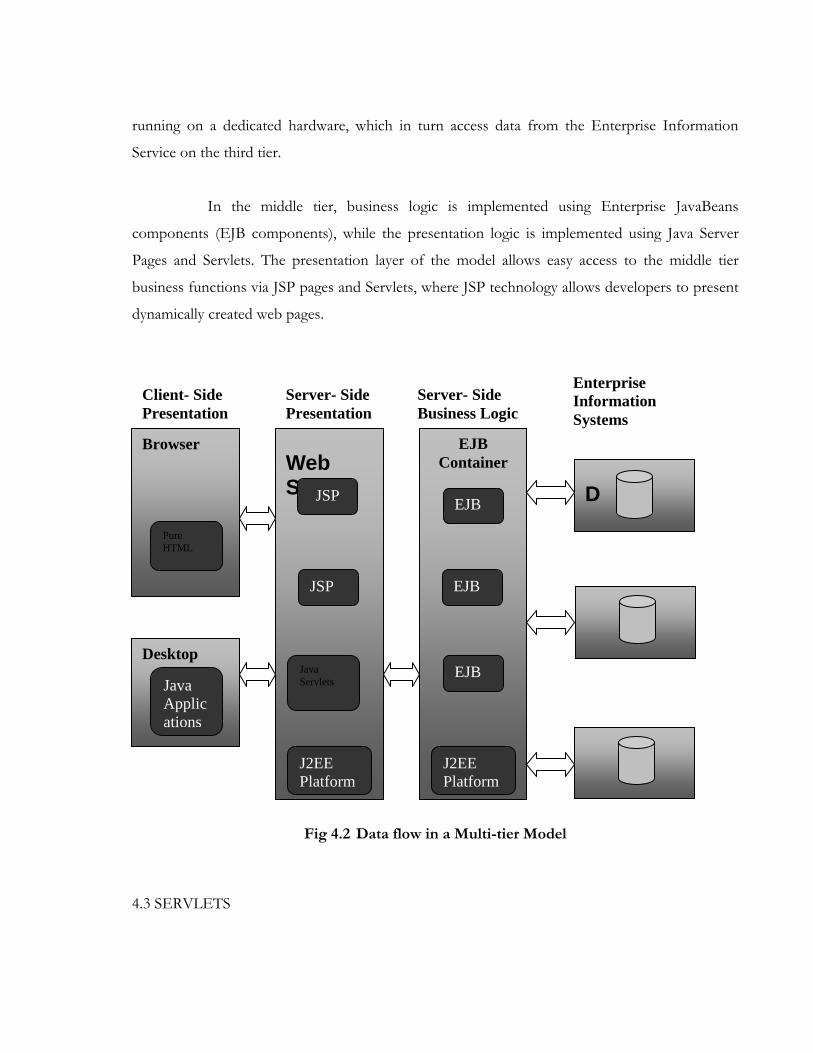
running on a dedicated hardware, which in turn access data from the Enterprise Information
Service on the third tier.
In the middle tier, business logic is implemented using Enterprise JavaBeans
components (EJB components), while the presentation logic is implemented using Java Server
Pages and Servlets. The presentation layer of the model allows easy access to the middle tier
business functions via JSP pages and Servlets, where JSP technology allows developers to present
dynamically created web pages.
Fig 4.2 Data flow in a Multi-tier Model
4.3 SERVLETS
D
Browser
Desktop
Web Server
EJB Container
Pure HTML
Java Applications
J2EE Platform
Java Servlets
EJB
JSP EJB
EJB JSP
J2EE Platform
Client- Side Presentation
Server- Side Presentation
Server- Side Business Logic
Enterprise Information Systems

Servlets run on an application server or Web server rather than in a Web browser. In
iPlanet Application Server, Servlets make up the presentation logic of an application by acting as a
central dispatcher for the application by processing form input, invoking business logic
components by accessing EJB, and formatting page output using JSP pages
4.3.1 Types of Servlets
• Generic Servlets extend javax.servlet.GenericServlet. Generic Servlets are protocol
independent, meaning that they contain no inherent support for HTTP or any other
transport protocol.
• HTTP Servlets extend javax.servlet.HttpServlet. These Servlets have built-in support
for the HTTP protocol and are much more useful in an iPlanet Application Server
environment.
For generic Servlets, you simply override the service() method to provide routines
for handling requests. HTTP Servlets provide a service method that automatically routes the
request to another method in the Servlets based on which HTTP transfer method is used, so for
HTTP Servlets you would override doPost() to process POST requests, doGet() to process
GET requests, and so on.
4.4 JAVA SERVER PAGES
Java Server Pages (JSP) are HTML pages with embedded Java based code, which
enables complex server side processing and allows conditional output and communicate with
other objects in your application.
JSP pages are compiled into Servlets, either when installed or the first time they are
called. This makes JSP pages available to the application environment as standard objects and
enables them to be called from a client using a URL.
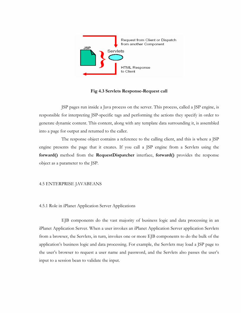
Fig 4.3 Servlets Response-Request call
JSP pages run inside a Java process on the server. This process, called a JSP engine, is
responsible for interpreting JSP-specific tags and performing the actions they specify in order to
generate dynamic content. This content, along with any template data surrounding it, is assembled
into a page for output and returned to the caller.
The response object contains a reference to the calling client, and this is where a JSP
engine presents the page that it creates. If you call a JSP engine from a Servlets using the
forward() method from the RequestDispatcher interface, forward() provides the response
object as a parameter to the JSP.
4.5 ENTERPRISE JAVABEANS
4.5.1 Role in iPlanet Application Server Applications
EJB components do the vast majority of business logic and data processing in an
iPlanet Application Server. When a user invokes an iPlanet Application Server application Servlets
from a browser, the Servlets, in turn, invokes one or more EJB components to do the bulk of the
application’s business logic and data processing. For example, the Servlets may load a JSP page to
the user’s browser to request a user name and password, and the Servlets also passes the user’s
input to a session bean to validate the input.
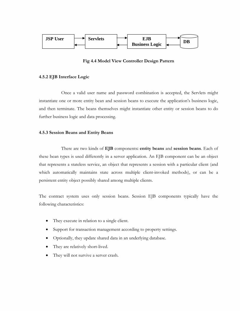
Fig 4.4 Model View Controller Design Pattern
4.5.2 EJB Interface Logic
Once a valid user name and password combination is accepted, the Servlets might
instantiate one or more entity bean and session beans to execute the application’s business logic,
and then terminate. The beans themselves might instantiate other entity or session beans to do
further business logic and data processing.
4.5.3 Session Beans and Entity Beans
There are two kinds of EJB components: entity beans and session beans. Each of
these bean types is used differently in a server application. An EJB component can be an object
that represents a stateless service, an object that represents a session with a particular client (and
which automatically maintains state across multiple client-invoked methods), or can be a
persistent entity object possibly shared among multiple clients.
The contract system uses only session beans. Session EJB components typically have the
following characteristics:
• They execute in relation to a single client.
• Support for transaction management according to property settings.
• Optionally, they update shared data in an underlying database.
• They are relatively short-lived.
• They will not survive a server crash.
JSP User Servlets EJB Business Logic DB

4.6 DATA ACCESS COMPONENTS
When business components-entity beans, session beans, and even presentation
components like Servlets and helper objects for Java Server Pages (JSP) pages --need to access a
data source, they can use the appropriate API to achieve connectivity and manipulate the data
source.
But by including the connectivity and data access code within these components
introduces a tight coupling between the components and the data source implementation. Such
code dependencies in components make it difficult to migrate the application from one type of
data source to another. When the data source changes the components need to be modified in
order to make them work with the new data source. We use a Data Access Object (DAO) to
abstract and encapsulate all access to the data source. The DAO manages the connection with the
data source to obtain and store data.
The business component that relies on the DAO uses the simpler interface exposed
by the DAO for its clients. The DAO completely hides the data source implementation details
from its clients. Because the interface exposed by the DAO to clients does not change when the
underlying data source implementation changes, this pattern allows the DAO to adapt to different
storage schemes without affecting its clients or business components.
Fig 4.5 Class Diagram for DAO pattern relationships
4.6.1 Business Objects

The Business Object represents the data client. It is the object that requires access to
the data source to obtain and store data. A Business Object may be implemented as a session
bean, entity bean, or some other Java object, in addition to a Servlets or helper bean that accesses
the data source.
4.6.2 Data Access Objects
Data Access Object is the primary object of this pattern. The Data Access Object
abstracts the underlying data access implementation for the Business Object to enable transparent
access to the data source. The Business Object also delegates data load and store operations to the
Data Access Object.
4.6.3 Data Source
This represents the source of the data. A data source could be a database such as an
RDBMS, OODBMS, XML repository, flat file system, and so forth. A data source can also be
another system (legacy/mainframe), service (B2B service or credit card bureau), or any other kind
of data repository.
CHAPTER 5
SYSTEM DESIGN - PRELIMINARY
5.1 INTRODUCTION
System design is a solution, how to approach to the creation of a system. This
important phase provides the understanding and procedural details necessary for implementing
the system recommended in the feasibility study. The design step produces a data design, user
interface design, modular design and input/output design. From a project management point of
view, software design is done in two steps – preliminary design and detailed design. Preliminary
design is concerned with the transformation of into data and software architecture. Detailed
design focuses on refinements to the architectural representation that leads to detailed data
structure and algorithmic representations of software.
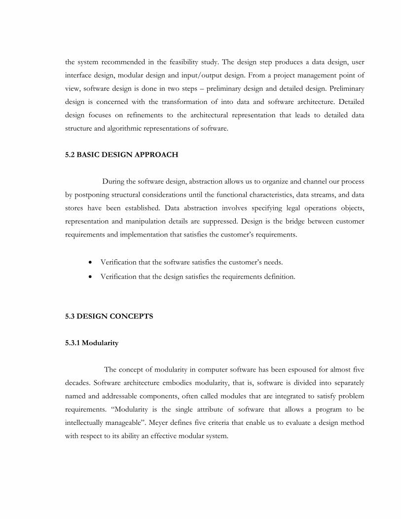
5.2 BASIC DESIGN APPROACH
During the software design, abstraction allows us to organize and channel our process
by postponing structural considerations until the functional characteristics, data streams, and data
stores have been established. Data abstraction involves specifying legal operations objects,
representation and manipulation details are suppressed. Design is the bridge between customer
requirements and implementation that satisfies the customer’s requirements.
• Verification that the software satisfies the customer’s needs.
• Verification that the design satisfies the requirements definition.
5.3 DESIGN CONCEPTS
5.3.1 Modularity
The concept of modularity in computer software has been espoused for almost five
decades. Software architecture embodies modularity, that is, software is divided into separately
named and addressable components, often called modules that are integrated to satisfy problem
requirements. “Modularity is the single attribute of software that allows a program to be
intellectually manageable”. Meyer defines five criteria that enable us to evaluate a design method
with respect to its ability an effective modular system.

• Modular decomposability: - If a design method provides a systematic mechanism for
decomposing the problem into sub-problems, it will reduce the complexity of overall
problem, thereby achieving an effective modular solution. For example job posting
module is divided in to 6 different sub modules.
• Modular composability: - If a design method enables existing design components to be
assembled into new system, it will yield a modular solution that does not reinvent the
wheel.
• Modular understandability: - If a module can be understood as a stand alone unit, it
will be easier to build and easier to change.
• Modular continuity: - If a small changes in the system requirements result in changes to
individual modules, rather than system wide changes, the impact of change-induced side
effects will be minimized.
5.3.2 Functional Independence
The concept of functional independence is the direct outgrowth of modular design
and the concepts of abstraction and information hiding. Functional independence is achieved by
developing self sufficient modules with an aversion to excessive interaction with other modules.
Since the functional independence may be compartmentalized the interface are simplified. Error
propagation may be reduced, independent modules are easier to test and maintain because
secondary effects caused are limited. Functional independence helps in making modules reusable.
5.3.3 Cohesion and Coupling
Cohesion is a natural extension of the information hiding concept described a
cohesive module performs a single task within the software procedure, requiring little interaction
with the procedure being performed in the other parts of a program. It is important to strive for

high cohesion and recognize low cohesion so that software design can be modified to achieve
greater function independence. A module that performs a set of tasks that relate to each other
loosely, if at all, is termed coincidentally cohesive.
Coupling is a measure of interconnection among modules in a program structure.
Like cohesion, coupling may be represented on a spectrum. Coupling depends on the interface
complexity between modules, the point at which entry or reference is made to a module, and what
data pass across the interface.
5.4 USER INTERFACE DESIGN
Four different models come into play when a user interface is to be designed. The
software engineer creates a design model, a human engineer establishes a user model, and the
end-user develops a mental image that is often creating system image. Unfortunately, each of
these models may differ significantly. The role of interface designer is to reconcile these
differences and derive a consistent representation of the interface.
Users of Synergy are given below:-
• Recruitment Team / Employees
• Partners / Staffing agencies
• Candidates
For each user there is different interface. A design model of the entire system
incorporates data, architectural, interface, and procedural representations of the software. The
user interface design process encompasses four distinct framework activities
• User, task and environment analysis and modeling
• Interface design
• Interface construction
5.5 DATABASE DESIGN
Oracle 8i is chosen for developing the database. For the optimum design of the
database to have better response time and data integrity, avoid data redundancy, and for security
of the database are some of the reasons behind the choice of Oracle.
5.5.1 Normalization:
• First Normal Form (1NF) - It states that the domain of an attribute must include only
atomic value and that of any attribute in a tuple must be a single value from the domain of
the attribute. Hence 1NF disallows having a set of values or a combination of both as an
attribute value for a single tuple .In other words 1NF disallows relations within relations
or relations as attribute of tuples. The only attribute values permitted by 1NF are single
atomic values. All the tables in the database satisfy the first normal form.
• Second Normal Form (2NF) - The test for 2NF involves testing for functional
dependencies whose left hand side attribute are part of the primary key. If the primary key
contains a single attribute the test need not be applied at all. A relation schema R is in
2NF if every non prime attribute A in R is functionally dependent on the primary key of
R. All the tables with two attributes in the primary key field satisfy second normal form.
For example in the jobs master table job code is the primary key.
• Third Normal Form (3NF) - A functional dependency X->Y in a relation schema R is a
transitive dependency if there is neither a set of attributes Z that is neither a candidate key
nor a subset of any key of R and both X -> Z and Z -> Y hold true.
5.6 INPUT / OUTPUT DESIGN

5.6.1 Input Design
Input Design is the process of converting the user originated inputs to a computer
based format. Input design is a part of overall system design that needs careful attention and it
includes specifying the means by which actions are to be taken. Since the inputs have to be
planned in such a manner so as to get the relevant information, extreme care is taken to obtain
the pertinent information. If the data fed into the system is incorrect, then the processing as well
as the outputs will magnify these errors .The arrangement of messages and comments in online
conversations, as well as the placement of data, headings, and titles on display screens or source
documents, is also part of the input design. Online systems include a dialogue or conversation
between the user and the system.
• Controlling the Amount of Input - The major reasons for controlling the amount of
input are, first as the cost of labor is high, the cost of preparing the data and entering the
data is also high. Second, the input phase of computing can be a slow process that can
take many times longer than the time needed by computers to carry out their tasks.
• Avoiding Bottlenecks - A processing delay results from data preparation or data entry
operations is called a bottleneck. Avoiding bottleneck should always be one objective of
the analyst in designing input.
• Avoiding Errors - The third objective deals with errors .In one sense, the rate at which
errors occur depends on the quantity of data, since the smaller the amount of data to
input. The fewer the opportunities for errors. The manner in which the data is entered
also affects the occurrence of errors. Another aspect of avoiding error is the need to
detect the error when they do occur. These are done using input validation techniques.
• Keeping the process simple - Simplicity works and it is accepted by the users. In
contrast it takes work to get users to accept complex or confusing input designs, and there
is no guarantee of success in installing a complex system.

In my module all the above discussed points are given due importance while designing the input.
It avoids delay and provides the user with necessary support to enter the data in an easy manner.
5.6.2 Output Design
Output design refers to the results and information that are generated by the system.
It is on the basis of the outputs generated that the usefulness of the application is evaluated. The
significant points that have to be considered for the output design are as follows:
• Determine what information to present.
• Decide the medium of output.
• Arrange the presentation of information in an acceptable format.
• Decide how to distribute the output to intended recipients.
The arrangement of information on a display, or a printed document is termed as a
layout. Layout forms, sheets that describe the location characteristics and the format of the
column headings and pagination. Output design phase of system is concerned with the
convergence of information to the end user in user-friendly manner.
The output design should be efficient, intelligible so that the system relationship with
the end user is improved considerably and thereby, enhancing the decision-making process. The
contents of the output are then defined in a detailed manner during the physical design of
outputs.
CHAPTER 6
SYSTEM DESIGN - DETAILED
6.1 INTRODUCTION
Detailed design deals with the various modules in detail explaining them with
appropriate description and specifying the tables referenced and updated. This will helps the
programmers to implement the internal logic for the module in the given specification. The
design specification addresses different aspects of the design model and is completed as the
designer refines the representation of software. The design specification contains a requirement
cross-reference.
In this section, I will describe the design of the modules with respect to the
Functional, Non-functional and Data Requirements as discovered in the Requirement Analysis.
The System would be developed as per the J2EE Architecture. The different modules
in the system will be developed using this Architecture. The applications will consist of Data
Access Objects, Servlets, JSPs (Java Server Pages), JavaScript, Java Beans and EJB (Enterprise
Java Beans).
Front-end screens will be developed using Java Server Pages. The Data will be stored
in the Backend using Oracle 8i.
6.2 DATABASE DESIGN
The following tables have been designed as per requirement. The table presented here
are for illustrative purposes only.
6.2.1 Table Descriptions

• EMPLOYEE_TABLE
This table would be used to capture the employee details, such as name, email, location,
etc. which would be uniquely identifiable using the employee id.
• RESUME_TABLE
This is used to capture all the details of the candidate resumes being posted, such as
candidate name, date of birth, including the jobs against which the resumes are being
posted. All the resumes in the table would be uniquely identified by the resume number.
• RESUME_HISTORY_TABLE
This table would capture the states of the resumes as they change during the processing of
candidate, or resume modification by the candidate. The sole purpose of this is tracking,
reporting, and auditing.
• RESUME_BACKUP_TABLE
This table would be used to hold the resumes of candidates who were found suitable but,
could not be offered because of filling of requirements or any other reason.
• UNFIT_RESUME_TABLE
The resumes that have been found unfit would be moved from resume_table would be
stored here for configurable amount of time.
• JOB_TABLE
All the details of the jobs created, and their statuses would be captured in this table. Each
job is uniquely identifiable by its job code.
• LOGIN_TABLE

This table would be used to capture the details of the users who can access to the system
and what are they allowed to do. Each record in this table would be uniquely identified by
the user id.
• CANDIDATE_LOGIN_TABLE
This would be used to capture the details including candidate id and password required
for providing access to the candidate desktop.
• CANDIDATE_ASSESSMENT_TABLE
This table would be used to capture the candidate assessment details, such as marks
scored in the test, technical interview and hr interview etc. Each record in this table would
be uniquely identifiable by Candidate’s Resume number.
• TEST_DETAIL_TABLE
This table would be used to capture all the details pertaining to test’s, such as location,
date, time etc. All the records would be uniquely identified by test id.
• MASTER_TABLE
This table would be used to store all the codes used throughout, such as status, location
codes, etc. All codes will be uniquely identified by Code Id.
• CONFIG_VAL_TABLE
This table would be used to store all the configurable values, which would be used
throughout for various purposes, such as number of days the resumes should be kept, etc.
All values would be uniquely identified by Value Id.
• MAIL_TXT_TABLE
This table would be used to store the content of various mails that need to be sent. All the
mails would be uniquely identified by Mail Id.

• MAIL_DISPATCH_TABLE
All the details of mails that are to be sent will be captured in this table.
All the mails sent will be uniquely referenced by Mail Number.
Apart from the tables specified above, a set of history tables were designed for some
of the above given tables to capture the change history of the records in the table, for auditing
and reporting purposes. Whenever a record is modified in the table for which history table exists,
an entry is made into the corresponding history table for that particular record.
6.2.2 Database Diagram
Fig 6.1 Database Diagram

6.3 DATA FLOW DIAGRAMS
Fig 6.2 DFD - User Login
Validated Job Details
User Id & Rights
Codes
Job Details Job Details
Employee DetailsRECRUITER
Job
Creation
EMPLOYEE_TABLE
JOB_TABLE
MASTER_TABLE
JOB_TABLE
USER SESSION
User Id, Rights
User Id, Password & Rights
User Id & Password USER
Validation&
Authentication
LOGIN_TABLE
USER SESSION

Fig 6.3 DFD - Job Creation
Fig 6.4 DFD - Test Creation
Test Details Validated Test Details
User Id & Rights
Codes
Test Details Job Details
Employee DetailsSystem Admin
Test
Creation
EMPLOYEE_TABLE
JOB_TABLE
MASTER_TABLE
TEST_DETAIL_TABLE
USER SESSION
TEST_DETAIL_TABL
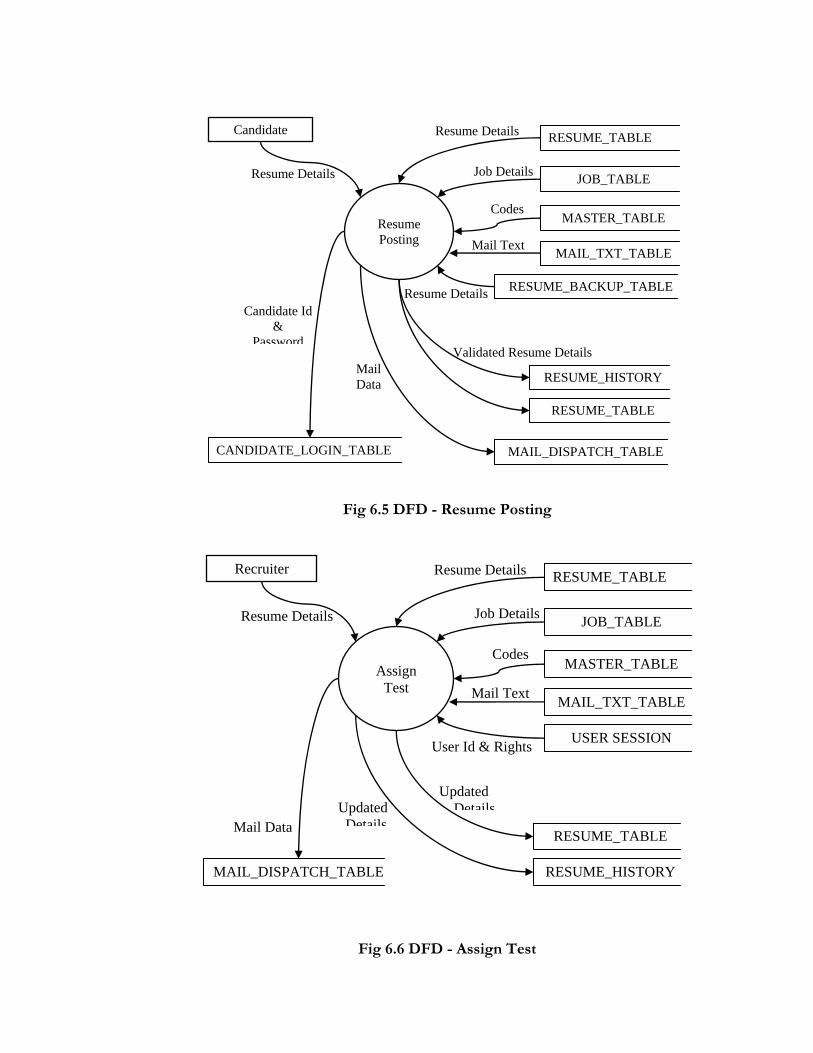
Fig 6.5 DFD - Resume Posting
Fig 6.6 DFD - Assign Test
Updated Details
User Id & Rights
Mail Data Updated
Details
Mail Text
Codes
Resume Details Job Details
Resume Details Recruiter
Assign
Test
RESUME_TABLE
JOB_TABLE
MASTER_TABLE
RESUME_HISTORY
MAIL_TXT_TABLE
MAIL_DISPATCH_TABLE
USER SESSION
RESUME_TABLE
Mail Data
Candidate Id &
Password
Resume Details
Validated Resume Details
Mail Text
Codes
Resume Details Job Details
Resume Details Candidate
Resume Posting
RESUME_TABLE
JOB_TABLE
MASTER_TABLE
RESUME_TABLE
MAIL_TXT_TABLE
CANDIDATE_LOGIN_TABLE MAIL_DISPATCH_TABLE
RESUME_BACKUP_TABLE
RESUME_HISTORY
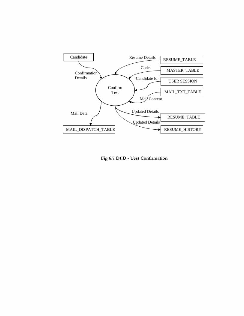
Fig 6.7 DFD - Test Confirmation
Updated Details
Updated Details
Mail Content
Candidate Id Confirmation Details
Codes
Resume Details Candidate
Confirm
Test
RESUME_TABLE
MASTER_TABLE
USER SESSION
RESUME_HISTORY
MAIL_TXT_TABLE
Mail Data
MAIL_DISPATCH_TABLE
RESUME_TABLE

Fig 6.8 DFD - Resume Processing
Updated Details
User Id & Rights
Mail Data Candidate Details
Mail Text
CodesResume Number
Resume DetailsRecruiter
SAP
Transfer
RESUME TABLE
MASTER_TABLE
SAP
MAIL TXT TABLE
MAIL DISPATCH TABLE
USER SESSION
RESUME TABLE
RESUME HISTORY
Job Details
Updated Details
User Id & Rights
Mail Data
Assessment Details
Mail Text
Codes
Resume
Resume DetailsRecruiter
Resume
Processing
RESUME TABLE
JOB TABLE
MASTER TABLE
CANDIDATE ASSESMENT TABLE
MAIL TXT TABLE
MAIL DISPATCH TABL
USER SESSION
RESUME TABLE
UNFIT RESUME TABLE
RESUME HISTORY

Fig 6.9 DFD - SAP Transfer by Recruiter
CHAPTER 7
CODING, TESTING AND IMPLEMENTATION
7.1 CODING
Coding converts the design model into executable domain. Coding is not just
translation of design in to code but also translation of design into efficient, easily understandable
and elegant code. A server side programming along with client side scripting language is used to
establish the various data and control flows.
The following make Synergy modular and easy to extend or improved:-
• Naming Conventions - Naming conventions were followed to increase the readability
and understandability of the code. The following conventions were followed to name the
programs, methods, variables etc.
o General - The name chosen should be appropriate and meaningful, so as to make
it easy for the developer to identify the purpose of the program, variable or
function.
o Programs - Each program name should start with the first letter in uppercase of
the subsystem they belong to. Example for posting the job details the sub system
was named as Jobposting.java.
o Variable Names - The first letter of the variable name is always lowercase. For
example: in a server side program, which validates the password got from the

client, the password from the client is retrieved from the request and stored in a
variable named spassword, s standing for server. Multi-word identifiers are
internally capitalized for clarity.
o Methods - The first letter of a method is always lower case. The remaining are the
same as for variables.
• Comments - Comments play a very important role in making the code readable and
understandable. Comments should be used wherever necessary, though overuse of
comments should be avoided. It can provide a clear guide for the last phase of software
development called maintenance.
Hence precise comments are provided in the following places:-
1. When a variable is used first.
2. When a method is declared.
3. In the beginning of each program.
4. Wherever complex logic is involved.
• Statement Construction And Indentation - Proper construction of statements and
indentation are necessary to overcome ambiguity. Two blank lines with proper comments
separate the different functional blocks.
The following are some of the indentation rules followed:-
1. Using parentheses to clarify expressions.
2. Using spacing for readability of symbols.
3. Avoiding heavy nesting of loops and conditions.
7.2 TESTING

Testing of software extends throughout the coding phase and it represents the ultimate review of specification, design and coding. A series of test cases are created with an intention of testing the software. Based on the way the software reacts to these tests, one can decide whether the product that has been built is robust or not. Test cases play a vital role in directing test engineers towards their goal. Testing activity is performed by employees within the project team excluding the developers.
The tester has to checks for all possible inputs and outputs and find out any errors
and report it to the Test Leader. The Test Leader asks the developer to fix the errors reported by
the tester. The errors are reported to the Test Leader are with respect to the test cases given to
the tester. The tester has to prepare error log comments table for each test case where the error is
present.
7.2.1 Unit Testing
Each of the modules developed were tested independently. The following were
considered during the unit test:-
• The module interface is tested to ensure that information properly flows in and out of the
unit under test.
• The local data structure is examined to ensure that data stored temporarily maintains
integrity throughout the unit’s lifetime.
• Boundary conditions are tested.
• All independent paths through the control structure are exercised to ensure that all
statements in the module have been executed at least once.
• All Error handling paths are tested.
7.2.3 Integration Testing

Integration testing was done to verify the coexistence of all the modules and the
forms involved. Bottom-Up integration testing strategy was used for this purpose. After unit
testing of each of the modules, they are integrated from the bottom by combining each of the
units into clusters.
Within a module, the sub modules were loosely coupled. Hence integrating within
a sub system was not a problem. So integration testing was focused on those modules, which
were tightly coupled. After a full-fledged integration of all the modules to the homepage, the
site was tested for interface errors, connection errors etc., and was corrected to work
successfully.
7.2.4 Validation Testing
It is said that validation is successful when the software functions in a manner that
can be reasonably expected by the customer. This type of testing is very important, because it is
the only way to check whether the requirements given by the user have been completely fulfilled.
Each and every sub module was tested whether it provided the required functionality. Each input
field was tested with the validation rules specified for them.
7.2.5 Acceptance Testing
This testing was performed to check whether the developed site met all its requirements. It is a kind of validation. Hence the site was launched for a minimal set of employees and the interfacing errors found were corrected. Reasonable expectations defined in the SRS and any new changes expected were achieved.
7.2 IMPLEMENTATION

The following are the primary issues that are encountered:-
• A separate Test Server is needed for testing, because addition and modification of Servlets
and EJB require a build, which requires server restarts.
• A separate dummy database is needed for testing purpose because in data in live database
cannot be risked.
• Browser incompatibility was a major problem for achieving constant look and feel and
functionality, across browsers.
7.3 INTEGRATION ISSUES
The integration of newly developed system into an existing system poses a lot of
challenges, especially in cases of large system having a lot of complexity, because it’s possible that functionality which works fine in separate systems may not work, or worse if the integration process breaks the existing functionality in some unknown way. The integration of different units in to the system involves lots of testing on the tester’s part. The integration of a system of reasonably large size easily leads to problem areas. Finding problem areas and solving it, is a challenge.
CHAPTER 8
CONCLUSION AND FORESEEABLE ENHANCEMENTS
8.1 CONCLUSION
The success or failure of any project is ultimately decided by the users of the system,
no matter how good or efficient a system is, if it fails to meet the expectation of the users it is a
failure. Thus the goal of any system apart from other requirements is to meet or exceed the user’s
expectation.

Great care has been taken to satisfy the expectation of different users by providing a
user-friendly system so that it enables the end users to get things done easily and efficiently, the
system is configurable to great extent to allow for the customisation and fine tuning by System
administrators, the system was developed with extensibility in mind so that future requirements
can be easily incorporated by software developers. The selection of software is the building block
for the development of the system. The choice of J2EE design patterns were chosen after
carefully studying the system.
The project deals with the various recruitment activities of Wipro Technologies. The
objective of the project is determined in the manner in which the recruitment activities are
effortlessly carried out with increased efficiency and throughput. In this system best efforts have
been made to overcome the difficulties faced by the existing system. Data retrieval is made faster
and flexible search options have also been provided.
Working on this live project has been a learning experience. There was a lot of
positive feedback when the final testing of the project was over. This software is designed to
provide fast, reliable and secure access to the end-users. There are several features that can be
added and the application can be improved. Every effort has been taken to develop a well
approved system.
8.2 FORESEEABLE ENHANCEMENTS
The e-Recruitment System surely has further scope for development based on the
forthcoming requirements and the deployment of logical analysis in the development thereafter.
Given below are few of the enhancements that can be incorporated:-
• Access to Synergy via Mobile Devices (e.g. by WAP).
• Candidates can get status updates and alerts via SMS, or post resume against a new job
code via SMS.
• The test taken by candidate can be made online and integrated into ‘Synergy’. The test
scores of the candidate can then be automatically uploaded and eligible candidates can be
automatically scheduled for interview.
• A module can be developed that will allow resume search and upload from multiple
databases from different vendors.
• Context sensitive / Balloon help can be included throughout ‘Synergy’ giving tips and
examples to make it easier for novice users to use the system.
• An Error Reporting module that will take over in case of any error, and would provide
with valuable details regarding the cause of error, what was being done when error
occurred, and if possible suggest a solution.
• Advanced user query for job search, and facility to auto post resumes against jobs based
on user criteria, while informing the same to the candidate.
APPENDIX 1
SELECTED SCREEN SHOTS

Fig A 1.1 Job Create Screen

Fig A 1.2 Test Create Screen
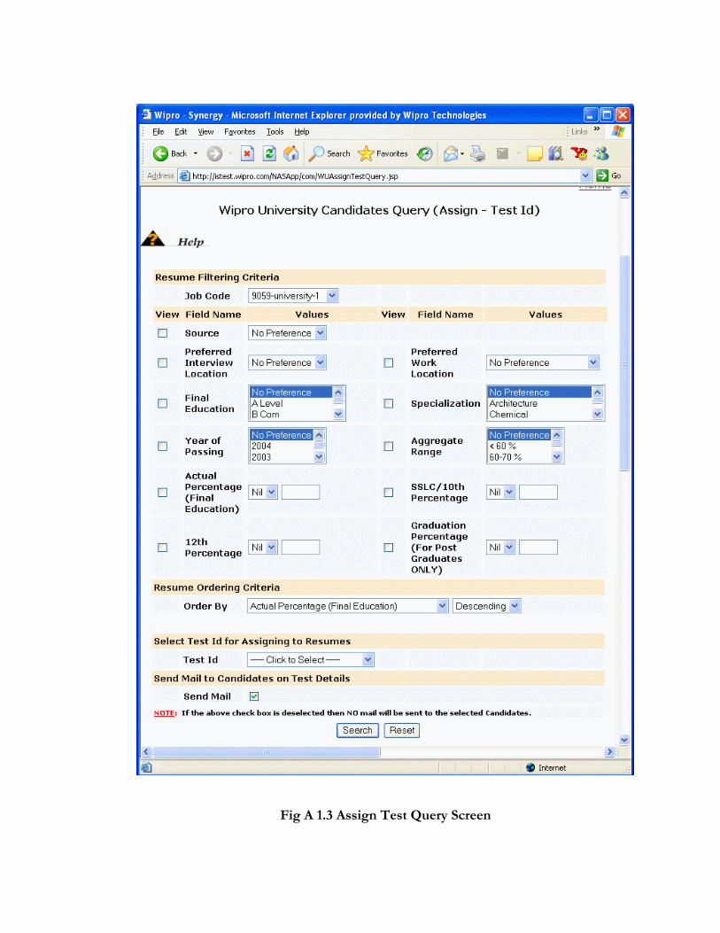
Fig A 1.3 Assign Test Query Screen

Fig A 1.4 Assign Test Screen


Fig A 1.5 Query Screen – Process Candidates
Fig A 1.6 Process Candidate Screen (in part)

Fig A 1.7 Process Candidate Screen (contd.)

Fig A 1.8 SAP Transfer Screen
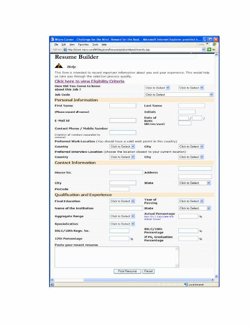
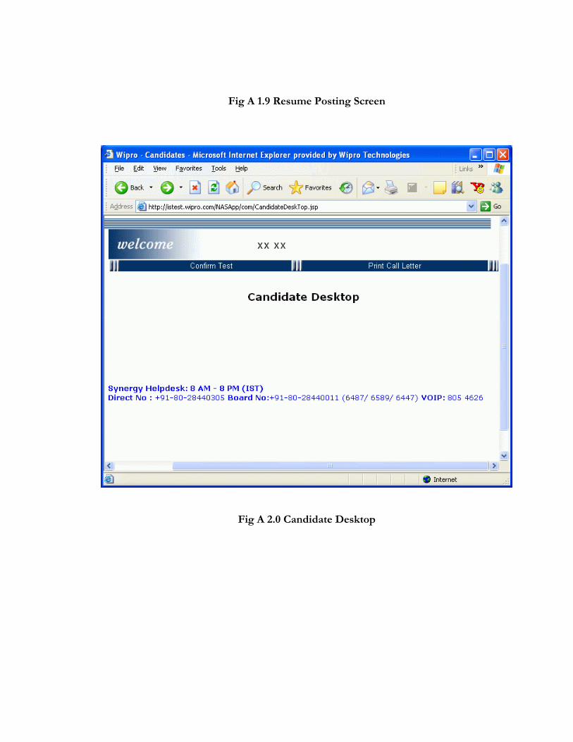
Fig A 1.9 Resume Posting Screen
Fig A 2.0 Candidate Desktop

REFERENCES
BOOKS
1. Bruce Eckel, “Thinking in Java”, 3rd edition. 2. Dan Malks, “Professional JSP”, Wrox Publications, Wrox Press, 2000. 3. Marty Hall, “Core Servlets and Java Server Pages”, Prentice Hall, 2000. 4. O'Reilly, “Java-Script”, O'Reilly & Associates, Inc, 2000-2003 5. Paul Perrone, Venkata S.R. "Krishna" R. Chaganti, Tom Schwenk,”J2EE Developer's
Handbook”, Sams, 2003
6. Roger S.Pressman, “Software Engineering: A Practitioner Approach”, 5th Edition, McGraw Hill, 1999.
WEBSITES
1. http://isd.wipro.com 2. http://java.sun.com
3. http://knet.wipro.com 4. http://www.codeguru.com
5. http://www.javaworld.com 6. http://www.sourceforge.net