Embed Size (px)
Citation preview
Schaeffl er SYMPOSIUM 2010
26 Chassis
344 Schaeffl er SYMPOSIUM 2010 345
26Chassis
26
26 Chassis
345Schaeffl er SYMPOSIUM 2010Schaeffl er SYMPOSIUM 2010344
Chassis systemsSchaeffl er is more than just bearings
Manfred Kraus
Schaeffl er SYMPOSIUM 2010
26 Chassis
346 Schaeffl er SYMPOSIUM 2010 347
26Chassis
26
Introducti onThe launch of ABS in the 1970s marked the starting point for the introduction of electronic control systems in chassis. In the following years, driving dynamics control systems were used to an increasing extent in passenger cars, with longitudinal, vertical and lateral dynamic driving characteristics can be improved. Fur-ther potential resulted from the ever increasing networking of functions [3]. This further devel-opment of the on-board power supply is cur-rently setting prerequisites for further driving dynamics systems with electromechanical ac-tuators.
Some of these systems – such as the superim-posed steering system – owe their existence and full functionality to increasing, further develop-ment of electromechanical systems and micro-processor technology. Other systems have hy-dromechanical predecessors such as electric power steering (EPS), rear wheel steering and torque vectoring (distribution of the driving forc-es to the driven axle using an electromechanical actuator). The expansion of the functions of these systems, however, was only possible with further development of microprocessor technol-ogy. For example, the parking assist system of an EPS with hydraulic steering can only be produced at significantly higher cost. In addition, the en-ergy consumption of hydraulic actuators in chas-sis is much higher than that of electromechani-cal actuators, which only consume energy when required.
The following objecti ves can be derived for chassis systems from the above.
The replacement of hydraulic actuatorsThe objective is to reduce the power consump-tion and improve existing functions, such as in steering systems. EPS has already achieved high market penetration here and is established on the market.
There has been similar development in the case of hydraulically actuated roll stabilizati on systems which will soon be replaced by electromechanical systems. It is possible that hydraulic base point dis-placement of the wheel suspension (so-called ac-
ti ve body control ABC) will be replaced by an elec-tromechanical variant.
Rear axle steering, which was offered on the Eu-ropean market as a hydraulic variant in the 1980s and 1990s, is currently experiencing a re-naissance. However, the new systems have elec-tromechanical actuators, are more economical, have more favorable fuel consumption and are easier to integrate.
Development of new functi onsThe superimposed steering system can only be manufactured on an industrial scale using an electromechanical actuator. It made it possible to superimpose the steering angle components calculated by a driving dynamics controller on the driver’s steering input, without having to disconnect the mechanical connection between the steering wheel and the front wheels, as would be required by pure, by-wire systems. In the area of vertical dynamics, a mention must be made of controlled damper settings, which not only enable adjustment in accordance with the loads and driving style, but which also con-tain more or less developed “sky-hook” compo-nents in the damper algorithms used.
Linking of systemsThe combination of superimposed steering with ESP enables the frequency and level of stabiliz-ing braking interventions to be significantly re-duced. The combination of superimposed steer-ing with rear wheel steering, on the other hand, results in a significant increase in the cornering performance at low speeds, while at the same time increasing the agility and stability in the medium and high-speed range. Similar lateral dynamic results must be achieved with the com-bination of superimposed steering and torque vectoring. Traction can be improved with torque vectoring and is comparable with a controlled locking differential.
If steering and braking systems are linked with environment detection systems with GPS and car-to-car communication, it will open up new possibilities which could lead to adaptive cruise control and a lane-keeping assistant and, in fu-ture, collision mitigation and avoidance or even autonomous driving.
Schaeffl er – more than a wheel bearingSchaeffler had already started development of mechanical actuators (ball screw drive, small planetary gear and cylindrical gear units and the bearing support for the entire module) for elec-tromechanical brakes in the 1990s. Mechanical modules for EPS were developed based on these actuators, comprising the ball screw drive in-cluding the toothed rack and bearing supports, which have been on the market since 2007 and whose manufacturing quantities continuously increase.
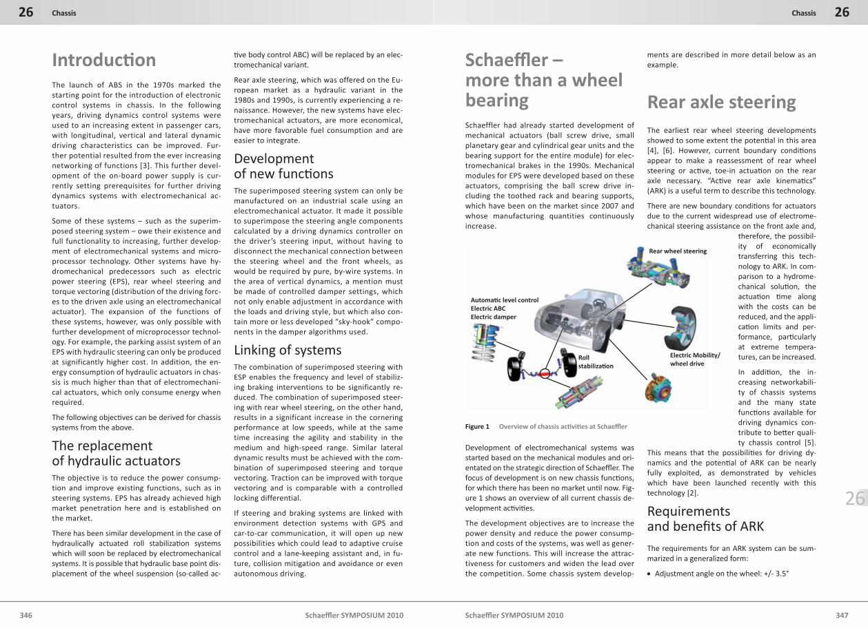
Development of electromechanical systems was started based on the mechanical modules and ori-entated on the strategic directi on of Schaeffl er. The focus of development is on new chassis functi ons, for which there has been no market unti l now. Fig-ure 1 shows an overview of all current chassis de-velopment acti viti es.
The development objectives are to increase the power density and reduce the power consump-tion and costs of the systems, was well as gener-ate new functions. This will increase the attrac-tiveness for customers and widen the lead over the competition. Some chassis system develop-
ments are described in more detail below as an example.
Rear axle steeringThe earliest rear wheel steering developments showed to some extent the potenti al in this area [4], [6]. However, current boundary conditi ons appear to make a reassessment of rear wheel steering or acti ve, toe-in actuati on on the rear axle necessary. “Acti ve rear axle kinemati cs” (ARK) is a useful term to describe this technology.
There are new boundary conditi ons for actuators due to the current widespread use of electrome-chanical steering assistance on the front axle and,
therefore, the possibil-ity of economically transferring this tech-nology to ARK. In com-parison to a hydrome-chanical soluti on, the actuati on ti me along with the costs can be reduced, and the appli-cati on limits and per-formance, parti cularly at extreme tempera-tures, can be increased.
In additi on, the in-creasing networkabili-ty of chassis systems and the many state functi ons available for driving dynamics con-tribute to bett er quali-ty chassis control [5].
This means that the possibiliti es for driving dy-namics and the potenti al of ARK can be nearly fully exploited, as demonstrated by vehicles which have been launched recently with this technology [2].
Requirements and benefi ts of ARKThe requirements for an ARK system can be sum-marized in a generalized form:
Adjustment angle on the wheel: +/- 3.5°
Rear wheel steering
Electric Mobility/wheel drive
Rollstabiliza�on
Automa�c level controlElectric ABCElectric damper
Figure 1 Overview of chassis acti viti es at Schaeffl er
Schaeffl er SYMPOSIUM 2010
26 Chassis
348 Schaeffl er SYMPOSIUM 2010 349
26Chassis
26
Adjustment distance on the actuator = 10 to 25 mm (depending on the axle)
Max. actuati on speed up to 100 mm/sec for 50 % of the full stroke
Positi oning/resoluti on: < 0.1 mm
Actuati on force up to approx. 6 kN, stati c overload up to 30 kN
Higher electromechanical effi ciency (max. batt ery current < 40 A with a 12 V on-board power supply)
Minimal energy consumpti on with a constant wheel angle
Fail-safe behavior by holding the positi on in case of a defect
The features of the actuator can be adapted to the specific requirements of the OEM if re-quired.
The following advantages of the system can be fully used if the named requirements are fulfi lled:
Opti mizati on of the ti me profi le of transverse accelerati on and yaw rate for the vehicle under transient driving conditi ons
More direct response to steering commands
Reduced inclinati on to overshoot (rear of the vehicle breaks away)
Increased safety and stability, parti cularly during braking in curves under μ-split conditi ons
Potenti al for improving the directi onal stability by reducing the structural, kinemati c, toe-in change of the rear axle
Optimized stability during trailer oper-ation
Reduced turning cycle
Reduced ti re wear and fuel consumpti on due to the possibility of reducing the initi al toe-in
There are many refer-ences to tests avail-able which quantify the advantages. The improved response
behavior and increased stability are, for exam-ple, recorded and measured by means of the 18 m slalom and the ISO lane changing test. ARK enables higher, drive-through speeds dur-ing these driving maneuvers, as proved in dif-ferent tests [1], [9]. These tests can also be used as an argument for improved trailer oper-ation. The reduction in the turning circle can be read from the Ackermann equation by making a simple adjustment. It can be also be shown that the stated pivot range of +/- 3.5° of an ARK sys-tem is sufficient to achieve a significant reduc-tion in the turning circle [1].
Actuator design for ARKThe basic actuator configuration comprises the components shown such as the electric motor with the power electronics system, sensor and ball screw drive as the gearing or mechanical ac-tuation element.
The gearing is generally designed to be self-lock-ing so that no retaining forces/currents are re-quired in a static condition and the actuator does not change its position when no current is flowing, as in the case of a possible malfunction. However, because self-locking is coupled with low efficiency, this leads to a significant power consumption during actuation. An actuator with optimized efficiency has a lower power con-sumption and improved dynamics, but in the presence of static loads, high retaining forces/currents are required to hold a position which has been reached.
Schaeffler has succeeded in improving the ener-gy consumption of the actuators. This improve-ment has been achieved by combining the effi-ciency-optimized actuator gearing (ball screw drive) with a locking mechanism, which “locks” the actuator under load in the position it has reached. This solves the problem of the conflict between the objectives, high efficiency and self-locking.
Figure 2 shows the design of such an actuator for linear motion. In addition to the electric motor and a low-friction ball-screw drive for converting rotary motion into translatory mo-tion, a freewheel which can be switched in ei-ther direction is integrated in the power flow of the actuator.
An analogy with an electrical diode is helpful in clarifying the function of the locking mechanism, whereby the comparison is only intended as an aid to understanding the concept due to the dif-ferences that exist. As a simplification, you can say that the energy which is brought into the ac-tuator from the inside outwards – i.e. induced by the motor – reaches “the outside” where it is available for actuation. However, if external forc-es are acting on the actuator, then the actuator is locked mechanically by the switchable free-wheel. The motor is relieved of stress and is thus protected from high and unnecessary electrical power consumption. At the same time, this me-chanical design also meets the fail-safe require-ment and holds the actuator in position if power is lost. A separate, electromagnetically operated locking device is not required.
The electric motor can be designed with archi-tecture which is coaxial or parallel to the axle, depending on the design space available or to meet other boundary conditions.
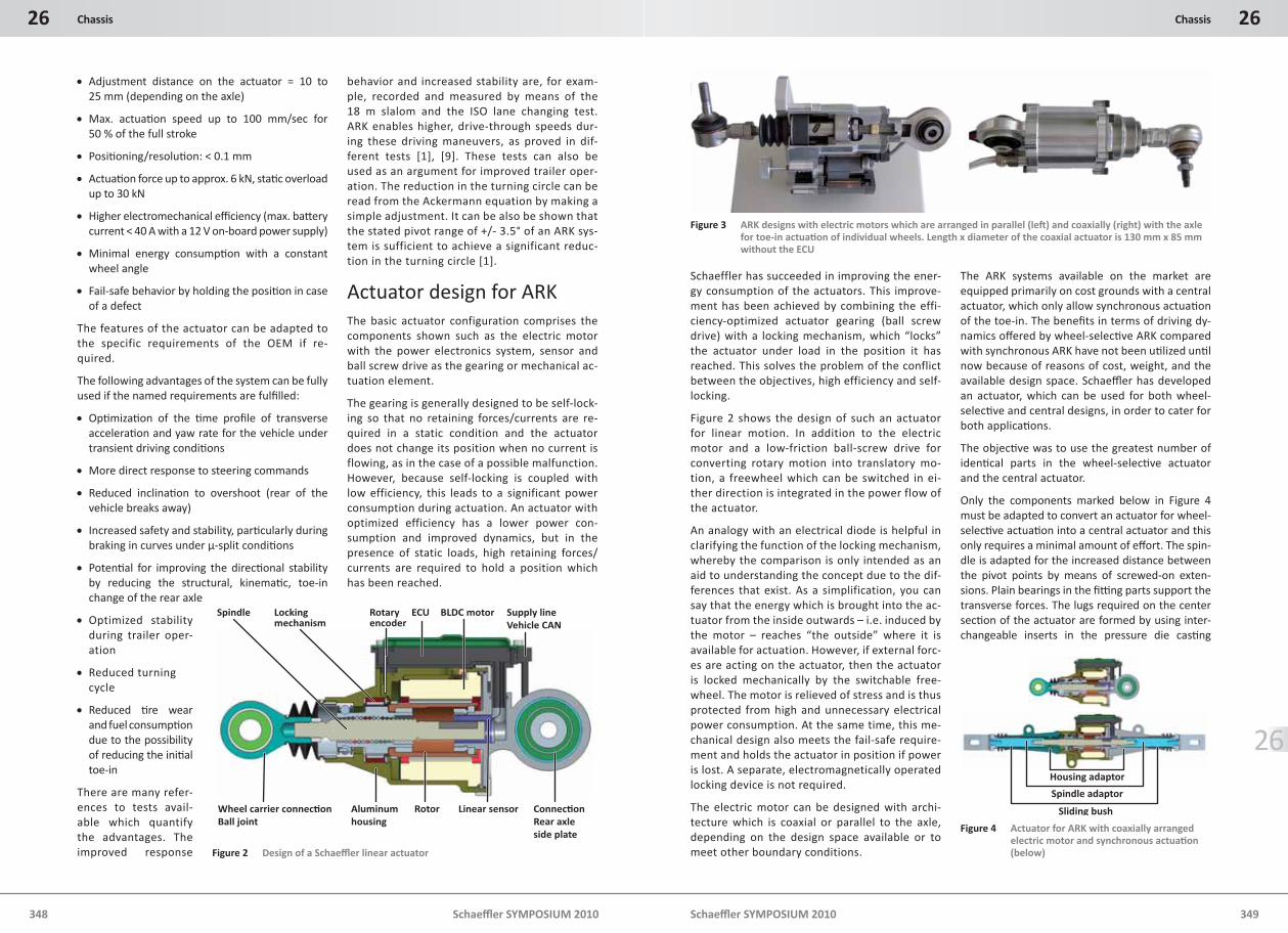
The ARK systems available on the market are equipped primarily on cost grounds with a central actuator, which only allow synchronous actuati on of the toe-in. The benefi ts in terms of driving dy-namics off ered by wheel-selecti ve ARK compared with synchronous ARK have not been uti lized unti l now because of reasons of cost, weight, and the available design space. Schaeffl er has developed an actuator, which can be used for both wheel-selecti ve and central designs, in order to cater for both applicati ons.
The objecti ve was to use the greatest number of identi cal parts in the wheel-selecti ve actuator and the central actuator.
Only the components marked below in Figure 4 must be adapted to convert an actuator for wheel-selecti ve actuati on into a central actuator and this only requires a minimal amount of eff ort. The spin-dle is adapted for the increased distance between the pivot points by means of screwed-on exten-sions. Plain bearings in the fi tti ng parts support the transverse forces. The lugs required on the center secti on of the actuator are formed by using inter-changeable inserts in the pressure die casti ng
Locking mechanism
Rotary encoder
Spindle ECU BLDC motor Supply lineVehicle CAN
Linear sensor Connec�on Rear axle side plate
RotorAluminumhousing
Wheel carrier connec�onBall joint
Figure 2 Design of a Schaeffl er linear actuator
Spindle adaptor
Housing adaptor
Sliding bush
Figure 4 Actuator for ARK with coaxially arranged electric motor and synchronous actuati on (below)
Figure 3 ARK designs with electric motors which are arranged in parallel (left ) and coaxially (right) with the axle for toe-in actuati on of individual wheels. Length x diameter of the coaxial actuator is 130 mm x 85 mm without the ECU
Schaeffl er SYMPOSIUM 2010
26 Chassis
350 Schaeffl er SYMPOSIUM 2010 351
26Chassis
26
mold. This ensures that the wheel-selecti ve actua-tor can be used without any modifi cati ons and any adapti on costs for bridging greater distances be-tween the ti e rod joints are minimized.
The design selected for the engine and the trans-mission enables the performance range shown in Figure 5 to be covered.
As a result of the high effi ciency, the maximum loading on the on-board power supply of the 12 V design is under 30 A for almost all actuati ng forces and speeds which are required by OEMs.
The Schaeffl er ARK sys-tem is off ered as a smart actuator with in-tegrated power elec-tronics to reduce the infl uence of EMC and to meet the require-ment that diff erent electromechanical sys-tems are compati ble. When deciding on this confi gurati on, great im-portance was placed on making the actuator as compact as possible and cost-eff ecti vely adapti ng a control unit from an existi ng EPS applicati on.
The usual sector process chain for driving dynamics systems, consisti ng of Matlab/Simulik, Target Link and Autobox, is used for developing the functi ons of the ARK system which are relevant to safety.
System performance and resultsAlongside testi ng on test stands, vehicle tests were conducted with Schaeffl er’s own demonstrati on vehicle to verify the performance of the ARK. Fig-ure 7 shows the fi tti ng locati on of the actuators. The functi on, strength and reliability of the me-chanical components, the electrical and electronic components and the system have been verifi ed in many endurance tests, proof tests and road tests.
Some of the test results are presented below.
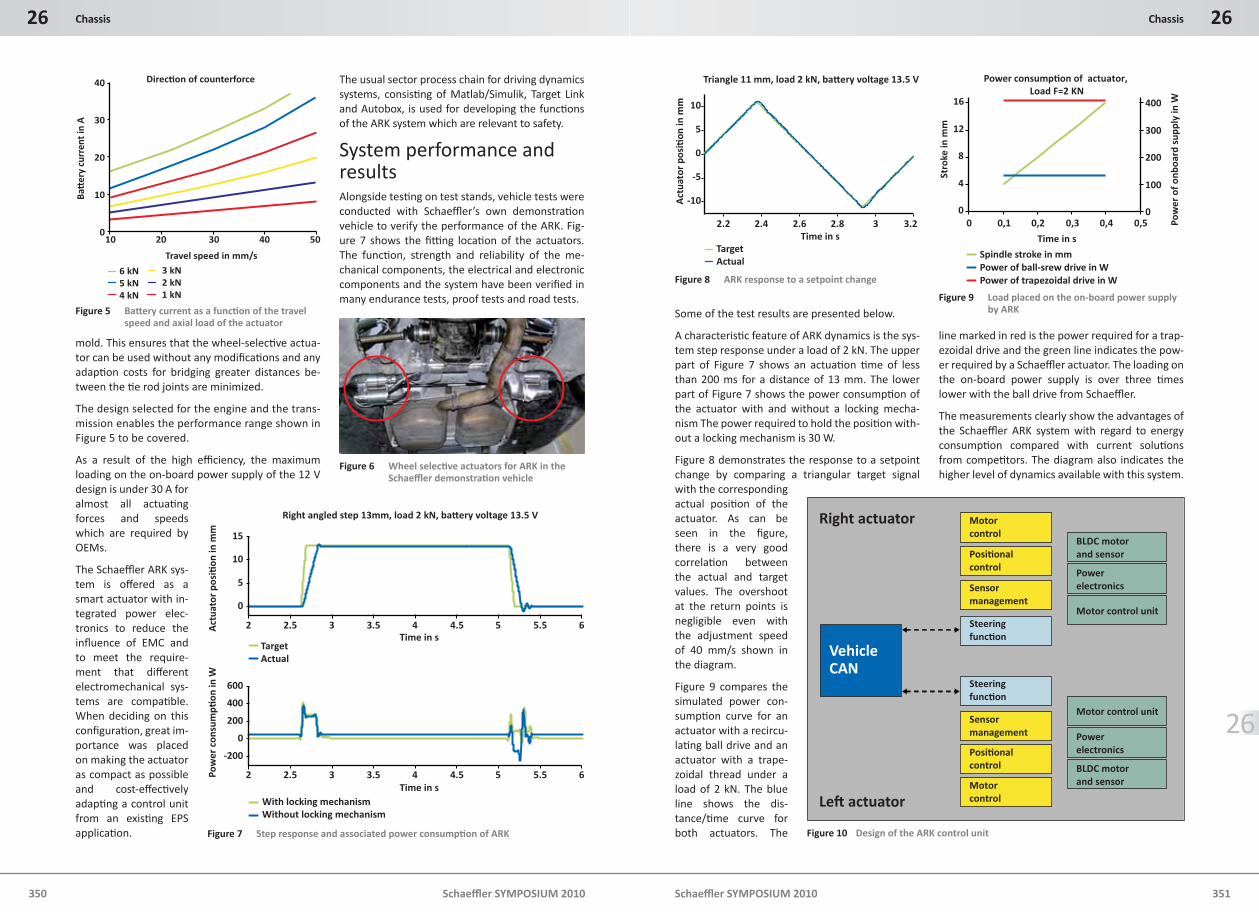
A characteristi c feature of ARK dynamics is the sys-tem step response under a load of 2 kN. The upper part of Figure 7 shows an actuati on ti me of less than 200 ms for a distance of 13 mm. The lower part of Figure 7 shows the power consumpti on of the actuator with and without a locking mecha-nism The power required to hold the positi on with-out a locking mechanism is 30 W.
Figure 8 demonstrates the response to a setpoint change by comparing a triangular target signal with the corresponding actual positi on of the actuator. As can be seen in the fi gure, there is a very good correlati on between the actual and target values. The overshoot at the return points is negligible even with the adjustment speed of 40 mm/s shown in the diagram.
Figure 9 compares the simulated power con-sumpti on curve for an actuator with a recircu-lati ng ball drive and an actuator with a trape-zoidal thread under a load of 2 kN. The blue line shows the dis-tance/ti me curve for both actuators. The
line marked in red is the power required for a trap-ezoidal drive and the green line indicates the pow-er required by a Schaeffl er actuator. The loading on the on-board power supply is over three ti mes lower with the ball drive from Schaeffl er.
The measurements clearly show the advantages of the Schaeffl er ARK system with regard to energy consumpti on compared with current soluti ons from competi tors. The diagram also indicates the higher level of dynamics available with this system.
2 2.5 3 3.5 4 4.5 5 5.5 6
0
5
10
15
Act
uato
r po
si�
on in
mm
Right angled step 13mm, load 2 kN, ba�ery voltage 13.5 V
2 2.5 3 3.5 4 4.5 5 5.5 6
-200
0
200
400
600
Time in s
Time in s
Pow
er c
onsu
mp�
on in
W
TargetActual
With locking mechanismWithout locking mechanism
Figure 7 Step response and associated power consumpti on of ARK
6 kN5 kN4 kN
10 20 30 40 50
40
30
20
10
0
Travel speed in mm/s
Ba�
ery
curr
ent i
n A
Direc�on of counterforce
3 kN2 kN1 kN
Figure 5 Batt ery current as a functi on of the travel speed and axial load of the actuator
Figure 6 Wheel selecti ve actuators for ARK in the Schaeffl er demonstrati on vehicle
2.2 2.4 2.6 2.8 3 3.2
-10
-5
0
5
10
Time in s
Act
uato
r po
si�
on in
mm
Triangle 11 mm, load 2 kN, ba�ery voltage 13.5 V
TargetActual
Figure 8 ARK response to a setpoint change
Power consump�on of actuator, Load F=2 KN
0
4
8
12
16
0 0,1 0,2 0,3 0,4 0,5
Time in s
Stro
ke in
mm
0
100
200
300
400
Pow
er o
f onb
oard
sup
ply
in W
Spindle stroke in mmPower of ball-srew drive in WPower of trapezoidal drive in W
Figure 9 Load placed on the on-board power supply by ARK
Motorcontrol
Posi�onalcontrol
Sensor management
Steeringfunc�on
Powerelectronics
Motor control unit
Right actuator
Le� actuator
BLDC motorand sensor
VehicleCAN
Steeringfunc�on
Sensor management
Posi�onalcontrol
Motorcontrol
Motor control unit
Powerelectronics
BLDC motorand sensor
Figure 10 Design of the ARK control unit
Schaeffl er SYMPOSIUM 2010
26 Chassis
352 Schaeffl er SYMPOSIUM 2010 353
26Chassis
26
The development of an add-on control unit for vol-ume producti on is a further focus of rear axle steering development. Figure 10 shows the con-cept being pursued by Schaeffl er for integrati ng the control unit arrangement in the OEM vehicle architecture.
The low-level software is applied to the Schaef-fler control unit and specially matched to the BLDC motor developed by Schaeffler. For the high-level software of the vehicle controller, the customer can use both his/her own software and the vehicle controller developed by Schaef-fler. This can be easily parameterized via a user interface and, therefore, quickly adapted to dif-ferent customer requirements. The high-level software can be applied to the Schaeffler control unit and also to an existing customer control unit if suitable.
Roll stabilizati onPassive stabilizers, usually in the form of torsion bar springs, are used to reduce sideways tilting of the body. These should not be selected with a high torsional rigidity because this will, oth-erwise, lead to a strong vertical move-ment of the body, so-called “duplicating”, when a vehicle is driv-ing over obstacles (in-terference) on one side.
To solve this conflict and also further re-duce the roll angle, hydraulically actuat-ed pivot actuators are used nowadays which twist a divided tor-sion bar depending on the transverse ac-celeration when a ve-hicle is travelling round bends, and thus noticeably re-duce the tilting of the body and significantly
equalize the wheel contact forces (Figure 11). When a vehicle is travelling straight ahead in the presence of interference on one side, the stabilizer must have an “open” effect which represents a gain in comfort in comparison with a passive stabilizer. Alternatively, tilting of the body can also be prevented by hydraulically ad-justable suspension struts on the individual wheels (active body control ABC), which can eliminate the pitching movement when braking and accelerating in addition to the roll move-ment. Pneumatic systems are not suitable for this because of the high compressibility of the air.
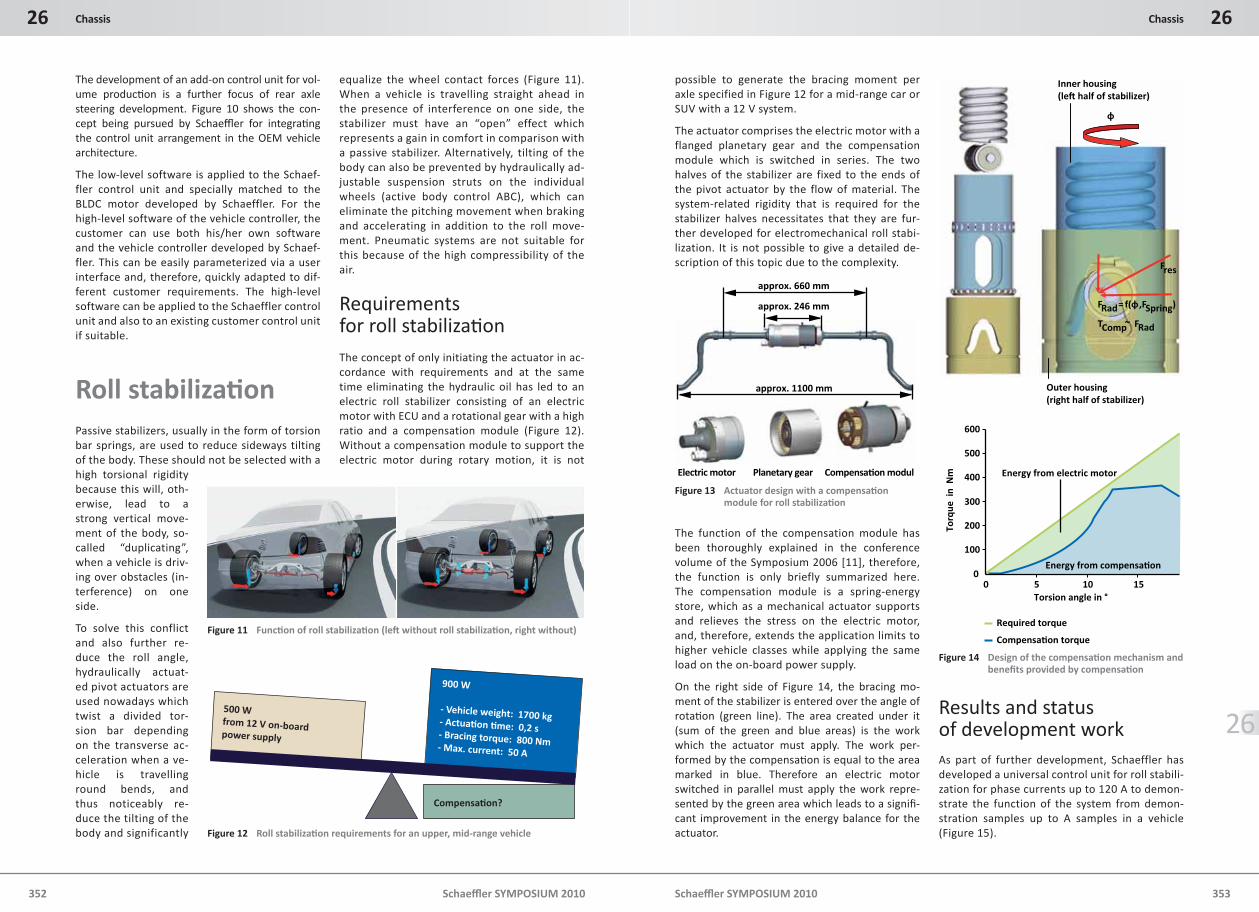
Requirements for roll stabilizati onThe concept of only initiating the actuator in ac-cordance with requirements and at the same time eliminating the hydraulic oil has led to an electric roll stabilizer consisting of an electric motor with ECU and a rotational gear with a high ratio and a compensation module (Figure 12). Without a compensation module to support the electric motor during rotary motion, it is not
possible to generate the bracing moment per axle specified in Figure 12 for a mid-range car or SUV with a 12 V system.
The actuator comprises the electric motor with a flanged planetary gear and the compensation module which is switched in series. The two halves of the stabilizer are fixed to the ends of the pivot actuator by the flow of material. The system-related rigidity that is required for the stabilizer halves necessitates that they are fur-ther developed for electromechanical roll stabi-lization. It is not possible to give a detailed de-scription of this topic due to the complexity.
The function of the compensation module has been thoroughly explained in the conference volume of the Symposium 2006 [11], therefore, the function is only briefly summarized here. The compensation module is a spring-energy store, which as a mechanical actuator supports and relieves the stress on the electric motor, and, therefore, extends the application limits to higher vehicle classes while applying the same load on the on-board power supply.
On the right side of Figure 14, the bracing mo-ment of the stabilizer is entered over the angle of rotati on (green line). The area created under it (sum of the green and blue areas) is the work which the actuator must apply. The work per-formed by the compensati on is equal to the area marked in blue. Therefore an electric motor switched in parallel must apply the work repre-sented by the green area which leads to a signifi -cant improvement in the energy balance for the actuator.
Results and status of development workAs part of further development, Schaeffler has developed a universal control unit for roll stabili-zation for phase currents up to 120 A to demon-strate the function of the system from demon-stration samples up to A samples in a vehicle (Figure 15).
Figure 11 Functi on of roll stabilizati on (left without roll stabilizati on, right without)
approx. 246 mm
approx. 660 mm
approx. 1100 mm
Electric motor Planetary gear Compensa�on modul
Figure 13 Actuator design with a compensati on module for roll stabilizati on
500 Wfrom 12 V on-board power supply
900 W
- Vehicle weight: 1700 kg- Actua�on �me: 0,2 s- Bracing torque: 800 Nm- Max. current: 50 A
Compensa�on?
Figure 12 Roll stabilizati on requirements for an upper, mid-range vehicle
0 5 10 150
100
200
300
400
500
600
Torsion angle in °
Torq
ue i
n N
m
Compensa�on torque
Required torque
Energy from compensa�on
Energy from electric motor
FRad= f(φ,FSpring)
TComp ~ FRad
Inner housing(le� half of stabilizer)
Outer housing(right half of stabilizer)
φ
Fres
Figure 14 Design of the compensati on mechanism and benefi ts provided by compensati on
Schaeffl er SYMPOSIUM 2010
26 Chassis
354 Schaeffl er SYMPOSIUM 2010 355
26Chassis
26
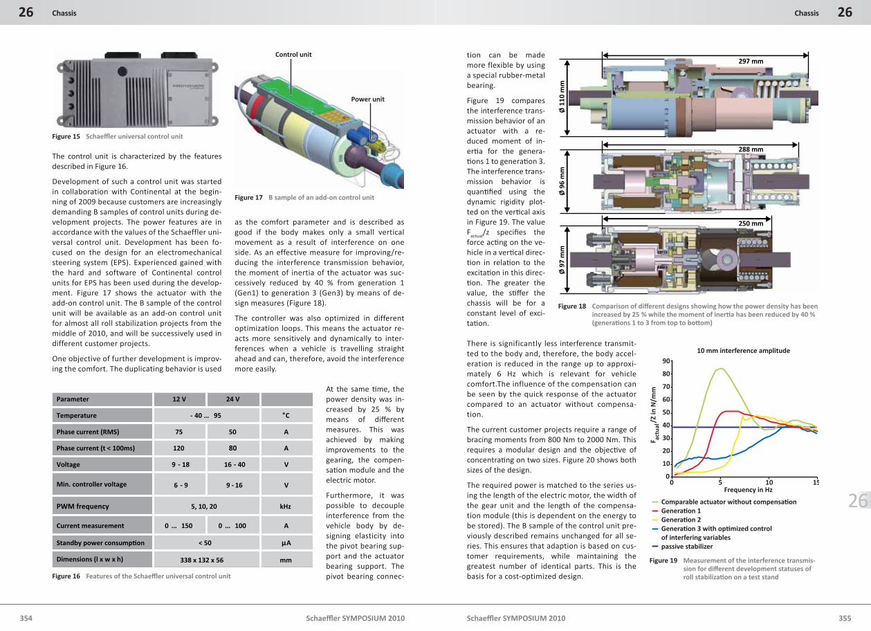
The control unit is characterized by the features described in Figure 16.
Development of such a control unit was started in collaboration with Continental at the begin-ning of 2009 because customers are increasingly demanding B samples of control units during de-velopment projects. The power features are in accordance with the values of the Schaeffler uni-versal control unit. Development has been fo-cused on the design for an electromechanical steering system (EPS). Experienced gained with the hard and software of Continental control units for EPS has been used during the develop-ment. Figure 17 shows the actuator with the add-on control unit. The B sample of the control unit will be available as an add-on control unit for almost all roll stabilization projects from the middle of 2010, and will be successively used in different customer projects.
One objective of further development is improv-ing the comfort. The duplicating behavior is used
as the comfort parameter and is described as good if the body makes only a small vertical movement as a result of interference on one side. As an effective measure for improving/re-ducing the interference transmission behavior, the moment of inertia of the actuator was suc-cessively reduced by 40 % from generation 1 (Gen1) to generation 3 (Gen3) by means of de-sign measures (Figure 18).
The controller was also optimized in different optimization loops. This means the actuator re-acts more sensitively and dynamically to inter-ferences when a vehicle is travelling straight ahead and can, therefore, avoid the interference more easily.
At the same ti me, the power density was in-creased by 25 % by means of diff erent measures. This was achieved by making improvements to the gearing, the compen-sati on module and the electric motor.
Furthermore, it was possible to decouple interference from the vehicle body by de-signing elasticity into the pivot bearing sup-port and the actuator bearing support. The pivot bearing connec-
tion can be made more flexible by using a special rubber-metal bearing.
Figure 19 compares the interference trans-mission behavior of an actuator with a re-duced moment of in-erti a for the genera-ti ons 1 to generati on 3. The interference trans-mission behavior is quanti fi ed using the dynamic rigidity plot-ted on the verti cal axis in Figure 19. The value F
actual/z specifi es the force acti ng on the ve-hicle in a verti cal direc-ti on in relati on to the excitati on in this direc-ti on. The greater the value, the sti ff er the chassis will be for a constant level of exci-tati on.
There is significantly less interference transmit-ted to the body and, therefore, the body accel-eration is reduced in the range up to approxi-mately 6 Hz which is relevant for vehicle comfort.The influence of the compensation can be seen by the quick response of the actuator compared to an actuator without compensa-tion.
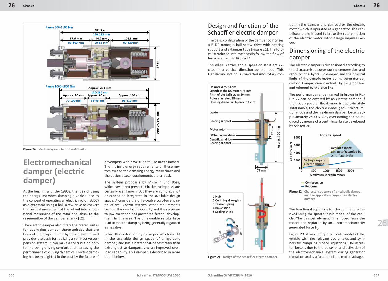
The current customer projects require a range of bracing moments from 800 Nm to 2000 Nm. This requires a modular design and the objecti ve of concentrati ng on two sizes. Figure 20 shows both sizes of the design.
The required power is matched to the series us-ing the length of the electric motor, the width of the gear unit and the length of the compensa-tion module (this is dependent on the energy to be stored). The B sample of the control unit pre-viously described remains unchanged for all se-ries. This ensures that adaption is based on cus-tomer requirements, while maintaining the greatest number of identical parts. This is the basis for a cost-optimized design.
Figure 15 Schaeffl er universal control unit
mm338 x 132 x 56Dimensions (l x w x h)
μA< 50Standby power consump�on
A0 … 1000 … 150Current measurement
kHz5, 10, 20PWM frequency
V9 - 166 - 9Min. controller voltage
V16 - 409 - 18Voltage
A80120Phase current (t < 100ms)
A5075Phase current (RMS)
°C- 40 … 95Temperature
24 V12 VParameter
Figure 16 Features of the Schaeffl er universal control unit
Control unit
Power unit
Figure 17 B sample of an add-on control unit
Ø 9
7 m
mØ
96
mm
297 mm
288 mm
250 mm
Ø 1
10 m
m
Figure 18 Comparison of diff erent designs showing how the power density has been increased by 25 % while the moment of inerti a has been reduced by 40 % (generati ons 1 to 3 from top to bott om)
Comparable actuator without compensa�onGenera�on 1Genera�on 2Genera�on 3 with op�mized control of interfering variablespassive stabilizer
Frequency in Hz
F
/Z in
N/m
m
0 5 10 15
90
80
70
60
50
40
30
20
10
0
10 mm interference amplitude
actu
al
Figure 19 Measurement of the interference transmis-sion for diff erent development statuses of roll stabilizati on on a test stand
Schaeffl er SYMPOSIUM 2010
26 Chassis
356 Schaeffl er SYMPOSIUM 2010 357
26Chassis
26
Electromechanical damper (electric damper)At the beginning of the 1990s, the idea of using the energy lost when damping a vehicle lead to the concept of operati ng an electric motor (BLDC) as a generator using a ball screw drive to convert the verti cal movement of the wheel into a rota-ti onal movement of the rotor and, thus, to the regenerati on of the damper energy [12].
The electric damper also offers the prerequisites for optimizing damper characteristics that are beyond the scope of the hydraulic system and provides the basis for realizing a semi-active sus-pension system. It can make a contribution both to improving driving comfort and increasing the performance of driving dynamics. Electric damp-ing has been blighted in the past by the failure of
developers who have tried to use linear motors. The intrinsic energy requirements of these mo-tors exceed the damping energy many times and the design space requirements are critical.
The system proposals by Michelin und Bose, which have been presented in the trade press, are certainly well known. But they are complex and/or cannot be integrated in the available design space. Alongside the unfavorable cost-benefi t ra-ti o of well-known systems, other requirements such as the overload capability and the response to low excitati on has prevented further develop-ment in this area. The unfavorable results have lead to electric damping being generally regarded as negati ve.
Schaeffler is developing a damper which will fit in the available design space of a hydraulic damper, and has a better cost-benefit ratio than existing active dampers, and an improved over-load capability. This damper is described in more detail below.
Design and functi on of the Schaeffl er electric damperThe basic configuration of the damper comprises a BLDC motor, a ball screw drive with bearing support and a damper tube (Figure 21). The forc-es introduced into the chassis follow the flow of force as shown in Figure 21.
The wheel carrier and suspension strut are ex-cited in a vertical direction by the road. This translatory motion is converted into rotary mo-
tion in the damper and damped by the electric motor which is operated as a generator. The cen-trifugal brake is used to brake the rotary motion of the electric motor rotor if large impulses oc-cur.
Dimensioning of the electric damperThe electric damper is dimensioned according to the characteristi c curve during compression and rebound of a hydraulic damper and the physical limits of the electric motor during generator op-erati on. Compression is indicate by the green line and rebound by the blue line.
The performance range marked in brown in Fig-ure 22 can be covered by an electric damper. If the travel speed of the damper is approximately 1000 mm/s, the electric motor goes into satura-tion mode and the maximum damper force is ap-proximately 2500 N. Any overloading can be re-duced by means of a centrifugal brake developed by Schaeffler.
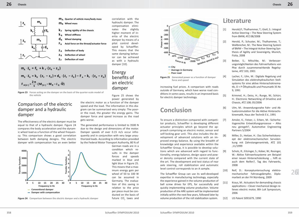
The functional equations for the damper are de-rived using the quarter-scale model of the vehi-cle. The damper element is removed from the model and replaced by an electromechanically generated force FA.
Figure 23 shows the quarter-scale model of the vehicle with the relevant coordinates and sym-bols for compiling moti on equati ons. The actua-tor force is due to the behavior and acti vati on of the electromechanical system during generator operati on and is a functi on of the motor voltage.
Approx. 250 mm220-285 mm
Approx. 80 mm
70-100 mm
Approx. 60 mm
55-65 mm
Approx. 110 mm
95-120 mm
App
rox.
107
mm
Range 1000-1800 Nm
251.3 mm
97 m
m
108.5 mm54.9 mm87.9 mm80-100 mm 50-62 mm 90-120 mm
220-282 mm
Range 500-1100 Nm
Figure 20 Modular system for roll stabilizati on
Guide
DC ball screw drive
Motor rotor
Bearing support
Bearing support
75 m
m
App
rox.
300
mm
Centrifugal drive
Damper dimensionsLength of the DC motor: 75 mmPitch of the ball screw: 10 mmRotor diameter: 28 mmHousing diameter: Approx. 73 mm
73 mm
4
4
5
33
2
2
1
4
4
5
33
2
2
1
1 Hub2 Centrifugal weights3 Tension spring4 Brake strap5 Sealing shield
Figure 21 Design of the Schaeffl er electric damper
Peak
forc
e in
N
0 500 1000 1500 2000
8000
6000
4000
2000
0
Maximum speed in mm/s
CompressionRebound
Se�ng range ofelectric damper
- Overload range- can be safeguarded by centrifugal brake
Force vs. speed
Figure 22 Characteristi c curve of a hydraulic damper and the applicati on range of an electric damper
Schaeffl er SYMPOSIUM 2010
26 Chassis
358 Schaeffl er SYMPOSIUM 2010 359
26Chassis
26
Comparison of the electric damper and a hydraulic damperThe effectiveness of the electric damper must be equal to that of a hydraulic damper. Figure 24 compares the body acceleration and the dynam-ic wheel load as a function of the wheel frequen-cy. This comparison shows a good correlation between both damping designs. The electric damper with compensation has an even better
correlation with the hydraulic damper. The compensation elimi-nates the slightly higher moment of in-ertia of the electric damper by means of a pilot control devel-oped by Schaeffler. This means that the same damping behav-ior can be achieved as with a hydraulic damper [10].
Energy benefi ts of an electric damperFigure 25 shows the power generated by
the electric motor as a function of the damper speed and the load. The information in this dia-gram can be summarized very simply: The poor-er the road, the greater the energy gains. The damper force and speed increase as the road gets worse.
The generated performance is limited to 3500 N due to the design and dimensions of the motor. Damper speeds of over 0.15 m/s occur infre-quently and in conjuncti on with very large unau-thorized loads. According to informati on provided by the Federal Motor Transport Authority, 80 % of
German roads are in a conditi on which re-sults in the damper forces and speeds marked in blue and light blue in Figure 25. This means that a max-imum energy gain per wheel of 50 to 100 W can be assumed in Germany. The evalua-ti on of this saving in relati on to the price per piece must be con-ducted on the basis of future CO2 taxes and
increasing fuel prices. A comparison with roads outside of Germany, which have worse road con-diti ons in some cases, results in an improved basis for electric damper technology.
ConclusionTo ensure a distinction compared with competi-tor products, Schaeffler is developing different actuator principles which go beyond the ap-proach comprising an electric motor, sensor and self-locking gear unit. This also includes the de-velopment of advanced solutions with an im-proved energy balance. By using the breadth of knowledge and experience available within the Schaeffler Group, it is possible to develop solu-tions which are advanced with regard to func-tionality, energy balance, design space and pow-er density compared with the current state of the art. The development and test status of rear axle steering, roll stabilization and automatic level control corresponds to an A sample.
The Schaeffl er Group can use its well-developed experti se in manufacturing technology, especially the experience gained in the volume producti on of ball screw drives for EPS, for successfully and quickly implementi ng volume producti on. Volume producti on of the ARK system will be implemented initi ally within the next few years, followed later by volume producti on of the roll stabilizati on system.
Literature[1] Herold,P.; Thalhammer, T.; Gietl, S.: Integral
Acti ve Steering – The New Steering System from BMW, ATZ 08/2008
[2] Herold, P.; Schuster, M.; Thalhammer, T.; Wallbrecher, M.: The New Steering System of BMW – The Integral-Acti ve-Steering Syn-thesis of Agility and Sovereignty, Munich, Fisita, 2008
[3] Beiker, S.; Mitschke, M.: Verbesser-ungsmöglichkeiten des Fahrverhaltens von Pkw durch zusammenwirkende Regelsy-teme, ATZ 103, 2001
[4] Lacher, F.; Ulm, M.: Digitale Regelung und Simulati on des elektrohydraulischen Stell-systems für eine akti ve Hinterachskinema-ti k, O + P Ölhydraulik und Pneumati k 35 Nr. 9, 1991
[5] Krimmel, H.; Deiss, H.; Runge, W.; Schürr, H.: Electronic Networking of Driveline and Chassis, ATZ 108; 05/2006
[6] Ulm, M.: Anwendungsnahe Fahr- und Ak-tuatorsimulati on für die Akti ve Hinterachs-kinemati k, Haus der Technik E.V., 1991
[7] Amsler, K.; Fetzer, J.; Erben, M.: Sicherhe-itsgerechte Entwicklungsprozesse – Alles neu geregelt?, Automoti ve Engineering Partners 5/2004
[8] Miller, D.; Heitzer, H.: Das Sicherheitskonz-ept der elektromechanischen Servolen-kung mit Zahnstangenantrieb, ATZ 101 ,11/1999
[9] Scholz, R.; Eitzinger, S.; Kober, W.; Rosinger, W.: Akti ve Fahrwerkssysteme am Beispiel einer neuen Hinterachslenkung … hilft es auch dem Reifen?, Tag des Fahrwerks, 2008
[10] Reif, D.: Konzeptuntersuchung elektro-mechanischer Fahrzeugdämpfer, Diplo-marbeit an der FH Nürnberg, 2009
[11] Kraus, M.: Actuators for demanding chassis applicati ons – Clever mechanical design re-lieves electric motor, 8th LuK Symposium, 2006
[12] US Patent 5091679, 1990
Az
Rz
Fk AF
Am
Rd
Fz
Rk
Rm
)( ARFAAA zzkFzm −⋅+=⋅ &&
)()()( ARFARFRRFRRR zzkFzzdzzkzm −⋅−−−⋅+−⋅=⋅ &&&&
)(2
)()(π
⋅−−⋅⋅
= GRUUA JMMsF
mA Quarter of vehicle mass/body mass mR Wheel mass k F Spring rigidity of the chassis
k R Wheel s�ffness
dR Wheel damping
FA Axial force on the thread/actuator force z A Deflec�on of body
z R Deflec�on of wheel
z F Deflec�on of road
��
Figure 23 Forces acti ng on the damper on the basis of the quarter-scale model of the vehicle
Pow
er in
W
Force in NRela�ve speed in m/s
0
-100
-200
-300
-400
-500
-600
CityAverage in GermanyPoor road
0-1750 -2625
-875
-35000,3
0,40,2
0,10
Figure 25 Generated power as a functi on of damper force and speed
Frequency in Hz
Tran
sfer
func
�on
Tran
sfer
func
�on
0 5 10 15 20 25 30
4000
3000
2000
1000
0
Conven�onal damperDamper with compensa�on
Frequency in Hz0 5 10 15 20 25 30
7
6
5
4
3
2
1
0
Figure 24 Comparison between the electric damper and a hydraulic damper