Embed Size (px)
Citation preview
© 2018 Kolpin Outdoors Inc. REV 03
2500 lb / 3500 lb / 4500 lb
ATV / UTV WINCH KIT
P/Ns: 25-9250, 25-9255, 25-9350, 25-9355, 25-9450, 25-9455
OWNER’S / OPERATING INSTRUCTIONS / SPARE PARTS
Application
WINCH MOUNT NO. 25-XXXX, OEM VEHICLE WINCH MOUNTS
Before you begin, please read these instructions and check to be sure all parts and tools are
accounted for. The following instructions contain details required to operate, install and service the
contents of this kit. Save these instructions. Important safety instructions are included in this manual.
2
© 2018 Kolpin Outdoors Inc. REV 03
TABLE OF CONTENTS
Introduction
Introduction ���������������...���...���������������..�. 3
Guidebook Conventions �����..������..�...��������������..��.. 3
Controls and Features ������������������������������..��.�.. 4
Winch ��������������������..�������������..�.���.. 4
Assembly �����������������������������������...��.��. 5
Mounting ���������������...���������������������... 5
Mounting the winch ���������������������������..��. 5
Mounting the handlebar switch ���������..�������������.�... 6
Mounting the contactor/solenoid ������.���������������.�.�. 6
Mounting the remote switch (optional) �������...�������������... 7
Wiring the winch �����������������������������...���..� 7
Winch Wiring diagram ��������������...��������������..��.. 8
Corded Remote and Rocker Switch Wiring Diagram ………………………………………………… 9
ATV/UTV Winch User Guide ����������������������������..�.�� 10
Winch Safety Precautions �������������������������....... 10-11
Winch Operation ����������������...�������������... 12-14
Wire Cable Care ����������.������������������....�.. 14
Shock loading ���������������...���������������.� 15
Winch Maintenance and Service Safety ����������������������...��.�. 16
Lubrication ����������������������������������.��.. 16
Cable Assembly Replacement ��������������������...������..... 16
Specifications ��������������������������...�����������. 17
Performance Specifications ���������������������...�������.. 17
Parts Kit Diagrams and replacement part numbers �������������������. 18-23
Troubleshooting ������������������.���.�������������.�.� 24
Warranty ����������������������.�������������...����.. 25
3
© 2018 Kolpin Outdoors Inc. REV 03
INTRODUCTION
Congratulations on your purchase of a Kolpin winch! The Kolpin winch works great for vehicle recovery and plow lift applications. With
proper use and maintenance, this winch will bring many years of satisfying service.
Every effort has been made to ensure the accuracy and completeness of the information in this manual. We reserve te right to change,
alter and/or improve the product and this document at any time without prior notice.
Record the part numbers, date of purchase and place of purchase for future reference. Please have this information available when
ordering parts and when making technical or warranty inquiries.
Kolpin Outdoors Support
1-877-956-5746
Part Number
Date of Purchase
Purchase Location
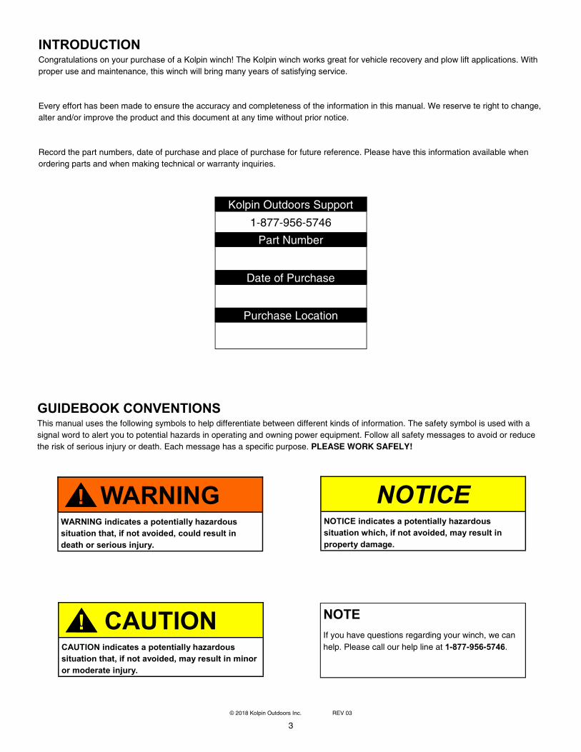
GUIDEBOOK CONVENTIONS
This manual uses the following symbols to help differentiate between different kinds of information. The safety symbol is used with a
signal word to alert you to potential hazards in operating and owning power equipment. Follow all safety messages to avoid or reduce
the risk of serious injury or death. Each message has a specific purpose. PLEASE WORK SAFELY!
WARNING
! WARNING indicates a potentially hazardous
situation that, if not avoided, could result in
death or serious injury.
CAUTION
! CAUTION indicates a potentially hazardous
situation that, if not avoided, may result in minor
or moderate injury.
NOTICE NOTICE indicates a potentially hazardous
situation which, if not avoided, may result in
property damage.
NOTE
If you have questions regarding your winch, we can
help. Please call our help line at 1-877-956-5746.
4
© 2018 Kolpin Outdoors Inc. REV 03
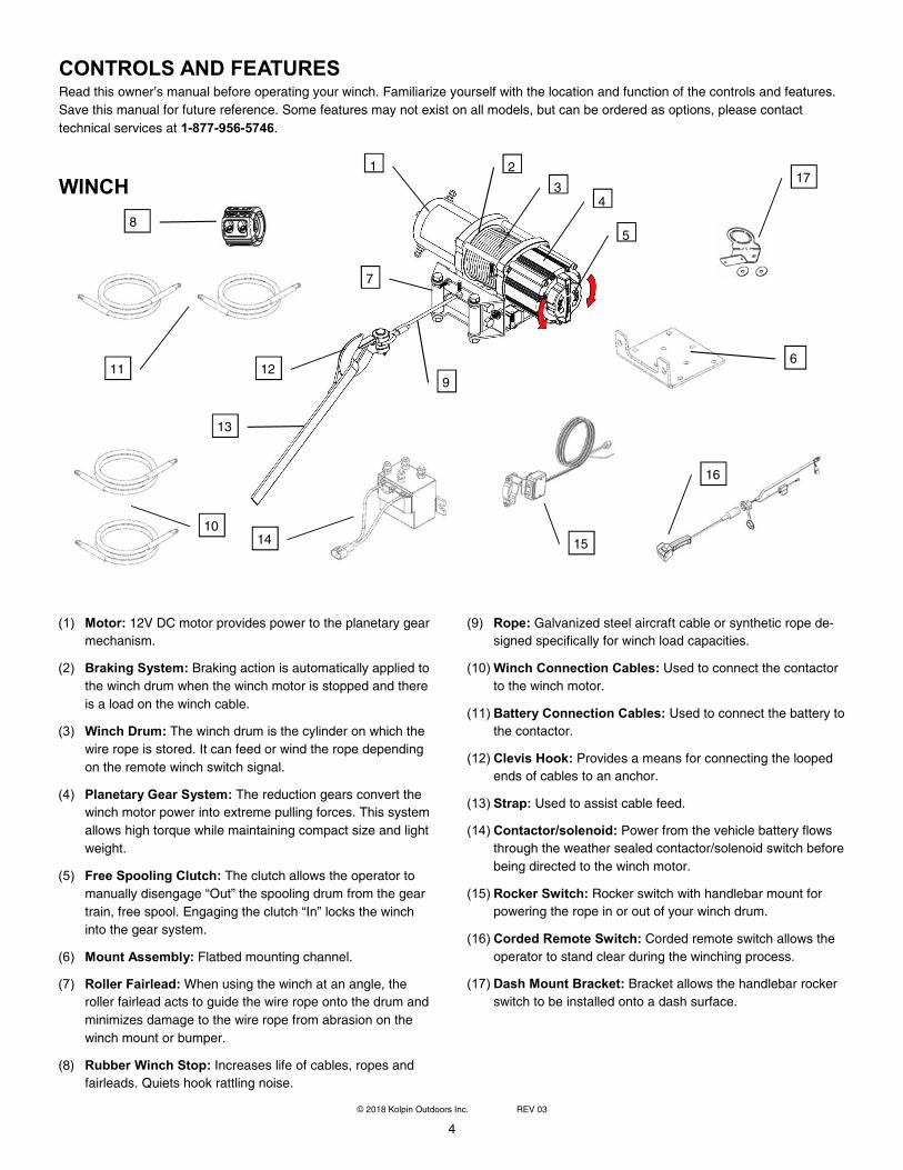
CONTROLS AND FEATURES
Read this owner’s manual before operating your winch. Familiarize yourself with the location and function of the controls and features.
Save this manual for future reference. Some features may not exist on all models, but can be ordered as options, please contact
technical services at 1-877-956-5746.
WINCH
(1) Motor: 12V DC motor provides power to the planetary gear
mechanism.
(2) Braking System: Braking action is automatically applied to
the winch drum when the winch motor is stopped and there
is a load on the winch cable.
(3) Winch Drum: The winch drum is the cylinder on which the
wire rope is stored. It can feed or wind the rope depending
on the remote winch switch signal.
(4) Planetary Gear System: The reduction gears convert the
winch motor power into extreme pulling forces. This system
allows high torque while maintaining compact size and light
weight.
(5) Free Spooling Clutch: The clutch allows the operator to
manually disengage “Out” the spooling drum from the gear
train, free spool. Engaging the clutch “In” locks the winch
into the gear system.
(6) Mount Assembly: Flatbed mounting channel.
(7) Roller Fairlead: When using the winch at an angle, the
roller fairlead acts to guide the wire rope onto the drum and
minimizes damage to the wire rope from abrasion on the
winch mount or bumper.
(8) Rubber Winch Stop: Increases life of cables, ropes and
fairleads. Quiets hook rattling noise.
(9) Rope: Galvanized steel aircraft cable or synthetic rope de-
signed specifically for winch load capacities.
(10) Winch Connection Cables: Used to connect the contactor
to the winch motor.
(11) Battery Connection Cables: Used to connect the battery to
the contactor.
(12) Clevis Hook: Provides a means for connecting the looped
ends of cables to an anchor.
(13) Strap: Used to assist cable feed.
(14) Contactor/solenoid: Power from the vehicle battery flows
through the weather sealed contactor/solenoid switch before
being directed to the winch motor.
(15) Rocker Switch: Rocker switch with handlebar mount for
powering the rope in or out of your winch drum.
(16) Corded Remote Switch: Corded remote switch allows the
operator to stand clear during the winching process.
(17) Dash Mount Bracket: Bracket allows the handlebar rocker
switch to be installed onto a dash surface.
1 2
3
4
5
7
9
10
11 12
13
14 15
6
16
8
17
5
© 2018 Kolpin Outdoors Inc. REV 03
ASSEMBLY
The winch kit comes mostly assembled from the factory. Some pre-assembly of the kit is required for installation into vehicles.
BEFORE YOU BEGIN:
• Your Kolpin accessory is designed for a universe fit for most vehicles.
• Please read and understand all instructions.
• Verify all parts and tools are accounted for.
• To ensure a satisfactory installation, follow all steps cor-rectly and in the sequence described.
• To facilitate installation, make sure that your vehicle is clean and free of debris.
• All directions referring to right and left are when the rider is sitting on the machine.
TOOLS REQUIRED:
• Basic metric wrench set
• Basic metric socket set
• Pliers
• Philips screwdriver
Rotate to
lock or un-
lock spool
Mount
plate
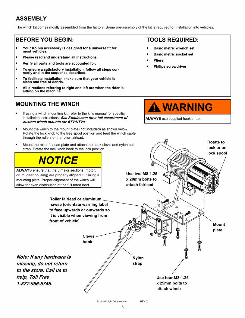
MOUNTING THE WINCH
• If using a winch mounting kit, refer to the kit’s manual for specific
installation instructions. See Kolpin.com for a full assortment of custom winch mounts for ATV/UTVs.
• Mount the winch to the mount plate (not included) as shown below. Rotate the lock knob to the free spool position and feed the winch cable through the rollers of the roller fairlead.
• Mount the roller fairlead plate and attach the hook clevis and nylon pull strap. Rotate the lock knob back to the lock position.
Use four M8-1.25
x 25mm bolts to
attach winch
Nylon
strap
Clevis
hook
Roller fairlead or aluminum
hawse (orientate warning label
to face upwards or outwards so
it is visible when viewing from
front of vehicle)
Use two M8-1.25
x 20mm bolts to
attach fairlead
NOTICE
ALWAYS ensure that the 3 major sections (motor,
drum, gear housing) are properly aligned if utilizing a
mounting plate. Proper alignment of the winch will
allow for even distribution of the full rated load.
WARNING
! ALWAYS use supplied hook strap.
Note: If any hardware is
missing, do not return
to the store. Call us to
help, Toll Free
1-877-956-5746.
6
© 2018 Kolpin Outdoors Inc. REV 03
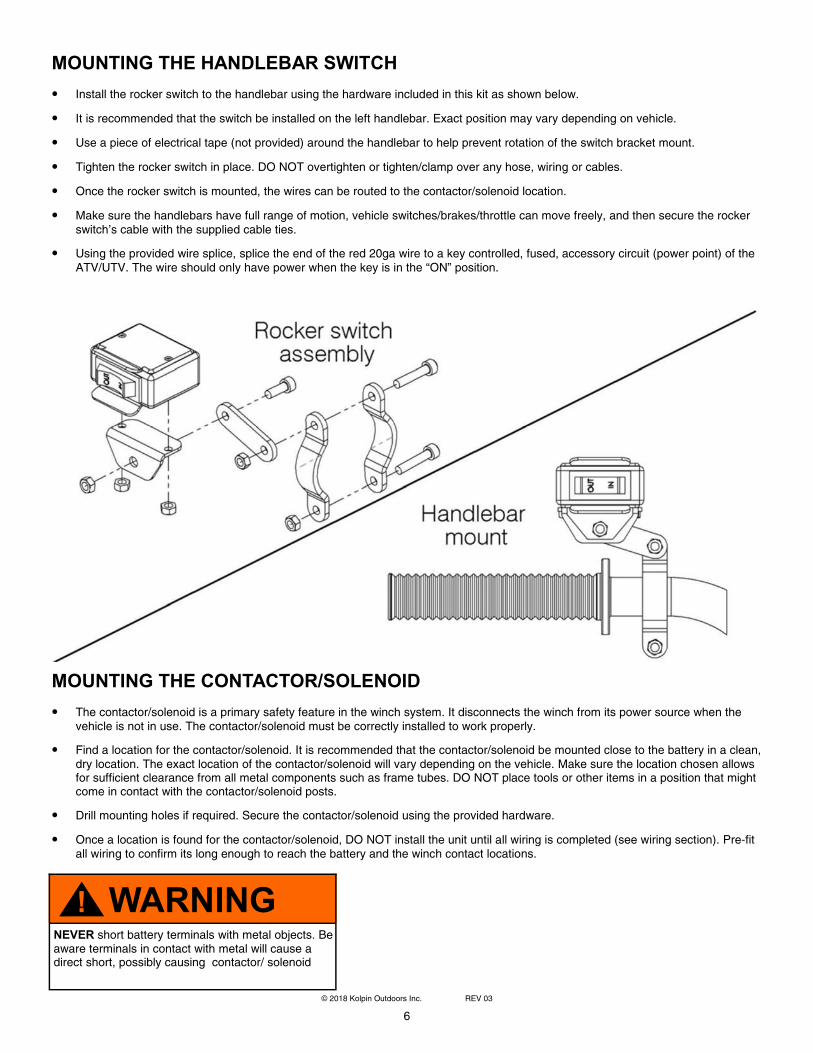
MOUNTING THE HANDLEBAR SWITCH
• Install the rocker switch to the handlebar using the hardware included in this kit as shown below.
• It is recommended that the switch be installed on the left handlebar. Exact position may vary depending on vehicle.
• Use a piece of electrical tape (not provided) around the handlebar to help prevent rotation of the switch bracket mount.
• Tighten the rocker switch in place. DO NOT overtighten or tighten/clamp over any hose, wiring or cables.
• Once the rocker switch is mounted, the wires can be routed to the contactor/solenoid location.
• Make sure the handlebars have full range of motion, vehicle switches/brakes/throttle can move freely, and then secure the rocker switch’s cable with the supplied cable ties.
• Using the provided wire splice, splice the end of the red 20ga wire to a key controlled, fused, accessory circuit (power point) of the ATV/UTV. The wire should only have power when the key is in the “ON” position.
MOUNTING THE CONTACTOR/SOLENOID
• The contactor/solenoid is a primary safety feature in the winch system. It disconnects the winch from its power source when the vehicle is not in use. The contactor/solenoid must be correctly installed to work properly.
• Find a location for the contactor/solenoid. It is recommended that the contactor/solenoid be mounted close to the battery in a clean, dry location. The exact location of the contactor/solenoid will vary depending on the vehicle. Make sure the location chosen allows for sufficient clearance from all metal components such as frame tubes. DO NOT place tools or other items in a position that might come in contact with the contactor/solenoid posts.
• Drill mounting holes if required. Secure the contactor/solenoid using the provided hardware.
• Once a location is found for the contactor/solenoid, DO NOT install the unit until all wiring is completed (see wiring section). Pre-fit all wiring to confirm its long enough to reach the battery and the winch contact locations.
WARNING
! NEVER short battery terminals with metal objects. Be aware terminals in contact with metal will cause a direct short, possibly causing contactor/ solenoid
7
© 2018 Kolpin Outdoors Inc. REV 03
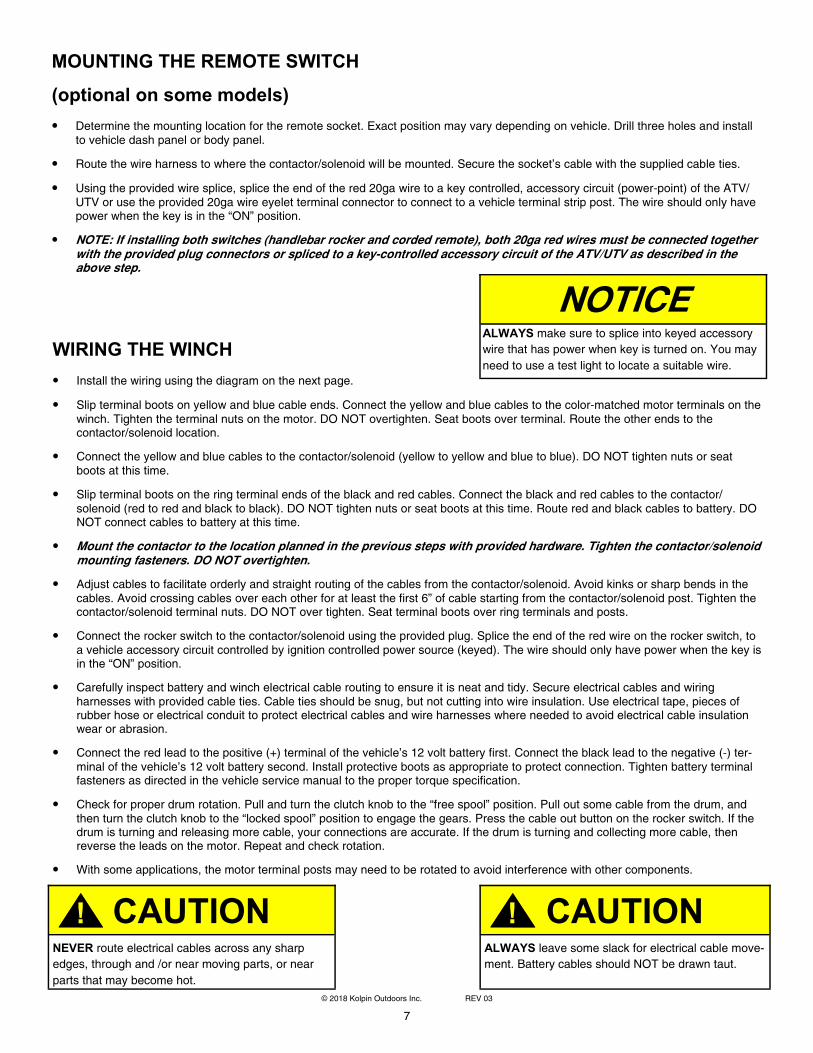
MOUNTING THE REMOTE SWITCH
(optional on some models)
• Determine the mounting location for the remote socket. Exact position may vary depending on vehicle. Drill three holes and install to vehicle dash panel or body panel.
• Route the wire harness to where the contactor/solenoid will be mounted. Secure the socket’s cable with the supplied cable ties.
• Using the provided wire splice, splice the end of the red 20ga wire to a key controlled, accessory circuit (power-point) of the ATV/UTV or use the provided 20ga wire eyelet terminal connector to connect to a vehicle terminal strip post. The wire should only have power when the key is in the “ON” position.
• NOTE: If installing both switches (handlebar rocker and corded remote), both 20ga red wires must be connected together with the provided plug connectors or spliced to a key-controlled accessory circuit of the ATV/UTV as described in the above step.
WIRING THE WINCH
• Install the wiring using the diagram on the next page.
• Slip terminal boots on yellow and blue cable ends. Connect the yellow and blue cables to the color-matched motor terminals on the winch. Tighten the terminal nuts on the motor. DO NOT overtighten. Seat boots over terminal. Route the other ends to the contactor/solenoid location.
• Connect the yellow and blue cables to the contactor/solenoid (yellow to yellow and blue to blue). DO NOT tighten nuts or seat boots at this time.
• Slip terminal boots on the ring terminal ends of the black and red cables. Connect the black and red cables to the contactor/solenoid (red to red and black to black). DO NOT tighten nuts or seat boots at this time. Route red and black cables to battery. DO NOT connect cables to battery at this time.
• Mount the contactor to the location planned in the previous steps with provided hardware. Tighten the contactor/solenoid mounting fasteners. DO NOT overtighten.
• Adjust cables to facilitate orderly and straight routing of the cables from the contactor/solenoid. Avoid kinks or sharp bends in the cables. Avoid crossing cables over each other for at least the first 6” of cable starting from the contactor/solenoid post. Tighten the contactor/solenoid terminal nuts. DO NOT over tighten. Seat terminal boots over ring terminals and posts.
• Connect the rocker switch to the contactor/solenoid using the provided plug. Splice the end of the red wire on the rocker switch, to a vehicle accessory circuit controlled by ignition controlled power source (keyed). The wire should only have power when the key is in the “ON” position.
• Carefully inspect battery and winch electrical cable routing to ensure it is neat and tidy. Secure electrical cables and wiring harnesses with provided cable ties. Cable ties should be snug, but not cutting into wire insulation. Use electrical tape, pieces of rubber hose or electrical conduit to protect electrical cables and wire harnesses where needed to avoid electrical cable insulation wear or abrasion.
• Connect the red lead to the positive (+) terminal of the vehicle’s 12 volt battery first. Connect the black lead to the negative (-) ter-minal of the vehicle’s 12 volt battery second. Install protective boots as appropriate to protect connection. Tighten battery terminal fasteners as directed in the vehicle service manual to the proper torque specification.
• Check for proper drum rotation. Pull and turn the clutch knob to the “free spool” position. Pull out some cable from the drum, and then turn the clutch knob to the “locked spool” position to engage the gears. Press the cable out button on the rocker switch. If the drum is turning and releasing more cable, your connections are accurate. If the drum is turning and collecting more cable, then reverse the leads on the motor. Repeat and check rotation.
• With some applications, the motor terminal posts may need to be rotated to avoid interference with other components.
CAUTION
! NEVER route electrical cables across any sharp
edges, through and /or near moving parts, or near
parts that may become hot.
CAUTION
! ALWAYS leave some slack for electrical cable move-
ment. Battery cables should NOT be drawn taut.
NOTICE
ALWAYS make sure to splice into keyed accessory
wire that has power when key is turned on. You may
need to use a test light to locate a suitable wire.
8
© 2018 Kolpin Outdoors Inc. REV 03
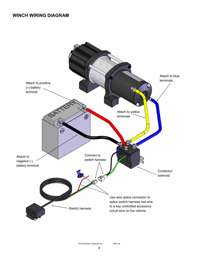
WINCH WIRING DIAGRAM
Attach to blue
terminals
Attach to yellow
terminals
Contactor/
solenoid
Attach to positive
(+) battery
terminal
Attach to
negative (-)
battery terminal
Switch harness
Use wire splice connector to
splice switch harness red wire
to a key controlled accessory
circuit wire on the vehicle
Connect to
switch harness
9
© 2018 Kolpin Outdoors Inc. REV 03
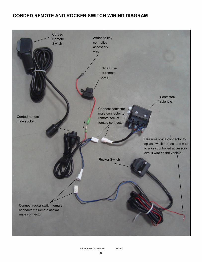
CORDED REMOTE AND ROCKER SWITCH WIRING DIAGRAM
Attach to key
controlled
accessory
wire
Contactor/
solenoid
Corded
Remote
Switch
Corded remote
male socket
Rocker Switch
Use wire splice connector to
splice switch harness red wire
to a key controlled accessory
circuit wire on the vehicle
Connect contactor
male connector to
remote socket
female connector
Connect rocker switch female
connector to remote socket
male connector
Inline Fuse
for remote
power
10
© 2018 Kolpin Outdoors Inc. REV 03
ATV/UTV WINCH USER GUIDE
Before you begin using your winch, read and understand the guide. Please retain this guide for future reference.
These safety warnings and instructions apply if you choose to add an accessory winch to your vehicle.
Your winch may have a cable made of either wire rope or specially designed synthetic rope. The term “winch cable” will be used for
either unless noted otherwise.
WINCH SAFETY PRECAUTIONS
1. Read all sections of this manual.
2. Never use alcohol or drugs before or while operating the winch.
3. Never allow children under 16 years of age to operate the winch.
4. Always wear eye protection and heavy gloves when operating the winch.
5. Always keep body, hair, clothing and jewelry clear of the winch cable, fairlead and hook when operating winch.
6. Never attempt to “jerk” a load attached to the winch with a moving vehicle. See the Shock Loading section on page 15.
7. Always keep the area around the vehicle, winch, winch cable and load clear of people (especially children) and distractions while
operating the winch.
8. Always turn the vehicle ignition power OFF when it and the winch are not being used.
9. Always be sure that at least five full turns of winch cable are wrapped around the winch drum at all times. The friction provided by
this wrapped cable allows the drum to pull on the winch cable and move the load.
10. Always apply your vehicle’s park brake and/or park mechanism to hold the vehicle in place during winching. Use wheel chocks if
needed.
11. Always align the vehicle and winch with the load directly in front of the vehicle as much as possible. Avoid winching with the winch
cable at an angle to the winching vehicle’s center line whenever possible.
12. If winching at an angle is unavoidable, follow these precautions:
A. Look at the winch drum occasionally. Never let the winch cable “stack” or accumulate at one end of the winch drum. Too
much winch cable at one end of the winch drum can damage the winch and the winch cable.
B. If stacking occurs, stop winching. Follow step 15 on page 4 to feed and rewind the cable evenly before continuing the
winch operation.
13. Never winch up or down at sharp angles. This can destabilize the winching vehicle and possibly cause it to move without warning.
14. Never attempt to winch loads that weigh more than the winch’s rated capacity.
15. The winch motor may become hot during winch use. If you winch for more than 45 seconds, or if the winch stalls during operation,
stop winching and permit the winch to cool down for 10 minutes before using it again.
WARNING
! ALWAYS follow all winch instructions and warnings in this manual. Improper winch use can result in SEVERE INJURY or DEATH.
11
© 2018 Kolpin Outdoors Inc. REV 03
WINCH SAFETY PRECAUTIONS (continued)
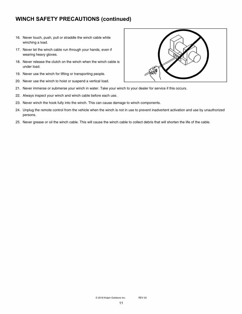
16. Never touch, push, pull or straddle the winch cable while
winching a load.
17. Never let the winch cable run through your hands, even if
wearing heavy gloves.
18. Never release the clutch on the winch when the winch cable is
under load.
19. Never use the winch for lifting or transporting people.
20. Never use the winch to hoist or suspend a vertical load.
21. Never immerse or submerse your winch in water. Take your winch to your dealer for service if this occurs.
22. Always inspect your winch and winch cable before each use.
23. Never winch the hook fully into the winch. This can cause damage to winch components.
24. Unplug the remote control from the vehicle when the winch is not in use to prevent inadvertent activation and use by unauthorized
persons.
25. Never grease or oil the winch cable. This will cause the winch cable to collect debris that will shorten the life of the cable.
12
© 2018 Kolpin Outdoors Inc. REV 03
WINCH OPERATION
Read the Winch Safety Precautions in the preceding pages before using your winch.
TIP: Consider practicing the operation and use or your winch before you actually need to use it in the field.
Each winching situation is unique:
• Take your time to think through the winching you are about to do.
• Proceed slowly and deliberately.
• Never hurry or rush during winching.
• Always pay attention to your surroundings.
• You may need to change your winching strategy if it is not working.
• Always remember that your winch is very powerful.
• There are simply some situations that you and your winch will not be able to deal with. Do not be afraid to ask others to
help when this happens.
1. Always inspect the vehicle, winch, winch cable and winch controls for any signs of damage or parts in need of repair or
replacement before each use. Pay particular attention to the first three feet (one meter) of the winch cable if the winch is
being used (or has been used) for lifting an accessory plow assembly. Promptly replace any worn or damaged cable.
2. Never operate a winch or a vehicle in need of repair or service.
3. Always apply your vehicle’s parking brake and/or park mechanism to hold the vehicle in place during winching. Use wheel chocks if
needed.
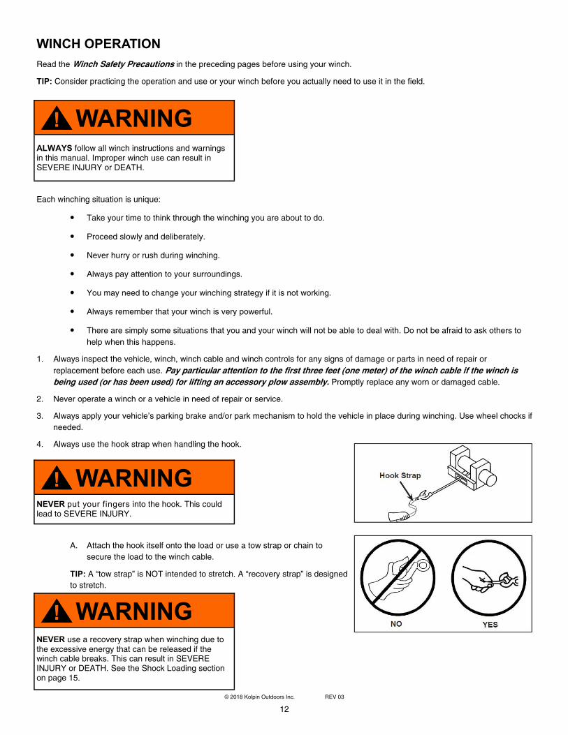
4. Always use the hook strap when handling the hook.
A. Attach the hook itself onto the load or use a tow strap or chain to
secure the load to the winch cable.
TIP: A “tow strap” is NOT intended to stretch. A “recovery strap” is designed
to stretch.
WARNING
!
ALWAYS follow all winch instructions and warnings in this manual. Improper winch use can result in SEVERE INJURY or DEATH.
WARNING
! NEVER put your fingers into the hook. This could lead to SEVERE INJURY.
WARNING
! NEVER use a recovery strap when winching due to the excessive energy that can be released if the winch cable breaks. This can result in SEVERE INJURY or DEATH. See the Shock Loading section on page 15.
13
© 2018 Kolpin Outdoors Inc. REV 03
WINCH OPERATION (continued)
B. Never hook the winch cable back onto itself. This will damage the winch cable and may result in winch cable failure.
C. If possible, keep the winch cable aligned with the center line of the
winching vehicle. This will help the spooling of the winch cable and
reduce the load on the fairlead.
D. If freeing a stuck vehicle by attaching to a tree, use an item such as a
tow strap to avoid damaging the tree during winch operation. Sharp
cables and chains can damage and even kill trees. Please remember
to Tread Lightly® (treadlightly.org).
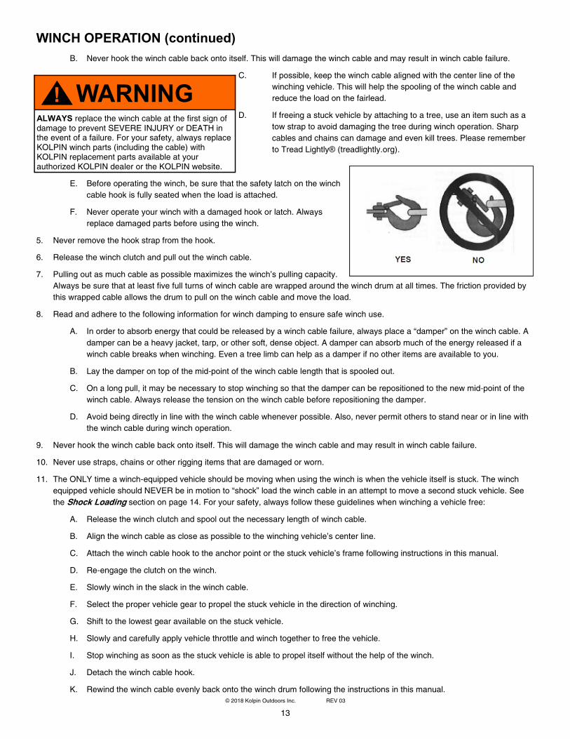
E. Before operating the winch, be sure that the safety latch on the winch
cable hook is fully seated when the load is attached.
F. Never operate your winch with a damaged hook or latch. Always
replace damaged parts before using the winch.
5. Never remove the hook strap from the hook.
6. Release the winch clutch and pull out the winch cable.
7. Pulling out as much cable as possible maximizes the winch’s pulling capacity.
Always be sure that at least five full turns of winch cable are wrapped around the winch drum at all times. The friction provided by
this wrapped cable allows the drum to pull on the winch cable and move the load.
8. Read and adhere to the following information for winch damping to ensure safe winch use.
A. In order to absorb energy that could be released by a winch cable failure, always place a “damper” on the winch cable. A
damper can be a heavy jacket, tarp, or other soft, dense object. A damper can absorb much of the energy released if a
winch cable breaks when winching. Even a tree limb can help as a damper if no other items are available to you.
B. Lay the damper on top of the mid-point of the winch cable length that is spooled out.
C. On a long pull, it may be necessary to stop winching so that the damper can be repositioned to the new mid-point of the
winch cable. Always release the tension on the winch cable before repositioning the damper.
D. Avoid being directly in line with the winch cable whenever possible. Also, never permit others to stand near or in line with
the winch cable during winch operation.
9. Never hook the winch cable back onto itself. This will damage the winch cable and may result in winch cable failure.
10. Never use straps, chains or other rigging items that are damaged or worn.
11. The ONLY time a winch-equipped vehicle should be moving when using the winch is when the vehicle itself is stuck. The winch
equipped vehicle should NEVER be in motion to “shock” load the winch cable in an attempt to move a second stuck vehicle. See
the Shock Loading section on page 14. For your safety, always follow these guidelines when winching a vehicle free:
A. Release the winch clutch and spool out the necessary length of winch cable.
B. Align the winch cable as close as possible to the winching vehicle’s center line.
C. Attach the winch cable hook to the anchor point or the stuck vehicle’s frame following instructions in this manual.
D. Re-engage the clutch on the winch.
E. Slowly winch in the slack in the winch cable.
F. Select the proper vehicle gear to propel the stuck vehicle in the direction of winching.
G. Shift to the lowest gear available on the stuck vehicle.
H. Slowly and carefully apply vehicle throttle and winch together to free the vehicle.
I. Stop winching as soon as the stuck vehicle is able to propel itself without the help of the winch.
J. Detach the winch cable hook.
K. Rewind the winch cable evenly back onto the winch drum following the instructions in this manual.
WARNING
! ALWAYS replace the winch cable at the first sign of damage to prevent SEVERE INJURY or DEATH in the event of a failure. For your safety, always replace KOLPIN winch parts (including the cable) with KOLPIN replacement parts available at your authorized KOLPIN dealer or the KOLPIN website.
14
© 2018 Kolpin Outdoors Inc. REV 03
WINCH OPERATION (continued)
12. Never attempt to winch another stuck vehicle by attaching the winch cable to a suspension component, brush guard, bumper or
cargo rack. Vehicle damage may result. Instead, attach the winch to a strong portion of the vehicle frame or hitch.
13. Extensive winching will run down the battery on the winching vehicle. Let the winching vehicle’s engine run while operating the
winch to prevent the battery from running low if winching for long periods.
14. The winch motor may become hot during winch use. If you winch for more than 45 seconds, or if the winch stalls during operation,
stop winching and permit the winch to cool down for 10 minutes before using it again.
15. After winching is complete, especially if winching at an angle, it may be necessary to re-distribute the winch cable across the winch
drum. You will need an assistant to perform this task.
A. Release the clutch on the winch.
B. Feed out the winch cable that is unevenly bunched up in one area.
C. Re-engage the winch clutch.
D. Have an assistant pull the winch cable tightly with about 100 lbs. (45 kg) of tension using the hook strap.
E. Slowly winch the cable in while your assistant moves the end of the winch cable back and forth horizontally to evenly dis-
tribute the winch cable on the drum.
F. Doing this reduces the chances of the winch cable “wedging” itself between lower layers of winch cable.
WINCH CABLE CARE
For your safety, always replace KOLPIN winch parts (including the cable) with KOLPIN replacement parts available at your authorized
KOLPIN dealer or the KOLPIN website (Kolpin.com).
1. Always inspect your winch before each use. Inspect for worn or loose parts including mounting hardware. Never use the winch if
any part needs repair or replacement.
2. Always inspect your winch cable before each use. Inspect for worn or kinked winch cable.
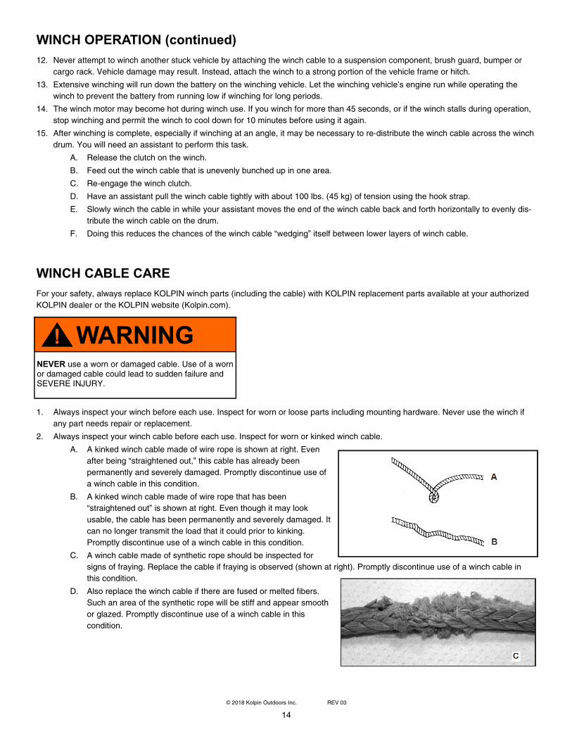
A. A kinked winch cable made of wire rope is shown at right. Even
after being “straightened out,” this cable has already been
permanently and severely damaged. Promptly discontinue use of
a winch cable in this condition.
B. A kinked winch cable made of wire rope that has been
“straightened out” is shown at right. Even though it may look
usable, the cable has been permanently and severely damaged. It
can no longer transmit the load that it could prior to kinking.
Promptly discontinue use of a winch cable in this condition.
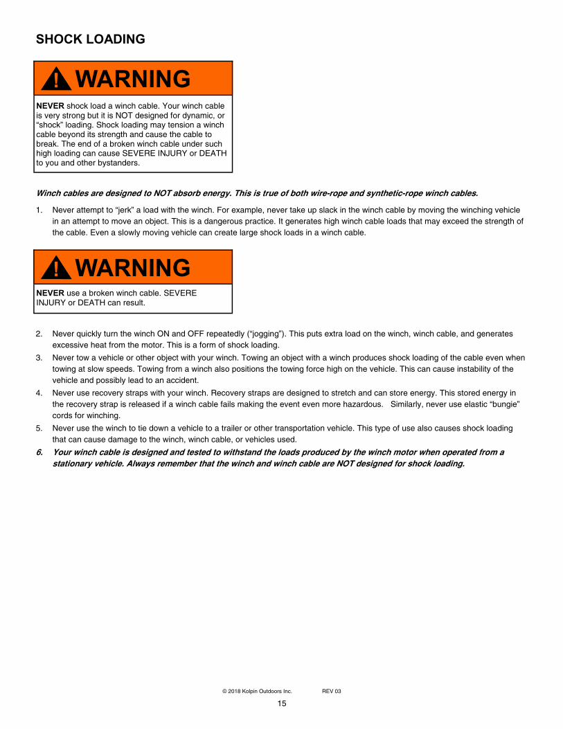
C. A winch cable made of synthetic rope should be inspected for
signs of fraying. Replace the cable if fraying is observed (shown at right). Promptly discontinue use of a winch cable in
this condition.
D. Also replace the winch cable if there are fused or melted fibers.
Such an area of the synthetic rope will be stiff and appear smooth
or glazed. Promptly discontinue use of a winch cable in this
condition.
WARNING
! NEVER use a worn or damaged cable. Use of a worn or damaged cable could lead to sudden failure and SEVERE INJURY.
15
© 2018 Kolpin Outdoors Inc. REV 03
SHOCK LOADING
Winch cables are designed to NOT absorb energy. This is true of both wire-rope and synthetic-rope winch cables.
1. Never attempt to “jerk” a load with the winch. For example, never take up slack in the winch cable by moving the winching vehicle
in an attempt to move an object. This is a dangerous practice. It generates high winch cable loads that may exceed the strength of
the cable. Even a slowly moving vehicle can create large shock loads in a winch cable.
2. Never quickly turn the winch ON and OFF repeatedly (“jogging”). This puts extra load on the winch, winch cable, and generates
excessive heat from the motor. This is a form of shock loading.
3. Never tow a vehicle or other object with your winch. Towing an object with a winch produces shock loading of the cable even when
towing at slow speeds. Towing from a winch also positions the towing force high on the vehicle. This can cause instability of the
vehicle and possibly lead to an accident.
4. Never use recovery straps with your winch. Recovery straps are designed to stretch and can store energy. This stored energy in
the recovery strap is released if a winch cable fails making the event even more hazardous. Similarly, never use elastic “bungie”
cords for winching.
5. Never use the winch to tie down a vehicle to a trailer or other transportation vehicle. This type of use also causes shock loading
that can cause damage to the winch, winch cable, or vehicles used.
6. Your winch cable is designed and tested to withstand the loads produced by the winch motor when operated from a
stationary vehicle. Always remember that the winch and winch cable are NOT designed for shock loading.
WARNING
! NEVER use a broken winch cable. SEVERE INJURY or DEATH can result.
WARNING
! NEVER shock load a winch cable. Your winch cable is very strong but it is NOT designed for dynamic, or “shock” loading. Shock loading may tension a winch cable beyond its strength and cause the cable to break. The end of a broken winch cable under such high loading can cause SEVERE INJURY or DEATH to you and other bystanders.
16
© 2018 Kolpin Outdoors Inc. REV 03
WINCH MAINTENANCE AND SERVICE SAFETY
1. Always inspect your winch before each use. Inspect for worn or kinked winch cable. Also inspect for worn or loose parts including
mounting hardware.
2. Permit your winch motor to cool down prior to servicing your winch.
3. Never work on your winch without first disconnecting the battery connections to prevent accidental activation of the winch
4. For your safety, always replace KOLPIN winch parts (including the cable) with KOLPIN replacement parts available at your
authorized KOLPIN dealer or the KOLPIN website (Kolpin.com).
5. Some winch models use wire rope as the winch cable. Other winches use a specially designed synthetic rope as the winch cable.
6. Never replace a synthetic-rope winch cable with a consumer-grade polymer rope such as can be purchased in a hardware store.
Although they may look similar, they are NOT alike. A polymer rope not designed for winch use will stretch and store excessive
energy when winching.
LUBRICATION
All moving parts within the electric winch have been lubricated using high temperature grease at the factory. No internal lubrication is
required. Never grease or oil the winch cable. This will cause the winch cable to collect debris that will shorten the life of the cable.
CABLE ASSEMBLY REPLACEMENT
It is recommended that only KOLPIN supplied parts be used.
1. Move the clutch to the “free-spool” position.
2. Extend cable assembly to its full length. Note how the existing cable is connected to the inside of the drum.
3. Remove old cable assembly and attach new one.
4. Retract cable assembly onto drum being careful not to allow kinking.
WARNING
! ALWAYS follow all winch instructions and warnings in this manual. Improper or lack of winch maintenance and service could lead to SEVERE INJURY or DEATH.
NOTE
For service or parts assistance, contact our help line
at 1-877-956-5746.
WARNING
! ALWAYS be aware that failure of a stretched rope under winching conditions will release all of the stored energy. This will increase the chances of SEVERE INJURY or DEATH.
17
© 2018 Kolpin Outdoors Inc. REV 03
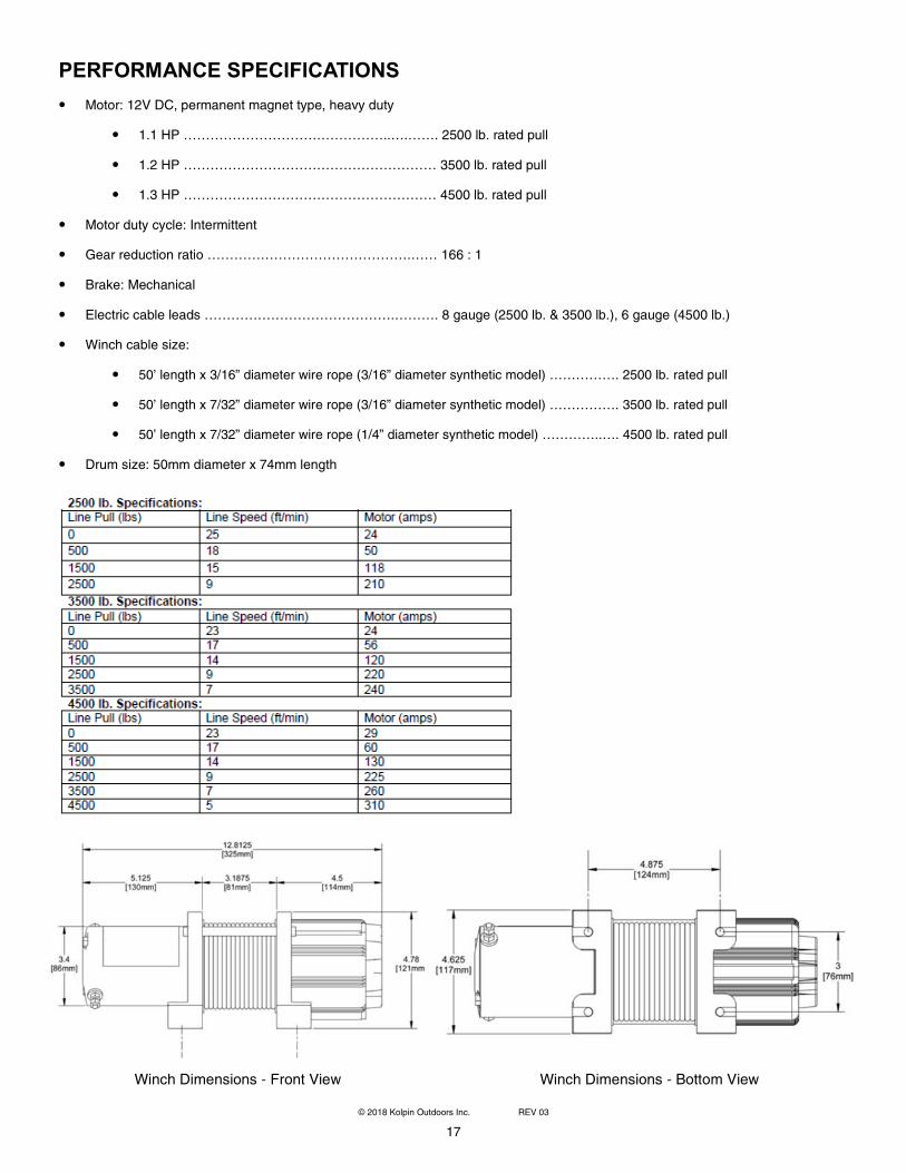
Winch Dimensions - Front View Winch Dimensions - Bottom View
PERFORMANCE SPECIFICATIONS
• Motor: 12V DC, permanent magnet type, heavy duty
• 1.1 HP ………………………………………..….……. 2500 lb. rated pull
• 1.2 HP ………………………………………………… 3500 lb. rated pull
• 1.3 HP ………………………………………………… 4500 lb. rated pull
• Motor duty cycle: Intermittent
• Gear reduction ratio ……………………………………….…… 166 : 1
• Brake: Mechanical
• Electric cable leads …………………………………….………. 8 gauge (2500 lb. & 3500 lb.), 6 gauge (4500 lb.)
• Winch cable size:
• 50’ length x 3/16” diameter wire rope (3/16” diameter synthetic model) ……………. 2500 lb. rated pull
• 50’ length x 7/32” diameter wire rope (3/16” diameter synthetic model) ……………. 3500 lb. rated pull
• 50’ length x 7/32” diameter wire rope (1/4” diameter synthetic model) …………..…. 4500 lb. rated pull
• Drum size: 50mm diameter x 74mm length
18
© 2018 Kolpin Outdoors Inc. REV 03
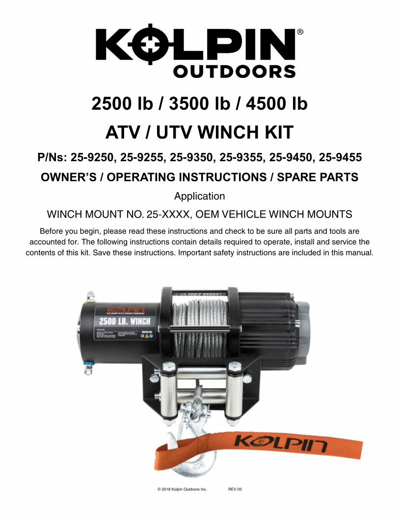
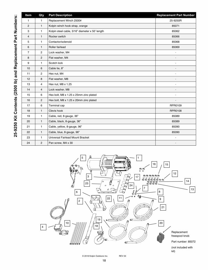
25-9250 Kit Contents (2500 lb) and Replacement Part Numbers: Item Qty Part Description Replacement Part Number
1 1 Replacement Winch 2500# 25-9250R
2 1 Kolpin winch hook strap, orange 85071
3 1 Kolpin steel cable, 3/16” diameter x 50’ length 85062
4 1 Rocker switch 85066
5 1 Contactor/solenoid 85068
6 1 Roller fairlead 85069
7 2 Lock washer, M4 -
8 2 Flat washer, M4 -
9 1 Scotch lock -
10 6 Cable tie, 8” -
11 2 Hex nut, M4 -
12 8 Flat washer, M8 -
13 4 Hex nut, M8 x 1.25 -
14 4 Lock washer, M8 -
15 6 Hex bolt, M8 x 1.25 x 25mm zinc plated -
16 2 Hex bolt, M8 x 1.25 x 20mm zinc plated -
17 6 Terminal cap RPR0109
18 1 Clevis hook RPR0108
19 1 Cable, red, 8-gauge, 36” 85089
20 1 Cable, black, 8-gauge, 36” 85089
21 1 Cable, yellow, 8-gauge, 96” 85090
22 1 Cable, blue, 8-gauge, 96” 85090
23 1 Universal Fairlead Mount Bracket -
24 2 Pan screw, M4 x 30 -
Replacement
freespool knob
Part number: 85072
(not included with
kit)
16 15
12
14
13
1
21
22
3
18
23
5
4
2
6
20
19
17
9
24
11
7
8
10
19
© 2018 Kolpin Outdoors Inc. REV 03
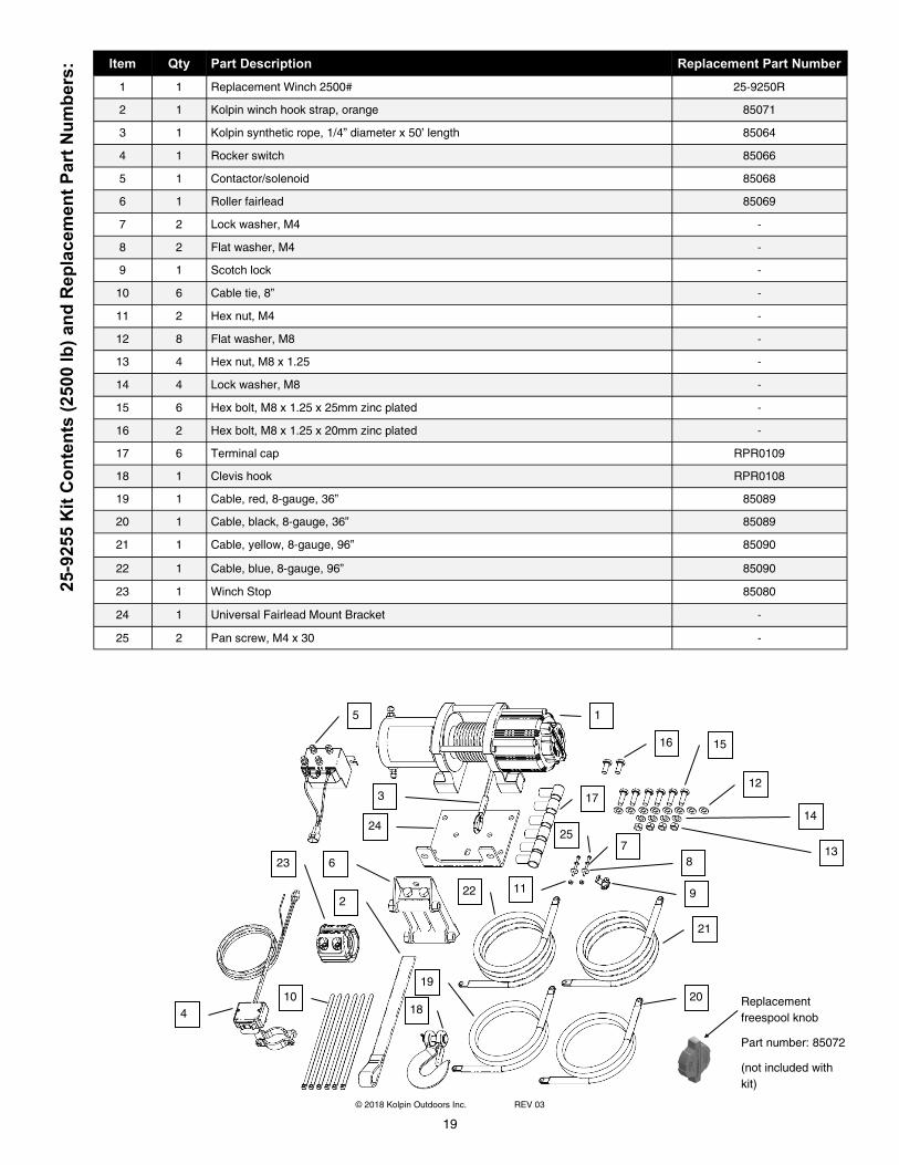
25-9255 Kit Contents (2500 lb) and Replacement Part Numbers: Item Qty Part Description Replacement Part Number
1 1 Replacement Winch 2500# 25-9250R
2 1 Kolpin winch hook strap, orange 85071
3 1 Kolpin synthetic rope, 1/4” diameter x 50’ length 85064
4 1 Rocker switch 85066
5 1 Contactor/solenoid 85068
6 1 Roller fairlead 85069
7 2 Lock washer, M4 -
8 2 Flat washer, M4 -
9 1 Scotch lock -
10 6 Cable tie, 8” -
11 2 Hex nut, M4 -
12 8 Flat washer, M8 -
13 4 Hex nut, M8 x 1.25 -
14 4 Lock washer, M8 -
15 6 Hex bolt, M8 x 1.25 x 25mm zinc plated -
16 2 Hex bolt, M8 x 1.25 x 20mm zinc plated -
17 6 Terminal cap RPR0109
18 1 Clevis hook RPR0108
19 1 Cable, red, 8-gauge, 36” 85089
20 1 Cable, black, 8-gauge, 36” 85089
21 1 Cable, yellow, 8-gauge, 96” 85090
22 1 Cable, blue, 8-gauge, 96” 85090
23 1 Winch Stop 85080
24 1 Universal Fairlead Mount Bracket -
25 2 Pan screw, M4 x 30 -
Replacement
freespool knob
Part number: 85072
(not included with
kit)
16 15
12
14
13
1
21
22
23
3
18
24
5
4
2
6
20
19
17
9
25
11
7
8
10
20
© 2018 Kolpin Outdoors Inc. REV 03
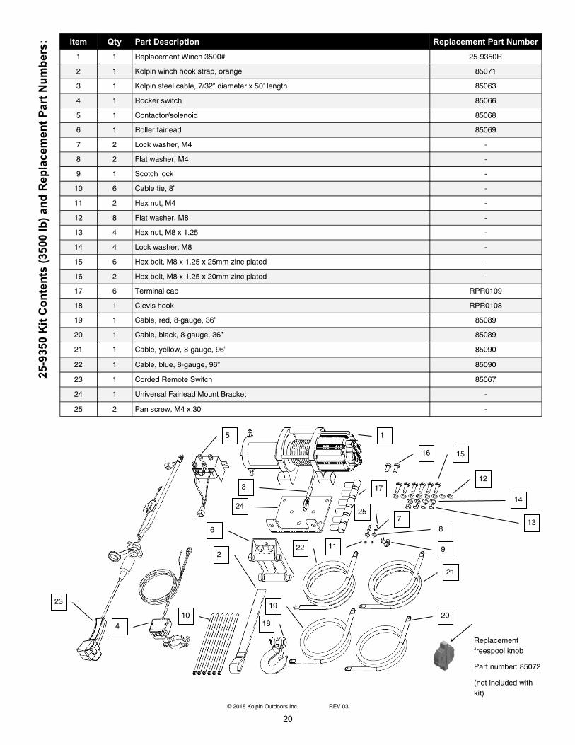
25-9350 Kit Contents (3500 lb) and Replacement Part Numbers: Item Qty Part Description Replacement Part Number
1 1 Replacement Winch 3500# 25-9350R
2 1 Kolpin winch hook strap, orange 85071
3 1 Kolpin steel cable, 7/32” diameter x 50’ length 85063
4 1 Rocker switch 85066
5 1 Contactor/solenoid 85068
6 1 Roller fairlead 85069
7 2 Lock washer, M4 -
8 2 Flat washer, M4 -
9 1 Scotch lock -
10 6 Cable tie, 8” -
11 2 Hex nut, M4 -
12 8 Flat washer, M8 -
13 4 Hex nut, M8 x 1.25 -
14 4 Lock washer, M8 -
15 6 Hex bolt, M8 x 1.25 x 25mm zinc plated -
16 2 Hex bolt, M8 x 1.25 x 20mm zinc plated -
17 6 Terminal cap RPR0109
18 1 Clevis hook RPR0108
19 1 Cable, red, 8-gauge, 36” 85089
20 1 Cable, black, 8-gauge, 36” 85089
21 1 Cable, yellow, 8-gauge, 96” 85090
22 1 Cable, blue, 8-gauge, 96” 85090
24 1 Universal Fairlead Mount Bracket -
25 2 Pan screw, M4 x 30 -
23 1 Corded Remote Switch 85067
Replacement
freespool knob
Part number: 85072
(not included with
kit)
16 15
12
14
13
1
21
22
3
18
24
5
4
2
6
20
19
17
9
25
11
7
8
10
23
21
© 2018 Kolpin Outdoors Inc. REV 03
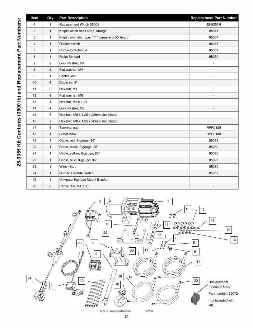
25-9355 Kit Contents (3500 lb) and Replacement Part Numbers: Item Qty Part Description Replacement Part Number
1 1 Replacement Winch 3500# 25-9350R
2 1 Kolpin winch hook strap, orange 85071
3 1 Kolpin synthetic rope, 1/4” diameter x 50’ length 85064
4 1 Rocker switch 85066
5 1 Contactor/solenoid 85068
6 1 Roller fairlead 85069
7 2 Lock washer, M4 -
8 2 Flat washer, M4 -
9 1 Scotch lock -
10 6 Cable tie, 8” -
11 2 Hex nut, M4 -
12 8 Flat washer, M8 -
13 4 Hex nut, M8 x 1.25 -
14 4 Lock washer, M8 -
15 6 Hex bolt, M8 x 1.25 x 25mm zinc plated -
16 2 Hex bolt, M8 x 1.25 x 20mm zinc plated -
17 6 Terminal cap RPR0109
18 1 Clevis hook RPR0108
19 1 Cable, red, 8-gauge, 36” 85089
20 1 Cable, black, 8-gauge, 36” 85089
21 1 Cable, yellow, 8-gauge, 96” 85090
22 1 Cable, blue, 8-gauge, 96” 85090
23 1 Winch Stop 85080
24 1 Corded Remote Switch 85067
25 1 Universal Fairlead Mount Bracket -
26 2 Pan screw, M4 x 30 -
Replacement
freespool knob
Part number: 85072
(not included with
kit)
16 15
12
14
13
1
21
22
23
24
3
18
25
5
4
2
6
20
19
17
9
26
11
7
8
10
22
© 2018 Kolpin Outdoors Inc. REV 03
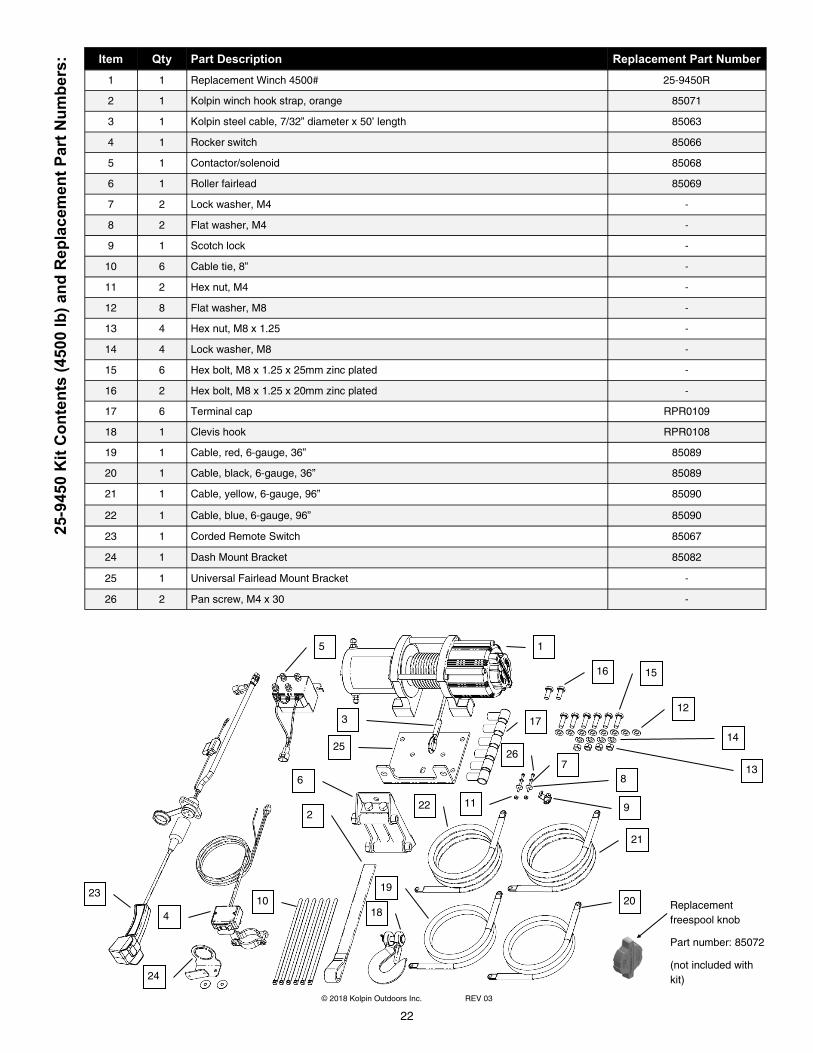
25-9450 Kit Contents (4500 lb) and Replacement Part Numbers: Item Qty Part Description Replacement Part Number
1 1 Replacement Winch 4500# 25-9450R
2 1 Kolpin winch hook strap, orange 85071
3 1 Kolpin steel cable, 7/32” diameter x 50’ length 85063
4 1 Rocker switch 85066
5 1 Contactor/solenoid 85068
6 1 Roller fairlead 85069
7 2 Lock washer, M4 -
8 2 Flat washer, M4 -
9 1 Scotch lock -
10 6 Cable tie, 8” -
11 2 Hex nut, M4 -
12 8 Flat washer, M8 -
13 4 Hex nut, M8 x 1.25 -
14 4 Lock washer, M8 -
15 6 Hex bolt, M8 x 1.25 x 25mm zinc plated -
16 2 Hex bolt, M8 x 1.25 x 20mm zinc plated -
17 6 Terminal cap RPR0109
18 1 Clevis hook RPR0108
19 1 Cable, red, 6-gauge, 36” 85089
20 1 Cable, black, 6-gauge, 36” 85089
21 1 Cable, yellow, 6-gauge, 96” 85090
22 1 Cable, blue, 6-gauge, 96” 85090
23 1 Corded Remote Switch 85067
24 1 Dash Mount Bracket 85082
25 1 Universal Fairlead Mount Bracket -
26 2 Pan screw, M4 x 30 -
Replacement
freespool knob
Part number: 85072
(not included with
kit)
16 15
12
14
13
1
21
22
23
24
3
18
25
5
4
2
6
20
19
17
9
26
11
7
8
10
23
© 2018 Kolpin Outdoors Inc. REV 03
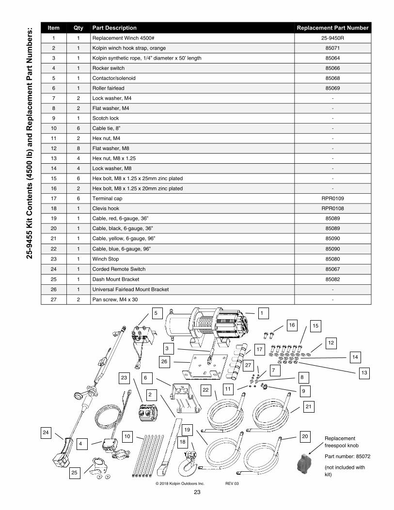
25-9455 Kit Contents (4500 lb) and Replacement Part Numbers: Item Qty Part Description Replacement Part Number
1 1 Replacement Winch 4500# 25-9450R
2 1 Kolpin winch hook strap, orange 85071
3 1 Kolpin synthetic rope, 1/4” diameter x 50’ length 85064
4 1 Rocker switch 85066
5 1 Contactor/solenoid 85068
6 1 Roller fairlead 85069
7 2 Lock washer, M4 -
8 2 Flat washer, M4 -
9 1 Scotch lock -
10 6 Cable tie, 8” -
11 2 Hex nut, M4 -
12 8 Flat washer, M8 -
13 4 Hex nut, M8 x 1.25 -
14 4 Lock washer, M8 -
15 6 Hex bolt, M8 x 1.25 x 25mm zinc plated -
17 6 Terminal cap RPR0109
18 1 Clevis hook RPR0108
19 1 Cable, red, 6-gauge, 36” 85089
20 1 Cable, black, 6-gauge, 36” 85089
21 1 Cable, yellow, 6-gauge, 96” 85090
22 1 Cable, blue, 6-gauge, 96” 85090
16 2 Hex bolt, M8 x 1.25 x 20mm zinc plated -
23 1 Winch Stop 85080
24 1 Corded Remote Switch 85067
25 1 Dash Mount Bracket 85082
26 1 Universal Fairlead Mount Bracket -
27 2 Pan screw, M4 x 30 -
Replacement
freespool knob
Part number: 85072
(not included with
kit)
16 15
12
14
13
1
21
22
23
24
25
3
18
26
5
4
2
6
20
19
17
9
27
11
7
8
10
24
© 2018 Kolpin Outdoors Inc. REV 03
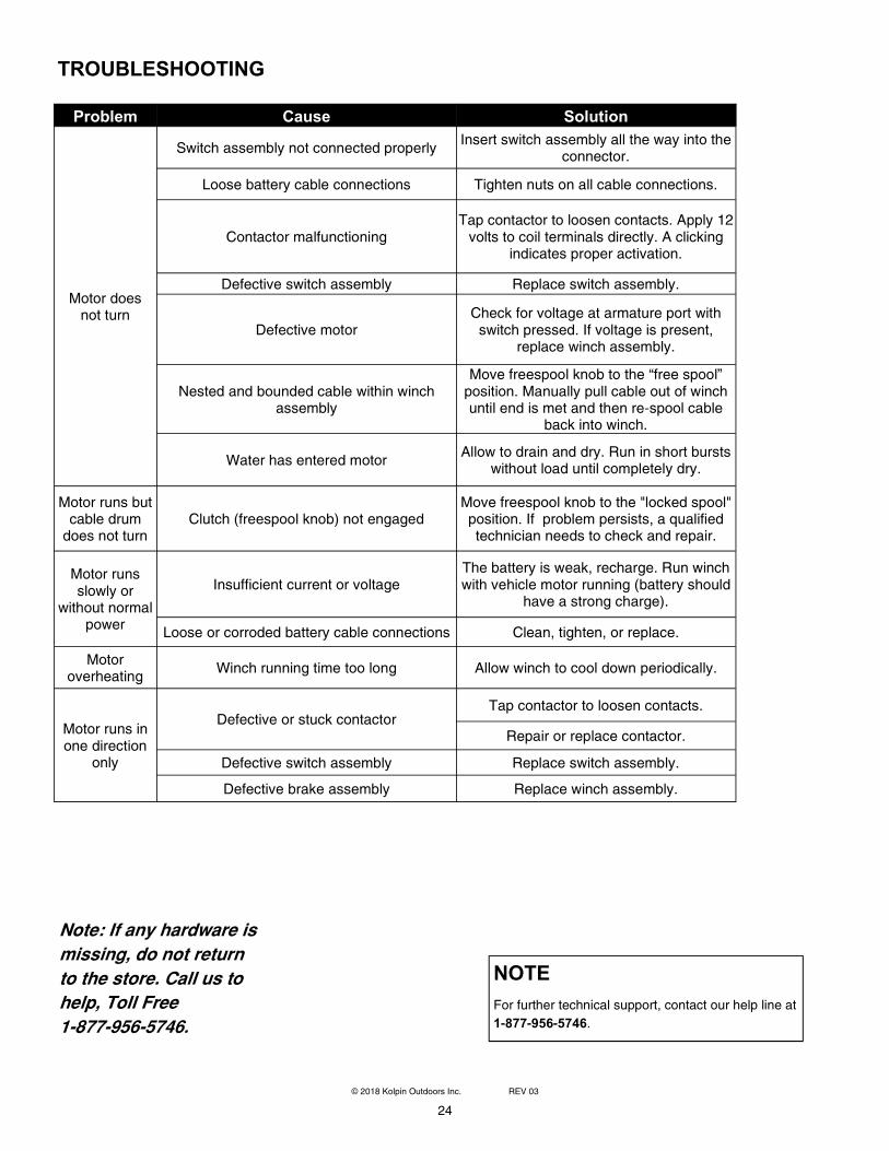
TROUBLESHOOTING
NOTE
For further technical support, contact our help line at
1-877-956-5746.
Problem Cause Solution
Motor does not turn
Switch assembly not connected properly Insert switch assembly all the way into the
connector.
Loose battery cable connections Tighten nuts on all cable connections.
Contactor malfunctioning
Tap contactor to loosen contacts. Apply 12 volts to coil terminals directly. A clicking
indicates proper activation.
Defective switch assembly Replace switch assembly.
Defective motor Check for voltage at armature port with switch pressed. If voltage is present,
replace winch assembly.
Water has entered motor Allow to drain and dry. Run in short bursts
without load until completely dry.
Motor runs but cable drum does not turn
Clutch (freespool knob) not engaged
Move freespool knob to the "locked spool" position. If problem persists, a qualified technician needs to check and repair.
Motor runs slowly or
without normal power
Insufficient current or voltage
The battery is weak, recharge. Run winch with vehicle motor running (battery should
have a strong charge).
Loose or corroded battery cable connections Clean, tighten, or replace.
Motor overheating
Winch running time too long Allow winch to cool down periodically.
Motor runs in one direction
only
Defective or stuck contactor Tap contactor to loosen contacts.
Repair or replace contactor.
Defective switch assembly Replace switch assembly.
Defective brake assembly Replace winch assembly.
Nested and bounded cable within winch assembly
Move freespool knob to the “free spool” position. Manually pull cable out of winch until end is met and then re-spool cable
back into winch.
Note: If any hardware is
missing, do not return
to the store. Call us to
help, Toll Free
1-877-956-5746.

25
© 2018 Kolpin Outdoors Inc. REV 03
Five Year Mechanical Limited Warranty and
Three Year Electrical Limited Warranty
For the period of five (5) years from the purchase date, Kolpin will replace for the original purchaser,
free of charge, any mechanical part or mechanical parts found upon examination by Kolpin to be
defective in material, workmanship, or both. For the period of three (3) years from the purchase
date, Kolpin will replace for the original purchaser, free of charge, any electrical part or electrical
parts found upon examination by Kolpin to be defective in material, workmanship, or both.
All transportation costs incurred submitting product to Kolpin for warranty consideration must be
borne by the purchaser. If Kolpin determines that the product must be returned to the factory for
credit, please call 1-877-956-5746 for a Return Merchandise Authorization (RMA) number and
shipping instructions.
This warranty does not apply to parts that have been damaged by accident, alteration, abuse,
improper maintenance, normal wear, or other causes beyond the manufacturer’s control. In order to
protect you and your ATV, certain parts of the winch/plow system and/or hardware are designed to
fail when the equipment is over-stressed. Parts that are lost due to loosening and improper
maintenance are not covered under warranty. This warranty does not cover removal or reinstallation
labor fees of the winch/plow system and related components.
Peripheral products such as engines, electric motors, and actuators may carry an original
manufacturer’s warranty. Most hardware is general in nature and is easily obtained locally. Be sure
to replace with minimum metric class 8.8 specification.
Kolpin Outdoors, Inc.
Telephone: (763)-478-5800
Toll Free: (877)-956-5746
Fax Number: (800)-245-7569
www.kolpin.com
Email: [email protected]