Embed Size (px)
Citation preview

2
CompaVis™ employs the constant voltage control system that can be controlled not only by APS MLEF LED controllers but also by industry available 24V DC power supplies directly. Overdriven strobing for instantaneous high intensity illumination is also available. The series can support customer’s various image processing environments with a broad range of lighting solutions.
24V DC Driven
Lamp Classification based on IEC standards are applicable to LED lighting units. Criteria for classification is shown above. LEDs are narrow bandwidth light sources with emission levels based on "Blue light, small source" where the wavelength is from 300nm to 700nm. All CompaVis™ Series products are considered to be in either the low risk or exempt group.
LED SAFETY STANDARD (CEI/IEC 62471:2006)
Groups Definition and Emission limit
ExemptNot more than 1.0 W·m-2. Small source defined as one with <0.011 radian.
Low Risk Not more than 1.0 W·m-2
Moderate Risk Not more than 400 W·m-2
High Risk Higher than 400 W·m-2
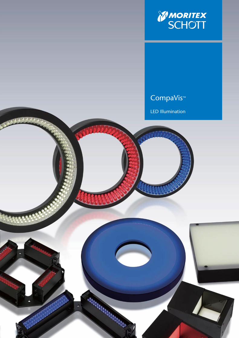
CompaVis™
3
RoHS
CE CE Marking
RoHS Directive
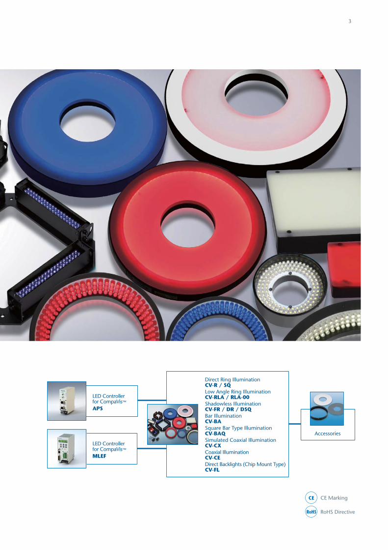
Direct Ring IlluminationCV-R / SQLow Angle Ring IlluminationCV-RLA / RLA-00Shadowless IlluminationCV-FR / DR / DSQBar IlluminationCV-BASquare Bar Type IlluminationCV-BAQSimulated Coaxial IlluminationCV-CXCoaxial IlluminationCV-CEDirect Backlights (Chip Mount Type)CV-FL
Accessories
LED Controller for CompaVis™
APS
LED Controller for CompaVis™
MLEF
4
CompaVis™
CompaVis™ constant voltage control LED illumination products are 24V DC driven and can be controlled by industrial 24V power supplies. Over-driven strobing is also possible for instantaneous, high intensity illumination. This series can be used in various machine vision imaging environments providing a broad range of lighting solutions.
Making obscure and unrecognizable imagesbecome sharp and clear
Broad range of lighting solutions
Our comprehensive system solutions meet a wide range of needs for image processing applications.
Our total system solutions approach provides customers with the best performance & efficiency through consideration of the 3 essential imaging fields of illumination, lens, and peripherals.
SCHOTT MORITEX has the most complete LED illumination portfolio in the industry with the constant current controlled "MG-Wave®" and constant voltage controlled
"CompaVis™ " providing support for the entire range of machine vision customers in various image processing environments.
Image processing total system solutions support
Constant Voltage Control System / 24V DC / Industrial Design with Plastic / Metal Connectors
MG-Wave®
MG-Wave® is our original LED illumination product line designed with our patented highly sophisticated integrated constant current sensing control system that enables our LED controllers to identify the appropriate current value for each individual LED unit connected and control them separately. The constant current design successfully reduces heat generation to improve output intensity, efficiency, and stability.
Constant Current Control System / Extensive Product Variety / Unique, High End Solutions
http://www.schott-moritex.com/english/products/mv/Illumination/mb.html

5
Selection flowchart
CompaVis™
MG-Wave®
24V DC Driven 24V DC Input
*Refer to Machine Vision General Catalog “Lens”
100-240V AC Input Analog & Digital Controllers with External Control
1-ch, 2-ch, & 4-ch models available; 3-ch available for MCEP Series
LED Lineup Reference Table
Direct Ring IlluminationLow Angle Ring IlluminationShadowless IlluminationBar IlluminationHigh Power Bar IlluminationSquare Bar Type IlluminationDome IlluminationSimulated Coaxial IlluminationDirect Backlights (Chip Mount Type)Direct Backlights (Discrete Type)Edge Type BacklightsCollimated BacklightsHigh Brightness LED Light LineDiffuse Chip Type Bar Illumination
Coaxial IlluminationHigh Power LED Spot Illumination
LED Spot ProjectorsIR IlluminationUV IlluminationVariable Color RGB Illumination
LED Controller Lineup Reference
Analog LED Controllersfor CompaVis™
24V DC, DIN rail mountable
Constant current sensingcontrol system
LED Controllersfor MG-Wave®
For high power LED spotillumination
LED Controllersfor MCEP/MSPP Series
Applicable lighting length:840-2880mm
LED Controllersfor MLNX Series
EthernetDigital (Pararell/8bit)
Analog (0-5V)Digital (Pararell/8bit)
DC24V
AC100V~240V
CompaVis™
MG-Wave®
CompaVis™
MG-Wave®
2ch
1ch, 2ch, 4ch
CompaVis™
MG-Wave®
ExternalControl
Input
Channel
Identifyobject& FOV
Select camera,lens, and
peripherals
Choose LEDconfiguration,
type, andwavelength
Choose LEDcontroller
(i.e. drive method)
Test systemfor proof
of concept
Completesetup
Controlled by proprietary APS LED controllers as well as other available industrial 24V power suppliers. Over-driven strobing and branched connection also available.
More than 350 models with low heatgeneration and high luminance efficiency
Extensive Product Variety
MLEF Series Digital LED Controllersfor CompaVis™
For CompaVis™
24V DC, DIN rail mountable
Digital LED controller with external controlAnalog LED controller without external control
MDRLMLRL
MSRL/MSLL/MSQLMBRLMHBCMDQL
MSDC/MDMLMSCL
MDBC/MQFCMDBL
MEBL/MEBCMCBP
MLNC/MLNX/HB-LED-LLMBRC
MCEC/MCEL
MCEP
MSPPIRIRUV
RGB
CV-R/SQCV-RLA/RLA-00
CV-FR/DR/DSQCV-BA
CV-BAQ
CV-CX
CV-CE
CV-FL
CompaVis™ Series MG-Wave® SeriesIllumination Type
Direct Ring Illumination
CV-R/SQ Series
6
Illumination Structure
• High intensity, uniform direct, bright-fi eld 360-degree lighting
• Standard LED illumination for a wide range of applications
• Standard LED Illumination for a wide range of application
Direct Ring Illumination: CV-R Series
Square Ring Illumination: CV-SQ Series
RoHS CE
CV-R Series
CV-SQ Series
Camera
Lens
Object
Lens
Object
CV-R Series CV-SQ Series
InternalDiameter
CV-SQ - X X
External Dimensions
Length Width
CV-R - -X
ExternalDiameter
InternalDiameter
LightingAngle
EmittedColor Connector
: Red: Blue: White
RBW
: JST SMR-03V-B: M12 male
non -M12
EmittedColor Connector
: Red: Blue: White
RBW
: JST SMR-03V-B: M12 male
non -M12
Explanation of Model CodeModel Emitted
ColorPower(W)
External Dimensions (mm) Lighting Angle(Deg.)
Weight(g) * Accessories
External Diameter
Internal Diameter Height
CV-R-32X10-70R Red 0.9 32 10 16 70 35 CV-AD-R-32X10-70CV-DF-R-32X10-70CV-PL-R-32X10-70
CV-R-32X10-70B Blue 1.7 32 10 16 70 35
CV-R-32X10-70W White 1.7 32 10 16 70 35
CV-R-42X18-65R Red 1.5 42 18 18 65 55 CV-AD-R-42X18-65CV-DF-R-42X18-65CV-PL-R-42X18-65
CV-R-42X18-65B Blue 2.7 42 18 18 65 55
CV-R-42X18-65W White 2.7 42 18 18 65 55
CV-R-50X28-75R Red 0.7 50 28 16 75 55 CV-AD-R-50X28-75CV-DF-R-50X28-75CV-PL-R-50X28-75
CV-R-50X28-75B Blue 2.6 50 28 16 75 55
CV-R-50X28-75W White 2.8 50 28 16 75 55
CV-R-70X35-90R Red 1.5 70 35 22 90 140 CV-AD-R-70X35-90CV-DF-R-70X35-90CV-PL-R-70X35-90
CV-R-70X35-90B Blue 5.5 70 35 22 90 140
CV-R-70X35-90W White 5.5 70 35 22 90 140
CV-R-90X30-80R Red 5.3 90 30 20 83 260 CV-AD-R-90X30-80CV-DF-R-90X30-80CV-PL-R-90X30-80
CV-R-90X30-80B Blue 9.3 90 30 20 83 260
CV-R-90X30-80W White 10.3 90 30 20 83 260
CV-R-90X50-70R Red 3.5 90 50 20 71 180 CV-AD-R-90X50-70CV-DF-R-90X50-70CV-PL-R-90X50-70
CV-R-90X50-70B Blue 6.2 90 50 20 71 180
CV-R-90X50-70W White 6.4 90 50 20 71 180
CV-R-120X58-50R Red 3.1 120 58 31.5 52 560 CV-AD-R-120X58-50CV-DF-R-120X58-50CV-PL-R-120X58-50
CV-R-120X58-50B Blue 13.1 120 58 31.5 52 560
CV-R-120X58-50W White 13.5 120 58 31.5 52 560
Model Emitted Color
Power(W)
External Dimensions (mm)Weight
(g) * AccessoriesLength Width Height Internal
Diameter
CV-SQ-56X56X30R Red 1.0 56 56 18 30 85 CV-DF-SQ-56X56X30CV-PL-SQ-56X56X30
CV-SQ-56X56X30B Blue 2.5 56 56 18 30 85
CV-SQ-56X56X30W White 2.6 56 56 18 30 85
* It is weighted 15g more in case "M12".
7
Light Distribution Characteristics
CV-R-32X10-70R (B,W)
CV-R-70X35-90R (B,W)
CV-R-120X58-50R (B,W)
CV-R-42X18-65R (B,W)
CV-R-90X30-80R (B,W)
CV-SQ-56X56X30R (B,W)
CV-R-50X28-75R (B,W)
CV-R-90X50-70R (B,W)
4-M3x4mm DepthPCD 28 Equidistribution
Cable Label
ø18
ø4
18
ø42 500
45°
65°
4-M3x4mm DepthPCD 40 Equidistribution
Cable Label
ø28
ø4
16
ø50 500
75°
4-M3x4mm DepthPCD 50
Cable Label
ø35
ø4
22
ø70 500
4-M3x4mm DepthPCD 70 Equidistribution
Cable Label
ø4
20
500
ø50
ø90
45°
71°
SECTION B-B
31.5
0
ø58ø120
B
B500
90°
38°
45°
Equidistribution PCD 904-M3 4
ø30
4-M3x3mm Mounting Hole
Cable Label
3856
3856
ø4
18
500
SECTION A-A
16
70°
Cable Label
ø4
500
ø10
ø32
45°
A
A
4-M3 4
4-M3x4mm DepthPCD 70 Equidistribution
Cable Label
20
500
ø30
ø90
83°
45°
0.6
0.7
0.8
0.9
1.0
0.5
0.4
0.3
0.2
0.1
0.0
WD=30 WD=20 WD=10
Distance in X-axis
Parallel to X-axis(Horizontal Direction)
Rela
tive
Inte
nsity
CV-R-50X28-75W
WD=0
-60-70 -50 -40 -30 -20 -10 0 10 20 30 40 50 60 70
Parallel to X-axis(Horizontal Direction)
Rela
tive
Inte
nsity
CV-R-70X35-90W
WD=30 WD=20 WD=10
Distance in X-axisWD=0
-60-70 -50 -40 -30 -20 -10 0 10 20 30 40 50 60 700.0
0.2
0.4
0.6
0.8
1.0
1.2Parallel to X-axis(Horizontal Direction)
Rela
tive
Inte
nsity
CV-R-90X30-80W
WD=35 WD=25 WD=10 WD=0
Distance in X-axis-60-70 -50 -40 -30 -20 -10 0 10 20 30 40 50 60 70
0.0
0.2
0.4
0.6
0.8
1.0
1.2
Parallel to X-axis(Horizontal Direction)
Rela
tive
Inte
nsity
CV-R-120X58-50W
Distance in X-axisWD=40 WD=30 WD=20 WD=0
0.6
0.7
0.8
0.9
1.0
0.5
0.4
0.3
0.2
0.1
0.0-60-70 -50 -40 -30 -20 -10 0 10 20 30 40 50 60 70
Parallel to X-axis(Horizontal Direction)
Rela
tive
Inte
nsity
WD=20 WD=10 WD=5 WD=0Distance in X-axis
-60-70 -50 -40 -30 -20 -10 0 10 20 30 40 50 60 700.0
0.2
0.4
0.6
0.8
1.0
1.2CV-SQ-56X56X30W
8
Applications
Sample Images
Accessories
Adapter Diffusion Plate Polarizer Plate
CV-AD-Rxx Used to mount the diffuser or polarizer onto the LED lighting.
CV-DF-Rxx To be mounted in front of the LED lighting using the adapter. Used to soften the lighting output, so as to reduce the glares on specular surface.
CV-PL-Rxx To be mounted in front of the LED lighting using the adapter. Used together with a Polarizer fi lter lens in front of the camera as a set. It helps to reduce glare.
Foreign Object in Paper Cup PCB Fabrication Inspection Not Much Light at Short WD Full Light at Longer WD
CV-R Series CV-SQ Series
• Lead frame inspection
• Electronic component appearance inspection
• QFP/SOP lead curve inspection
• Transparency fi lm dirt inspection
• Various types of silhouette observation
Low Angle Ring Illumination
CV-RLA/RLA-00 Series
9
• Refl ection can be minimized by the low-angle, dark-fi eld lighting confi guration
• Ideal for imaging of uneven surfaces, eg. Embossment and surface fl aw detection
• Indirect, horizontal 360-degree inner diameter illumination
• Used at a short WD to the test object
Low Angle Ring Illumination: CV-RLA Series
Zero Angle Ring Illumination: CV-RLA-00 Series
RoHS CE
CV-RLA - -X
ExternalDiameter
InternalDiameter
LightingAngle
EmittedColor Connector
: Red: Blue: White
RBW
: JST SMR-03V-B: M12 male
non -M12
Explanation of Model Code
Model Emitted Color
Power(W)
External Dimensions (mm) Lighting Angle(Deg.)
Weight(g) * Accessories
External Diameter
Internal Diameter Height
CV-RLA-74X48-30R Red 2.2 74 48 19 30 95 CV-DF-RLA-74X48-30
CV-RLA-74X48-30B Blue 5.6 74 48 19 30 95
CV-RLA-74X48-30W White 5.3 74 48 19 30 95
CV-RLA-100X70-30R Red 1.8 100 70 22 30 170 CV-DF-RLA-100X70-30
CV-RLA-100X70-30B Blue 8.7 100 70 22 30 170
CV-RLA-100X70-30W White 8.4 100 70 22 30 170
CV-RLA-132X96-15R Red 2.5 132 96 22 15 280 CV-DF-RLA-132X96-15
CV-RLA-132X96-15B Blue 7.1 132 96 22 15 280
CV-RLA-132X96-15W White 7.2 132 96 22 15 280
Model Emitted Color
Power(W)
External Dimensions (mm) Lighting Angle(Deg.)
Weight(g) * Accessories
External Diameter
Internal Diameter Height
CV-RLA-75X46-00R Red 0.5 75 46 10 0 70
CV-RLA-75X46-00B Blue 2.5 75 46 10 0 70
CV-RLA-75X46-00W White 2.8 75 46 10 0 70
CV-RLA-96X60-00R Red 0.7 96 60 10 0 110
CV-RLA-96X60-00B Blue 3.1 96 60 10 0 110
CV-RLA-96X60-00W White 3.5 96 60 10 0 110
CV-RLA-200X170-00R Red 2.0 200 170 10 0 160
CV-RLA-200X170-00B Blue 5.9 200 170 10 0 160
CV-RLA-200X170-00W White 6.1 200 170 10 0 160
* It is weighted 15g more in case "M12".
Illumination Structure
CV-RLA Series
Camera
Lens
Object
Illuminating the Object from a Low Position
CV-RLA-00 Series
Object
Camera
Lens
Light Distribution Characteristics
10
4-M3x4mm DepthPCD 60 Equidistribution
Cable Label
ø48
ø74
ø4
500
19
45°
30°
ø200ø170
500
4-M3192 4
10
45°
CV-RLA-74X48-30W
WD=30 WD=20 WD=10 WD=0
Parallel to X-axis(Horizontal Direction)
Distance in X-axis-60-70 -50 -40 -30 -20 -10 0 10 20 30 40 50 60 70
Rela
tive
Inte
nsity
0.6
0.7
0.8
0.9
1.0
0.5
0.4
0.3
0.2
0.1
CV-RLA-200X170-00W
WD=20 WD=10 WD=5 WD=0
Parallel to X-axis(Horizontal Direction)
Rela
tive
Inte
nsity
Distance in X-axis-60-70 -50 -40 -30 -20 -10 0 10 20 30 40 50 60 70
0.0
0.2
0.4
0.6
0.8
1.0
1.2
CV-RLA-74X48-30R (B,W)
CV-RLA-200X170-00R (B,W)
4-M3x4mm DepthPCD 84 Equidistribution
Cable Label
ø70
ø100 500
ø4
2230°
45°
CV-RLA-100X70-30R (B,W)4-M3x4mm DepthPCD 116 Equidistribution
Cable Label
ø96
ø132 500
ø4
22
45°
15°
CV-RLA-132X96-15R (B,W)
Equal Distribution
ø46
PCD ø56
ø75 500
10
4-M4 4
CV-RLA-75X46-00R (B,W)
45°
ø80ø60
ø96 500
10
4-M4 4
CV-RLA-96X60-00R (B,W)
CV-RLA-75X46-00W
WD=15 WD=20 WD=25 WD=35
Parallel to X-axis(Horizontal Direction)
Distance in X-axis-60-70 -50 -40 -30 -20 -10 0 10 20 30 40 50 60 70
Rela
tive
Inte
nsity
0.1
0.0
0.2
0.3
0.4
0.5
0.6
0.7
0.8
0.9Parallel to X-axis(Horizontal Direction)
CV-RLA-96X60-00W
WD=15 WD=10 WD=5 WD=0
Rela
tive
Inte
nsity
Distance in X-axis-60-70 -50 -40 -30 -20 -10 0 10 20 30 40 50 60 70
0.0
0.2
0.4
0.6
0.8
1.0
1.2
CV-RLA-100X70-30W
WD=30 WD=20 WD=10 WD=0
Parallel to X-axis(Horizontal Direction)
Rela
tive
Inte
nsity
Distance in X-axis-60-70 -50 -40 -30 -20 -10 0 10 20 30 40 50 60 70
0.0
0.2
0.4
0.6
0.8
1.0
1.2CV-RLA-132X96-15W
WD=40 WD=25 WD=15 WD=0
Parallel to X-axis(Horizontal Direction)
Rela
tive
Inte
nsity
Distance in X-axis-60-70 -50 -40 -30 -20 -10 0 10 20 30 40 50 60 70
0.0
0.2
0.4
0.6
0.8
1.0
1.2
11
Sample Images
CV-RLA Series CV-RLA-00 Series
Chamfer Checking on Metal Ring 12-Pin Connector Scratch on Glass Plate CD Imprint Inspection
Accessories
CV-DF-RLAxx
Used to create a relatively non-directional light.
Reducing glare on specular surfaces. Easily mount
onto a Low-Angle Ring Illumination.
Diffusion Ring
Applications
• Substrate and PCB positioning
• Chip component inspection
• LCD alignment
• Plastic container inspection
• Label inspection
• Mounter
• IC marking inspection, etc.
Shadowless Illumination
CV-FR/DR/DSQ Series
12
RoHS CE
• Diffuse, shadowless illumination*
• Optimal soft, uniform light for shiny surfaces
Shadowless Ring Illumination: CV-FR Series
• Shallow angle LED illumination that provides diffused, soft light
• Ideal for fl aw or edge detection on refl ective surfaces
Shadowless Low Angle Ring Illumination: CV-DR Series
• Diffused illumination best suited for square shape objects, such as in BGA & QFP applications
Square Shadowless Low Angle Illumination: CV-DSQ Series
Object
Camera
Lens
Illumination Structure
Object
Camera
Lens
Object
Camera
Lens
CV-DR SeriesCV-FR Series CV-DSQ Series
-CV-FR X
ExternalDiameter
InternalDiameter
EmittedColor
-CV-DR X
ExternalDiameter
InternalDiameter
EmittedColor Connector
: Red: Blue: White
RBW
: JST SMR-03V-B: M12 male
non -M12
- -CV-DSQ X
EmittedColor
: Red: Blue: White
RBW
Connector
: JST SMR-03V-B: M12 male
non -M12
Connector
: Red: Blue: White
RBW
: JST SMR-03V-B: M12 male
non -M12
External Dimensions
Length WidthHeight of
Lighting Surface
FR Series
DR Series
Explanation of Model Code
13
Model Emitted Color
Power(W)
External Dimensions (mm) Emitting Area Dimensions (mm)Weight
(g) *External Diameter
Internal Diameter Height Inside
Square Length Width Height
CV-DSQ-48X48-15R Red 0.4 48 48 30 10 / 26 36 36 15 110
CV-DSQ-48X48-15B Blue 1.0 48 48 30 10 / 26 36 36 15 110
CV-DSQ-48X48-15W White 1.1 48 48 30 10 / 26 36 36 15 110
CV-DSQ-75X75-15R Red 0.7 75 75 30 20 / 53 64 64 15 180
CV-DSQ-75X75-15B Blue 2.6 75 75 30 20 / 53 64 64 15 180
CV-DSQ-75X75-15W White 3.0 75 75 30 20 / 53 64 64 15 180
CV-DSQ-96X96-15R Red 0.9 96 96 30 74 84 84 15 190
CV-DSQ-96X96-15B Blue 3.8 96 96 30 74 84 84 15 190
CV-DSQ-96X96-15W White 2.6 96 96 30 74 84 84 15 190
CV-DSQ-120X120-15R Red 1.1 120 120 30 98 108 108 15 240
CV-DSQ-120X120-15B Blue 5.2 120 120 30 98 108 108 15 240
CV-DSQ-120X120-15W White 6.0 120 120 30 98 108 108 15 240
* It is weighted 15g more in case "M12".
Model Emitted Color
Power(W)
External Dimensions (mm) Emitting Diameter
(mm)
Weight(g) *External
Diameter Internal
Diameter Height
CV-FR-102X33R Red 1.2 102 33 12 80 190
CV-FR-102X33B Blue 3.3 102 33 12 80 190
CV-FR-102X33W White 3.2 102 33 12 80 190
CV-FR-125X44R Red 2.3 125 44 12 102.5 280
CV-FR-125X44B Blue 3.8 125 44 12 102.5 280
CV-FR-125X44W White 4.0 125 44 12 102.5 280
Model Emitted Color
Power(W)
External Dimensions (mm) Emitting Diameter
(mm)
Weight(g) *External
Diameter Internal
Diameter Height
CV-DR-100X73R Red 1.7 100 73 40 93.5 230
CV-DR-100X73B Blue 5.0 100 73 40 93.5 230
CV-DR-100X73W White 5.8 100 73 40 93.5 230
CV-DR-136X109R Red 1.7 136 109 40 129.5 340
CV-DR-136X109B Blue 8.6 136 109 40 129.5 340
CV-DR-136X109W White 8.4 136 109 40 129.5 340
CV-DR-180X153R Red 2.3 180 153 40 173.5 420
CV-DR-180X153B Blue 10.3 180 153 40 173.5 420
CV-DR-180X153W White 11.6 180 153 40 173.5 420
14
4-M3x4mm DepthPCD 70 Equidistribution
Cable Label
ø33
ø102 500
12
ø445°
4-M3x4mm DepthPCD 70 Equidistribution
Cable Label
ø44
ø125 500
12
4-M3x4mm DepthPCD 120 Equidistribution
Cable Label
ø109
ø136 500
40
ø4
ø84
ø73
ø100
40
4 -M3 4Equal Distribution
500
ø164ø153
ø180
40
4 -M3 4Equal Distribution
500
ø4
4 -M3 3
50048
30
48 26 1030
2610
3048
36 (Lighting Area)
36 (
Ligh
ting
Are
a)
ø430
75
4
500
20
57
205775
53
53
4-M3x4mmTap Depth
63 (Lighting Area)
63 (
Ligh
ting
Are
a)
ø4
96
30 4
500
747896
7874 4-M3x4mm Tap Depth
84 (Lighting Area)
15 (
Ligh
ting
Are
a)
ø4
30
120
4
500
98
98
102
102
4-M3x4mm Tap Depth
120
108 (Lighting Area)
15 (
Ligh
ting
Are
a)
CV-FR-102X33R (B,W)
CV-DR-136X109R (B,W)
CV-DSQ-75X75-15R (B,W)
CV-FR-125X44R (B,W)
CV-DR-180X153R (B,W)
CV-DSQ-96X96-15R (B,W)
CV-DR-100X73R (B,W)
CV-DSQ-48X48-15R (B,W)
CV-DSQ-120X120-15R (B,W)
15
Light Distribution Characteristics
Sample Images
CV-FR Series CV-DR Series
CV-DSQ Series
Cap Inspection Silkscreen Printing Verifi cation for Remote Control
CD Inspection OCR on Brushed Metal Surface
Connector Inspection Ink Cartridge Print Head Inspection
Parallel to X-axis(Horizontal Direction)
Rela
tive
Inte
nsity
CV-FR102X33W
WD=25 WD=20WD=30
Distance in X-axis-60-70 -50 -40 -30 -20 -10 0 10 20 30 40 50 60 70
0.0
0.1
0.2
0.3
0.4
0.5
0.6
0.7Parallel to X-axis(Horizontal Direction)
Rela
tive
Inte
nsity
CV-FR125X44W
WD=30 WD=10WD=40
Distance in X-axis-60-70 -50 -40 -30 -20 -10 0 10 20 30 40 50 60 70
0.0
0.1
0.2
0.3
0.4
0.5
0.6
0.7
0.8
0.9
Parallel to X-axis(Horizontal Direction)
CV-DR-100X73W
WD=35 WD=25 WD=10 WD=0Distance in X-axis
-60-70 -50 -40 -30 -20 -10 0 10 20 30 40 50 60 70
Rela
tive
Inte
nsity
0.0
0.2
0.4
0.6
0.8
1.0
1.2Parallel to X-axis(Horizontal Direction)
CV-DR-136X109W
WD=50 WD=30 WD=10 WD=0
Distance in X-axis-60-70 -50 -40 -30 -20 -10 0 10 20 30 40 50 60 70
Rela
tive
Inte
nsity
0.0
0.2
0.4
0.6
0.8
1.0
1.2CV-DR-180X153W
WD=100 WD=90 WD=70 WD=50
Parallel to X-axis(Horizontal Direction)
Distance in X-axis-60-70 -50 -40 -30 -20 -10 0 10 20 30 40 50 60 70
Rela
tive
Inte
nsity
0.0
0.2
0.4
0.6
0.8
1.0
1.2
Bar Illumination
CV-BA Series
16
Model Emitted Color
Power(W)
External Dimensions (mm)
Emitting Area Dimensions
(mm) Weight(g) * Accessories
Length Width Height Length Width
CV-BA-42X15R Red 0.8 52 17 21.5 42 15 35CV-DF-BA-42X15CV-PL-BA-42X15
CV-BA-42X15B Blue 1.4 52 17 21.5 42 15 35
CV-BA-42X15W White 1.5 52 17 21.5 42 15 35
CV-BA-74X27R Red 1.8 86 29 18.5 74 27 110CV-DF-BA-74X27CV-PL-BA-74X27
CV-BA-74X27B Blue 3.9 86 29 18.5 74 27 110
CV-BA-74X27W White 3.8 86 29 18.5 74 27 110
CV-BA-82X15R Red 0.7 92 17 21.5 82 15 45CV-DF-BA-82X15CV-PL-BA-82X15
CV-BA-82X15B Blue 2.8 92 17 21.5 82 15 45
CV-BA-82X15W White 2.7 92 17 21.5 82 15 45
CV-BA-130X15R Red 1.0 140 17 21.5 130 15 65 CV-DF-BA-130X15CV-PL-BA-130X15CV-SP-BA-130X15
CV-BA-130X15B Blue 4.5 140 17 21.5 130 15 65
CV-BA-130X15W White 4.4 140 17 21.5 130 15 65
CV-BA-200X15R Red 1.7 204 17 21.5 194 15 80 CV-DF-BA-200X15CV-PL-BA-200X15CV-SP-BA-200X15
CV-BA-200X15B Blue 6.8 204 17 21.5 194 15 80
CV-BA-200X15W White 7.2 204 17 21.5 194 15 80
* It is weighted 15g more in case "M12".
• High-intensity LED block array
• Can be directed at any angle to the surface for either direct brightfi eld or optimal oblique darkfi eld lighting
RoHS CE
CV-BA- X
Lighting Area Dimensions
Length WidthEmittedColor Connector
: Red: Blue: White
RBW
: JST SMR-03V-B: M12 male
non -M12
Explanation of Model Code
Character on Flexible Ribbon Cable Silkscreen Printing on Faceplate
Sample Images
Camera
Lens
Object
Illumination Structure
17
Accessories
CV-DF-BAxxx
To be mounted in front of the LED lighting using screws provided. Used to soften the lighting output, so as to reduce the glares on specular surface.
CV-PL-BAxxx
To be mounted in front of the LED lighting using screws provided.Used together with a polarizer fi lter lens in front of the camera as a set. It helps to reduce glare.
Diffusion Plate Polarizer
CV-BA-42X15W
WD=30 WD=20 WD=10 WD=0
Parallel to X-axis(Horizontal Direction)
Rela
tive
Inte
nsity
Distance in X-axis-60-70 -50 -40 -30 -20 -10 0 10 20 30 40 50 60 70
0.0
0.2
0.4
0.6
0.8
1.0
1.2CV-BA-74X27W
WD=35 WD=25 WD=10 WD=0
Parallel to X-axis(Horizontal Direction)
Rela
tive
Inte
nsity
Distance in X-axis-60-70 -50 -40 -30 -20 -10 0 10 20 30 40 50 60 70
0.0
0.2
0.4
0.6
0.8
1.0
1.2CV-BA-82X15W
WD=35 WD=20 WD=10 WD=0
Parallel to X-axis(Horizontal Direction)
Distance in X-axis-60-70 -50 -40 -30 -20 -10 0 10 20 30 40 50 60 70
Rela
tive
Inte
nsity
0.1
0.0
0.2
0.3
0.4
0.5
0.6
0.7
0.8
0.9
CV-BA-130X15W
WD=30 WD=20 WD=10 WD=0
Parallel to X-axis(Horizontal Direction)
Rela
tive
Inte
nsity
Distance in X-axis-60-70 -50 -40 -30 -20 -10 0 10 20 30 40 50 60 70
0.0
0.2
0.4
0.6
0.8
1.0
1.2CV-BA-200X15W
WD=50 WD=30 WD=10 WD=0
Parallel to X-axis(Horizontal Direction)
Distance in X-axis-60-70 -50 -40 -30 -20 -10 0 10 20 30 40 50 60 70
Rela
tive
Inte
nsity
0.1
0.0
0.2
0.3
0.4
0.5
0.6
0.7
0.8
0.9
42(Lighting Area)
2-M3x3mm Depth
15(L
ight
ing
Area
)
Cable Label
4-M2x4mm Depth(Including Opposite Face)
5.5
21.5
17
9
500
10
52
22
ø4
74(Lighting Area)
27(L
ight
ing
Area
)
2-M3x4mm Depth
Cable Label
18.5
29
500
86
50
ø4
82(Lighting Area)
2-M3x4mm Depth
15(L
ight
ing
Area
)
Cable Label
2-M2x4mm Depth
4-M2x4mm Depth(Including Opposite Face)
21.5
17
500
87
62
92
ø4
5.5
9
130(Lighting Area)
2-M3x4mm Depth
15(L
ight
ing
Area
)
Cable Label
4-M2x4mm Depth(Including Opposite Face)
21.5
17
5.5
9
500
140
110
ø4
CV-BA-42X15R (B,W)
CV-BA-130X15R (B,W)
CV-BA-74X27R (B,W)
CV-BA-200X15R (B,W)
CV-BA-82X15R (B,W)
Light Distribution Characteristics
194(Lighting Area)
2-M2x4mm Mounting Hole
2-M2x4mm Mounting Hole
2-M2x4mmMounting Hole
15(L
ight
ing
Area
)
500
21.5
15
17
204174
ø4
Applications
• IC marking inspection, inspection of components on glass substrates
• Dirt inspection on cap sides and inside surfaces• Wafer appearance inspection• Solder inspection and connector pitch inspection• Inspection, etc. of BGA, QFP, etc.
18
Square Bar Type Illumination
CV-BAQ Series
Work
Camera
Lens
Sample Images
QFP Solder Inspection SSOP Pre-cut IC Package Inspection
Illumination Structure
• Four high-intensity bar LED arrangement
• Optimal direct brightfi eld or oblique darkfi eld lighting from adjustable angles
• Can be controlled independently
RoHS CE
CV-BAQ - X
External Dimensions
Length WidthEmittedColor Connector
: Red: Blue: White
RBW
: JST SMR-03V-B: M12 male
non -M12
Explanation of Model Code
Model Emitted Color
Power(W)
External Dimensions (mm)Emitting Area Dimensions
(mm) Weight(g) * Accessories
Length Width Height Inside Square Length Width
CV-BAQ-108X108R Red 3.1 108 108 30 60 42 15 220
CV-DF-BA-42X15CV-BAQ-108X108B Blue 5.7 108 108 30 60 42 15 220
CV-BAQ-108X108W White 6.0 108 108 30 60 42 15 220
CV-BAQ-148X148R Red 2.6 148 148 30 100 82 15 290
CV-DF-BA-82X15CV-BAQ-148X148B Blue 11.3 148 148 30 100 82 15 290
CV-BAQ-148X148W White 10.9 148 148 30 100 82 15 290
CV-BAQ-200X200R Red 4.1 200 200 30 152 130 15 390
CV-DF-BA-130X15CV-BAQ-200X200B Blue 18.1 200 200 30 152 130 15 390
CV-BAQ-200X200W White 17.5 200 200 30 152 130 15 390
* It is weighted 60g more in case "M12".
19
Accessories
CV-DF-BAxxx
To be mounted in front of the LED lighting using the screws provided. Used to soften the lighting output, so as to reduce the glare on specular surface.
Diffuser
CV-BAQ-108X108W
WD=50 WD=20 WD=10 WD=0
Parallel to X-axis(Horizontal Direction)
Rela
tive
Inte
nsity
Distance in X-axis-60-70 -50 -40 -30 -20 -10 0 10 20 30 40 50 60 70
0.0
0.2
0.4
0.6
0.8
1.0
1.2CV-BAQ-148X148W
WD=80 WD=60 WD=40 WD=20
Parallel to X-axis(Horizontal Direction)
Rela
tive
Inte
nsity
Distance in X-axis-60-70 -50 -40 -30 -20 -10 0 10 20 30 40 50 60 70
0.0
0.2
0.4
0.6
0.8
1.0
1.2CV-BAQ-200X200W
WD=80 WD=60 WD=40 WD=120
Parallel to X-axis(Horizontal Direction)
Distance in X-axis-60-70 -50 -40 -30 -20 -10 0 10 20 30 40 50 60 70
Rela
tive
Inte
nsity
0.6
0.7
0.8
0.9
1.0
0.5
0.4
0.3
0.2
0.1
0.0
4-42(Lighting Area) 4-M4
Mounting Hole
4-15(Lighting Area)
Cable Label6070
108
6070108
500
30
ø4
4-82(Lighting Area)
4-M4Mounting Hole
4-15(Lighting Area)
Cable Label
100110
148 500
100
110
148
30
ø4
4-130(Lighting Area)
4-15(Lighting Area)
4-M4 Through
Cable Label
162200
152
152
162
200
500
30
ø4
CV-BAQ-108X108R (B,W)
CV-BAQ-200X200R (B,W)
CV-BAQ-148X148R (B,W)
Light Distribution Characteristics
Compact coaxial LED that only requires
minimal installation space.
• Fully compatible with our MML Series telecentric lenses that set the industry standard for coaxial illumination, these LEDs are a perfect match
• Body design has been miniaturized and this series is even smaller than its compact predecessors
• L-shaped (right angle) illumination cable design enables further space savings
20
Coaxial Illumination
CV-CE Series
CV-CE-14X8
EmittedColor Connector
: Red: Blue: White
RBW
: JST SMR-03V-B: M12 male
non -M12
Explanation of Model Code
Model Emitted Color
Power(W)
External Dimensions (mm)Emitting Diameter
(mm)
Weight(g) *Tip
Diameter
Maximum External Diameter
Length
CV-CE-14X8R Red 0.4 8 14 27 6 20
CV-CE-14X8B Blue 0.8 8 14 27 6 20
CV-CE-14X8W White 0.8 8 14 27 6 20
* It is weighted 15g more in case "M12".
RoHS CE
Size Comparison with Conventional Models
21
Applications
• Alignment mark recognition on LCD
• Character recognition on wafer
• Other semiconductor and electronic component inspections
CV-CE-14X8R (B,W)
ø14
ø4
ø8-0.02-0.10
27
12
500
ø6 (Lighting Area)
CV-CE-14X8
MCEL
MCEC
Conventionalmodel:
Conventionalmodel:
27mm!Only3mm shorter!
7mm shorter!
Furthermore,no protruding part
in the system with theL-shaped illuminationcable!
More compact
Light Intensity Characteristics Light Distribution Characteristics
1.2
1.0
0.8
0.6
0.4
0.2
0.0
Rela
tive
inte
nsity
Distance L [mm]0 10 20 30 40 50 60 70 80 90 100
Peak intensity: 20,430[lx]/0[mm]
0.6
0.8
1.0
1.2
X-axis (horizontal)
0.0
0.2
0.4Rela
tive
inte
nsity
Distance from the center (X-axis) [mm]
CV-CE-14X8W
-15 15-10 10-5 50
WD=5 WD=10 WD=15 WD=20 WD=30
22
Simulated Coaxial Illumination
CV-CX Series
Camera
Object
Illumination Structure
• Highly uniform pseudo-coaxial (on-axis) lighting
• Designed for use with our telecentric MML Series and other lenses without built-in coaxial illumination
RoHS CE
CV-CX - X X
External Dimensions
Length Width HeightEmittedColor Connector
: Red: Blue: White
RBW
: JST SMR-03V-B: M12 male
non -M12
Explanation of Model CodeModel Emitted
ColorPower(W)
External Dimensions (mm)
FOV Dimensions (mm) Weight
(g) *Length Width Height Length Width
CV-CX-75X46X40R Red 1.5 75 46 41 26 28 190
CV-CX-75X46X40B Blue 2.2 75 46 41 26 28 190
CV-CX-75X46X40W White 2.1 75 46 41 26 28 190
CV-CX-94X60X58R Red 1.1 94 60 59 32 36 350
CV-CX-94X60X58B Blue 6.4 94 60 59 32 36 350
CV-CX-94X60X58W White 6.2 94 60 59 32 36 350
CV-CX-120X84X79R Red 4.9 120 84 80 50 50 580
CV-CX-120X84X79B Blue 5.8 120 84 80 50 50 580
CV-CX-120X84X79W White 6.1 120 84 80 50 50 580
* It is weighted 15g more in case "M12".
23
Screw Head Inspection Glass Bottle Opening
Parallel to X-axis(Horizontal Direction)
CV-CX-75X46X40W
WD=20 WD=15 WD=10 WD=0
Rela
tive
Inte
nsity
0.0
0.2
0.4
0.6
0.8
1.0
1.2
Distance in X-axis-60 -50 -40 -30 -20 -10 0 10 20 30 40 50 60
Parallel to X-axis(Horizontal Direction)
CV-CX-120X84X79W
WD=30 WD=20 WD=10 WD=0
Rela
tive
Inte
nsity
0.0
0.2
0.4
0.6
0.8
1.0
1.2
Distance in X-axis-60 -50 -40 -30 -20 -10 0 10 20 30 40 50 60
4-M3x4mm Mounting Hole
Cable Label
46
308
208
41
30
A
A
75
28
34 (Lighting Area)
SECTION A-A
5223
45°
500
ø4
4-M3x4mm Mounting Hole
SECTION A-A
Cable Label
52 (Lighting Area)
401060
38
A
A
500
34
9459 32
12
6232
ø4
45°
4-M4 Mounting Hole
SECTION A-A
Cable Label
73 (Lighting Area)
6084
A
A500
508012
0 45°
CV-CX-75X46X40R (B,W)
CV-CX-120X84X79R (B,W)
CV-CX-94X60X58R (B,W)
Applications
• QFP and SOP inspection
• Metal plate surface inspection
• Ceramic package appearance inspection
Sample Images
Light Distribution Characteristics
24
Direct Backlights (Chip Mount Type)
CV-FL Series
Camera
Lens
Chip LEDWork
Illumination Structure
• Densely packaged chip LEDs in thin chassis(Height: 15 mm)
• Provides diffuse area lighting
RoHS CE
CV-FL - X
Lighting Surface Dimensions
Length WidthEmittedColor Connector
: Red: Blue: White
RBW
: JST SMR-03V-B: M12 male
non -M12
Sample Images
Candle Size MeasurementCutter Disc Roundness Check
Explanation of Model Code
Model Emitted Color
Power(W)
External Dimensions (mm) Lighting Surface (mm) Weight
(g) * AccessoriesLength Width Thickness Length Width
CV-FL-27X27R Red 0.6 37 37 15 27 27 35
CV-LC-FL-27X27CV-FL-27X27B Blue 1.4 37 37 15 27 27 35
CV-FL-27X27W White 1.5 37 37 15 27 27 35
CV-FL-51X51R Red 4.5 61 61 15 51 51 70
CV-LC-FL-51X51CV-FL-51X51B Blue 5.9 61 61 15 51 51 70
CV-FL-51X51W White 6.3 61 61 15 51 51 70
CV-FL-63X60R Red 1.2 73 70 15 63 60 85
CV-LC-FL-63X60CV-FL-63X60B Blue 3.4 73 70 15 63 60 85
CV-FL-63X60W White 3.2 73 70 15 63 60 85
CV-FL-83X75R Red 4.7 85 95 15 75 83 110
CV-LC-FL-83X75CV-FL-83X75B Blue 7.2 85 95 15 75 83 110
CV-FL-83X75W White 6.9 85 95 15 75 83 110
CV-FL-100X100R Red 3.5 110 112 15 100 100 160
CV-LC-FL-100X100CV-FL-100X100B Blue 10.4 110 112 15 100 100 160
CV-FL-100X100W White 9.9 110 112 15 100 100 160
CV-FL-230X230R Red 25.0 240 268 15 230 230 760
CV-LC-FL-230X230CV-FL-230X230B Blue 24.0 240 268 15 230 230 760
CV-FL-230X230W White 24.2 240 268 15 230 230 760
* It is weighted 15g more in case "M12".
25
Accessories
CV-LC-FLxxx
To be mounted on the top of the LED lighting using the screws provided. To collimate the light from the fl at light so as to produce a sharper edged image.
Light Control Plate
Light Distribution Characteristics
CV-FL-27X27W
Parallel to X-axis(Horizontal Direction)
Rela
tive
Inte
nsity
Distance in X-axis-60 -50 -40 -30 -20 -10 0 10 20 30 40 50 60
0.0
0.2
0.4
0.6
0.8
1.0
1.2
WD=85
Parallel to X-axis(Horizontal Direction)
CV-FL-51X51W
Rela
tive
Inte
nsity
Distance in X-axis-60 -50 -40 -30 -20 -10 0 10 20 30 40 50 60
0.0
0.2
0.4
0.6
0.8
1.0
1.2
WD=134
Parallel to X-axis(Horizontal Direction)
Rela
tive
Inte
nsity
CV-FL-63X60W
Distance in X-axis-60 -50 -40 -30 -20 -10 0 10 20 30 40 50 60
0.0
0.2
0.4
0.6
0.8
1.0
1.2
WD=190
Parallel to X-axis(Horizontal Direction)
Rela
tive
Inte
nsity
Distance in X-axis-60 -50 -40 -30 -20 -10 0 10 20 30 40 50 60
WD=270
CV-FL-83X75W
0.6
0.7
0.8
0.9
1.0
0.5
0.4
0.3
0.2
0.1
0.0
Parallel to X-axis(Horizontal Direction)
Rela
tive
Inte
nsity
Distance in X-axis-60 -50 -40 -30 -20 -10 0 10 20 30 40 50 60
0.0
0.2
0.4
0.6
0.8
1.0
1.2
WD=285
CV-FL-100X100W
Parallel to X-axis(Horizontal Direction)
Rela
tive
Inte
nsity
Distance in X-axis-60 -50 -40 -30 -20 -10 0 10 20 30 40 50 60
0.0
0.2
0.4
0.6
0.8
1.0
1.2
WD=745
CV-FL-230X230W
Applications
• Alignment inspection on specular surfaces, including wafers, metal surfaces, fi lm, liquid crystal, and glass
• PCB pattern work
27 (Lighting Area)
(Lig
htin
g A
rea)
Cable Label
2-ø3.5037
29
4
27 20 8.5037
15
500
ø4
60 (Lighting Area)
2-ø3.40 Mounting Hole
63 (
Ligh
ting
Are
a)
Cable Label62
70
2-4
73 49
15
500
ø4
2-ø4.50 Mounting Hole
100 (Lighting Area)
100
(Lig
htin
g A
rea)
Cable Label112
102
2-5
110
80
15
500
ø4
1
230 (Lighting Area)
230
(Lig
htin
g A
rea)
2-ø4.50
268258240
500
120
240
15
1
51 (
Ligh
ting
Are
a)61 40
51 (Lighting Area)53 500
15
2-ø3.50 THRU ALL
61 4
1
75 (
Ligh
ting
Are
a)85
83 (Lighting Area)85
50
500
15
2-ø4.50 THRU ALL
95 5
CV-FL-27X27R (B,W)
CV-FL-83X75R (B,W)
CV-FL-51X51R (B,W)
CV-FL-100X100R (B,W)
CV-FL-63X60R (B,W)
CV-FL-230X230R (B,W)
26
Illumination Structure
• Provides image recognition at high contrast especially for items that are diffi cult to view in visible light
• Lighting is also effective for materials that chemically react to visible light rays or allow IR wavelength transmission
RoHS CE
CCD camera
Lens
Object
CV-BA - X
Lighting Surface Dimensions
Length WidthLighting
Color
IR
Connector
: JST SMR-03V-B: M12 male
non -M12
CV-BA-42x15IR
Explanation of Model Code
1.Substrate Pattern Recognition(For IR, only the pattern is recognized clearly)
2.Cheese Package Recognition(For IR, specifi c patterns can be made invisible)
With an IR backlight LED With a white backlight LED With an IR direct ring LED With a white, direct LED
Sample Images
Cable Label
4-M2x4mm Depth(Including Opposite Face)
2-M3x3mm Depth
22
10
42 (Lighting Area)
15 (L
ight
ing
Area
)
52
17
500
ø4
5.50 21
.50
9
Model Emitted Color
Power(W)
External Dimensions (mm) Emitting Area Dimensions (mm) Weight
(g) *Length Width Height Length Width
CV-BA-42X15IR IR 0.9 52 17 21.5 42 15 35
* It is weighted 15g more in case "M12".*IR is currently available for bar illumination, and other illumination types are under consideration.
IR Illumination
IR Series
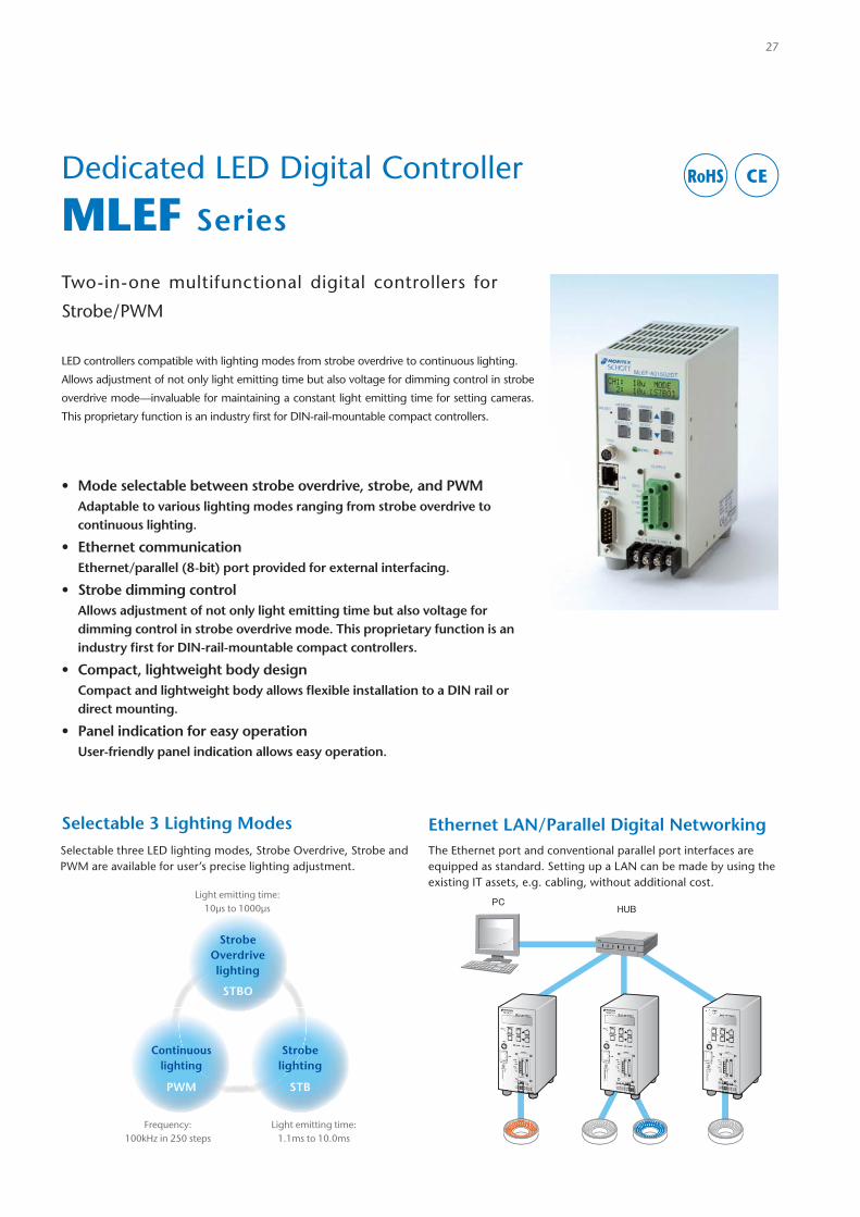
Dedicated LED Digital Controller
MLEF Series
Two-in-one multifunctional digital controllers for
Strobe/PWM
LED controllers compatible with lighting modes from strobe overdrive to continuous lighting.
Allows adjustment of not only light emitting time but also voltage for dimming control in strobe
overdrive mode—invaluable for maintaining a constant light emitting time for setting cameras.
This proprietary function is an industry fi rst for DIN-rail-mountable compact controllers.
• Mode selectable between strobe overdrive, strobe, and PWMAdaptable to various lighting modes ranging from strobe overdrive to continuous lighting.
• Ethernet communicationEthernet/parallel (8-bit) port provided for external interfacing.
• Strobe dimming controlAllows adjustment of not only light emitting time but also voltage for dimming control in strobe overdrive mode. This proprietary function is an industry fi rst for DIN-rail-mountable compact controllers.
• Compact, lightweight body designCompact and lightweight body allows fl exible installation to a DIN rail or direct mounting.
• Panel indication for easy operationUser-friendly panel indication allows easy operation.
Selectable three LED lighting modes, Strobe Overdrive, Strobe and PWM are available for user’s precise lighting adjustment.
The Ethernet port and conventional parallel port interfaces are equipped as standard. Setting up a LAN can be made by using the existing IT assets, e.g. cabling, without additional cost.
Strobelighting
STB
Continuouslighting
PWM
Strobe Overdrive lighting
STBO
Light emitting time:1.1ms to 10.0ms
Light emitting time:10µs to 1000µs
Frequency:100kHz in 250 steps
Ethernet LAN/Parallel Digital NetworkingSelectable 3 Lighting Modes
27
RoHS CE
Adjustment Range
* Total 8-bit and 190 steps
10ms1ms10μs
Strobe Overdrive lightingSTBO
Strobe lightingSTB
Pulse-width ModulationPWM
Strobe mode PWM mode
Inte
nsity
Time
Strobe Overdrive lighting STBO
Trigger synchronization with signal shall be set for the Strobe Overdrive lighting. Light emitting time (i.e. duration) range is 10µs to 1000µs in 100 steps with 10µs increments, also the variable output voltage ranges from 10V-40V.
Trigger synchronization with signal shall be set for the Strobe lighting. Light emitting time range is 1.1ms to 10.0ms in 90 steps with 100µs (0.1ms) increments.
Strobe lighting STB
250 control steps at 100kHZ. Continuous DC lighting with the control value range from (light off) 0 to 250 (maximum).
Continuous lighting PWM
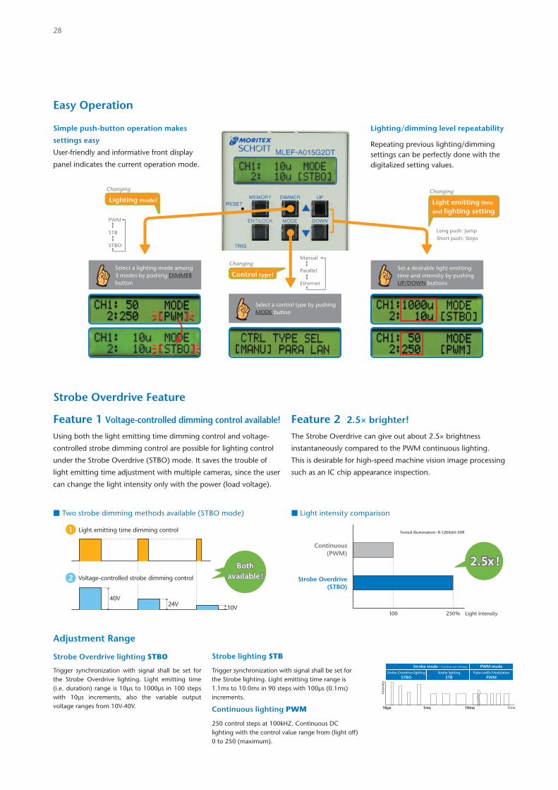
Simple push-button operation makes
settings easy
User-friendly and informative front display
panel indicates the current operation mode.
Lighting/dimming level repeatability
Repeating previous lighting/dimming settings can be perfectly done with the digitalized setting values.
Select a lighting mode among 3 modes by pushing DIMMER button
Select a control type by pushing MODE button
Set a desirable light emitting time and intensity by pushing UP/DOWN buttons
Long push: JumpShort push: Steps
Manual Parallel Ethernet
PWM STB STBO
Changing
Lighting mode!
Changing
Control type!
Changing
Light emitting time
and lighting setting
Easy Operation
Strobe Overdrive Feature
■ Two strobe dimming methods available (STBO mode) ■ Light intensity comparison
Bothavailable !
Bothavailable !
40V24V 10V
1 Light emitting time dimming control
2 Voltage-controlled strobe dimming control
Light intensity100 250%
Tested illumination: R-120X60-50R
Continuous(PWM)
Strobe Overdrive(STBO)
2.5x !2.5x !
Feature 1 Voltage-controlled dimming control available! Feature 2 2.5× brighter!
Using both the light emitting time dimming control and voltage-
controlled strobe dimming control are possible for lighting control
under the Strobe Overdrive (STBO) mode. It saves the trouble of
light emitting time adjustment with multiple cameras, since the user
can change the light intensity only with the power (load voltage).
The Strobe Overdrive can give out about 2.5× brightness
instantaneously compared to the PWM continuous lighting.
This is desirable for high-speed machine vision image processing
such as an IC chip appearance inspection.
28
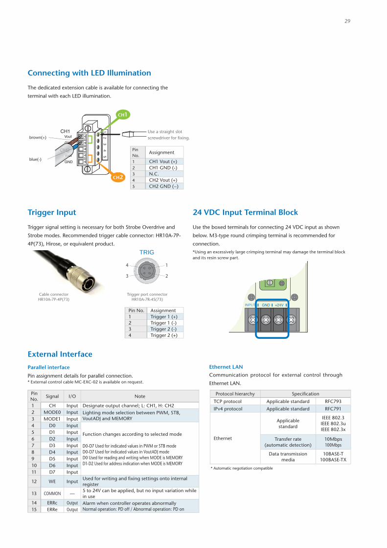
The dedicated extension cable is available for connecting the
terminal with each LED illumination.
Use the boxed terminals for connecting 24 VDC input as shown
below. M3-type round crimping terminal is recommended for
connection.
*Using an excessively large crimping terminal may damage the terminal block and its resin screw part.
Parallel interface
Pin assignment details for parallel connection.* External control cable MC-EXC-02 is available on request.
Trigger signal setting is necessary for both Strobe Overdrive and
Strobe modes. Recommended trigger cable connector: HR10A-7P-
4P(73), Hirose, or equivalent product.
TRIG
1
2
4
3
Trigger port connectorHR10A-7R-4S(73)
Cable connectorHR10A-7P-4P(73)
Ethernet LAN
Communication protocol for external control through
Ethernet LAN.
INPUT +24VGNDINPUT
Connecting with LED Illumination
Trigger Input 24 VDC Input Terminal Block
External Interface
Pin No. Assignment1 Trigger 1 (+)2 Trigger 1 (-)3 Trigger 2 (-)4 Trigger 2 (+)
Pin No.
Assignment
1 CH1 Vout (+)2 CH1 GND (-)3 N.C.4 CH2 Vout (+)5 CH2 GND (−)
53
41
2VoutCH1
GND
Vout
GND
CH2
GGGGNGNG
VoutVouVouVoutoututCH2CCH2CH2
NDbrown(+)
blue(-)
Use a straight slot screwdriver for fi xing.
CH2
CH1
* Automatic negotiation compatible
Protocol hierarchy Specifi cation
TCP protocol Applicable standard RFC793
IPv4 protocol Applicable standard RFC791
Ethernet
Applicablestandard
IEEE 802.3IEEE 802.3uIEEE 802.3x
Transfer rate (automatic detection)
10Mbps100Mbps
Data transmission media
10BASE-T100BASE-TX
Pin No.
Signal I/O Note
1 CH Input Designate output channel; L: CH1, H: CH22 MODE0 Input Lighting mode selection between PWM, STB,
VoutADJ and MEMORY3 MODE1 Input4 D0 Input
Function changes according to selected mode
D0-D7 Used for indicated values in PWM or STB modeD0-D7 Used for indicated values in VoutADJ modeD0 Used for reading and writing when MODE is MEMORYD1-D2 Used for address indication when MODE is MEMORY
5 D1 Input6 D2 Input7 D3 Input8 D4 Input9 D5 Input10 D6 Input11 D7 Input
12 WE InputUsed for writing and fi xing settings onto internal register
13 COMMON —5 to 24V can be applied, but no input variation whilein use
14 ERRc Output Alarm when controller operates abnormallyNormal operation: PD off / Abnormal operation: PD on15 ERRe Output
29
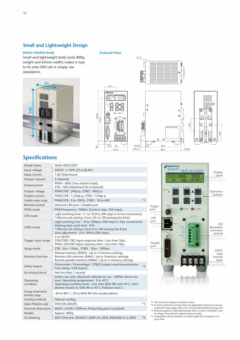
Parallel port
24VDC input
terminal block
LEDillumination connection
terminal
Displaypanel
Operation buttons
Trigger port
LANport
91
8 15
0C 1:2HCH 01 : 1 00
T/sμ S BB/μ s TS
PARALLEL
TRIG
Vout
+24V
GND
INPUT GND
5
ALARM
OUTPUT
VoutCH1
CH2
GND
LAN
REMO
34
21
RESET
MLEF-A015G2DT
ENT/LOCK
MEMORY
MODE
DIMMER
DOWN
UP
MLEF-A015G2DT
139.
8(9
)
119.
7
98.5 (9.8)64.6
9.3
32.3
(45)
(35)
(10.9) 10
(14.2)
(5.3)
78.546
External View
*1 The minimum voltage is a reference value.*2 To reset a protection function (but not applicable to blowout of a fuse),
restore the main supply with a 2 to 3 second interval after turning it off.*3 Protected against a solid object greater than 12.5mm in diameter, such
as a finger. No protection against ingress of water.*4 Compatible with an extension or branch cables (for CompaVis™) of
up to 10m.
Small and Lightweight Design65mm slimline bodySmall and lightweight body (only 800g weight and 65mm width) makes it easy to fix onto DIN rail or simply use standalone.
140
65
Model name MLEF-A015G2DT
Input voltage 24VDC +/-10% (21.6-26.4V)
Input current 1.8A (Maximum)
Output channel 2 channels
Output powerPWM : 30W (Two channel total),STB : 15W (Maximum for a channel)
Output voltage PWM/STB : 24Vp-p, STBO : 40Vp-p
Output current PWM/STB : 1.25Ap-p, STBO : 4.0Ap-p
Variable output range PWM/STB : 0 to 100%, STBO : 10 to 40V *1
Remote control Ethernet LAN port / Parallel port
PWM mode PWM frequency: 100kHz (Control step: 250 steps)
STB modeLight emitting time: 1.1 to 10.0ms (90 steps in 0.1ms increments)* Effective bit setting: From 101 to 190 among the 8 bits
STBO mode
Light emitting time : 10 to 1000µs (100 steps in 10µs increments)Flashing duty cycle limit: 10%* Effective bit setting: From 0 to 100 among the 8 bitsVout adjustment : 0 to 100% (256 steps)
Trigger input range5 to 24VDCSTB/STBO_TRG Input response time : Less than 10µsPWM_ON/OFF Input response time : Less than 10µs
Setup mode STB : 5ms / 10ms, STBO : 10µs / 1000µs
Memory functionManual memory (ROM) : Up to 3 memory settingsRemote LAN memory (RAM) : Up to 3memory settings Remote parallel memory (RAM) : Up to 4 memory settings
Safety featureOvercurrent / Overvoltage / STB(O) output overtime protectionFuse rating: 4.0A (input)
*2
Set reclosing interval Not less than 1 second
Operating condition
Indoor use only, Maximum altitude for use : 2000m above sea level, Operating temperature : 0 to 45°COperating humidity limits : Less than 80% RH until 30°C, then decline linearly to 50% RH at 40°C.Pollution level 2
Storage temperature/humidity range
-20 to 80°C / 20 to 85% RH (No condensation)
Cooling method Natural cooling
Ingress Protection code IP20 (EN 60529) *3
External dimensions W655 x H140 x D99mm (Projecting parts excluded)
Weight Approx. 800g
CE-Marking EMC Directive: EN55011:2009+A1:2010, EN61000-6-2:2005 *4
Specifi cations
30
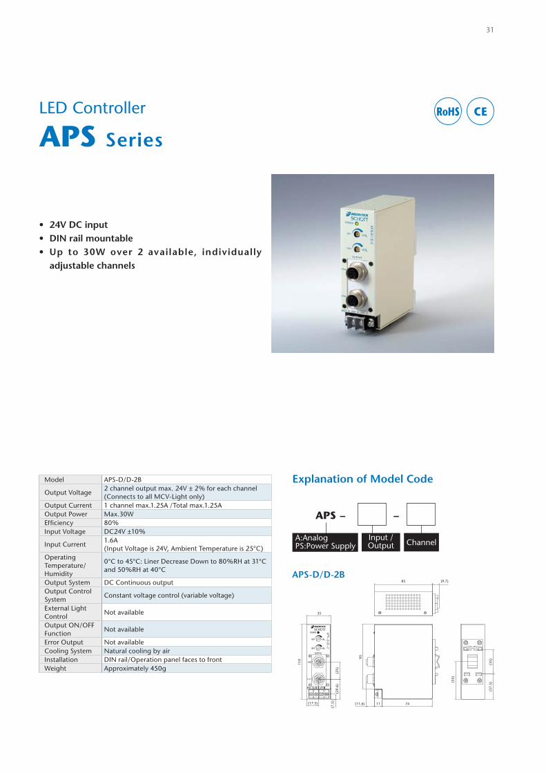
LED Controller
APS Series
Model APS-D/D-2B
Output Voltage2 channel output max. 24V ± 2% for each channel(Connects to all MCV-Light only)
Output Current 1 channel max.1.25A /Total max.1.25AOutput Power Max.30WEffi ciency 80%Input Voltage DC24V ±10%
Input Current1.6A(Input Voltage is 24V, Ambient Temperature is 25°C)
Operating Temperature/Humidity
0°C to 45°C: Liner Decrease Down to 80%RH at 31°C and 50%RH at 40°C
Output System DC Continuous outputOutput Control System
Constant voltage control (variable voltage)
External Light Control
Not available
Output ON/OFF Function
Not available
Error Output Not availableCooling System Natural cooling by airInstallation DIN rail/Operation panel faces to frontWeight Approximately 450g
31
APS-D/D-2B
(11.6) 74
85 (9.7)
11(17.5)
35
(7.5
)(2
9.6)
(25)
95
(55)
(35)
(37.
5)
110
APS - -
A:AnalogPS:Power Supply
Input /Output Channel
RoHS CE
• 24V DC input• DIN rail mountable• Up to 30W over 2 available, individually
adjustable channels
Explanation of Model Code
Cable
32
1000mm
1000mm
Extension Cable
Branch Cable - 2 Way
Branch Cable - 4 Way
Exchange Cable for APS-D/D-2B
Exchange Cable for MLEF-A015G2DT
Model Item Description
JST-1M-JST-1W Extension Cable, SM (3P) to SM (3P), 1000mmJST-2M-JST-1W Extension Cable, SM (3P) to SM (3P), 2000mmJST-3M-JST-1W Extension Cable, SM (3P) to SM (3P), 3000mmJST-5M-JST-1W Extension Cable, SM (3P) to SM (3P), 5000mm
Model Item Description
JST-0.1M-1W Exchange Cable, SM (3P) to Free, 100mmJST-1M-1W Exchange Cable, SM (3P) to Free, 1000mmJST-2M-1W Exchange Cable, SM (3P) to Free, 2000mmJST-3M-1W Exchange Cable, SM (3P) to Free, 3000mmJST-5M-1W Exchange Cable, SM (3P) to Free, 5000mmM12-0.1M-1W Exchange Cable, M12 to Free, 100mmM12-1M-1W Exchange Cable, M12 to Free, 1000mmM12-2M-1W Exchange Cable, M12 to Free, 2000mmM12-3M-1W Exchange Cable, M12 to Free, 3000mmM12-5M-1W Exchange Cable, M12 to Free, 5000mm
Model Item Description
JST-2M-JST-2W Branch Cable, SM (3P) to SM (3P), 2000mm, 2 wayJST-3M-JST-2W Branch Cable, SM (3P) to SM (3P), 3000mm, 2 wayJST-5M-JST-2W Branch Cable, SM (3P) to SM (3P), 5000mm, 2 way
Model Item Description
JST-2M-JST-4W Branch Cable, SM (3P) to SM (3P), 2000mm, 4 wayJST-3M-JST-4W Branch Cable, SM (3P) to SM (3P), 3000mm, 4 wayJST-5M-JST-4W Branch Cable, SM (3P) to SM (3P), 5000mm, 4 way
Model Item Description
JST-0.1M-M12-1W Exchange Cable, SM (3P) to M12, 100mm
JST SMR-03V-B Connector
Ref. Drawing No. Assign Wire Color
1 +V Red / Brown2 NC3 -V Black / Blue
M12 Male Connector
Ref. Drawing No. Assign Wire Color
1 +V Red / Brown2 NC3 -V Black / Blue4 NC
123
1
2
3
4
Illumination Connector
Pin Assign
LED Illumination Data
33
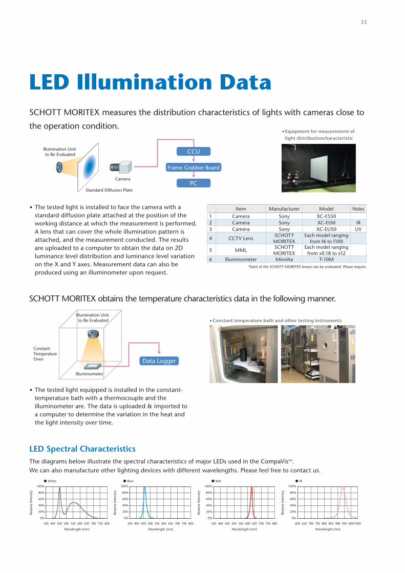
SCHOTT MORITEX measures the distribution characteristics of lights with cameras close to
the operation condition.
SCHOTT MORITEX obtains the temperature characteristics data in the following manner.
LED Spectral CharacteristicsThe diagrams below illustrate the spectral characteristics of major LEDs used in the CompaVis™. We can also manufacture other lighting devices with different wavelengths. Please feel free to contact us.
• The tested light is installed to face the camera with a standard diffusion plate attached at the position of the working distance at which the measurement is performed. A lens that can cover the whole illumination pattern is attached, and the measurement conducted. The results are uploaded to a computer to obtain the data on 2D luminance level distribution and luminance level variation on the X and Y axes. Measurement data can also be produced using an illuminometer upon request.
• The tested light equipped is installed in the constant-temperature bath with a thermocouple and the illuminometer are. The data is uploaded & imported to a computer to determine the variation in the heat and the light intensity over time.
• Equipment for measurement of light distributioncharacteristic
• Constant temperature bath and other testing instruments
Item Manufacturer Model Notes
1 Camera Sony XC-ES50 2 Camera Sony XC-EI50 IR3 Camera Sony XC-EU50 UV
4 CCTV LensSCHOTT MORITEX
Each model ranging from f6 to f100
5 MMLSCHOTT MORITEX
Each model ranging from x0.18 to x12
6 Illuminometer Minolta T-10M*Each of the SCHOTT MORITEX lenses can be evaluated. Please inquire.
CCU
Frame Grabber Board
PCCamera
Standard Diffusion Plate
Illumination Unit to Be Evaluated
Illuminometer
Constant Temperature Oven
Illumination Unit to Be Evaluated
Data Logger
White Blue Red IR
0%
20%
40%
60%
80%
100%
0%
20%
40%
60%
80%
100%
0%
20%
40%
60%
80%
100%
0%
20%
40%
60%
80%
100%
350 400 450 500 550 600 650 700 750 800
Rela
tive
Inte
nsity
Wavelength (nm)
350 400 450 500 550 600 650 700 750 800
Rela
tive
Inte
nsity
Wavelength (nm)
350 400 450 500 550 600 650 700 750 800
Rela
tive
Inte
nsity
Wavelength (nm)
600 650 700 750 800 850 900 950 10001050
Rela
tive
Inte
nsity
Wavelength (nm)
34
Catalog Icon Key
The CE marking (CE mark) is a mandatory conformity mark on many products placed on the singlemarket in the European Economic Area (EEA). The CE marking certifies that a product has metEU consumer safety, health or environmental requirements.
To comply with fire/safety codes, products sold in the United States should be certified to complywith the requirements set by OSHA. A well-known company providing this service in the UnitedStates is UL (Underwriters Laboratories®). The UL Mark on a product means that UL has testedand evaluated programs, product and manufacturing facility and they meet UL requirements. TheUL Marks may be only used on or in connection with products certified by UL. In addition to thesemarks, UL also provides access to the marks required in a number of other world markets. Thereare many types of UL Marks, each with its own specific meaning.
CSA is a Canadian counterpart of UL, given permission by OSHA to test and certify to OSHA safetystandards.
Restriction of Hazardous Substances Directive (RoHS). The Directive on the restriction of the use ofcertain hazardous substances in electrical and electronic equipment 2002/95/EC was adopted inFebruary 2003 by the European Union. The RoHS directive took effect on 1 July 2006, and isrequired to be enforced and become law in each member state. This directive restricts the use ofsix hazardous materials in the manufacture of various types of electronic and electrical equipment.
IP (Ingress Protection) is a set of standard measurements related to the protection of products fromsolid foreign objects and water. IP is prescribed by the Japanese Industrial Standards Committee(JISC0920) and the International Organization for Standardization (IEC60529).IP67 is a level of protection that can withstand being submerged in water at a depth of 1 meter for30 minutes.
RoHS
CE
CSA
UL
IP67
Dimensions and specifi cations in this catalog may vary. Before purchasing,please check the delivery specifi cations or diagrams.
* Company and product names stated in this catalog are trademarks or registered trademarks of their respective companies.* Product specifi cations, design, values, etc. may vary.* The contents in this catalog are for the present as of February 2014.* MG-Wave® is a registered trademark of SCHOTT MORITEX Corporation.* MML is a registered trademark of SCHOTT MORITEX Corporation.* CompaVis™ is currently applied for registration.