Embed Size (px)
Citation preview

24th EXPLOSIVE SAFETY BOARD SEMINAR
HAZARD CLASSIFICATION OF LIQUID PROPELLANTS
BY
WILLIAM 0. SEALS
PICATINNY ARSENAL, DOVER, NEW JERSEY ARMY RESEARCH DEVELOPMENT AND ENGINEERING COMMAND
WILLIAM HERRERA SOUTHWEST RESEARCH INSTITUTE
SAN ANTONIO, TEXAS
CHESTER GRELECKI HAZARD RESEARCH CORPORATION
ROCKAWAY, NEW JERSEY
INTRODUCTION
The lack of a formal protocol in the DoD safety community to evaluate liquid propellants prompted the establishment of a Hazard Classification of liquid propellants program. The DoD safety manual TB-700-2 has been used exclusively for the hazard classification of solid propellants and explosives in storage and transportation. A recent revision of this manual now addresses energetic liquids on a case by case basis. An examination of the UN document and NATO AOP-7 revealed deficiencies in making a final assesment for a dazard Classification of energetic liquids. The Un document only addressed explosives in transportation; while the NATO AOP-7 provides no criteria for making a final judgement to a Hazard Classification. The tests, procedures, and criteria for making a final classification can be found in the TB-700-2. For this reason, the TB 700-2 was selected as the role model for developing the Hazard Classification of energetic liquids.
Since the tests and test procedures found in the TB-700-2 were designed to evaluate solid materials, it became apparent that modifications to these tests and test procedures would have to be made. The liquid propellants LP 1845 and LP 1846 are extremely sensitive to transition metals and nitric acid. Thus, containment of these liquids for a test evaluation would have to be made in a container compatible with these liquid.
This paper will address the events leading up to the selection of the TB 700-2 as the role model for the Hazard Classification of liquid propellants, establishment of the interim- classification tests, test procedures, modifications to the test procedures, and criteria f o r classifying liquid propellants. The recommended tests designed for a final classification will be contingent upon evaluating the liquid propellants in approved DoD packaging.
D
D 1061
Report Documentation Page Form ApprovedOMB No. 0704-0188
Public reporting burden for the collection of information is estimated to average 1 hour per response, including the time for reviewing instructions, searching existing data sources, gathering andmaintaining the data needed, and completing and reviewing the collection of information. Send comments regarding this burden estimate or any other aspect of this collection of information,including suggestions for reducing this burden, to Washington Headquarters Services, Directorate for Information Operations and Reports, 1215 Jefferson Davis Highway, Suite 1204, ArlingtonVA 22202-4302. Respondents should be aware that notwithstanding any other provision of law, no person shall be subject to a penalty for failing to comply with a collection of information if itdoes not display a currently valid OMB control number.
1. REPORT DATE AUG 1990 2. REPORT TYPE
3. DATES COVERED 00-00-1990 to 00-00-1990
4. TITLE AND SUBTITLE Hazard Classification of Liquid Propellants 1061
5a. CONTRACT NUMBER
5b. GRANT NUMBER
5c. PROGRAM ELEMENT NUMBER
6. AUTHOR(S) 5d. PROJECT NUMBER
5e. TASK NUMBER
5f. WORK UNIT NUMBER
7. PERFORMING ORGANIZATION NAME(S) AND ADDRESS(ES) Southwest Research Institute,6220 Culebra Road,San Antonio,TX,78228
8. PERFORMING ORGANIZATIONREPORT NUMBER
9. SPONSORING/MONITORING AGENCY NAME(S) AND ADDRESS(ES) 10. SPONSOR/MONITOR’S ACRONYM(S)
11. SPONSOR/MONITOR’S REPORT NUMBER(S)
12. DISTRIBUTION/AVAILABILITY STATEMENT Approved for public release; distribution unlimited
13. SUPPLEMENTARY NOTES See also ADA235005, Volume 1. Minutes of the Explosives Safety Seminar (24th) Held in St. Louis, MO on28-30 August 1990.
14. ABSTRACT
15. SUBJECT TERMS
16. SECURITY CLASSIFICATION OF: 17. LIMITATION OF ABSTRACT Same as
Report (SAR)
18. NUMBEROF PAGES
51
19a. NAME OFRESPONSIBLE PERSON
a. REPORT unclassified
b. ABSTRACT unclassified
c. THIS PAGE unclassified
Standard Form 298 (Rev. 8-98) Prescribed by ANSI Std Z39-18

DISCUSSION
The UN document was initially examined for potential tests, test procedures, and criteria that might be beneficial in the establishment of a Hazard Classification of the liquid propellants. This initial examination was made based upon the Department of Transportation's acceptance of this document'as their guideline for transporting explosives. As illustrated in Figures 1 and 2, the document determines the division of a Hazard Classification from a series of questions and answers. As seen in Figures 1 and 2, a material is considered for a Class I the answer is yes to the question "is the substance manufactured with the view of producing a practical explosion" Test series 1 is performed if the answer is no. Following this test series, if the answer is yes to the next question "is it an explosive substance?11, then test series 2 is performed. Should the substance be considered as a Class 1 material, then test series 3 is conducted. When the results of test series 3 demonstrate that the material is thermally stable, test series 4 is conducted. The material is provisionally accepted into a Class 1 if packaged substance is considered not too hazardous for transportation.
€or a Division 1.5?'* If the answer is yes, then the test series 5 is performed. Should the results of this test indicate that the substance is an insensitive substance, then it is considered a Division 1.5 material. However, if,the answer to the question above is no, then the packaged substance is subject to test series 6. Depending upon the series of questions asked depicted in Figure 2 and the answers given based upon test results will determine how the material will be characterized. Test series 1 through 6 can be found in Figures 3-8.
The NATO AOP-7 outlines the characteristic qualifications fo r liquid propellants in Fifure 9. Note that in Figure 10, the qualification guidelines follow those of the TB 700-2. Specific physical property tests call for density, melting point, boiling point, ceefficient of thermal expansion, vapor pressure, and f lamabil i ty/detonabil i ty . The required NATO AOP-7 qualification tests are given in Figure 11. Optional qualification tests are cited in Figure lla. Unfortunately, these tests, spelled out for the NATO AOP-7, provide no criteria for assessing or designating a Hazard Classification.
In the TB 700-2, mandatory tests, shown in Figure 12, are required for an interim hazard classification for solid propellants and explosives. Alternate tests that may be required, depending on the application, are depicted in Figure 13. Criteria to establish the interim classification for a Class A or B explosive material are given in Figure 14. No criteria are given for an interim classification for solids as a Class c, explosive. To obtain a final classification, the single Package, stack test, and external fire tests are required. AS
The question now asked is "can the substance be considered
1062

shown in Figure 15, additional tests, such as the bullet impact, fragment, package drop, and oblique drop tests, may be required before a final Hazard Classification can be rendered. The decision to conduct these tests will be determined by the appropriate safety group. The bullet impact and-fragment tests are part of the requirements for an insensitive munition.
The criteria for arriving at a final Hazard Classification for a material are shown in Figure 16. Note that criteria for a Class C material are now given. Include in this criteria should have been that the material does not detonate under atmospheric conditions nor are fragments produced. Schemes for a large scale test analyses are cited in Figure 17 and 18. The single package, stack and external fire tests are the only required mandatory tests for a final Hazard Classification of a material,
presented to the safety community for approval. As depicted in Figures 19, 20, and 21, this methodology received the approval of the tri-services and DoD Explosive Safety Board. Note that for liquids, a Class C designation has been recommended. This differs from the TB 700-2 in that only a Class A or B is given as a result of the card gap test. When 70 or more cards are required to attenuate a detonation in the card gap, a Class A explosive is assigned to the material. If the test results are 70 cards or 0, the, the material is a Class B explosive. It is D recommended that the material be considered a Class C material when 0 cards are used in the card gap test,
modifications had to be made to evaluate a liquid. As shown in Figures 22, 23, and 24, the liquid propellants,were housed in compatible polyethylene sample test containers for testing. This precaution had to be taken since the liquid propellants LP 1845 and LP 1846 are decomposed by transition metals. Contact of these materials with compatible stainless steel containment had to be assured in the impact and critical diameter tests.
All the mandatory and auxillary tests were conducted for LP 1845 and LP 1846. The results of these tests are given in Tables 1-10. The test description of each test is presented below.
Before initiating a test program, a methodology was
Utilizing the tests cited in the TB 700-2 manual,
3, TEST DESCRIPTION
THERMAL
Decontaminate a two(2) inch diameter x 2-1/2 inch high x 0.5 mil thick polyethylene bottle filled with deionized water by placing in an oven at 70C for 24 hours. Weigh the dried bottle. Fill the decontaminated bottle with liquid propellant, weigh the bottle and liquid propellant and place in a constant temperature, explosion proof oven. Raise the temperature to 75C and maintain this temperature for a period of 48 hours. Remove and,weigh the D bottle and liquid propellant. Record the weight change and any reactions that may have occurred over this period of exposure.
1063
CARD GAP
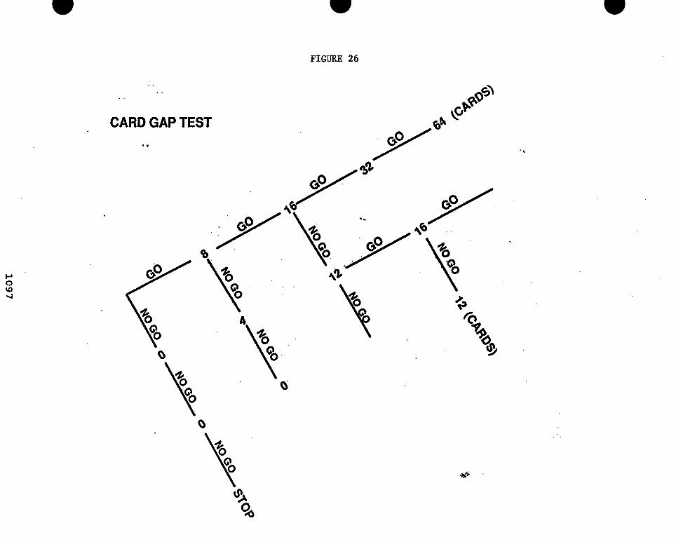
A typical card gap tester is shown in Figure 25, The test apparatus consists of a one piece 1.875 inch 0.D: x 5 . 5 inch long mild steel tube. The ignition source consists of two pentolite pellets that weigh approximately 60 grams and a J-2 blasting cap. A 6 inch x 6 inch x 0.375 inch mild steel witpess plate is used to determine if a detonation has occured. A detonation is indicated when a clean hole is cut into the witness plate. Cellulose acetate(or equivalent) cards 2 inches x 0 . 0 1 inches thick are used to attenuate a detonation. The greater the number of cards, the more sensitive the material. Four small pieces of plastic material cut into (0.0625 x 0.5 x 0 . 5 inches) pieces are used as shims to support the tube and maintain a 0,0625 inch air gap between the test sample and the witness plate.
A 0.5 mil thick polyethylene sleeve is placed inside the mild steel tube to prevent contamination of the liquid propellant, The liquid propellant is placed inside the tube and the first test is conducted, In the first test, the cellulose cards are omitted. Should no detonation occur in the first test, the test is repeated two more times. If a detonation occurs, then a test series given in Figure 26 will be followed with the cellulose cards placed between the tube containing the liquid propellent and the pentolite booster.
The first test performed in Figure 26 is with 8 cards. If a detonation occurs, then the number of cards is doubled (add 8 cards) for the next test. If a detonation occurs in this test, the number of cards is doubled again (add 16 cards). Continue doubling the number of cards until no detonation occurs. When no detonation occurs, then the number of cards is reduced by one half the preceding increment. As an example, if the test is run at 32 cards but not at 64, then the next test will be run at 48 cards. If a detonation occurs at this reduced number of cards, the number of cards will be increased by one half the preceding increment of 56 cards. This test procedure is continued to a point where no detonation is obtained. A 50% probability that a detonati6n has occurred is a measure of charge sensitivity at where a 50% probability that a reaction has occurred at a given attenuation gap length.
IMPACT
The standard JANNAF drop weight tester was used to establish the impact sensitivity of liquid propellants. A typical test sample holder for the apparatus is illustrated in Figure 27. The liquid propellant test sample is enclosed in a cavity formed by a steel cup, elastomeric "Ogl ring and a steel diaphragm, A 4.4 pound (2 kilogram) weight is dropped onto a piston from a height of 48 inches. If a positive result occurs, the weight is dropped from a height one half the original height.This adjustment of the
1064

drop weight to one half the distance is continued until no positive reaction occurs. A positive result has occurred when the steel diaphram is punctured with an accompanied loud report, . severe deformation of the diaphragm or evidence that the sample is consumed. Data are reported at the height which yields 50% probability of initiation.
DETONATION
A lead cylinder, 1-1/2 inch diameter x 4 inches high, is placed upon a 12 inch square x 1/2 inch thick SAE 1010 mild steel plate. Fill a decontaminated polyethylene bottle (2.5 inches high x 2 inches in diameter) with a liquid propellant sample. A no, 8 blasting cap with the following requirements is placed perpendicular and in contact with the liquid surface:
1. A cap containing 0.4-0-45 grams of PETN base charge pressed into an aluminum shell having a bottom thickness not to exceed 0.03 inches.
2. A specific gravity not less than 1.4 grams/cubic centimeter.
3. Primed with standard weight of primer in accordance with the manufacturer's specifications.
In the center of a wooden block, drill a hole and position the blasting cap. Ignite the blasting cap and examine the lead cylinder for and deformation. Any deformation of the lead block that is 1/8 inch or more will be considered evidence that a detonation has occurred. Conduct a minimun of five tests more or until a detonation has occurred.
D
IGNITION AND UNCONFINED BURNING
Kerosene soaked sawdust is placed in a 12 inch x 12 inch x 4 inch stainless steel container with a 1/16 inch wall thickness. The sawdust is evenly filled to a level of 1/4 inch. A 2 inch diameter decontaminated polyethylene bottle is filled with a 2-1/2 inch height of liquid propellant. The polyethylene filled with test'sample is placed in the center of the kerosene soaked sawdust and ignited with an electric match-head igniter. This test is repeated twice.
Four liquid propellant filled decontaminated polyethylene bottles are placed in the center of a container filled with kerosene soaked sawdust. The bottles are placed in a row with each bottle in contact with the next bottle. The sawdust is ignited at one end with an electric match-head igniter. The test is repeated two more times.
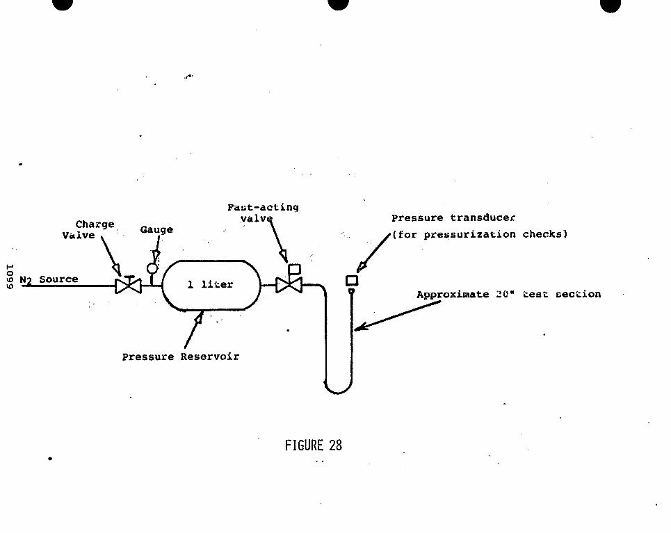
ADIABATIC COMPRESSION
The schematic of the U-tube compression ignition test set-up is illustrated in Figure 28. The following test parameters are
B 1065

required:
U-tube radius Sample volume U-tube height Ullage space Tubing material Tubing diameter Pressure valve orifice
1.0 inch 3.0 cubic centimeters 9 . 0 inches *
6.0 inches 304 stainless steel 0.25 inch O.D. x 0.035 thick 0.187 inches
The U-tube is closed at one end with a cap. A 3 ml. quanity of test fluid is placed in the curvature of the U-tube. The open end of €he U-tube is connected to the discharge valve. A reservoir is pre-pressurized with nitrogen to 2000 psi. The test is conducted by a suddenly pressurizing the U-tube. The pressure surge Torces tEe liquid in the curvature to violently compress the ullage space containing the liquid vapors into the closed end. This rapid rate of pressurization is sufficient to provide adiabatic compression. Rupture of the U-tube is an indication that an explosion or detonation has occurred. The test is repeated with nitromethane as a control and the test results are compared,
CRITICAL DIAMETER
A schematic of the critical diameter test setup is shown in Figure 29. Tests are conducted using different size diameter cylinders with L/D ratios of 2:l. The liquid propellant tests were conducted using 2 ,384 and 5 inch diameter aylinders. Each cylinder was welded to a 316 stainless steel 1/4 inch thick witness plate,This assembly was passivated with nitric acid to remove any potential contamination. An explosive C-4 charge is placed on top of the open end of the container filled with the liquid. A 0.5 ml thick polyethylene sheet separates the charge and liquid. As the size of the container increases from 2 to 4 inches, the explosive charge was increased proportionally to ensure that the same energy per unit area was maintained, The 2 inch te.sts were conducted with 160 grams of C-4, the 3 inch tests use'd 360 grams, the 4 inch tests used 640 and the five inch tests required 1000 grams for each test. These C-4 charge weights were chosen to produce a fixed energy input of 3.11 x 10⁵ Joules/sq in. Detonation velocity probes were inserted into the cylinders to determine the shock wave velocity as it travels through the liquid. The explosive charge is- ignited and any reaction is recorded on motion picture film.
FLASH POINT
The standard procedure for the ASTM-92-72 Cleveland Open Cup Flash Paint Test Method was followed to evaluate the liquid propellants. The standard brass cup used in this procedure was replaced by a Pyrex cup that reduced the standard volume from
1066

70 ml. to approximately 50 ml. The cup was filled with liquid propellant and placed in the test apparatus.. The fluid filled cup was heated to 25C. A gas-fired flame was passed over the - liquid. If no flash occurred, the temperature was,raised in increments of 1OC to a maximum of 75C. The lowest temperature where the pilot flame caused the vapors above the liquid to ignite was taken as the flash point.
. . MINIMUM PRESSURE FOR VAPOR PHASE IGNITION
A schematic for the pressure test vessel for vapor phase ignition is depicted in Figure 30. Water is used to calibrate the vessel. The vessel is evacuated and 2 ml. of distilled water is injected into the vessel. The temperature is slowly raised at a rate of 5C per minute. At the 5C intervals, pressure and temperature are recorded. A sample of n-propyl nitrate is used as a standard for comparison, A fuse wire, 3 inches in length, is installed in the vessel such that 1 inch is unsupported. The vessel is evacuated and 2 ml. of n-propyl nitrate is injected into the vessel. The temperature of the liquid is raised to a temperature of 16dC (use caution). Reduce the pressure to 2.2 atmospheres (29 psia). Ignite the vapor with the fuse wire and record the voltage, current, and pressure. Repeat the test two more times.
sample of liquid propellant is injected into the vessel, The temperature is slowly raised at 5C per minute until 1OOC is reached and then an attempt at ignition is made. Record voltage, pressure and current at this temperature. If no 'ignition occurs, discontinue the test restart test with procedure cited above except raise the upper limit of the temperature 5 C and attempt ignition. If no ignition occurs, repeat the test until.ignition or a reaction occurs. At each of these ignition points, record the voltage, current and pressure.
The apparatus is cleaned with distilled water and 3 ml test B
EUCTROSTATICS
Electcostatic energy stored in a charge capacitor is discharged to the sample material to determine whether the electrostatic discharge will cause a sample to decompose, flash, burn, etc. The liquid sample is placed in a stainless steel 316 sample holder or equivalent material compatible with the liquid propellant that will permit the discharge to pass through the sample. The capacitor has a 50000 volt potential. A discharge needle is lowered above the liquid until a spark is drawn through the liquid sample (20 mg.). The standard test interval ranges from 0.0001 microfarads (uf) and 0.00125 Joules at 5 kV to 1 uf and 12.5J at 5 kV. The test is initiated at 1 uf and 12.5 J level. If a negative result occurs, testing is at this level until 20 negatives are reported. If the result is positive, such as a spark, flash, burn, odor or noise other than the instrument noise, a lower discharge level is selected until
' 1067

20 or more energetic results occur. The test voltage of 5 kV or less at ambient temperatures between 18.3C and 32.2C is used with a relative humidity not to exceed 40%.
DISCUSSION OF RESULTS THERMAL
The thermal test (Table 1) is the test used by the Department of Transportation ills a basis for "forbidden" materials for transportation. Had a detonation occured with the LP materials, the materials could not be shipped. Both materials indicated minimal loss in weight with no visible signs of a reaction having taken place.
CARD GAP
The card gap test results found in Table 2 indicated that zero (0) cards were used. This reflects the insensitivity of the liquid propellants, Lp 1845 and LP 1846. It is felt that the length of the sample holder tube, 5.5 inches, may not provide-enough residence time for the shock wave to cause a reaction. It is suggested that the tube length be increased to 16 inches. Another concern is the diameter of this sample tube. The diameter can be below the critical diameter and, as such, will not support the transmission of detonation wave.
IMPACT
Table 3 lists the inpact test data for LP 1895 and LP 1846. Since LP 1846 has approximately 3% more water than LP 1845, the difference of only 1 inch between the two was to be expected, and LP 1845 more sensitive. Nftromethane, classified by the Department of Transportation as a flammable liquid is more sensitive than the liquid propellants.
DETONATION
Detonation test data are given in Table 4. As seen, no detonations occurred in LP 1845 or LP 1846. The Department of Defense Safety community considers this test as a mandatory critical test. requirement would immediately characterize the material as a Class A Division 1.1.
IGNITION AND UNCONFINED BURNING
A detonation by a material under this test
The test results for ignition and unconfined burning are The transfer of thermal heat from sawdust shown in Table 5.
soaked in kerosene to liquid propellant samples produced to reaction. the storage of propellants. detonation can occur of a fire hazard.
This test simulates a fire that could develop during The question resolved is whether a
1068

ADIABATIC COMPRESSION
Adiabatic compression test results are depicted in Table 6. When a pressurization rate of 260,000 psi/sec was applied to LP 1845 and LP 1846, no detonations or explosions occured. It is critical that the same test configuration be used for each test; otherwise, erroneous test data can be obtained. It has been found that a slight change, such as replacing the end cap with a pressure transducer cap, will have a pronounced effect upon the test results. The standard end cap which has a conical interior produced a detonation when tested with nitromethane. When a flat interior transducer cap replaced the standard cap, no detonation occured. Both tests were conducted at the same pressurization rate. It is theorized that there is a heat transfer problem associated with the conical interior cap. A bubble can be trapped in the conical space which can afford a hot spot for a reaction to occur.
CRITICAL DIAMETER
Critical diameter test data for LP 1845 and LP 1846 can be found in Table 7. The detonation probes indicated that no detonations occurred with LP 1845 in the 3 inch diameter test cylinders; but, a detonation was detected in the 4 inch diameter cylinder. LP 1846 proved to be less sensitive. Here no detonation was detected in the 4 inch diameter cylinder; however, a detonation wave was seen in the 5 inch diameter cylinder. This differential in the critical diameter can be attributed to approximately 3% more water in the'basic LP 1846 stoichiometric formulation. The recommended 3:l charge height to diameter was not followed from the standard test because the deviation in the planar wave across the diameter from the test charge used in this test would be negligible.
FLASH POINT
Table 8 records the flash point test data results for LP 1845 and 4p 1846. LP 1845 and LP 1846 are stoichiometric formulatioh containing 16.8% and 20.0% water, respectively. The vapor above both these compounds is essentially water. Therefore, one would expect that there would be no flash point for both these materials, and this was the case for both materials.
MINIMUM PRESSURE FOR VAPOR PHASE IGNITION
LP 1845 and LP 1846 minimum pressure for vapor phase ignition data can be found in Table 9. As in the case for flash point, the vapor above the liquid phase is water. In this test, the LP materials began to decompose when the temperature reached 120C. Thus, there is no minimum pressure for vapor phase
1069

gnition as the material does not ignite under these conditions.
ELECTROSTATICS
The electrostatic test results for both liqurd propellants evaluated can be seen in Table 10. Both materials proved negative to electrostatic ignition. and triethanolammonium nitrate are nitrated salts that are , completely ionized in the water portion of the basic formulation. Therefore, electrostatic charge build-up is readily dissipated through these formulations and can not materialize into a hazardous discharge.
Hydroxylammonium nitrate
SUMMARY
Based upon the results of the small scale interim classification tests, the safely community assigned a Hazard classification of Class B Explosive, Division 1.3C. The assignment of a compatibility Group C poses a problem for the logistics chain. The safety community has characterized these materials as oxidizers. This assignment is incorrect since the basic formula contains an oxidizer and a fuel component. As a ~ r o u p c catagory, liquid propellants can nat be stored with solid materials. However, they can be stored with other oxidizers. To place this under a Group J category which is designated for liquid propellants and gels would require that the materials be stored separately from any other material. can see the dilemma, A program has been recommended to resolve this problem, ,
propellants sensitivity to decompose in contact with transition metals and nitric acid can be resolved. practices and storage containers compatible with the liquid propellants can eliminate or greatly reduce the threat of contaminating the liquid propellant. that is in progress, will greatly enhance the design of the containers for long term storage. Any pressure generated from the HAN-bpsed propellant's decomposition can be relieved through proper vefiting techniques and avoid any safety hazards while in storage.
liquid porpellants are very insensitive to initiation. Destruction of armored vehicles has been the result of stored ammunition detonating when hit by a shaped charge. insensitive munitions is critical for the preservation of the vehicle and more importantly the personnel. Successful gun firings of the HAN-based propellant in the 155mm regenerative gun scheduled for 1991 will usher in a new era for tactical weapons systems. The Hazard Classification program has paved the way for this attainment. presentation.
One
The problems associated with the HAN-based liquid
Strict manufacturing
The surveillance program,
The results of various tests have shown that the HAN-based
The need fo r
This concludes the paper
1070

UNITED NATIONS HAZARDOUS SUBSTANCE ACCEPTANCE PROCEDURE. 1 14
FIGURE 1 -. ..- __ . 1071

UWTED NATIONS PROCE3URE FOR ASSlGNMUJT OF HAZARb DIVISION
1072

W W
FIGCRE 3
UN DOCUMENT TEST SERIES 1
* TYPE ‘ 1 (a) TESTS: SHOCK TESTS WITH A QEFINED BOOSTER UNDER CONFINEMENT
* TEST 4 (a) (1) BAM 50/60 STEEL TUBE TEST * ?TEST 1 (a) (ii) TNO 50/70 STEEL TUBE TEST * TEST 1 (a) (iii) CARD GAP TEST FOR SOLIDS * TEST 1 (a) (iv) CARD GAP TEST FOR LIQUIDS c.‘
0 4 W * TYPE 1 (b) TESTS: COMBUSTION OR THERMAL TESTS
* TEST 1 (b) (i) KOENEN TEST * TEST 1 (b) (ii) INTERNAL IGNITION * TEST 1 (b) (iii) SCB TEST

FIGURE 4
UN DOCUMENT TEST SERIES 2
- * TYPE 2 (a) TESTS: SHOCK TESTS WITH DEFINED BOOSTER UNDER CONFINEMENT
*
* TEST 2 (a) (i) BAM 50/50 STEEL TUBE TEST * * TEST 2 (a) (ii) TNO 50/70 STEEL TUBE TEST
TEST 2 (a) (iii) GAP TEST FOR SOLIDS * TEST 2 (a) (iv) GAP TEST FOR LIQUIDS
TYPE 2 (b) TESTS: COMBUSTION OR THERMAL
* TEST 2 (b) KOENEN, TEST * TEST 2 (b) (i) INTERNAL IGNITION * TEST 2 (b) (i i) TIME/PRESSURE TEST * TEST 2 (b) (iii) SCB TEST

. . FIGURE 5
T
UN DOCUMENT TEST SERIES 3
TO IMPACT * BUREAU OF. EXPLOSIVE MACHINE * BAM FALLHAMMER
* 30 kg FALLHAMMER * MODIFIED TYPE 12 IMPACT TOOL
(B) SENSITIVITY TO FRICTION * BAM FRICTION APPARATUS * ROTARY FRICTION * ABL FRICTION
(C) THERMAL STABILITY * THERMAL STABILITY TEST AT 75C
(D) RESPONSE TO FLAME * SMALL SCALE BURNlNG.TEST (USA) * SMALL SCALE BURNING TEST (FRENCH)
- * ROTTER TEST

FIGUFE 6
UN DOCUMENT TEST SERIES 4
. * TYPE 4 (a) TEST: THERMAL STABILITY OF PACKAGED
OR UNPACKAGED SUBSTANCES
* TEST 4 (a) THERMAL STABILITY TEST FOR ARTICLES AND PACKAGES
* TYPE 4 (b) TESTS: EFFECT OF DROPPING THE EXPLOSIVE FROM A HEIGHT OF A FEW METERS
* TEST 4 (b)(i) STEEL TUBE DROP TEST FOR LIQUIDS * TEST 4 (b)(ii) TWELVE METER DROP TEST FOR
ARTICLES AND SOLID SUBSTANCES

W W FIGURL 7
UN DOCUMENT . . TEST SERIES 5'
* TEST * . ,5(a): SHOCK TESTS-IGNITION. BY STD. DETONATOR
* TEST 6(a) CAP SENSITIVITY TEST
*' TEST 5(b): THERMAL TESTS
* TEST 5(b)(i) : DDT * TEST S(b)(ii): DDT
TEST= rGNlTlON BY- HOT WIRE TEST= 5 GRAM IGNITER
* TEST 5(C): SUBJECT TO
? EXTERNAL FIRE TEST
*. TEST. 5 ( ~ ) : IGNITION BY
LARGE FIRE
. . . .
INCENDIARY SPARK
, * PRINCESS INCENDIARY SPARK TEST
** NOTE: HAZARD DIVISION 1.5 MUST PASS ALL TESTS

FIGURE 8
UN DOCUMENT TEST SERIES 6
* TEST TYPE 6(a): TEST ON SINGLE PACKAGE .. .' * WHETHER INITIATION OR IGNITION
CAUSES BURNING OR EXPLOSION
- * SURROUNDINGS ENDANGERED BY THESE EFFECTS
* TEST TYPE 6(b): TESTS ON STACK OF PACKAGES
* WHETHER BURNING OR EXPLOSION IS PROPAGATED FROM ONE PACKAGE TO ANOTHER
* TEST TYPE 6 ( ~ ) : EXTENAL FIRE TEST
* HOW PACKAGES IN STACK BEHAVE TO EXTERNAL FIRE
* SURROUNDINGS ENDANGERED BY BLAST WAVES, HEAT RADIATION AND FRAGMENTS

W W W . FIGURE 9
NATO CHARACTERISTIC QUALIFICATION . . ' .FOR LIQUID PROPELLANTS
0
1. GENERAL CHARACTERISTICS 4
1.1 COMPOSITION 1.2 TYPE\ROLE 1.3 RELATED APPLICATIONS & .
1.4 FABRICATIONS P 0 1.5 PHYSICAL PROPERTIES
COMPOSITIONS
4 u)
2. CHEMICAL CHARACTERISTICS *
2.1 STABILITY 2.2 COMPATIBILITY 2.3 TOXICITY
3. PROPELLANT CHARACTERISTICS 3.1 BURNING CHARACTERISTICS 3.2 IMPULSE\IMPETUS 3.3 HEAT OF COMBUSTION

---
FIGURE 10 1
E i/ ! '
I'
: / / . '1 ' i m 0
QUALIFICATION (NATO) -FOR LIQUID PROPELLANTS
* QUALIFICATIONS GUIDLINES * DOD TB 700-2
*TO 13 Ail-47 * NAVSEAINST 8020.8
* DLAR 8220 * QUALIFICATIONS * PHYSICAL PROPERTIES * DENSITY * MELTING POINT * BOILING POINT * COEFFICIENT OF THERMAL EXPANSION * VAPOR PRESSURE. * FLAM M AB I LITWD ETON AB I LlTY
* COMPATIBILITY * TOXICITY
* CHEMICAL PROPERTIES
m . .
. '
L
,
.

W W W - FIGURE 11
NATO QUALIFICATION TESTS FOR HAZARD CLASSIFICATION OF LP
* UNCONFINED BURNING ( BONFIRE )
* IMPACT
* CARD ..GAP
P * MINIMUM PRESSURE FOR VAPOR PHASE IGNITION 0
01 P
* FLASH POINT
* ADIABATIC COMPRESSION
* DETONATION VELOCITY

*
*
*
P * 0 02 N
FIGURE 1 1 ~
NATO - OPTIONAL QUALIFICATION TESTS . FOR LIQUID PROPELLANTS
. . *
ATTACK BY FRAGMENT
HIGH VELOCITY IMPACT
DROP TEST PACKAGE
OBLIQUE IMPACT
*.
I
* CRITICAL CONDITIONS FOR SELF HEATING

w FIGURE 12
*
*
*
*
*
INTERIM HAZARD CLASSIFICATION TESTS FOR LIQUID PROPELLANTS
9 . . THERMAL STABILITY
IMPACT
CARD GAP
DETONATION TEST
IGNITION AND UNCONFINED BURNING
MANDATORY

FIGURE 13
a
. _ . HAZA.RD CLASSIFICATION TESTS .. . ..
. .. * JANNAF THERMAL STABILITY
* ,ADIABATIC COMPRESSION
* CRITICAL DIAMETER
* FLASH POINT -
* MINIMUM PRESSURE FOR VAPOR PHASE IGNITION
* ELECTROSTATICS
.

FIGURE 14
. .
EVALUATION CRITERIA
SMALL SCALE TESTS (INTERIM) ..
DOT 'FORBIDDEN-
- Thermal Stability: detonation, burning, - marked decomposition
DOT CLASS A (DO0 1.1) - if one or more occsus
- Detonation Test: 118 hch or mare defgrmation
- Card Gap Test detonation sensitiv'By of 70 or more cards
- Impact sensitivity:-expiosion at 4 inches, but ~ not more than 10 mcfies
- Ignition and Unconfined Burning. debnation
of lead cylinder
Y;
B -
DOT CLASS B (DO0 1.3) - if A U OW
- Ignition and Unconfmed Burrring deftagration
- Thermal S t a m - no tea18
- Detonation test 1r0 detonation AND Card Gag. detonation sertsifiyify lessthan70
cards OR no teach at zero cards
- M a c t ~msitivity: no ex- at 30 or less
1085

FIGURE 15
P 0
HAZARD CLASSIFICATION LIQUID PROPELLANT END ITEM TESTS
’. * SINGLE PACKAGE TEST
* STACK TEST
* EXTERNAL FIRE
* BULLET IMPACT (50MM)
* PACKAGE DROP TEST
* OBLIQUE PACKAGE DROP TEST
* FRAGMENT TEST ,
FULL SCALE TESTS
0

FIGURE 16 B LIQUID PRUPEllANT CUJ UEMON$TRATION PROGRAM
EVALUATION CRITERIA '
LARGE SCALE PACKAGE TESTS (FINAL)
DOT CLASS A (DOC) 1.1)
- Packages mass detonate
- Euik materials with Card Gzp of 70 or more cards
DOT CLASS A (DO0 1.2)
- Packages do not mass detonate .
- Package tests produce hazardous fragnents ,
DOT CLASS B (DO0 1.3)
- Packages do not mass detcMte
- EuIk materiais with Card Gap of less than 70 cards
- Radiant heat flux 0.3 cz#/sq en-sec beyond 100 feet
DOT CLASS C (DO0 1.4)
- Hazardous fragment and firebrand den53 no more
- Radiant heat flux no more ihan 0.3 W s q m-sec
than one1600 sq ft beyond 1W feet
beyond 100 feet .
1087

FIGURE 17
. -
. . . .
HAZARD NOT HAZARD EXPECTED EXPECTED
I
HAZARD CLASSIFICATION PACKAGE TEST ANALYSES
' SINGLE
PACKAGE TEST
SEVERE , NO SEVERE EFFECTS EFFECTS
NO DETONATION DETONATION j D I Y . 1 . 4 G I
MULTI-PACKAGE TESTS
m L
EXTERNAL FIRE D ETON AT1 ON NO DETONATION TESTS c

FIGURE 18
. . HAZARD CLASSIFICATION . * PACKAGED MATERIAL ANALYSES
I I ' ' 1-1 PACKAGED MATERIAL 1-1
I I I I I HAZARD EXPECTED1
I I
M U LT I - PAC KAG E
NO DETONATION
' (DETONATION I h 1 I I
MAIN EFFECT FIRE OR MASS FIRE
DIV. 1.3
TOTAL. DETONATION OF CONTENTS
DIV. 1.1
I I r 4
LITTLE EFFECT TO EXTERNAL PACKAGE
DIV. 1.4
MAIN EFFECT FRAGMENTS DIV. 1.2
I L 1

FIGURE 19
* I >
, Screening , ExplolrIve 7 . LiWM Ptopwfllan t Tests Reaction
2 Hazard Classifioation Methodology
).
P 0 \D 0
* t
I Hazard Classification I
Reaction c
i J m .c
Critical Critical ass Diameter
- No Explosive Explosive Reaction React ion 9 e

c,
Impact Thermal
. .
Card Cap Compression Electro=
W
FIGURE 20
No = Go Reaction Methodology
a Ignition Static a
r ?
Crltlcal Critical Diameter ! t
Mass
Variable Pipe Bullet Bon- Packaged Dlameter Impact ~ Fire Drop Tests ,
J
i o R ? I

FIGURE 21
No " G o ,
Y
* , Explosive
0
Raaction
Explosive Reaction Methodology
Reaction ,
/Screening Tests]
, Card Cap] [impact 1 C o m p m b n IglRitWl
..
I Class A 1
v
1888 DEA 1080 Woif'hop
m

FIGURE 22
TB 700-2 SOLID V S LIQUID PROPELLANT TEST COMPARISON
Solid Propellant Liquid Propellant
THERMAL' STABILlTY TEST REQUIREMENTS
Constant temperature oven
75'C for 48 hours
2-in- propellant cube
ZARD GAP TEST REQUIREMENTS
rubing 1-7/8 in. diameter, 5.5 in. long
Two pentolite pellets
Engineers blasting cap
Steel plate 6x6~318 in.
Propellant sample machined or cast 7-7/8 in- diameter, 5-5 in, long
Constant temperature oven
75'C for 48 hours
8 cu in- of LGP In a 2-in. diameter polyethylene bottle
Tubing 1-718 in. diameter, 5.5 in. long
Two pentolite pellets
Engineers blasting cap
Steel plate 6x6x3/8 in.
Propellant in a 1,5..mil polyethylene liner 1=7/8 inm diameter, 5,5 in, long

FIGURE 23
TB 700-2 SOLID VS. LIQUID PROPELLANT TEST COMPARISON
Solid Propellant Liquid Propellant
DETONATION TEST REQUIREMENTS
1.5-in. diameter lead cylinder . 1.5-in. diameter lead cylinder
No. 8 blasting cap No, 8 blasting cap encased in 15rniI plyethylene film
2-in. propellant cube 8 cu in. of LGP in a 240. diameter
MIITION AND UNCONFINED BURNING TEST REQUIREMENTS
0 !-J polyethylene bottle \D rfr
Kerosene-soaked sawdust bed Kerosene-soaked sawdust bed
Electric match igniter Electric match igniter
2-in. propellant cube 8 cu in. of LGP in a 2-in, diameter polyethylene bottle

FIGURE 24 TB 700-2 SOLID VS, LIQUID PROPELLANT TEST COMPARISON
Solid Propellant :. .
Liquid Propellant
IMPACT SENSITIVITY TEST REQUIREMEN-fS
Bureau of ExplQsives tester Bureau of Explosivcs tcstcr
Sample placed in cup assembly Sample placed in stainless steel cup assembly modified to acccpl liquids
Ten tests at 3-3/4 in. drop height
Ten tests at 10 in. drop height
Ten tests at 3-3/4 in. drop height
Ten tests at 10 in. drop height
CRITICAL DIAMETER TEST R EQ U I R €ME NTS
Vclocjty probes
Witness plate
Velocity probes .
Stainless sicel witness plait wdded to iubing
Pentolite explosive charge, 51 grams C-4 explosive charge, 31 1 ItJouIeslii-i'!
E-99 detonator E-99 detonator
Tubing, 118 to I in. OD Stainless steel tubing 2, 3, 4, and 5 ~ I -L OD wifh wall thickness of 0.0625 in. Wclded assembly must,, be passivated with niiric acid prior ro test
I

Figure 25: Card Cap Test Configuration
1096
LI 9
0
1097

. .
t
FIGURE 27 - SAMPLE C U P ASSEMBLY
' 1098
Fast-acting valve Pressure transducer
/ ( for pressurization Gauge I Valve \
1 liter P
u) 5: N2 Source
7- Pressure Reservoir
n Approximate ?!ow I/ U
checks)
tesc seckion
FIGURE 28 1 .

FIGURE 29
CRITICAL DUHETER TEST SET-UP
0 0
SARAN W U P SEAL _I
LI
jk, I
I 1 I
I I I I 1 I
, I I
I I
C-4 BOOSTER CHARGE / CONTINOUS VELOCITY PHOBE /
.065 WALE STAINLESS STEEL TU /
STAINLESS STEEL WITNESS PLATE 1 WOODEN SHIM BLOCK t h -
I

TRANSDUCER
TR, NSDUCER
/ 9 / 1 6 '
FUSE W HOLDER
7 . t 2 5 '
L
STUDS
CARTR I HEATER
RE
DGE S
J TC
DRA 1 N
& SWAGELOK J . 8 . VALVE
Figure 3 o Pressure Test Vessel
1101

TABLE 1
THERMAL STABILITY TEST RESULTS 48 HOURS AT 75’C IN VENTED OVEN
SAMPLE ID REACTION
LP 1845 NONE LP 1846 NONE

TAELE 2
CARD GAP DATA FOR LP 1845 AND LP 1846
4-1
SAMPLE NUMBER OF VISUAL CARDS I D E N T I F I CAT I ON 0 BSE RVATI ON
1. LP 1845 0 WITNESS PLATE DEFORMED NO HOLES IN PLATE
2. LP 1846 0 WITNESS PLATE DEFORMED P P NO HOLES IN PLATE 0 W

TABLE 3
IMPACT TEST DATA FOR LP 1845 AND LP 1846
SAMPLE ID
LP 1845 LP 1846
DROP HEIGHT (IN.) 0% 50% 100%
28 30 31 29 30.5 33
0

TABLE 4
.. .
DETONATION TEST RESULTS
SAMPLE ID DETONATION P CI 0 01 LP 1845 NONE
LP 1846 NONE
REACTION.
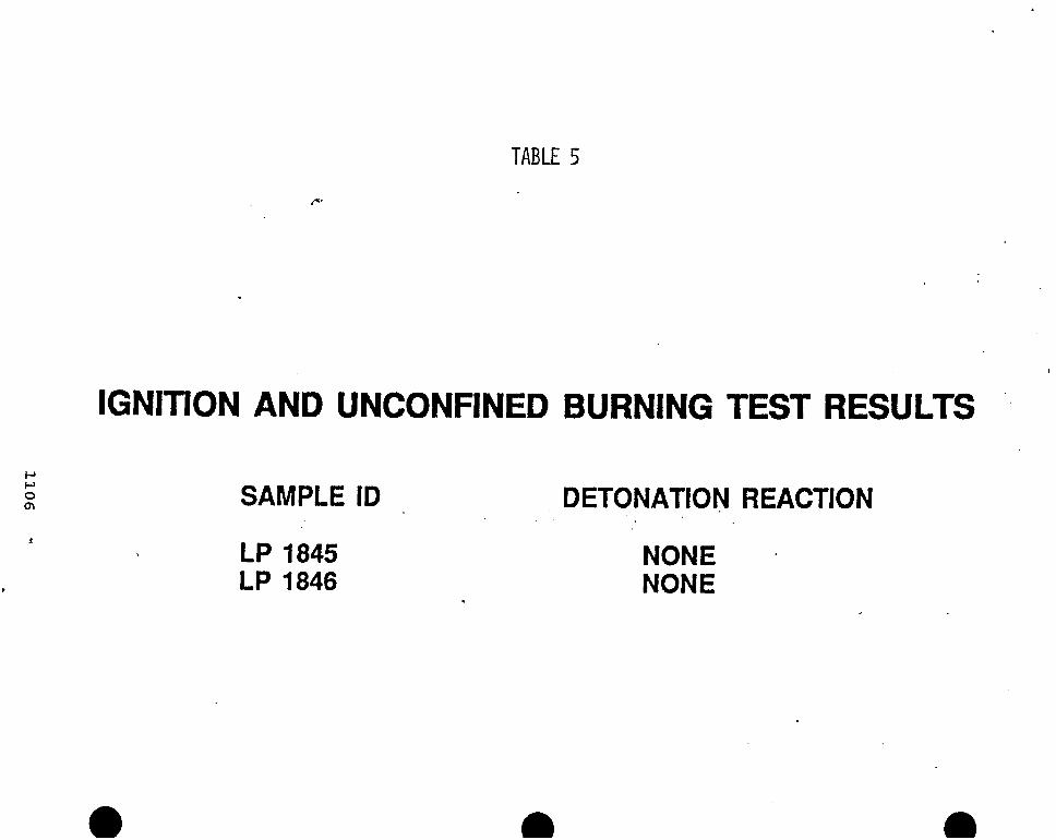
TABLE 5
IGNITION AND UNCONFINED BURNING TEST RESULTS ' .
P P O cn SAMPLE ID DETONATION REACTION
LP 1845 NONE P LP 1846 NONE
d
m
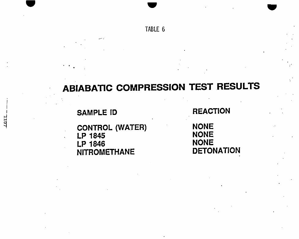
TABLE 6 .- /
. .
I
I i SAMPLE ID REACTION
CONTROL (WATER) LP 1845 LP 1846 NITROMETHANE
NONE NONE NONE DETONATION

TABLE 7
CRITICAL DIAMETER TEST DATA r-3
SAMPLE BAFFLES* DE TON AT I ON I DEN TI F I CAT I ON REACTION
1. LP 1845
2. LP 1846 P P 0 m
3. LP 1845
NO NO REACTION AT 3 INCHES REACTION AT 4 INCHES
NO NO REACTION AT 4 INCHES REACTION AT 5 INCHES
YES NO REACTION AT 3 INCHES REACTION AT 4 INCHES
4. LP 1846 YES NO REACTION AT 4 INCHES REACTION AT 5 INCHES
* WHIFFLE BALL TYPE POLYETHYLENE SPHERES OCCUPYING APPROXIMATELY 12% OF THE CANISTER VOLUME *

TABLE 8
FLASH POINT 75'C (PROPANE FLAME)
SAMPLE ID REACTION
LP 1845 NO REACTION LP 1846 NO REACTION

i
TABLE 9
rlr: _ . . ..
i
.. .
I MINIMUM PRESSURE FOR VAPOR PHASE IGNITION I
I
I fr
I SAMPLE ID REACTION
WATER (CONTROL) NONE LP 1845 NONE (MATERIAL DECOMPOSED) LP 1846 NONE (MATERIAL DECOMPOSED)
1:
m a

W
TABLE 10
ELECTROSTATIC TEST RESULTS 1 MICROFARAD AND 12.5 JOULES AT 5 KV
SAMPLE .ID REACTION
LP 1845 LP 1846
NO REACTION NO REACTION


![OPERATION MANUAL - for-a.com€¦ · nature. Hazard Do not ground the unit to gas lines, units, or fixtures of an explosive or dangerous [Operation] conditions Hazard Do not operate](https://img.pdfslide.us/doc/110x75/5b5420877f8b9a27658c7a9d/operation-manual-for-acom-nature-hazard-do-not-ground-the-unit-to-gas-lines.jpg)