Embed Size (px)
Citation preview

2437 UKF U1-U4 26.08.2013 11:37 Uhr Seite 1
Probedruck
C M Y CM MY CY CMY K
Kienhorststraße 53 • D - 13403 Berlin (Reinickendorf)Tel.: ++49 (0)30. 41 00 04-0 • Fax ++49 (0)30. 413 20 46www.ukf.de • e-mail: [email protected]
UKF delivers ex works Berlin, overnight by air or ex stockfrom our distributors abroad in Europe, overseas, Far East.
UNIVERSAL-KUGELLAGER-FABRIK GMBH
www.ukf.de
High Precision Spindle Bearings
Angular Contact Ball Bearings with Spacer Balls
Bearing Cartridges
Ball Screw Support Bearings

2437 UKF U2-01 22.08.2013 11:07 Uhr Seite 1
Probedruck
C M Y CM MY CY CMY K
UKF: High Precision Bearings and Bearing Cartridges
UKF bearings, single-row, double-row and multi-row cartridge assemblies, embody experience
and continuous product and process improvement. Single-source product design,
development and manufacture provide the customer with maximum value.
UKF bearings with ball separators, in lieu of conventional rigid
cage configurations, fulfill the requirements for the most
demanding accuracy and longevity applications.
2437-1
3

2437 UKF U2-01 22.08.2013 11:07 Uhr Seite 2
Probedruck
C M Y CM MY CY CMY K
High Precision Spindle Bearings
Angular Contact Ball Bearings
with Spacer Balls
Bearing Cartridges
Ball Screw Support Bearings
1
This catalogue supersedes all previous issues (No. 3180)
We reserve the right to make changes which serve the technical progress
Copyright: This catalogue or parts thereof may not be reproduced without our permission.
UKF Universal Kugellager Fabrik GmbH
Kienhorststr. 53, D-13403 Berlin (Reinickendorf)
Tel.: ++49 (0)30. 41 00 04-0, Fax: ++49 (0)30. 413 20 46
E-mail: [email protected]
Internet: www.ukf.de
w w w. u k f . d e

2437 UKF 02-03 22.08.2013 12:25 Uhr Seite 1
Probedruck
C M Y CM MY CY CMY K
21º
optim
al
B
15º25
º
dD
ra
α
Range of UKF Spindle Bearings
ra
2
Bore Diameter (I.D.)Outside Diameter (O.D.)WidthContact Angle
matching parts dimensions
Dynamic LoadStatic LoadAxial RigidityRadial RigidityWeightSpeed
mmmmmmdegree
NNN/μmN/μmkgrpm
rpm
da
Da
}
70 AFDCFloatingBearing
in accordance withDIN 628 Part 5
upon r
eques
t
70719 719 twin 70 70 twin 719 70
(73 UM)(72 UL)
718
Form FactorAF 70
GSX
d:D:B:α:da:Da:ra:C:Co:Ra:Rr:m:n:
w w w. u k f . d e
USS USOUSS USO
UHSUHS
K/UK
UL
UM
USS
XH..USSC
XH..UHC
XH..USS
USSC
XH..USOC
XH..USO
USOC
XH..USSC
XH..USS
USSC
XH..USOC
XH..USO
USOC
UHC
UHC
XH..UHC

P. 4P. 5P. 5P. 6P. 6
P. 7P. 8P. 8P. 10
P. 12P. 12P. 14
P. 16P. 16
P. 18P. 18
P. 20P. 21P. 22P. 22
P. 24P. 24
P. 26P. 26
P. 28P. 28P. 28P. 28
General Technology OverviewBearing AssembliesPreload and RigidityLoad carrying capacity and speedBearings with Ceramic BallsBearings of CRONIDEX®-Steel
UKF Spindle BearingsSingle Row, Double RowDesign Series 719 USS, 719 USO Series 70 USS, 70 USO
Preload and rigidity
UKF Spindle Bearings withCeramic Balls (Hybrid Bearings) Series 719 USSC, 719 USOC Series 70 USSC, 70 USOC
Preload and rigidity
Spindle Bearings of CRONIDEX® Steelwith Steel Balls Series XH 719 USS, XH 719 USO Series XH 70 USS, XH 70 USO
UKF Spindle Bearings withCRONIDEX® Steel with Ceramic Balls Series XH 719 USSC, XH 719 USOC Series XH 70 USSC, XH 70 USOC
UKF High SpeedSpindle BearingsDesignBearing Seat Dimensions Series 719 UHS Series 70 UHS
UKF High SpeedSpindle Bearings withCeramic Balls (Hybrid Bearings) Series 719 UHC Series 70 UHC
UKF High SpeedSpindle Bearings of CRONIDEX® Steelwith Ceramic Balls (Hybrid Bearings) Series XH 719 UHC Series XH 70 UHC
OptionsVariant with shieldsVariant with Direct LubricationVariable Pre-Load VARIORINGSeries 718
UKF Angular Contact Ball Bearingswith Spacer BallsDesign Series K, UK Series UL, UM
Elasticity and RigidityDesign Example
UKF Spindle Bearings foraxial expansion of shaft- Floating Bearing -Design Series 70 AFSC, 70 AFDC
UKF Bearing Cartridgesready for installationDesign Series PLKS, PLKH Series LKS, LKH
Dimensions LKLSDimensions PLKLS LKLS, PLKLS
Bearing System LSDesign Example
PrecisionRunning Accuracy/Dimensional AccuracyMachining tolerances of bearing seats(shaft and housing)
Assembly RecommendationsLubricationTemperature, FrictionNoise
UKF Ball Screw Support Bearings,Cartridges ready for installationDesign Series GSX Series FSX, FDX
Design Examples
UKF Components (parts)Distance Rings DRSplash Rings SRLock Nuts NM (A, B, X)
UKF Special Design and ApplicationsCalculation PrinciplesPart Number DesignationsEquivalent Bearing TypesSymbols and Conversions
P. 30P. 31P. 32P. 34P. 35
P. 36P. 37
P. 38P. 40P. 41P. 42P. 43P. 44P. 45P. 45
P. 46P. 47P. 48
P. 49P. 50P. 51P. 51
P. 52P. 53P. 54
P. 56
P. 57P. 57P. 58
P. 59P. 60P. 62P. 64P. 64
Contents
3w w w. u k f . d e

2437 UKF 04-05 22.08.2013 12:27 Uhr Seite 1
Probedruck
C M Y CM MY CY CMY K
Bearing Arrangements Application Recommendations
Bearing Sets
A pair of single bearings, or a double-row bearing in O-configuration (DB).Outstanding parallelism and high runningprecision, higher stiffness, and simpleinstallation, all by locking the inner ringsagainst each other. Single-piece outerring is also advantageous for applicationsrequiring a Floating Bearing within itshousing.
for mid-size axial forces, higher speeds,such as Internal Grinding
for higher axial forcesand medium speeds, such as drilling
for axial forces with medium or higherspeeds, such as Milling, Turning, Fineboring.Optional: Bearing Set with spring forproper pre-load
for higher radial and axial forces in bothdirections, including External Grinding
for higher radial and axial forces, suchas heavy duty Milling/Drilling
Bearing Cartridges
DB O-Configuration (USO-Type)DT TandemDF X ConfigurationTT TriplexTBT Tandem-OQBC Tandem-O-Tandem2DB Double-OPBC
„O-configuration” DB
2 single row or1 double row bearing (USO Type)
„Tandem” DT
„Triplex” TT
„Tandem-O” TBT
3 single row or1 single row and1 double row bearing
„Quattro” QBC
4 single row or2 single row and1 double row bearing
PBC
5 single row or3 single row and1 double row bearing
4 w w w. u k f . d e

2437 UKF 04-05 22.08.2013 12:27 Uhr Seite 2
Probedruck
C M Y CM MY CY CMY K
The static and dynamic load capacity shown in the tablesis for single row- or double row-bearings as per the typespecification. Compared with single row-bearings, doublerow-bearings achieve approximately twice the load capacity;unlike separate bearings, the load distribution is symme-
trical.
For dynamic load capacity, see”calculation principals”, page 60.relationship between „speed—loadcapacity—lifetime” is also shown.
For technical and design characteristicsof specific bearing configurations, in-cluding fatigue life calculations, please
request a proposal from our Applications EngineeringDepartment.
We stand ready to assist you.
Preloaded bearings provide both High Running Precisionand High Rigidity even under load (axial and radial forces).In their free state, such Inner Rings appear slightly offset,but installed coplanar upon proper installation, in accor-dance with the factory preload settings. Similarly, doublerow UKF-Spindle Bearings Type “USO”have a small gap between the Inner Rings,which closes during assembly, applyingthe correct preload.
Because preload translates into friction,use only the amount necessary—no more!Besides the usual classes of preload,L/M/S, UKF can also, upon request,prepare the bearings with preloadsmeeting specific requirements. For example: „Super Light“with its value lower than standard „Light“.
Rigidity, resulting from the bearing’s geometry, its preload,and its assembly and fit parameters (shaft and housingtolerances) will determine the running accuracy of theBearings/Spindle. Multiple-row Bearing Assemblies provideinherently advantageous dimensional tolerances. Conse-quently, the one part, double-row Outer Ring of “USO”-Type Bearings yields higher stiffness even to BearingAssemblies, such as the TBT and QBC configurations, forexample, below.
attuned to each requirement:application-specific preloads
Double Row Bearings withhigher stiffness
Preload and Rigidity Load capacity and speed (RPM)
Stiffness of Bearing Sets
Bearing assembly Ra Set [N/μm] Rr Set [N/μm]
DB Ra Rr
DT 2 Ra Rr
TBT 1,83 Ra 1,42 Rr
QBC 2 Ra 2 Rr
Ra , Rr Rigidity see tables for respective series
5w w w. u k f . d e

2437 UKF 06-07 22.08.2013 12:26 Uhr Seite 1
Probedruck
C M Y CM MY CY CMY K
Silicon-Nitride, Si3N4, is an exceptionally strong and rigidcompound, with merely 40% of the specific gravity ofsteel. Balls made from this material can operate at bothhigher speeds, and for longer life cycles. Lower centrifugalforces and lower friction allow reduced wear and lowertemperature rise.
The approximately 1.5-fold increase in the modulus ofelasticity, in relation to steel balls, yields higher bearingrigidity, as shown in the table.
Hybrid Bearings with their special greases provide an easypath to increase both speed limits and rigidity, whilemaintaining the same bearing form-factor.
Marking: “…C” within the Type Specification USS/USO →USSC/USOC, UHS → UHC, for example 70 UHC 50…
Developed as corrosion-resistant steel for aerospaceapplications, this alloy’s high strength has also provenitself to be ideal for Spindle Bearings. Compounded withcarbon, molybdenum, and increased levels of nitrogen,it achieves a hardness comparable to Bearing Steel 100Cr 6, > 58 HRc, but with higher fatigue and wear resistance.
For Spindle Bearings, this means:- longer life (fatigue-endurance)- higher dynamic rating (load capacity)- higher operating speeds (cutting speed)- lower temperature rise.
UKF Spindle Bearings marked “XH”, that is with ceramicballs (Hybrid Bearings “…C”), are available with eitherpermanent, long life grease lubrication or continuouslubrication (“LB”), represent the current state-of-the-artin Spindle Bearing Design:
“XH USSC…” Hybrid Spindle Bearing, Single Row“XH USOC…”Hybrid Spindle Bearing, Double Row“XH UHC…” Hybrid High Speed Spindle Bearing, Single Row
Design with Ceramic Balls(Hybrid Bearings)
Design “XH”of CRONIDEX®-Steel
Ratio of Centrifugal ForcesCeramic 0,4 : Steel 1,0
100 Cr 6
Si N3 4
Angle of Contact
Steel Hardness Elasticity Density
100 Cr6 HV 700 210 kN/mm 7,9 g/cm3
Si3N4 HV 1600 320 kN/mm 3,2 g/cm3
6 w w w. u k f . d e

2437 UKF 06-07 22.08.2013 12:26 Uhr Seite 2
Probedruck
C M Y CM MY CY CMY K
UKF Spindle BearingsSeries 719, 70 USS Single Row / USO Double Row
PreloadGap
PreloadGap
15º
25º
21ºoptimal
Experience and Development
High-accuracy rotation, power, and load forces can all befulfilled with UKF Bearings and Bearing Cartridges. Bearingsare also available as Double-Row-Bearings, with application-optimised contact angle, variable pre-load, special alloysteels, and even Special Designs for particular application,all upon request.
Design: Single row „USS“ or Double row “USO”; made ofBearing Steel 100 Cr 6, or high strength CRONIDEX®, Steelor Ceramic balls, and self-guiding full retainers (fibre,brass). Series 719 and 70, i.e., dimension series 19 and10,are in accordance with DIN 628-6.Series 718 available upon request.Dimensions for UKF Double RowSpindle Bearings correspond to astandard pair of Single Row Bearingsin O-configuration („DB“). Double rowBearings, relative to Single bearings,have better axial running accuracy dueto the unitized outer ring and providehigher speed limits; the one-part outerring imparts a higher stiffness to the bearing seat, andas a Floating Bearing, yields better axial guidance.Another advantage is the central lubricant feed, and theresulting extended lubricant reserve between the bearings.Assembly is simplified with reduced parts handling, andthe bearings have the proper preload set at the factory.The inner rings need only to be locked against each other.
Note: Two Single Row-Bearings “70 USS 50” “DB” correspondto one Double Row-Bearing “70 USO 50”. UKF bearingsmay also be combined to provide other configurations,for example: combining one each USS and USO can makea TBT arrangement. UKF Spindle Bearings, in general, areproduced as “Universal-Bearings”, so that they may readilybe assembled into different bearing configurations.Consequently, this feature, combined with the optimisedcontact angle, α = 21°, instead of 15° or 25°, facilitatesboth production and spares inventories and logistics.
Options
Special Contact Angles, ranging from 12° to 30°, as peragreement. Bearings with integral shields → page 28
Lubrication feed, through the outer ring, directly into theraceway → page 28
Pre-lubricated bearings; packed with proven high-performance grease; filled with the exact quantity - sobearing is ready for installation → page 50
Notice: the High Speed Spindle Bearings → page 20These are furnished with a 15° contact angle, respectively,
25° upon application
Optimum 21° Contact Angle
With an intermediate contact angle ofα = 21°, these bearings achieve excellentperformance advantages over the morecommon 15° and 25° contact angles:
- compared to 15°, a higher axial rigidity and axial load capacity- compared to 25°, a higher Speed Limit, i.e., higher RPM.
Double Row „USO“:higher speed, higher accuracy,easier assemblyOptimum Contact Angle of 21°:Best configuration for increasedaxial load capacity and maximumspeed limit
R a [N/μm]n lim
Rigidity Advantage
[mm]
A15
15 40
10000
20000
10060 80 120d
40000
30000
50000
A21
200
50
150
100
300
400
5000
A25
Speed Advantage
A21
Axial Rigidity and Speed Limit, i.e., type 719 USS
RPM
7w w w. u k f . d e

2437 UKF 08-09 22.08.2013 12:29 Uhr Seite 1
Probedruck
C M Y CM MY CY CMY K
UKF Spindle BearingsSeries 719 USS, 719 USO
and 70 USS, 70 USO
15
17
20
25
30
35
40
45
50
55
60
28283232
30303535
37374242
42424747
47475555
55556262
62626868
68687575
72728080
80809090
85859595
7149
18
7141020
9181224
9181224
9181326
10201428
12241530
12241632
12241632
13261836
13261836
67000640006100058000
62000590005500053000
51000480004600044000
43000410004000038000
37500360003400032000
32000305002950028000
28000270002600025000
25000240002400023000
24000230002200021000
21000200002000019000
20000190001850017500
0,020,030,030,06
0,020,030,040,08
0,040,070,070,14
0,040,080,080,16
0,050,090,110,22
0,080,150,150,30
0,110,220,180,36
0,130,260,240,48
0,130,260,250,50
0,180,360,380,76
0,190,370,410,82
25,525,528,528,5
27,527,531,031,0
34,034,037,037,0
39,039,042,042,0
44,044,049,049,0
50,550,555,555,5
58,058,061,061,0
63,563,568,568,5
68,068,073,573,5
75,575,583,083,0
80,580,588,088,0
17,517,518,518,5
19,519,521,021,0
23,023,025,025,0
28,028,030,030,0
33,033,036,036,0
39,539,541,541,5
44,044,047,047,0
49,549,551,551,5
54,054,056,556,5
59,559,562,062,0
64,564,567,067,0
0,150,150,30,3
0,150,150,30,3
0,150,150,60,6
0,150,150,60,6
0,150,151,01,0
0,30,31,01,0
0,30,31,01,0
0,30,31,01,0
0,30,31,01,0
0,30,31,01,0
0,30,31,01,0
44000410003950037500
40000375003600034000
33000310003000028000
28000265002600024000
24000230002200021500
21000195001950018500
18000170001700016000
16500155001550014500
15500145001400013500
14000130001250012000
13000120001200011000
7197197070
7197197070
7197197070
7197197070
7197197070
7197197070
7197197070
7197197070
7197197070
7197197070
7197197070
USSUSOUSSUSO
USSUSOUSSUSO
USSUSOUSSUSO
USSUSOUSSUSO
USSUSOUSSUSO
USSUSOUSSUSO
USSUSOUSSUSO
USSUSOUSSUSO
USSUSOUSSUSO
USSUSOUSSUSO
USSUSOUSSUSO
15151515
17171717
20202020
25252525
30303030
35353535
40404040
45454545
50505050
55555555
60606060
2600520036007200
2800570040008000
410082006400
12800
490098008200
16400
5700114001000020000
9400188001340026800
10800216001370027400
12800256001930038600
13000260002230044600
18900378002420048200
21400428002680053700
460083006400
11000
480085007400
13300
7000126001080018400
7300132001340024100
7800141001470026500
12800230001810032500
13500243001850033100
13600245002580046400
14400259002780049900
21500387002850051300
22900412003160056900
Ratings
NC0
NCd D B
mm
UKF Type
Single-/Double row withfibre cage, preloaded,optimal angle of contact α = 21º;15º...25º upon request.
Calculation factors forSpeed Limit (Precision,Preload, Configuration)
Calculation Principles
Dimensions:USS similar to Single Row Bearing Series 719/70USO similar to a Pair Single Row Bearings Series 719/70
Nominal SizenlimRPM
Speed Limit
Greaselubrication
minimum oillubrication
Seat Dimensions
ra da Da m
Mass
a
a
a
a
dD
B
d
r
D
r
USS USO
D
a
a a
a
d
B
r
d D
r
8 w w w. u k f . d e

2437 UKF 08-09 22.08.2013 12:29 Uhr Seite 2
Probedruck
C M Y CM MY CY CMY K
65
70
75
80
85
90
100
110
120
130
140
150
9090
100100
100100110110
105105115115
110110125125
120120130130
125125140140
140140150150
150150170170
165165180180
180180200200
190190210210
210210225225
13261836
16322040
16322040
16322244
18362244
18362448
20402448
20402856
22442856
24483366
24483366
28563570
18500175001750016000
17000160001600015000
16000150001500014500
15000145001400013000
14000135001350013000
13500130001250012000
12000115001150011000
1100010500100009500
10000950092009000
9400900086008200
8500800080007500
8000750075007200
0,210,410,430,85
0,330,660,601,20
0,350,700,611,35
0,380,750,871,75
0,531,050,901,80
0,581,151,152,30
0,781,561,302,60
0,851,702,004,00
1,152,302,154,30
1,553,103,256,55
1,633,263,507,00
2,555,104,258,50
85,585,593,093,0
94,594,5
102,0102,0
99,599,5
107,0107,0
104,5104,5116,0116,0
114,5114,5121,0121,0
118,5118,5130,0130,0
132,0132,0140,0140,0
143,0143,0158,0158,0
151,0151,0168,0168,0
171,0171,0185,5185,5
181,5181,5195,5195,5
199,0199,0209,5209,5
69,569,572,072,0
75,575,578,078,0
80,580,583,083,0
85,585,589,089,0
92,592,594,094,0
96,596,5
100,0100,0
107,0107,0110,0110,0
117,0117,0122,0122,0
128,0128,0132,0132,0
139,0139,0144,5144,5
148,5148,5154,5154,5
161,0161,0165,5165,5
0,30,31,01,0
0,30,31,01,0
0,30,31,01,0
0,30,31,01,0
0,60,61,01,0
0,60,61,21,2
0,60,61,21,2
0,60,61,21,2
0,60,61,51,5
0,60,61,51,5
0,60,61,51,5
1,01,01,51,5
12000115001100010500
1100010000100009500
10000950095009000
9500900090008500
9000850085008000
8500800080007500
7500700075007000
7000650065006000
6500600060005800
6000550056005000
5500500052004800
5000450048004400
7197197070
7197197070
7197197070
7197197070
7197197070
7197197070
7197197070
7197197070
7197197070
7197197070
7197197070
7197197070
USSUSOUSSUSO
USSUSOUSSUSO
USSUSOUSSUSO
USSUSOUSSUSO
USSUSOUSSUSO
USSUSOUSSUSO
USSUSOUSSUSO
USSUSOUSSUSO
USSUSOUSSUSO
USSUSOUSSUSO
USSUSOUSSUSO
USSUSOUSSUSO
65656565
70707070
75757575
80808080
85858585
90909090
100100100100
110110110110
120120120120
130130130130
140140140140
150150150150
22300446002860057200
29000580003810076200
30500610004060081200
320006400050500
101000
418008360057500
115000
436008720069000
139000
5900011850078600
157200
62000124000100000200000
78500157000107000215000
94400188800138000276000
100000201000146600293200
133000266500178000357000
23000414003250058500
30400547004300077400
31100560004430079700
31800572005710097200
410007380060500
102200
424007560069600
125300
555009360078500141300
5500097900
103000171700
68900120000105000180300
83200149800136300244000
85500152500139100
250400
115000187000175000284000
single row f3 = 1,0
DT = 0,95
DB = 0,9
TBT = 0,75
QBC = 0,85
** combined with USS
Favorable Speed Limit Factor f3 by using Type USO
double row, like USO
DB = 1,0
TBT ** = 0,9
QBC ** = 0,85
2DB = 0,8
UKF Spindle BearingsSeries 719 USS, 719 USOand 70 USS, 70 USO
Ratings
NC0
NCd D B UKF Type
Nominal SizenlimRPM
Speed Limit
Greaselubrication
minimum oillubrication
Seat Dimensions
ra da Da m
Mass
9w w w. u k f . d e

2437 UKF 10-11 22.08.2013 12:28 Uhr Seite 1
Probedruck
C M Y CM MY CY CMY K
71970
71970
71970
71970
71970
71970
71970
71970
71970
71970
71970
71970
71970
71970
71970
71970
71970
71970
71970
71970
71970
71970
71970
Preload and RigidityUKF Spindle Bearings with Steel Balls
15
17
20
25
30
35
40
45
50
55
60
65
70
75
80
85
90
100
110
120
130
140
150
3040
4050
6070
7080
70100
90120
100130
130170
130180
180240
190250
200250
250330
260340
270410
320430
370510
440540
470720
550730
670930
720940
8901100
USS / USOUSS / USO
USS / USOUSS / USO
USS / USOUSS / USO
USS / USOUSS / USO
USS / USOUSS / USO
USS / USOUSS / USO
USS / USOUSS / USO
USS / USOUSS / USO
USS / USOUSS / USO
USS / USOUSS / USO
USS / USOUSS / USO
USS / USOUSS / USO
USS / USOUSS / USO
USS / USOUSS / USO
USS / USOUSS / USO
USS / USOUSS / USO
USS / USOUSS / USO
USS / USOUSS / USO
USS / USOUSS / USO
USS / USOUSS / USO
USS / USOUSS / USO
USS / USOUSS / USO
USS / USOUSS / USO
Ld
UKF Type
100130
110150
180210
200240
220300
260350
290370
380500
400530
540720
560750
580760
7501000
7801020
8101260
9601280
11001520
13201620
14202140
16502200
20202780
21602880
26803240
200260
220310
360430
400470
440610
520700
580750
7601010
8001030
10401420
11201520
11601540
15001940
15602040
16202520
19202560
22003040
26403200
28404300
33004400
40405600
43205760
53606440
2932
3436
4243
4951
5357
6168
6873
7983
8289
95105
105110
110115
120130
125135
130140
145150
155170
170180
180205
200215
220230
230240
250260
4348
5052
6063
6974
7882
8791
97105
115120
120125
140150
160165
165170
175185
180195
190205
205215
225245
250260
260295
290310
315335
330350
360370
5460
6066
7680
8793
98105
110120
120130
140150
150160
170185
190200
195205
220235
230245
240255
260270
280310
310330
330375
365390
395420
415440
450465
115130
135145
170175
195205
215230
245275
275295
320335
330355
385415
420435
440455
485520
510545
530570
580600
630690
690730
730830
810860
880940
920970
10001040
175190
190210
240250
280300
315330
350390
390420
455480
480510
560600
600630
630660
700750
730790
760820
840860
900990
10001060
10501190
11701240
12701350
13301410
14501490
220240
240265
305320
350375
395415
445495
490530
570610
610640
690750
760800
790830
880940
920990
9601040
10501080
11401250
12601320
13301500
14701560
16001700
16801780
18301880
M S L M S L M S
Optimal Contact Angle α = 21°
Compared to 15°-Bearings, only slightly reduced Maximum Speed, but approximately 60 % higher Axial Rigidity !
Series 719 USS, 70 USS as Single Row (paired in O- or X-arrangement), 719 USO, 70 USO as Double Row
Axial Preload Fv(N) Radial Rigidity Rr(N/μm)Axial Rigidity Ra(N/μm)
10 w w w. u k f . d e

2437 UKF 10-11 22.08.2013 12:28 Uhr Seite 2
Probedruck
C M Y CM MY CY CMY K
11w w w. u k f . d e

2437 UKF 12-13 22.08.2013 12:30 Uhr Seite 1
Probedruck
C M Y CM MY CY CMY K
nlimRPM
Speed Limit
Greaselubrication
minimum oillubrication
Ratings Seat DimensionsNominal Size Mass
Single/Double row, with fibrecage, preloaded, optimal contactangle, α = 21°;15°…25° upon request.
Calculation factors for MaximumSpeed Limit (Precision, Preload, Configuration)
Calculation Principles
Dimensions:
USSC similar to Single Row Bearing Series 719/70
USOC similar to a pair Single Row Bearings 719/70
UKF Spindle Bearingswith Ceramic Balls (Hybrid Bearings)Series 719 USSC, 719 USOC and 70 USSC, 70 USOC
28283232
30303535
37374242
42424747
47475555
55556262
62626868
68687575
72728080
80809090
85859595
7149
18
7141020
9181224
9181224
9181326
10201428
12241530
12241632
12241632
13261836
13261836
93800896008540081200
86800826007700074200
71400672006440061600
60200574005600053200
52500504004760044800
44800427004130039200
39200378003640035000
35000336003360032200
33600322003080029400
29400280002800026600
28000266002590024500
0,010,030,030,05
0,020,030,040,07
0,030,060,060,13
0,040,070,070,14
0,040,080,100,19
0,070,130,130,26
0,100,190,160,32
0,110,230,210,42
0,110,230,220,45
0,160,320,330,67
0,160,310,350,70
25,525,528,528,5
27,527,531,031,0
34,034,037,037,0
39,039,042,042,0
44,044,049,049,0
50,550,555,555,5
58,058,061,061,0
63,563,568,568,5
68,068,073,573,5
75,575,583,083,0
80,580,588,088,0
17,517,518,518,5
19,519,521,021,0
23,023,025,025,0
28,028,030,030,0
33,033,036,036,0
39,539,541,541,5
44,044,047,047,0
49,549,551,551,5
54,054,056,556,5
59,559,562,062,0
64,564,567,067,0
0,150,150,30,3
0,150,150,30,3
0,150,150,60,6
0,150,150,60,6
0,150,151,01,0
0,30,31,01,0
0,30,31,01,0
0,30,31,01,0
0,30,31,01,0
0,30,31,01,0
0,30,31,01,0
61600574005530052500
56000525005040047600
46200434004200039200
39200371003640033600
33600322003080030100
29400273002730025900
25200238002380022400
23100217002170020300
21700203001960018900
19600182001750016800
18200168001680015400
7197197070
7197197070
7197197070
7197197070
7197197070
7197197070
7197197070
7197197070
7197197070
7197197070
7197197070
USSCUSOCUSSCUSOC
USSCUSOCUSSCUSOC
USSCUSOCUSSCUSOC
USSCUSOCUSSCUSOC
USSCUSOCUSSCUSOC
USSCUSOCUSSCUSOC
USSCUSOCUSSCUSOC
USSCUSOCUSSCUSOC
USSCUSOCUSSCUSOC
USSCUSOCUSSCUSOC
USSCUSOCUSSCUSOC
15151515
17171717
20202020
25252525
30303030
35353535
40404040
45454545
50505050
55555555
60606060
1430286019803960
1570313522004400
2255451035207040
2695539045109020
313562705500
11000
5170103407370
14740
5940118807535
15070
7040140801061521230
7150143001226524530
10395207901331026510
11770235401474029535
3220581044807700
3360595051809310
490088207560
12880
511092409380
16870
54609870
1029018550
8960161001288022750
9450170101295023170
9520171501806032480
10080181301946034930
15050270901995035910
16030288402212039830
NC0
NCd D B
mm
UKF Type ra da Da
mm
m
kg
15
17
20
25
30
35
40
45
50
55
60
a
a
a
a
USOC
D d
B
r
dD
r
a
a
a
a
dD
B
d
r
D
r
USSC
12 w w w. u k f . d e

2437 UKF 12-13 22.08.2013 12:30 Uhr Seite 2
Probedruck
C M Y CM MY CY CMY K
nlimRPM
Speed Limit
Greaselubrication
minimum oillubrication
Ratings Seat DimensionsNominal Size Mass
65
70
75
80
85
90
100
110
120
130
140
150
9090
100100
100100110110
105105115115
110110125125
120120130130
125125140140
140140150150
150150170170
165165180180
180180200200
190190210210
210210225225
13261836
16322040
16322040
16322244
18362244
18362448
20402448
20402856
22442856
24483366
24483366
28563570
25900245002450022400
23800224002240021000
22400210002100020300
21000203001960018200
19600189001890018200
18900182001750016800
16800161001610015400
15400147001400013300
14000133001280012600
13100126001200011400
11900112001120010500
11200105001050010000
0,170,350,370,72
0,280,560,511,02
0,300,600,521,15
0,320,640,741,49
0,450,890,771,53
0,490,980,981,96
0,661,331,112,21
0,721,451,703,40
0,981,961,833,66
1,322,642,765,57
1,382,772,985,95
2,174,343,617,23
85,585,593,093,0
94,594,5
102,0102,0
99,599,5
107,0107,0
104,5104,5116,0116,0
114,5114,5121,0121,0
118,5118,5130,0130,0
132,0132,0140,0140,0
143,0143,0158,0158,0
151,0151,0168,0168,0
171,0171,0185,5185,5
181,5181,5195,5195,5
199,0199,0209,5209,5
69,569,572,072,0
75,575,578,078,0
80,580,583,083,0
85,585,589,089,0
92,592,594,094,0
96,596,5
100,0100,0
107,0107,0110,0110,0
117,0117,0122,0122,0
128,0128,0132,0132,0
139,0139,0144,5144,5
148,5148,5154,5154,5
161,0161,0165,5165,5
0,30,31,01,0
0,30,31,01,0
0,30,31,01,0
0,30,31,01,0
0,60,61,01,0
0,60,61,21,2
0,60,61,21,2
0,60,61,21,2
0,60,61,51,5
0,60,61,51,5
0,60,61,51,5
1,01,01,51,5
16800161001540014700
15400140001400013300
14000133001330012600
13300126001260011900
12600119001190011200
11900112001120010500
105009800
105009800
9800910091008400
9100840084008100
8400770078007000
7700700072006700
7000630067006100
7197197070
7197197070
7197197070
7197197070
7197197070
7197197070
7197197070
7197197070
7197197070
7197197070
7197197070
7197197070
USSCUSOCUSSCUSOC
USSCUSOCUSSCUSOC
USSCUSOCUSSCUSOC
USSCUSOCUSSCUSOC
USSCUSOCUSSCUSOC
USSCUSOCUSSCUSOC
USSCUSOCUSSCUSOC
USSCUSOCUSSCUSOC
USSCUSOCUSSCUSOC
USSCUSOCUSSCUSOC
USSCUSOCUSSCUSOC
USSCUSOCUSSCUSOC
65656565
70707070
75757575
80808080
85858585
90909090
100100100100
110110110110
120120120120
130130130130
140140140140
150150150150
12265245301573031460
15950319002095541910
16775335502233044660
17600352002777555550
22990459803162563250
23980479603795076450
32450651754323086460
341006820055000
110000
431758635058850
118250
5192010384075900151800
5500011000080630
161260
7315014630097900
195800
16100289802275040950
21280382903010054180
217703920031010
55790
22260400403997068040
28700516604235071540
29680529205180087710
38850655205502098910
385006853072100
120190
482308400073500
126210
58240104860
95410170800
5985010675097370
175280
80500130900122500198800
NC0
NCd D B
mm
UKF Type ra da Da
mm
m
kg
single row f3 = 1,0
DT = 0,95
DB = 0,9
TBT = 0,75
QBC = 0,85
** combined with USS
double row, Type USO
DB = 1,0
TBT ** = 0,9
QBC ** = 0,85
2DB = 0,8
Favorable Speed Limit Factor f3 by using Type USO
13w w w. u k f . d e

2437 UKF 14-15 22.08.2013 12:30 Uhr Seite 1
Probedruck
C M Y CM MY CY CMY K
Optimal Contact Angle α = 21°
Compared to 15°-Bearings, only slightly reduced Maximum Speed, but approximately 60 % higher Axial Rigidity !
Series 719/70 USSC, XH 719/70 USSC Single Row (paired in O- or X), 719/70 USOC, XH 719/70 as Double Row
Axial PreloadFv(N)
Radial RigidityRr(N/μm)
Axial RigidityRa(N/μm)
CRONIDEX®-Steel
Preload and RigidityUKF Spindle Bearings with Ceramic Balls (Hybrid Bearings)
15
17
20
25
30
35
40
45
50
55
60
65
70
75
80
85
90
100
110
120
130
140
150
3040
4050
6070
7080
70100
90120
100130
130170
130180
180240
190250
200250
250330
260340
270410
320430
370510
440540
470720
550730
670930
720940
8901100
USSC / USOCUSSC / USOC
USSC / USOCUSSC / USOC
USSC / USOCUSSC / USOC
USSC / USOCUSSC / USOC
USSC / USOCUSSC / USOC
USSC / USOCUSSC / USOC
USSC / USOCUSSC / USOC
USSC / USOCUSSC / USOC
USSC / USOCUSSC / USOC
USSC / USOCUSSC / USOC
USSC / USOCUSSC / USOC
USSC / USOCUSSC / USOC
USSC / USOCUSSC / USOC
USSC / USOCUSSC / USOC
USSC / USOCUSSC / USOC
USSC / USOCUSSC / USOC
USSC / USOCUSSC / USOC
USSC / USOCUSSC / USOC
USSC / USOCUSSC / USOC
USSC / USOCUSSC / USOC
USSC / USOCUSSC / USOC
USSC / USOCUSSC / USOC
USSC / USOCUSSC / USOC
d
71970
71970
71970
71970
71970
71970
71970
71970
71970
71970
71970
71970
71970
71970
71970
71970
71970
71970
71970
71970
71970
71970
71970
UKF Type
100130
110150
180210
200240
220300
260350
290370
380500
400530
540720
560750
580760
7501000
7801020
8101260
9601280
11001520
13201620
14202140
16502200
20202780
21602880
26803240
200260
220310
360430
400470
440610
520700
580750
7601010
8001030
10401420
11201520
11601540
15001940
15602040
16202520
19202560
22003040
26403200
28404300
33004400
40405600
43205760
53606440
3337
3941
4849
5659
6166
7078
7884
9195
94102
109121
121127
127132
138150
144155
150161
167173
178196
127207
207236
230247
253265
265276
288299
4955
5860
6972
7985
9094
100105
112121
132138
138144
161173
184190
190190
201213
207224
219236
236247
259282
288299
299339
334357
362385
380403
414426
6269
6976
1892
100107
113121
127138
138150
161173
173184
196213
219230
224236
253270
265282
276293
299311
322357
357380
380362
420449
454483
477506
518535
132150
155167
196201
224236
247265
282316
316339
368385
380408
443477
483500
506523
558598
587627
610656
667690
725794
794840
840955
932989
10121081
10581116
11501196
201219
219242
276288
322345
362380
403449
449483
523552
552587
644690
690725
725759
805863
840219
874943
966989
10351139
11501219
12081369
13461426
14611553
15301622
16681714
253276
276305
351368
403431
454477
512569
564610
656702
702736
794863
874920
909955
10121081
10581139
11041196
12081242
13111438
14491518
15301725
16911794
18401955
19322047
21052162
L M S
XH USSC / USOCXH USSC / USOC
XH USSC / USOCXH USSC / USOC
XH USSC / USOCXH USSC / USOC
XH USSC / USOCXH USSC / USOC
XH USSC / USOCXH USSC / USOC
XH USSC / USOCXH USSC / USOC
XH USSC / USOCXH USSC / USOC
XH USSC / USOCXH USSC / USOC
XH USSC / USOCXH USSC / USOC
XH USSC / USOCXH USSC / USOC
XH USSC / USOCXH USSC / USOC
XH USSC / USOCXH USSC / USOC
XH USSC / USOCXH USSC / USOC
XH USSC / USOCXH USSC / USOC
XH USSC / USOCXH USSC / USOC
XH USSC / USOCXH USSC / USOC
XH USSC / USOCXH USSC / USOC
XH USSC / USOCXH USSC / USOC
XH USSC / USOCXH USSC / USOC
XH USSC / USOCXH USSC / USOC
XH USSC / USOCXH USSC / USOC
XH USSC / USOCXH USSC / USOC
XH USSC / USOCXH USSC / USOC
71970
71970
71970
71970
71970
71970
71970
71970
71970
71970
71970
71970
71970
71970
71970
71970
71970
71970
71970
71970
71970
71970
71970
L M SL M S
14 w w w. u k f . d e

2437 UKF 14-15 22.08.2013 12:30 Uhr Seite 2
Probedruck
C M Y CM MY CY CMY K
15w w w. u k f . d e

2437 UKF 16-17 22.08.2013 12:29 Uhr Seite 1
Probedruck
C M Y CM MY CY CMY K
nlimRPM
Speed Limit
Greaselubrication
minimum oillubrication
Ratings Seat DimensionsNominal Size Mass
Single/Double row,with fibre cage, preloaded,optimal contact angle, α = 21°;15°…25° upon request.
Calculation factors for MaximumSpeed Limit (Precision, Preload,Configuration)
Calculation Principles
Dimensions:XH USS similar Single Row Bearings Series 719/70XH USO similar to a pair Single Row Bearings 719/70
UKF Spindle Bearings of CRONIDEX® Steelwith Steel Balls (XH-Bearings)Series XH 719 USS, XH 719 USO
and XH 70 USS, XH 70 USO
28283232
30303535
37374242
42424747
47475555
55556262
62626868
68687575
72728080
80809090
85859595
7149
18
7141020
9181224
9181224
9181326
10201428
12241530
12241632
12241632
13261836
13261836
80000765007300069000
74000700006500062500
60000570005450052000
51000480004700045000
44000425004000037500
37000355003500033000
32500315003050030000
29500280002800027000
28000270002600024500
25000240002400022500
24000220002200021000
0,020,030,030,06
0,020,030,040,08
0,040,070,070,14
0,040,080,080,16
0,050,090,110,22
0,080,150,150,30
0,110,220,180,36
0,130,260,240,48
0,130,260,250,50
0,180,360,380,76
0,190,370,410,42
25,525,528,528,5
27,527,531,031,0
34,034,037,037,0
39,039,042,042,0
44,044,049,049,0
50,550,555,555,5
58,058,061,061,0
63,563,568,568,5
68,068,073,573,5
75,575,583,083,0
80,580,588,088,0
17,517,518,518,5
19,519,521,021,0
23,023,025,025,0
28,028,030,030,0
33,033,036,036,0
39,539,541,541,5
44,044,047,047,0
49,549,551,551,5
54,054,056,556,5
59,559,562,062,0
64,564,567,067,0
0,150,150,30,3
0,150,150,30,3
0,150,150,60,6
0,150,150,60,6
0,150,151,01,0
0,30,31,01,0
0,30,31,01,0
0,30,31,01,0
0,30,31,01,0
0,30,31,01,0
0,30,31,01,0
53000490004750045000
48000455004350041000
40000375003600034000
34000320003120029000
28800276002650026000
25500235002340022500
22000205002040019200
20000186001860017500
18600175001700016200
17000160001500014500
16000145001440013500
XH 719XH 719XH 70XH 70
XH 719XH 719XH 70XH 70
XH 719XH 719XH 70XH 70
XH 719XH 719XH 70XH 70
XH 719XH 719XH 70XH 70
XH 719XH 719XH 70XH 70
XH 719XH 719XH 70XH 70
XH 719XH 719XH 70XH 70
XH 719XH 719XH 70XH 70
XH 719XH 719XH 70XH 70
XH 719XH 719XH 70XH 70
USSUSOUSSUSO
USSUSOUSSUSO
USSUSOUSSUSO
USSUSOUSSUSO
USSUSOUSSUSO
USSUSOUSSUSO
USSUSOUSSUSO
USSUSOUSSUSO
USSUSOUSSUSO
USSUSOUSSUSO
USSUSOUSSUSO
15151515
17171717
20202020
25252525
30303030
35353535
40404040
45454545
50505050
55555555
60606060
3100600042008300
3300660046009200
470094007400
14800
5700113009500
18900
6600132001160023100
10900217001550031000
12500249001580031600
14800296002230044600
15000300002580051500
21800436002800055900
24700494003100062000
9700174001340023100
10100179001550027900
14700265002270038600
15300277002810050600
16400296003090055700
26900483003860068300
28400510003890069500
28600515005420097400
302005440058400
104800
452008130059900
107700
481008650066400
119500
NC0
NCd D B
mm
UKF Type ra da Da
mm
m
kg
15
17
20
25
30
35
40
45
50
55
60
a
a
a
a
XH USO
D d
B
r
d
D
r
a
a
a
a
dD
B
d
r
D
r
XH USS
16 w w w. u k f . d e

2437 UKF 16-17 22.08.2013 12:29 Uhr Seite 2
Probedruck
C M Y CM MY CY CMY K
single row f3 = 1,0
DT = 0,95
DB = 0,9
TBT = 0,75
QBC = 0,85
** combined with USS
double row, Type USO
DB = 1,0
TBT ** = 0,9
QBC ** = 0,85
2DB = 0,8
Favorable Speed Limit Factor f3 by using Type USO
nlimRPM
Speed Limit
Greaselubrication
minimum oillubrication
Ratings Seat DimensionsNominal Size Mass
65
70
75
80
85
90
100
110
120
130
140
150
9090
100100
100100110110
105105115115
110110125125
120120130130
125125140140
140140150150
150150170170
165165180180
180180200200
190190210210
210210225225
13261836
16322040
16322040
16322244
18362244
18362448
20402448
20402856
22442856
24483366
24483366
28563570
22200210002050018500
20000190001900018000
18500175001750017000
18000170001600015000
16500160001550014500
16000150001400013000
13500130001250012000
12000115001100010500
11500110001100010500
1100010500100009500
10000950095009000
9500900090008500
0,210,410,430,85
0,330,660,601,20
0,350,700,611,35
0,380,750,871,75
0,531,050,901,80
0,581,151,152,30
0,781,561,302,60
0,851,702,004,00
1,152,302,154,30
1,553,103,256,55
1,633,263,507,00
2,555,104,258,50
85,585,593,093,0
94,594,5
102,0102,0
99,599,5
107,0107,0
104,5104,5116,0116,0
114,5114,5121,0121,0
118,5118,5130,0130,0
132,0132,0140,0140,0
143,0143,0158,0158,0
151,0151,0168,0168,0
171,0171,0185,5185,5
181,5181,5195,5195,5
199,0199,0209,5209,5
69,569,572,072,0
75,575,578,078,0
80,580,583,083,0
85,585,589,089,0
92,592,594,094,0
96,596,5
100,0100,0
107,0107,0110,0110,0
117,0117,0122,0122,0
128,0128,0132,0132,0
139,0139,0144,5144,5
148,5148,5154,5154,5
161,0161,0165,5165,5
0,30,31,01,0
0,30,31,01,0
0,30,31,01,0
0,30,31,01,0
0,60,61,01,0
0,60,61,21,2
0,60,61,21,2
0,60,61,21,2
0,60,61,51,5
0,60,61,51,5
0,60,61,51,5
1,01,01,51,5
14500140001350013000
13500120001200011500
12000115001150011000
11500110001050010000
11000105001050010000
105001000095009000
9000850085008000
8000750075007000
7500700070006500
7000650065006000
6500600060005700
6000560058005300
XH 719XH 719XH 70XH 70
XH 719XH 719XH 70XH 70
XH 719XH 719XH 70XH 70
XH 719XH 719XH 70XH 70
XH 719XH 719XH 70XH 70
XH 719XH 719XH 70XH 70
XH 719XH 719XH 70XH 70
XH 719XH 719XH 70XH 70
XH 719XH 719XH 70XH 70
XH 719XH 719XH 70XH 70
XH 719XH 719XH 70XH 70
XH 719XH 719XH 70XH 70
USSUSOUSSUSO
USSUSOUSSUSO
USSUSOUSSUSO
USSUSOUSSUSO
USSUSOUSSUSO
USSUSOUSSUSO
USSUSOUSSUSO
USSUSOUSSUSO
USSUSOUSSUSO
USSUSOUSSUSO
USSUSOUSSUSO
USSUSOUSSUSO
65656565
70707070
75757575
80808080
85858585
90909090
100100100100
110110110110
120120120120
130130130130
140140140140
150150150150
25800515003300066000
33500670004400088000
35200704004690093800
370007390058300
116600
483009660066400
132800
5040010070079700
159400
6810013620090800
181600
71600143200115500231000
90700181300123600247200
109000218000159400318800
115500231000169300338600
153600307200205600411200
483008690068300
122900
6380011490090300
162500
6530011760093000
167400
66800120100119900204100
86100155000127100214600
89000158800155400263100
116600196600165100296700
115500205600216300360600
144700252000220500378600
174700314600286200512400
179600320300292100525800
241500392700367500596400
NC0
NCd D B
mm
UKF Type ra da Da
mm
m
kg
17w w w. u k f . d e

2437 UKF 18-19 22.08.2013 12:28 Uhr Seite 1
Probedruck
C M Y CM MY CY CMY K
nlimRPM
Speed Limit
Greaselubrication
minimum oillubrication
Ratings Seat DimensionsNominal Size Mass
Single/Double row,with fibre cage, preloaded,optimal contact angle, α = 21°;15°…25° upon request.
Calculation factors for MaximumSpeed Limit (Precision, Preload,Configuration)
Calculation Principles
Dimensions:XH USSC similar Single Row Bearings Series 719/70XH USOC similar to a pair Single Row Bearings 719/70
UKF Spindle Bearings of CRONIDEX® Steelwith Ceramic Balls (“XH”-Hybrid Bearings)Series XH 719 USSC, XH 719 USOC
and XH 70 USSC, XH 70 USOC
28283232
30303535
37374242
42424747
47475555
55556262
62626868
68687575
72728080
80809090
85859595
7149
18
7141020
9181224
9181224
9181326
10201428
12241530
12241632
12241632
13261836
13261836
1072001024009760092800
99200944008800084800
81600768007360070400
68800656006400060800
60000576005440051200
51200488004720044800
44800432004160040000
40000384003840036800
38400368003520033600
33600320003200030400
32000304002960028000
0,010,030,030,05
0,020,030,040,07
0,030,060,060,13
0,040,070,070,14
0,040,080,100,19
0,070,130,130,26
0,100,190,160,32
0,110,230,210,42
0,110,230,220,45
0,160,320,330,67
0,160,310,350,70
25,525,528,528,5
27,527,531,031,0
34,034,037,037,0
39,039,042,042,0
44,044,049,049,0
50,550,555,555,5
58,058,061,061,0
63,563,568,568,5
68,068,073,573,5
75,575,583,083,0
80,580,588,088,0
17,517,518,518,5
19,519,521,021,0
23,023,025,025,0
28,028,030,030,0
33,033,036,036,0
39,539,541,541,5
44,044,047,047,0
49,549,551,551,5
54,054,056,556,5
59,559,562,062,0
64,564,567,067,0
0,150,150,30,3
0,150,150,30,3
0,150,150,60,6
0,150,150,60,6
0,150,151,01,0
0,30,31,01,0
0,30,31,01,0
0,30,31,01,0
0,30,31,01,0
0,30,31,01,0
0,30,31,01,0
70400656006320060000
64000600005760054400
52800496004800044800
44800424004160038400
38400368003520034400
33600312003120029600
28800272002720025600
26400248002480023200
24800232002240021600
22400208002000019200
20800192001920017600
XH 719XH 719XH 70XH 70
XH 719XH 719XH 70XH 70
XH 719XH 719XH 70XH 70
XH 719XH 719XH 70XH 70
XH 719XH 719XH 70XH 70
XH 719XH 719XH 70XH 70
XH 719XH 719XH 70XH 70
XH 719XH 719XH 70XH 70
XH 719XH 719XH 70XH 70
XH 719XH 719XH 70XH 70
XH 719XH 719XH 70XH 70
USSCUSOCUSSCUSOC
USSCUSOCUSSCUSOC
USSCUSOCUSSCUSOC
USSCUSOCUSSCUSOC
USSCUSOCUSSCUSOC
USSCUSOCUSSCUSOC
USSCUSOCUSSCUSOC
USSCUSOCUSSCUSOC
USSCUSOCUSSCUSOC
USSCUSOCUSSCUSOC
USSCUSOCUSSCUSOC
15151515
17171717
20202020
25252525
30303030
35353535
40404040
45454545
50505050
55555555
60606060
1820364025205040
1960392028005600
2870574044808960
343068605740
11480
399079807000
14000
6580131609380
18760
7560151209590
19180
89601792013510
27020
9100182001561031220
13230264601694033880
14980299601876037590
6440116208960
15400
6720119001036018620
9800176401512025760
10220184801876033740
10920197402058037100
17920322002576045500
18900340202590046340
19040343003612064960
20160362603892069860
30100541803990071820
32060576804424079660
NC0
NCd D B
mm
UKF Type ra da Da
mm
m
kg
15
17
20
25
30
35
40
45
50
55
60
a
a
a
a
D d
B
r
d
D
r
XH USOC
a
a
a
a
dD
B
d
r
D
r
XH USSC
18 w w w. u k f . d e

2437 UKF 18-19 22.08.2013 12:28 Uhr Seite 2
Probedruck
C M Y CM MY CY CMY K
nlimRPM
Speed Limit
Greaselubrication
minimum oillubrication
Ratings Seat DimensionsNominal Size Mass
65
70
75
80
85
90
100
110
120
130
140
150
9090
100100
100100110110
105105115115
110110125125
120120130130
125125140140
140140150150
150150170170
165165180180
180180200200
190190210210
210210225225
13261836
16322040
16322040
16322244
18362244
18362448
20402448
20402856
22442856
24483366
24483366
28563570
29600280002800025600
27200256002560024000
25600240002400023200
24000232002240020800
22400216002160020800
21600208002000019200
19200184001840017600
17600168001600015200
16000152001470014400
15000144001370013100
13600128001280012000
12800120001200011500
0,170,350,370,72
0,280,560,511,02
0,300,600,521,15
0,320,640,741,49
0,450,890,771,53
0,490,980,981,96
0,661,331,112,21
0,721,451,703,40
0,981,961,833,66
1,322,642,765,57
1,382,772,985,95
2,174,343,617,23
85,585,593,093,0
94,594,5
102,0102,0
99,599,5
107,0107,0
104,5104,5116,0116,0
114,5114,5121,0121,0
118,5118,5130,0130,0
132,0132,0140,0140,0
143,0143,0158,0158,0
151,0151,0168,0168,0
171,0171,0185,5185,5
181,5181,5195,5195,5
199,0199,0209,5209,5
69,569,572,072,0
75,575,578,078,0
80,580,583,083,0
85,585,589,089,0
92,592,594,094,0
96,596,5
100,0100,0
107,0107,0110,0110,0
117,0117,0122,0122,0
128,0128,0132,0132,0
139,0139,0144,5144,5
148,5148,5154,5154,5
161,0161,0165,5165,5
0,30,31,01,0
0,30,31,01,0
0,30,31,01,0
0,30,31,01,0
0,60,61,01,0
0,60,61,21,2
0,60,61,21,2
0,60,61,21,2
0,60,61,51,5
0,60,61,51,5
0,60,61,51,5
1,01,01,51,5
19200184001760016800
17600160001600015200
16000152001520014400
15200144001440013600
14400136001360012800
13600128001280012000
12000112001200011200
1120010400104009600
10400960096009200
9600880089008000
8800800083007600
8000720076007000
XH 719XH 719XH 70XH 70
XH 719XH 719XH 70XH 70
XH 719XH 719XH 70XH 70
XH 719XH 719XH 70XH 70
XH 719XH 719XH 70XH 70
XH 719XH 719XH 70XH 70
XH 719XH 719XH 70XH 70
XH 719XH 719XH 70XH 70
XH 719XH 719XH 70XH 70
XH 719XH 719XH 70XH 70
XH 719XH 719XH 70XH 70
XH 719XH 719XH 70XH 70
USSCUSOCUSSCUSOC
USSCUSOCUSSCUSOC
USSCUSOCUSSCUSOC
USSCUSOCUSSCUSOC
USSCUSOCUSSCUSOC
USSCUSOCUSSCUSOC
USSCUSOCUSSCUSOC
USSCUSOCUSSCUSOC
USSCUSOCUSSCUSOC
USSCUSOCUSSCUSOC
USSCUSOCUSSCUSOC
USSCUSOCUSSCUSOC
65656565
70707070
75757575
80808080
85858585
90909090
100100100100
110110110110
120120120120
130130130130
140140140140
150150150150
15610312202002040040
20300406002667053340
21350427002842056840
22400448003535070700
29260585204025080500
30520610404830096600
413008260055020
110040
434008680070000
140000
54950109900
74900149800
6608013216096600
193200
70000140000102620205240
93100186200124600249200
32200579604550081900
425607658060200
108360
435407840062020111580
445208008079940
136080
5740010332084700
143080
59360105840103600175420
77700131040110040197820
77000137060144200240380
96460168000147000252420
116480209720190820341600
119700213500194740350560
161000261800245000397600
NC0
NCd D B
mm
UKF Type ra da Da
mm
m
kg
single row f3 = 1,0
DT = 0,95
DB = 0,9
TBT = 0,75
QBC = 0,85
** combined with USS
double row, Type USO
DB = 1,0
TBT ** = 0,9
QBC ** = 0,85
2DB = 0,8
Favorable Speed Limit Factor f3 by using Type USO
19w w w. u k f . d e

2437 UKF 20-21 22.08.2013 12:27 Uhr Seite 1
Probedruck
C M Y CM MY CY CMY K
UKF High Speed Spindle BearingsSeries 719 UHS, 70 UHS
PreloadGap
PreloadGap
High Speed Spindle Bearings
For higher spindle speeds (HSC, HSM), bearings withsmaller balls and profiles provide both reduced internalstresses due to the reduced centrifugal forces acting onthe outer ring, and up to 40% higher maximum speeds.Conversely, total load capacity (C) is somewhat reduced.However, the resulting higher number of balls also yieldsincreased rigidity, while the stronger cross-sections providehigher stability to both the inner and outer rings of thebearing.
Retainers are made of premium fibre,and fully capture and guide the bearing’sballs. In turn, the retainer follows theinner edge of the outer ring. Retainersmade of other materials, including PEEK,can also be furnished at extra cost, uponrequest. Also available, inner rings withone shoulder set back to facilitatelubricant feed and distribution (centrifugal effect).
For these high-speed bearings, the customary contactangle is 15°, but UKF also offers 25° for applicationsrequiring higher axial stiffness. Other angles, rangingfrom 12° to 30° are also available.
Dimensions are in accordance with Series 719…, 70…,or the Dimensional Series 19, respectively 10,→ Table “Bearing Seats”. Bearings of the 719 Series featuresmaller cross-sections allowing a larger diameter shaftto be used, while retaining the same housing dimensions.Bearings in accordance with the 718 Series are availableupon specific inquiry and agreement.
Distance rings, which are used as design and assemblyelements to increase axial offset are also helpful insupplying lubricants to the bearings. In the case of greaselubrication, this can also serve as a reservoir for additionallubricant.
Options:
Lubrication feed, through the outer ring, directly into theraceway.→ S. 28
Bearings with integral shields → S. 28
Pre-lubricated bearings; packed with proven high-performance grease; filled with the exact quantity - sobearing is ready for installation → S. 50
higher Speed Limits
and Rigidity,
modified Load Capacity,
stronger Cross-Sections
Distance Ring implementing lubrication oil → S. 57
20 w w w. u k f . d e

2437 UKF 20-21 22.08.2013 12:27 Uhr Seite 2
Probedruck
C M Y CM MY CY CMY K
Seat Dimensions Mass
Series 719/70 UHS and 719/70 UHC,
also in accordance with Dimensional Series 19, 10
Dimensions and weights
Nominal Size
20
25
30
35
40
45
50
55
60
65
70
75
80
85
90
100
110
120
130
140
150
3742
4247
4755
5562
6268
6875
7280
8090
8595
90100
100110
105115
110125
120130
125140
140150
150170
165180
180200
190210
210225
912
912
913
1014
1215
1216
1216
1318
1318
1318
1620
1620
1622
1822
1824
2024
2028
2228
2433
2433
2835
71970
71970
71970
71970
71970
71970
71970
71970
71970
71970
71970
71970
71970
71970
71970
71970
71970
71970
71970
71970
71970
UH.UH.
UH.UH.
UH.UH.
UH.UH.
UH.UH.
UH.UH.
UH.UH.
UH.UH.
UH.UH.
UH.UH.
UH.UH.
UH.UH.
UH.UH.
UH.UH.
UH.UH.
UH.UH.
UH.UH.
UH.UH.
UH.UH.
UH.UH.
UH.UH.
2020
2525
3030
3535
4040
4545
5050
5555
6060
6565
7070
7575
8080
8585
9090
100100
110110
120120
130130
140140
150150
d D B
mm
UKF Type De
mm
kg
Seat Dimensions for UKFHigh Speed Spindle Bearings
26,128,3
31,133,3
36,139,2
42,744,6
48,250,7
53,856,0
58,261,0
64,368,2
69,473,3
74,578,3
81,484,7
86,489,7
91,596,8
97,8101,9
102,9109,0
114,9119,0
124,9132,6
136,9142,6
148,5156,3
158,5166,3
172,8177,9
1,401,75
1,351,75
1,351,90
1,501,90
1,751,90
1,802,00
1,852,00
2,202,35
2,102,45
2,052,45
2,252,90
2,252,90
2,353,25
2,703,25
2,803,60
2,953,60
3,004,55
3,204,37
3,755,35
3,755,35
4,606,00
0,500,80
0,500,80
0,501,30
0,801,30
0,801,30
0,801,30
0,801,30
1,301,40
1,301,40
1,301,40
1,301,40
1,301,40
1,301,40
1,301,40
1,401,80
1,401,80
1,402,40
1,402,40
1,402,40
1,402,40
1,402,40
23,025,0
28,030,0
33,036,0
39,541,5
44,047,0
49,551,5
54,056,5
59,562,0
64,567,0
69,572,0
75,778,0
80,583,0
85,589,0
92,594,0
96,5100,0
110,0110,0
117,0122,0
128,0132,0
139,0144,5
148,5154,5
161,0165,5
34,037,0
39,042,0
44,049,0
50,555,5
58,061,0
63,568,5
68,073,5
75,583,0
80,588,0
85,593,0
94,5102,0
99,5107,0
104,5116,0
114,5121,0
118,5130,0
132,0140,0
143,0158,0
157,0168,0
171,0185,5
181,5195,5
199,0209,5
0,040,08
0,040,09
0,050,12
0,080,16
0,120,19
0,140,26
0,140,27
0,190,41
0,200,44
0,220,46
0,360,65
0,390,72
0,410,94
0,570,97
0,621,24
0,821,40
0,912,16
1,242,32
1,673,51
1,763,78
2,754,59
0,040,07
0,040,08
0,050,11
0,070,15
0,110,18
0,130,24
0,130,25
0,180,38
0,190,41
0,210,43
0,340,61
0,360,67
0,380,88
0,530,91
0,581,16
0,771,31
0,852,02
1,162,17
1,563,28
1,653,53
2,574,29
UHSUHC
XH UHC
s ra da Da
d
ra
D
D
a
a
e
B
D
d
s
ra
21w w w. u k f . d e

2437 UKF 22-23 22.08.2013 12:24 Uhr Seite 1
Probedruck
C M Y CM MY CY CMY K
Single Row, with fibre cage,preloaded,Angle of Contact α: A15 = 15°, A25 = 25°
Calculation Factors for Speed Limit(Precision, Preload, Configuration)
Calculation Principles
Dimensions of Series 719/70
nlimRPM
Speed Limit
Greaselubrication
minimum oillubrication
Ratings Rigidity N/μmaxialPreload L
Nominal Size
UKF High Speed Spindle BearingsSeries 719 UHS and 70 UHS
37374242
42424747
47475555
55556262
62626868
68687575
72728080
80809090
85859595
9090
100100
100100110110
99
1212
99
1212
99
1313
10101414
12121515
12121616
12121616
13131818
13131818
13131818
16162020
88070743907935067100
74930632806833057780
65190550605788048940
55780471105072042890
49220415704556038520
44420375204100034670
41150347503785032000
37190314103393028690
34620292403174026840
32390273502982025210
29530249402733023110
59010498405317044960
50200424004578038710
43680368903878032790
37370315603398028740
32980278503053025810
29760251402747023230
27570232802536021440
24920210502273019220
23200195902127017980
21700183201998016890
19790167101831015480
7197197070
7197197070
7197197070
7197197070
7197197070
7197197070
7197197070
7197197070
7197197070
7197197070
7197197070
UHSUHSUHSUHS
UHSUHSUHSUHS
UHSUHSUHSUHS
UHSUHSUHSUHS
UHSUHSUHSUHS
UHSUHSUHSUHS
UHSUHSUHSUHS
UHSUHSUHSUHS
UHSUHSUHSUHS
UHSUHSUHSUHS
UHSUHSUHSUHS
20202020
25252525
30303030
35353535
40404040
45454545
50505050
55555555
60606060
65656565
70707070
3300315051804920
3900371059105610
4490423077807850
6230591089509460
8500807011010
10450
93108840
1539014620
97209230
1782016920
17410165301960018620
17010161502170020610
17820169202185020750
23490223103061029070
5160489068926540
5490518074307040
5780545084509670
60705830
1082010210
87008200
1098010350
90108490
1451013700
93508830
1475013950
12210114801824017230
12320115701858017440
12730119901875017690
16380154302698025470
NC0
NCd D B
mm
UKF Type
Fv NRa
A15A25A15A25
A15A25A15A25
A15A25A15A25
A15A25A15A25
A15A25A15A25
A15A25A15A25
A15A25A15A25
A15A25A15A25
A15A25A15A25
A15A25A15A25
A15A25A15A25
40655080
50806095
609570
110
7011080
130
8013090
145
90145120195
100165130210
130210170275
140230180295
150245190310
170275230375
21562464
26692874
31823387
359338
101
3810140
106
4110947
125
4411750
133
5113556
148
5514660
159
5915664
160
6416071
188
145128160141
167147185163
200176215189
224197252222
256225262231
281247313275
296260325286
335295379333
363319394347
388341421370
424373472415
Rr
20
25
30
35
40
45
50
55
60
65
70
a
a
a
UHS
dD
B
d
D
r
ar
22 w w w. u k f . d e

2437 UKF 22-23 22.08.2013 12:24 Uhr Seite 2
Probedruck
C M Y CM MY CY CMY K
Rigidity N/μm
Greaselubrication
minimum oillubrication
nlimRPM
Speed LimitRatings axialPreload L axial radial
Dimensions of Series 719/70
Nominal Size
Single Row, with fibre cage,preloaded,
Contact Angle α: A15 = 15°, A25 = 25°
105105115115
110110125125
120120130130
125125140140
140140150150
150150170170
165165180180
180180200200
190190210210
210210225225
16162020
16162222
18182222
18182424
20202424
20202828
22222828
24243333
24243333
28283535
27890235602589021890
26420223202400020290
24490206802288019350
23350197202139018090
20920176701968016640
19310163101757014860
17610148801640013870
16190136801491012610
15210128501406011890
13940117801312011090
18690157901735014670
17700149501608013590
16410138601533012960
15640132101433012120
14020118401319011150
1294010930117709960
118009970
109909290
10850917099908450
10190861094207970
9340789087907430
7197197070
7197197070
7197197070
7197197070
7197197070
7197197070
7197197070
7197197070
7197197070
7197197070
UHSUHSUHSUHS
UHSUHSUHSUHS
UHSUHSUHSUHS
UHSUHSUHSUHS
UHSUHSUHSUHS
UHSUHSUHSUHS
UHSUHSUHSUHS
UHSUHSUHSUHS
UHSUHSUHSUHS
UHSUHSUHSUHS
75757575
80808080
85858585
90909090
100100100100
110110110110
120120120120
130130130130
140140140140
150150150150
24700234603240030780
25920246204090038850
33610319204657044240
35230334605589053090
47790454006358060400
50220477008100076950
63580604008667082330
7492071170
110640105100
8100076950
118260112340
107730102340178000169100
16530155602747025800
16720157303221030240
24700232403271030700
25000235303762036570
30250284703926036940
31000291805694053450
37040348605883055310
47570447807963074890
48880460008030075650
62910592109688089890
NC0
NCd D B
mm
UKF Type
Fv NRa
A15A25A15A25
A15A25A15A25
A15A25A15A25
A15A25A15A25
A15A25A15A25
A15A25A15A25
A15A25A15A25
A15A25A15A25
A15A25A15A25
A15A25A15A25
180295240390
190310290475
220360300490
260425360585
310505380620
330535500815
390635510830
470765650
1060
500815660
1070
6201010770
1250
6717874
196
7219182
217
7720485
225
8322094
249
91241100265
100265113299
109289120318
119315133352
124329136360
140371146387
448394488429
471414545480
511450564496
554488633557
610537664684
657578741652
729642785691
784690876771
815717903795
929818970854
Rr
75
80
85
90
100
110
120
130
140
150
Single Row f3 = 1,0
DT = 0,95
DB = 0,9
TBT = 0,75
QBC = 0,85
Bearing Sets and Calculation Factor f3 for Speed Limit
23w w w. u k f . d e

2437 UKF 24-25 22.08.2013 12:24 Uhr Seite 1
Probedruck
C M Y CM MY CY CMY K
Single Row, with fibre cage,
preloaded,
Contact Angle α: A15 = 15°, A25 = 25°
Calculation Factors for Speed Limit(Precision, Preload, Configuration)
Calculation Principles
Dimensions of Series 719/70
Greaselubrication
minimum oillubrication
nlimRPM
Speed LimitRatings Rigidity N/μmaxialPreload L axial radial
Nominal Size
UKF High Speed Spindle Bearingswith Ceramic Balls (Hybrid-Bearings)Series 719 UHC and 70 UHC
37374242
42424747
47475555
55556262
62626868
68687575
72728080
80809090
85859595
9090
100100
100100110110
99
1212
99
1212
99
1313
10101414
12121515
12121616
12121616
13131818
13131818
13131818
16162020
105680892709522080520
89920759408200069340
78230660706946058730
66940565306086051470
59060498805467046220
53300450204920041600
49380417004542038400
44630376904072034430
41540350903809032210
38870328203578030250
35440299303280027730
70810598106380053950
60240508805494046450
52420442704654039350
44840378704078034490
39580334203664030970
35710301703296027880
33080279403043025730
29900252602728023060
27840235102552021580
26040219802398020270
23750200502197018580
7197197070
7197197070
7197197070
7197197070
7197197070
7197197070
7197197070
7197197070
7197197070
7197197070
7197197070
UHCUHCUHCUHC
UHCUHCUHCUHC
UHCUHCUHCUHC
UHCUHCUHCUHC
UHCUHCUHCUHC
UHCUHCUHCUHC
UHCUHCUHCUHC
UHCUHCUHCUHC
UHCUHCUHCUHC
UHCUHCUHCUHC
UHCUHCUHCUHC
20202020
25252525
30303030
35353535
40404040
45454545
50505050
55555555
60606060
65656565
70707070
1820173028502710
2150204032503090
2470233042804320
3430325049205200
4680444060605750
5120486084608040
5350508098009310
95809090
1078010240
93608880
1194011340
98009310
1249011860
12920122701684015990
3610342048204580
3840363052004930
4050382059206770
4250408075707150
6090574076907250
63105940
101609590
65506180
103309770
85508040
1277012060
86208100
1301012210
89108390
1313012380
11470108001889017830
NC0
NCd D B
mm
UKF Type
Fv NRa
A15A25A15A25
A15A25A15A25
A15A25A15A25
A15A25A15A25
A15A25A15A25
A15A25A15A25
A15A25A15A25
A15A25A15A25
A15A25A15A25
A15A25A15A25
A15A25A15A25
40655080
50806095
609570
110
7011080
130
8013090
145
90145120195
100165130210
130210170275
140230180295
150245190310
170275230375
24642874
30793285
369438
100
4010744
116
4411646
122
4712554
144
5113558
153
5915564
170
6316869
183
68179
74184
7418482
216
167147184162
192169213187
230202247217
258227290255
294259301266
323284360316
340299374329
385339436383
417367453399
446392484426
488429543477
Rr
20
25
30
35
40
45
50
55
60
65
70
a
a
a
UHC
dD
B
d
D
r
ar
24 w w w. u k f . d e

2437 UKF 24-25 22.08.2013 12:24 Uhr Seite 2
Probedruck
C M Y CM MY CY CMY K
Greaselubrication
minimum oillubrication
nlimRPM
Speed LimitRatings Rigidity N/μmaxialPreload L axial radial
Nominal Size
Single Row, with fibre cage,preloaded,
Contact Angle α: A15 = 15°, A25 = 25°
Dimensions of Series 719/70
75
80
85
90
100
110
120
130
140
150
105105115115
110110125125
120120130130
125125140140
140140150150
150150170170
165165180180
180180200200
190190210210
210210225225
16162020
16162222
18182222
18182424
20202424
20202828
22222828
24243333
24243333
28283535
33470282703107026270
31700267802880024350
29390248202746023220
28020236602567021710
25100212002362019970
23170195702108017830
21130178601968016640
19430164201789015130
18250154201687014270
16730141401574013310
22430189502082017600
21240179401930016310
19690166301840015550
18770158501720014540
16820142101583013380
15530131201412011950
14160119601319011150
13020110001199010140
1223010330113009560
112109470
105508920
7197197070
7197197070
7197197070
7197197070
7197197070
7197197070
7197197070
7197197070
7197197070
7197197070
UHCUHCUHCUHC
UHCUHCUHCUHC
UHCUHCUHCUHC
UHCUHCUHCUHC
UHCUHCUHCUHC
UHCUHCUHCUHC
UHCUHCUHCUHC
UHCUHCUHCUHC
UHCUHCUHCUHC
UHCUHCUHCUHC
75757575
80808080
85858585
90909090
100100100100
110110110110
120120120120
130130130130
140140140140
150150150150
13590129001782016930
14260135402250021370
18490175602561024330
19380184003074029200
26280249703497033220
27620262404455042320
34970332204767045280
41210391406085057810
44550423206504061790
59250562909790093010
11570108901923018060
1170011010
2255021170
17290162702290021490
17500164702633026010
21180199302908027620
21700204303986037420
259302440041180
38720
33300313505574052420
34220322005621052960
44040414506782062920
NC0
NCd D B
mm
UKF Type
Fv NRa
A15A25A15A25
A15A25A15A25
A15A25A15A25
A15A25A15A25
A15A25A15A25
A15A25A15A25
A15A25A15A25
A15A25A15A25
A15A25A15A25
A15A25A15A25
180295240390
190310290475
220360300490
260425360585
310505380620
330535500815
390635510830
470765650
1060
500815660
1070
6201010770
1250
77205
85225
83220
94250
89235
98259
95253108286
105277115305
115305130344
125332138366
137362153405
143378156414
161427168445
515453561493
542476627552
588518649570
637561728641
702618764672
756665852750
838738903795
902794
1007887
937825
1038914
1068941
1116982
Rr
Single Row f3 = 1,0
DT = 0,95
DB = 0,9
TBT = 0,75
QBC = 0,85
Bearing Sets and Calculation Factor f3 for Speed Limit
25w w w. u k f . d e

2437 UKF 26-27 22.08.2013 12:26 Uhr Seite 1
Probedruck
C M Y CM MY CY CMY K
Greaselubrication
minimum oillubrication
nlimRPM
Speed LimitRatings Rigidity N/μmaxialPreload L axial radial
Nominal Size
Single Row, with fibre cage,
preloaded,
Contact Angle α: A15 = 15°, A25 = 25°
Calculation Factors for Speed Limit(Precision, Preload, Configuration)� Calculation Principles
UKF-High Speed Spindle Bearingsof CRONIDEX® Steel with Ceramic Balls(XH Hybrid Bearings)Series XH 719 UHC and XH 70 UHC
Dimensions of Series 719/70
37374242
42424747
47475555
55556262
62626868
68687575
72728080
80809090
85859595
9090
100100
100100110110
99
1212
99
1212
99
1313
10101414
12121515
12121616
12121616
13131818
13131818
13131818
16162020
12154010266010950092600
103400873309430079740
89960759807987067540
76980650106999059190
67920573706287053160
61300517805658047840
56790479605223044160
51320433504682039590
47780403504380037040
447003774041150
34790
40750344203772031890
81430687807337062040
69280585106318053420
60280509105352045250
51570435504689039660
45510384304213035620
41070346903791032060
38050321303500029590
34390290503137026520
32020270302935024810
29950252802757023310
27310230602527021360
XH 719XH 719XH 70XH 70
XH 719XH 719XH 70XH 70
XH 719XH 719XH 70XH 70
XH 719XH 719XH 70XH 70
XH 719XH 719XH 70XH 70
XH 719XH 719XH 70XH 70
XH 719XH 719XH 70XH 70
XH 719XH 719XH 70XH 70
XH 719XH 719XH 70XH 70
XH 719XH 719XH 70XH 70
XH 719XH 719XH 70XH 70
UHCUHCUHCUHC
UHCUHCUHCUHC
UHCUHCUHCUHC
UHCUHCUHCUHC
UHCUHCUHCUHC
UHCUHCUHCUHC
UHCUHCUHCUHC
UHCUHCUHCUHC
UHCUHCUHCUHC
UHCUHCUHCUHC
UHCUHCUHCUHC
20202020
25252525
30303030
35353535
40404040
45454545
50505050
55555555
60606060
65656565
70707070
2360225037003520
2790265042304010
3210302055605610
4450423070106760
6080577078707470
66606320
1100010450
69506600
1274012100
12450118201401013310
12160115501552014740
12740121001562014840
16800159502189020790
7220685096509160
76907250
104009860
80907630
1183013540
85008160
1515014290
12180114801537014490
12610118902031019180
13090123602065019530
17090160702554024120
17250162002601024420
17820167902625024770
22930216003777035660
NC0
NCd D B
mm
UKF Type
Fv NRa
A15A25A15A25
A15A25A15A25
A15A25A15A25
A15A25A15A25
A15A25A15A25
A15A25A15A25
A15A25A15A25
A15A25A15A25
A15A25A15A25
A15A25A15A25
A15A25A15A25
40655080
50806095
609570
110
7011080
130
8013090
145
90145120195
100165130210
130210170275
140230180295
150245190310
170275230375
24642874
30793285
369438
100
4010744
116
4411646
122
4712554
144
5113558
153
5915564
170
6316869
183
6817974
184
7418482
216
167147184162
192169213187
230202247217
258227290255
294259301266
323284360316
340299374329
385339436383
417367453399
446392484426
488429543477
Rr
20
25
30
35
40
45
50
55
60
65
70
a
a
a
XH UHC
dD
B
d
r
D
ar
26 w w w. u k f . d e
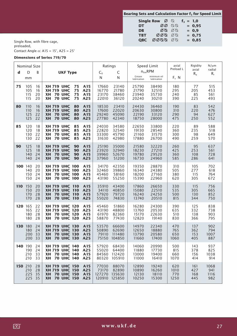
2437 UKF 26-27 22.08.2013 12:26 Uhr Seite 2
Probedruck
C M Y CM MY CY CMY K
Single Row, with fibre cage,preloaded,
Contact Angle α: A15 = 15°, A25 = 25°
Dimensions of Series 719/70
Greaselubrication
minimum oillubrication
nlimRPM
Speed LimitRatings Rigidity N/μmaxialPreload L axial radial
Nominal Size
105105115115
110110125125
120120130130
125125140140
140140150150
150150170170
165165180180
180180200200
190190210210
210210225225
16162020
16162222
18182222
18182424
20202424
20202828
22222828
24243333
24243333
28283535
38490325103573030210
36460308003312028000
33800285403157026700
32220272102952024960
28870243802716022960
26650225102425020510
24300205302263019140
22340188802058017400
20990177301940016410
19240162601811015300
25790217902394020240
24430206302219018750
22650191302116017880
21580182301978016730
19350163401820015390
17860150801624013740
16280137601517012820
14970126501379011660
14060118801300011000
12890108901213010250
XH 719XH 719XH 70XH 70
XH 719XH 719XH 70XH 70
XH 719XH 719XH 70XH 70
XH 719XH 719XH 70XH 70
XH 719XH 719XH 70XH 70
XH 719XH 719XH 70XH 70
XH 719XH 719XH 70XH 70
XH 719XH 719XH 70XH 70
XH 719XH 719XH 70XH 70
XH 719XH 719XH 70XH 70
UHCUHCUHCUHC
UHCUHCUHCUHC
UHCUHCUHCUHC
UHCUHCUHCUHC
UHCUHCUHCUHC
UHCUHCUHCUHC
UHCUHCUHCUHC
UHCUHCUHCUHC
UHCUHCUHCUHC
UHCUHCUHCUHC
75757575
80808080
85858585
90909090
100100100100
110110110110
120120120120
130130130130
140140140140
150150150150
17660167702317022010
18530176002924027780
24030228203330031630
25190239203996037960
34170324604546043190
3591034110
5792055020
45460431906197058870
53570508907911075150
57920550208456080320
7703073170
127270120910
23140217803846036120
23410220204509042340
34580325404579042980
35000329405267051200
42350398605816055250
43400408507972074830
51860488008236077430
6660062690111480104850
6843064400
112420105910
8807082890
135630125850
NC0
NCd D B
mm
UKF Type
Fv NRa
A15A25A15A25
A15A25A15A25
A15A25A15A25
A15A25A15A25
A15A25A15A25
A15A25A15A25
A15A25A15A25
A15A25A15A25
A15A25A15A25
A15A25A15A25
180295240390
190310290475
220360300490
260425360585
310505380620
330535500815
390635510830
470765650
1060
500815660
1070
6201010770
1250
7720585
225
8322094
250
8923598
259
95253108286
105277115305
115305130344
125332138366
137362153405
143378156414
161427168445
515453561493
542476627552
588518649570
637561728641
702618764672
756665852750
838738903795
902794
1007887
937825
1038914
1068941
1116982
Rr
Single Row f3 = 1,0
DT = 0,95
DB = 0,9
TBT = 0,75
QBC = 0,85
75
80
85
90
100
110
120
130
140
150
Bearing Sets and Calculation Factor f3 for Speed Limit
27w w w. u k f . d e

2437 UKF 28-29 22.08.2013 12:25 Uhr Seite 1
Probedruck
C M Y CM MY CY CMY K
UKF Spindle Bearings – Options
Shields
Certain bearings are available with optional, factory-installed shields. These bearings are also pre-lubricatedwith the appropriate type and quantity of grease, and areready for installation. In general, these bearings need noadditional lubricants during their service life. Shields areprovided on both sides, and are fixed in the Outer Ring.The shields are made of a special, exceptionally stabileplastic, which is resistant to most lubricants and againsttemperatures up to 80°C (180°F). The shields are non-contacting with the Inner Ring, and do not add any frictionload to the bearing.Shield designation: “2Z”, for ex. 719 UHC 50.A15.2Z.O/I.L
Lubrication
As an alternative to an axial lubricant supply using, forexample a distance ring (→ Distance Ring), lubricant canbe supplied radially, directly through the Outer Ring intothe raceway.The bearing is specially configured with an annular groovein the Outer Ring, which distributes the lubricant to severalradial bores. Additional grooves for O-ring seals areprovided to prevent unwanted lubricant migration.Lubricant feed designator: “LB” (lubrication bore), for ex.719 UHS 50.A15.LB.O/I.L
Variable Preload
A bearing’s preload determines both the performance ofthe spindle, as well as the quality of the product. Heavypreloads increase the rigidity of the bearing set; lightpreloads enable higher operating speeds.
On modern Machine Tools, especially Machining Centres,expanded speed ranges are often required to meetproductivity expectations. So, on the one hand, highrigidity for the working forces is required, on the otherhand high speeds for efficient High Speed Cutting isneeded.
The UKF VARIORING System varies the preload of a bearingfrom “light” to “medium” and “heavy”. This permits thehighest possible RPM, or high rigidity (stiffness),respectively, corresponding to the varying requirementsof the metal cutting operation. Only with bearings, whosepreload can be dynamically altered during operation, cana process or operation be fully optimized. Starting pointis normally a light preload.
UKF System VARIORINGHydraulic pressure is applied to a groove machined intothe outer ring of the bearing. Parallel O-ring grooves sealthe housing against the bearing ring, so that pressurecan be used to increase or decrease the effective fit, andinternal clearances of the bearing. The feature is applicableto any normal, double-row Spindle Bearing; usually withlight preload. No additional parts; no axial displacementof the shaft.
Type Series 718Bearings in accordance with these dimensions are availableon special order, and are subject to minimum orderrequirements.
p
28 w w w. u k f . d e

2437 UKF 28-29 22.08.2013 12:25 Uhr Seite 2
Probedruck
C M Y CM MY CY CMY K
29w w w. u k f . d e

2437 UKF 30-31 22.08.2013 12:21 Uhr Seite 1
Probedruck
C M Y CM MY CY CMY K
UKF Angular Contact Ball Bearings with Spacer Balls(rolling ball guidance) double row, preloaded – Series K, UK, UL, UM
Form factor according to DIN 628 part 5Rolling contact without sliding frictionBetween the two rows of load carrying balls, a third rowof row of smaller Spacer- or Guide-Balls, roll on a separateinternal bearing ring. The result is a bearing with onlyrolling friction at the load carrying balls—no tribologicallyadverse sliding friction resulting from a rigid cage! Thespace-saving effect of this unique design enables tworows of balls to occupy the same spaceas a comparably sized single row bearingbut with even more balls in each row!
Load Capacity and LifetimeThese bearings carry both radial and axialloads, and provide spherical contact ofthe balls (DF). This configuration providesa slight self-aligning preload; conse-quently, the balls remain under equal preload. The fullball complement also provides more load carrying pointsfor improved load capacity and lifetime.
Fig. 1: The inner ring has two races, Li1 and Li2; similarly,La1 and La2, are the outer races, formed by two rings,A1 and A2, which are locked together by the securityrings, V, fitted into machined grooves.
Fig. 2: When the inner ring rotates in direction of thearrow, the load carrying balls, T, follow in the samedirection and rotate as shown in the figure. In this example,the Spacer Balls, t, respectively, revolve around their axisas shown, due to their contact with the load-carryingballs. Similarly, the Guidance Ring, F, follows the guideballs, as shown.
Fig. 3: The load-carrying balls, T, are configured in twoparallel raceways (R1 and R2). However, instead of a rigidretainer, a third row of Spacer Balls simultaneously, GuideBalls, t maintains separation and guides the load carryingballs. The independently rotating Guidance ring, F, en-compasses the Spacer Balls and provides a preload. Thedesign is self-compensating, maintaining the preload
of the bearings!
The design is resistant to both the causesand the effects of wear. The bearings arefactory preloaded, and are ready for in-stallation without any further adjustment.
Dimensions are in accordance with di-mensional series 10, 20, 02, 03 / bearingseries 70, 72, 73. The K series bearings
are particularly advantageous, featuring a space savingd/D, when compared to the dimension series 10/bearingseries 70. Two rows within the dimensions of a singlerow bearing !
Accuracy is according to precision classes P5/ABEC 5…P2/ABEC 9, and even better with UKF-precision 0/0,respectively, HQ (see Running Precision).The cageless design (no rigid retainer) provides reducedwear, yielding longer running lifetimes while maintaininghigher running precision.
Bearings K/UK: Dimensions in accordance with Series 70
Bearings UL: Dimensions in accordance with Series 72
Bearings UM: Dimensions in accordance with Series 73
Reliable precision over along lifetime,
many load carrying balls,
ideal Spindle Bearing forheadstocks
30 w w w. u k f . d e
Figure 1
Figure 2 Figure 3

2437 UKF 30-31 22.08.2013 12:21 Uhr Seite 2
Probedruck
C M Y CM MY CY CMY K
nlimRPM
Speed Limit
Greaselubrication
minimum oillubrication
Ratings Seat DimensionsNominal Size Mass
C0 Cd D B UKF Type
N Nmm
ra da Da
mm
m
kg
40
42
47
55
60
62
67
68
72
75
80
85
90
92
95
100
105
110
110
115
120
125
125
130
135
140
140
145
150
160
170
175
180
195
210
225
235
250
260
280
300
14
14
15
16
17
17
18
18
19
19
20
21
22
22
22
23
24
24
25
24
26
27
28
27
30
30
32
30
34
36
38
39
40
40
42
45
48
52
52
55
58
8500
8500
7000
6000
5500
5500
5000
5000
4500
4500
3800
3600
3600
3400
3400
3000
2800
2800
2600
2600
2500
2500
2400
2400
2200
2200
2000
2000
1900
1800
1600
1500
1450
1300
1200
1150
1000
950
950
900
850
0,080
0,095
0,118
0,168
0,200
0,220
0,225
0,270
0,290
0,335
0,380
0,435
0,550
0,510
0,585
0,655
0,720
0,840
0,860
0,895
1,000
1,210
1,165
1,310
1,495
1,610
1,665
1,710
2,080
2,590
3,150
3,345
3,565
4,130
5,000
6,180
6,970
8,550
9,000
12,000
14,000
34
36
41
48
53
55
59
60
64
67
72
75
80
82
85
90
95
100
100
105
108
113
113
118
123
128
126
131
136
146
156
161
166
181
194
209
219
230
240
260
280
26
26
33
37
42
42
48
48
53
53
58
65
65
70
70
75
80
80
85
85
92
92
97
97
102
102
109
109
114
119
124
129
134
144
156
166
176
190
200
210
220
0,6
0,6
0,6
0,6
0,6
0,6
0,6
0,6
0,6
0,6
0,6
0,8
0,8
0,8
1,0
1,0
1,0
1,0
1,0
1,0
1,0
1,0
1,0
1,0
1,0
1,0
1,3
1,3
1,3
1,3
1,5
1,5
1,5
1,5
1,5
1,8
1,8
1,8
1,8
1,8
2,0
7000
7000
6000
5000
4500
4500
4000
4000
3500
3500
3200
3000
3000
2800
2800
2500
2300
2300
2200
2200
2100
2100
2000
2000
1800
1800
1700
1700
1600
1500
1300
1250
1200
1100
1000
950
850
800
800
750
700
K
UK
K
K
K
UK
K
UK
K
UK
K
K
UK
K
UK
K
K
UK
K
UK
K
UK
K
UK
K
UK
K
UK
K
K
K
K
K
K
K
K
K
K
K
K
K
20
20
25
30
35
35
40
40
45
45
50
55
55
60
60
65
70
70
75
75
80
80
85
85
90
90
95
95
100
105
110
115
120
130
140
150
160
170
180
190
200
9600
10200
13000
17300
20300
21300
24700
24700
27000
29500
32400
35000
41500
43500
46500
50500
52500
62500
56500
64800
67000
69500
72000
72000
89000
92000
89000
92000
109000
127000
136000
141000
146000
178000
201000
225000
241000
274000
287000
356000
401000
13300
13800
16900
21100
24400
25000
28400
28400
29900
33100
34600
36000
43200
44200
48000
50000
50800
60600
52200
61800
62400
63600
64800
64800
80400
82100
79200
81600
98400
113000
120000
121000
124000
148000
164000
182000
188000
214000
215000
271000
306000
20
25
30
35
40
45
50
55
60
65
70
75
80
85
90
95
100
105
110
115
120
130
140
150
160
170
180
190
200
Series K, UK
Dimensions: K = manufacturer’s standard UK = dimensional series 20 (d and D like Bearing Series 70)
Double Row, with rolling ball guidance (Spacer Balls),preloaded, Contact Angle α = 16°
a
a
ad
D
B
d
D
r
ar
31w w w. u k f . d e

2437 UKF 32-33 22.08.2013 12:21 Uhr Seite 1
Probedruck
C M Y CM MY CY CMY K
nlimRPM
Speed Limit
Greaselubrication
minimum oillubrication
Ratings Seat DimensionsNominal Size Mass
C0 Cd D B UKF Type
N Nmm
ra da Da
mm
m
kg
Dimensions: UL like Bearings of Series 72 UM like Bearings of Series 73
Double Row, with rotating Spacer Ballspreloaded,Contact Angle α = 16°
Series UL, UM
35
40
47
47
52
52
62
62
72
72
80
80
90
85
100
90
110
100
120
110
130
120
140
125
150
130
160
140
170
150
160
170
180
190
200
215
11
12
14
14
15
15
17
16
19
17
21
18
23
19
25
20
27
21
29
22
31
23
33
24
35
25
37
26
39
28
30
32
34
36
38
40
8500
8000
7000
7500
7000
6500
6000
5500
5000
5000
4500
4300
3800
3800
3400
3500
3100
3200
2900
3000
2800
2800
2400
2500
2300
2400
2200
2300
2100
2200
1900
1800
1700
1600
1400
1200
0,050
0,080
0,135
0,115
0,170
0,145
0,260
0,230
0,400
0,320
0,530
0,425
0,730
0,485
0,980
0,540
1,280
0,695
1,650
0,930
2,050
1,150
2,540
1,250
3,100
1,400
3,700
1,740
4,440
2,070
2,610
3,200
3,880
4,000
5,000
6,400
30
34
40
41
44
46
54
55
64
64
70
72
80
77
90
82
98
90
108
100
116
110
126
115
136
120
146
128
154
138
148
156
166
176
186
201
20
21
24
26
28
32
33
37
38
43
45
48
50
53
55
58
62
65
67
70
74
75
79
80
84
85
89
92
96
97
102
109
114
119
124
134
0,60
0,60
1,00
0,60
1,00
0,60
1,00
0,60
1,00
0,60
1,00
0,60
1,20
0,60
1,20
0,60
1,50
0,80
1,50
0,80
1,50
0,80
1,80
0,80
1,80
0,80
2,00
1,00
2,00
1,00
1,30
1,30
1,30
1,50
1,50
1,50
UL
UL
UM
UL
UM
UL
UM
UL
UM
UL
UM
UL
UM
UL
UM
UL
UM
UL
UM
UL
UM
UL
UM
UL
UM
UL
UM
UL
UM
UL
UL
UL
UL
UL
UL
UL
15
17
17
20
20
25
25
30
30
35
35
40
40
45
45
50
50
55
55
60
60
65
65
70
70
75
75
80
80
85
90
95
100
105
110
120
7800
12200
14200
14200
16500
17600
23000
23000
31100
29200
38500
34700
49500
40900
58500
45500
73000
52800
84500
61000
97000
69500
71000
76000
132000
83000
148000
93800
165000
110000
126000
144000
157000
176000
186000
219000
11500
14400
19600
19600
22300
23400
29800
28700
38400
34400
46200
39500
57000
45000
66600
49600
79800
55800
91200
62200
103000
69000
116000
75000
134000
80400
148000
88700
163000
102000
116000
131000
143000
148000
167000
193000
7000
6800
6100
6300
5700
5400
4900
4500
4100
4100
3700
3600
3200
3200
2800
2900
2600
2700
2400
2500
2300
2300
2000
2100
1900
2000
1800
1900
1700
1800
1600
1500
1400
1300
1200
1000
15
17
20
25
30
35
40
45
50
55
60
65
70
75
80
85
90
95
100
105
110
120
a
a
a
adD
B
r
d
D
r
32 w w w. u k f . d e

2437 UKF 32-33 22.08.2013 12:21 Uhr Seite 2
Probedruck
C M Y CM MY CY CMY K
33w w w. u k f . d e
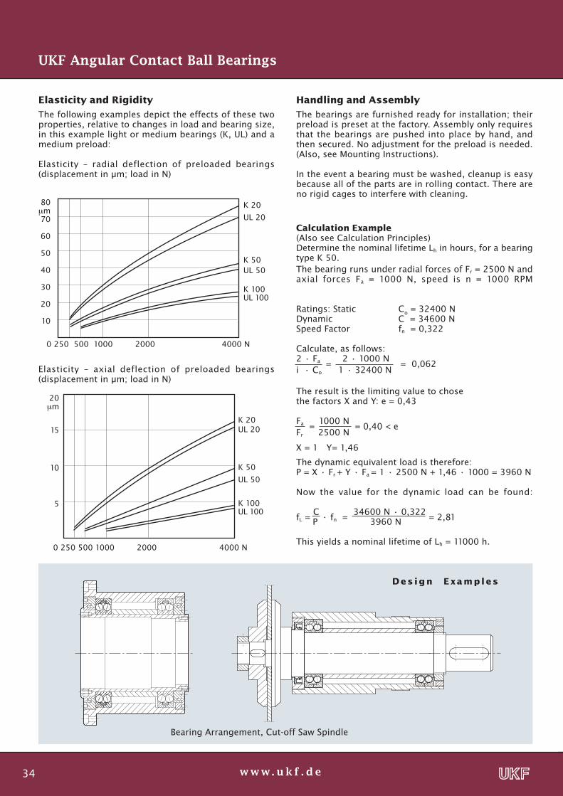
2437 UKF 34-35 22.08.2013 12:20 Uhr Seite 1
Probedruck
C M Y CM MY CY CMY K
0 250 500 1000 2000 4000 N
20μm
15
10
5
K 20UL 20
K 50
UL 50
K 100UL 100
80μm70
60
50
40
30
20
10
0 250 500 1000 2000 4000 N
K 20
UL 20
K 50UL 50
K 100UL 100
Elasticity and Rigidity
The following examples depict the effects of these twoproperties, relative to changes in load and bearing size,in this example light or medium bearings (K, UL) and amedium preload:
Elasticity – radial deflection of preloaded bearings(displacement in μm; load in N)
Handling and Assembly
The bearings are furnished ready for installation; theirpreload is preset at the factory. Assembly only requiresthat the bearings are pushed into place by hand, andthen secured. No adjustment for the preload is needed.(Also, see Mounting Instructions).
In the event a bearing must be washed, cleanup is easybecause all of the parts are in rolling contact. There areno rigid cages to interfere with cleaning.
Calculation Example(Also see Calculation Principles)Determine the nominal lifetime Lh in hours, for a bearingtype K 50.The bearing runs under radial forces of Fr = 2500 N andaxial forces Fa = 1000 N, speed is n = 1000 RPM
Ratings: Static Co = 32400 NDynamic C = 34600 NSpeed Factor fn = 0,322
Calculate, as follows:2 · Fa =
2 · 1000 N = 0,062
i · Co 1 · 32400 N
The result is the limiting value to chosethe factors X and Y: e = 0,43
Fa = 1000 N
= 0,40 < eFr 2500 N
X = 1 Y= 1,46
The dynamic equivalent load is therefore:P = X · Fr + Y · Fa = 1 · 2500 N + 1,46 · 1000 = 3960 N
Now the value for the dynamic load can be found:
fL = C
· fn
= 34600 N · 0,322
= 2,81 P 3960 N
This yields a nominal lifetime of Lh = 11000 h.
UKF Angular Contact Ball Bearings
Elasticity – axial deflection of preloaded bearings(displacement in μm; load in N)
D e s i g n E xa m p l e s
Bearing Arrangement, Cut-off Saw Spindle
34 w w w. u k f . d e

2437 UKF 34-35 22.08.2013 12:20 Uhr Seite 2
Probedruck
C M Y CM MY CY CMY K
Design Examples
High Frequency Turning Spindle designed with Spindle Bearings USS and USO
Surface Grinding Spindle using sealed High Speed Spindle Bearings UHS “2Z”
HSC-Spindle fitted with Spindle Bearings designed for direct lubrication “LB”
35w w w. u k f . d e

2437 UKF 36-37 22.08.2013 12:20 Uhr Seite 1
Probedruck
C M Y CM MY CY CMY K
Design Example
UKF Spindle Bearings for axially expanding shafts- Floating Bearing “AF..” with Ceramic Balls (Hybrid Bearings)
- Series 70 AFSC Single Row, 70 AFDC Double Row
The axial displacement permitted by a floating designposes special design considerations. Special attentionmust be given to the overall design in order to maximizethe performance of the floating bearing. Particularlyadvantageous is the application of a double row bearing,consisting of an outer assembly from an UKF USO bearing.This provides superior support, rigidity, and slidingcharacteristics.
Therefore, a double-row bearing with a cylindrical innersleeve was designed. The axial compensation is accom-plished entirely within the bearing itself, by allowing theInner Ring to slide relative to the outer assembly. Theseat in the housing remains unchanged. The bearingscan be produced with ceramic balls for high speeds; forlonger lifetimes with CRONIDEX®-steel inner rings, com-bined with stabile support of the shaft (two raceways anda one-part Outer Ring resist tilting). A conical bore providesa simple built-in adjustment; simply push onto the shaftuntil seat is tight, and free of play.
Single Row Design AFSCfor lower loads and high speeds
Options: Shields (2Z) with Grease Lubrication for life→ page 28
Direct Lubrication (LB)to the Outer Ring races→ page 28
At lower speed it is possible to
fit the bearings with steel balls.
100 Cr 6
CRONIDEX
N4Si3
Floating Bearing “AFDC”
70 AFDC double row
70 AF..one-part Inner- and Outer RingsCylindrical Inner RingAxially non-constraining,floating bearing design
36 w w w. u k f . d e

2437 UKF 36-37 22.08.2013 12:20 Uhr Seite 2
Probedruck
C M Y CM MY CY CMY K
nlimRPM
Speed Limit
Greaselubrication
minimum oillubrication
Ratings Seat DimensionsNominal Size Mass
C0 Cd D B UKF Type
N Nmm
ra da Da
mm
m
kg
One-part Inner- and Outer Rings,cylindrical bearing races on the Inner Ring CRONIDEX®- Floating Bearing with integrated Axial Displacement
UKF Floating BearingSeries AFSC, 70 AFDC
42
42
47
47
55
55
62
62
68
68
75
75
80
80
90
90
95
95
100
100
110
110
115
115
125
125
130
130
12
24
12
24
13
26
14
28
15
30
16
32
16
32
18
36
18
36
18
36
20
40
20
40
22
44
22
44
73600
69000
64000
60000
54400
51000
47200
44000
41600
39000
38400
36000
35200
33000
32000
30000
29600
27000
28000
26000
25600
24000
24000
22500
22400
21000
21600
20000
0,07
0,14
0.07
0.14
0,11
0,22
0,15
0,30
0,18
0,36
0,22
0,44
0,24
0,48
0,35
0,70
0,38
0,76
0,40
0,80
0,55
1,10
0,58
1,16
0,78
1,56
0,82
1,64
37,0
37,0
39,0
39,0
50,0
50,0
56,5
56,5
61,0
61,0
69,0
69,0
74,5
74,5
84,0
84,0
89,0
89,0
94,0
94,0
103,0
103,0
108,0
108,0
117,0
117,0
122,0
122,0
24,0
24,0
28,0
28,0
35,0
35,0
39,5
39,5
46,0
46,0
49,5
49,5
55,0
55,0
59,5
59,5
64,5
64,5
70,0
70,0
76,0
76,0
81,0
81,0
87,0
87,0
92,0
92,0
0,3
0,3
0,3
0,3
0,3
0,3
0,6
0,6
0,6
0,6
0,6
0,6
0,6
0,6
0,6
0,6
0,6
0,6
1,0
1,0
1,0
1,0
1,0
1,0
1,0
1,0
1,0
1,0
48000
45000
41600
39000
35200
33000
31200
29000
27200
25000
24800
23000
22400
21000
20000
18750
19200
18000
17600
16500
16000
15000
15200
14000
14400
13500
13600
12500
70 AFSC
70 AFDC
70 AFSC
70 AFDC
70 AFSC
70 AFDC
70 AFSC
70 AFDC
70 AFSC
70 AFDC
70 AFSC
70 AFDC
70 AFSC
70 AFDC
70 AFSC
70 AFDC
70 AFSC
70 AFDC
70 AFSC
70 AFDC
70 AFSC
70 AFDC
70 AFSC
70 AFDC
70 AFSC
70 AFDC
70 AFSC
70 AFDC
20
20
25
25
30
30
35
35
40
40
45
45
50
50
55
55
60
60
65
65
70
70
75
75
80
80
85
85
416
832
475
949
605
1209
800
1600
884
1768
1235
2470
1430
2860
1573
3146
1742
3484
1846
3692
2457
4914
2600
5200
3283
6565
3738
7475
4860
7560
5085
7910
6615
10290
8145
12670
8325
12950
11610
18060
12510
19460
12690
19740
14130
21980
14445
22470
18900
29400
19350
30100
25695
39970
27225
42350
20
25
30
35
40
45
50
55
60
65
70
75
80
85
a
a
a
Taper 1:12
d
D D
d
r
B
a
a Taper 1:12d
D D
d
B
AFSC AFDC
ar
ar
ar
ar
arar
ar
37w w w. u k f . d e

2437 UKF 38-39 26.08.2013 11:19 Uhr Seite 1
Probedruck
C M Y CM MY CY CMY K
Designs with flanges or collars
Bearings in various configurations(alternatively with Ceramic Balls …”C”)
Spindle BearingsLKSS (C)
Options:
Spindle BearingsLKSO (C)
High SpeedSpindle BearingsLKHS(C)
Spindle BearingsLSwith Spacer Balls
FASprings
SLAir Purge
TSTemperature-Monitoring
VSVibrationMonitoring
VRvariablepreloadVARIORING
FKliquid cooledjacket
UKF Bearing Cartridges
Integrated Bearing Set
preloaded
labyrinth seal
ready to assemble
38 w w w. u k f . d e

2437 UKF 38-39 22.08.2013 12:19 Uhr Seite 2
Probedruck
C M Y CM MY CY CMY K
UKF Bearing Cartridges
Cartridges are factory assembled Sets of Spindle Bearings,preloaded and greased, complete with applicable seals,ready for installation. This reduces parts count, as wellas manufacturing and assembly times, by combiningCovers, Seals, and Distance Rings into an easily installed,integrated assembly. Simply install the unit into a cylindricalbore in the applicable housing, and insert the shaft.
Sleeves are heat-treated steel, and are ground, includingthe outside diameter to the mounting face of the flangeor collar. This facilitates checking and justifying anyangular misalignment of the mount. Flanges are providedwith threaded jackscrew holes for easy removal, whilecover plates include an integrated labyrinth. Mating SplashRings are available for installation on the shaft.
Bearing Configurations
Various internal configurations are possible; these include2 x 2 rows (= Standard “2DB”) or “TBT, “QBC”, “QBT”, and“DB”. The bearings are spaced to provide rigidity and alarge span for supporting the shaft.
Cartridge Types
(P)LKSO… respectively, (P)LKSOC…assembled with Spindle Bearings 70 or 719,alternatively Hybrid Bearings with CeramicBalls (“…C”). Note: “P” Prefix indicates smallersleeve, reduced outer diameter; collar insteadof a flange.
Options
Cartridge configuration “TBT-FA”Spring loaded design: the third bearing’s Outer Ring isaxially loaded with springs to provide compensation forthe doubled preload of the front bearing pair, and toprevent migration of the third row.Sealing: either with lip seas or labyrinth; air purge isavailable with external connection, and with exhaustthrough the labyrinth.Sensors: for temperature and/or vibration, integrated inthe housing.Variable Preload: by applying hydrostatic pressure aroundthe Outer ring, between the bearing and the housing. Noadditional mechanical parts, higher preload available asneeded, simply switch on or off.
Special Design with liquid cooling: similar to water cooledspindle cartridges, the Bearing Cartridges can be designedwith cooling or heating capability, in order to maintainthermal equilibrium, such as in an air conditioned room.
Type LKLS, PLKLS
Featuring 2 x 2 track-bearings with Spacer Balls, preloaded,and a one-part Inner Ring, resulting in exceptional rigidityand maximum running accuracy. Inner Ring with the twobearings can also be supplied separately as “CartridgeSystem” (LS). Type “PLK…” with reduced outer diameterand a collar instead of a flange.For higher axial forces (e. g., drilling) an additional bearingfor axial forces can be provided.
Type LKLS
Type PLKHS
reduces parts and
working operations
shortens idle times
39w w w. u k f . d e

2437 UKF 40-41 22.08.2013 12:19 Uhr Seite 1
Probedruck
C M Y CM MY CY CMY K
UKF Bearing Cartridges – Bearings Series 719Series PLKSO, PLKSS with Spindle Bearings, PLKSOC with Hybrid Bearings
Series PLKHS with High Speed Spindle Bearings, PLKHC with Hybrid Bearings
d DUKF Type D1 d1
25
30
35
40
45
50
55
60
65
70
75
80
85
90
100
110
120
130
140
150
PLK S.
resp.
PLK H.
50
55
65
72
78
85
90
95
100
110
115
120
130
140
155
165
180
195
205
225
57
62
73
80
86
93
98
103
108
118
123
128
138
150
165
175
190
205
215
235
35
42
46
52
57
65
69
75
82
86
92
100
103
112
124
137
147
160
170
185
39
47
51
57
63
71
75
82
88
92
98
106
109
118
131
144
153
168
180
195
45
53
57
63
69
77
81
89
94
99
105
113
116
126
139
152
161
178
190
205
70
75,5
79,5
84,5
89
92
101
101
104
112
112
120
121
128
131
150
148
170
173
182
56
60
64
69
73
73
81
81
81
89
89
96
97
104
106
123
121
141
141
149
55
59
63
67
71
71
79
79
79
87
87
95
95
103
103
119
119
139
139
147
10
11,5
11,5
11,5
12
14
14,5
14,5
17
17
17
18
18
17
18
20
17
19
22
23
8
9
9
9
8
9
10
10
12
12
12
12
12
12
13
14
14
14
15
15
3
3,5
3,5
3,5
4
4
4
4
5
5
5
5
5
5
5
7
7
7
7
7
d2 d3 L L1 l a a1 a2
25
30
35
40
45
50
55
60
65
70
75
80
85
90
100
110
120
130
140
150
2,5
3
3,5
4
t b
5,1
6,1
7,1
8,1
with Labyrinth SealsPLKHC . . . QBC
with Labyrinth SealsPLKSO . . . 2DB
Outer sleeve available with a flange in lieu of collar
Possible bearing configurations
d
L
d+0.0
5
D 1d
1
L
l
a
a d
1
1+0.0
5
-0.1
d2
a2
+0.1
3
1D
...DB ...TBT ...QBC ...PBCt
Dimensions are in mm; external dimensions are maintained, regardless of internal bearing configuration:
b = groove width
40 w w w. u k f . d e

2437 UKF 40-41 22.08.2013 12:19 Uhr Seite 2
Probedruck
C M Y CM MY CY CMY K
LK S.
resp.
LK H.
UKF Bearing Cartridges – Bearings Series 70Series LKSO, LKSS with Spindle Bearings, LKSOC with Hybrid Bearings
Series LKHS with High Speed Spindle Bearings, LKHC with Hybrid Bearings
d DUKF Type D1 d1
25
30
35
40
45
50
55
60
65
70
75
80
85
90
95
100
110
120
130
140
150
62
68
72
80
90
95
105
110
120
125
130
140
150
160
170
180
200
210
230
250
270
85
95
95
105
125
130
140
150
160
165
170
180
190
200
215
225
245
255
280
300
320
35
42
46
52
57
65
69
75
82
86
92
100
103
112
116
124
137
147
160
170
185
39
47
51
57
63
71
75
82
88
92
98
106
109
118
123
131
144
153
168
180
195
45
53
57
63
69
77
81
89
94
99
105
113
116
126
130
139
152
161
178
190
205
71
78
82
90
105
111
120
128
137
143
148
160
168
177
190
200
220
230
255
270
290
70
75,5
79,5
84,5
89
92
101
101
104
112
112
120
121
128
129
131
150
148
170
173
182
55
59
63
67
71
71
79
79
79
87
87
95
95
103
103
103
119
119
139
139
147
10
11,5
11,5
11,5
12
14
14,5
14,5
17
17
17
18
18
17
17
18
20
17
19
22
23
8
9
9
9
8
9
10
10
12
12
12
12
12
12
12
13
14
14
14
15
14
3
3,5
3,5
3,5
4
4
4
4
5
5
5
5
5
5
5
5
7
7
7
7
7
d2 d3 T L1 l a a1 a2
50
53,5
57,5
61,5
67
66
74
73
75
81
80
88
89
95
95
96
109
108
127
126
135
M63 x 120º
Screw Size L
M83 x 120º
M103 x 120º
M104 x 90º
M124 x 90º
M125 x 72º
25
30
35
40
45
50
55
60
65
70
75
80
85
90
95
100
110
120
130
140
150
Countersunk for M…Cap Screw
with Labyrinth Seals
with Labyrinth SealsLKHC . . . QBC
LKSO . . . 2DB
Outer sleeve available with collar in lieu of flange
Possible bearing configurations
Dimensions are in mm; external dimensions are maintained, regardless of internal bearing configuration:
...DB ...TBT ...QBC
3d
+0.0
51
d
D d
1L
L
l
a1
da
+0.1
+0.0
5
d21
-0.1
2a
DT
1
41w w w. u k f . d e

2437 UKF 42-43 22.08.2013 12:18 Uhr Seite 1
Probedruck
C M Y CM MY CY CMY K
Screw Size
UKF Bearing CartridgesType LKLS
d DUKF Type D1 d1
25
30
35
40
45
50
55
60
65
70
75
80
85
90
95
100
105
110
120
130
140
150
25
30
35
40
45
50
55
60
65
70
75
80
85
90
95
100
105
110
120
130
140
150
62
68
72
80
90
95
105
110
120
125
130
140
150
160
170
180
190
200
210
230
250
270
85
95
95
105
125
130
140
150
160
165
170
180
190
200
215
225
235
245
255
280
300
320
35
42
46
52
57
65
69
75
82
86
92
100
103
112
116
124
130
137
147
160
170
185
39
47
51
57
63
71
75
82
88
92
98
106
109
118
123
131
136
144
153
168
180
195
45
53
57
63
69
77
81
89
94
99
105
113
116
126
130
139
144
152
161
178
190
205
71
78
82
90
105
111
120
128
137
143
148
160
168
177
190
200
210
220
230
255
270
290
60
66
66
61
72
80
87
87
95
100
105
110
118
125
133
140
150
157
160
172
184
195
45
50
50
50
55
60
65
65
70
75
80
85
90
100
105
110
120
125
130
140
160
160
10
11,5
11,5
11,5
12
14
14,5
14,5
17
17
17
18
18
17
17
18
18
20
17
19
22
23
8
9
9
9
8
9
10
10
12
12
12
12
12
12
12
13
14
14
14
14
15
14
3
3,5
3,5
3,5
4
4
4
4
5
5
5
5
5
5
5
5
6
7
7
7
7
7
d2 d3 T L1 l a a1 a2
40
44
44
44
50
54
60
59
66
69
73
78
86
92
99
105
114
116
120
129
137
148
M63 x 120º
L
M83 x 120º
M103 x 120º
M104 x 90º
M124 x 90º
M125 x 72º
LKLS
LKLS
LKLS
LKLS
LKLS
LKLS
LKLS
LKLS
LKLS
LKLS
LKLS
LKLS
LKLS
LKLS
LKLS
LKLS
LKLS
LKLS
LKLS
LKLS
LKLS
LKLS
D +0.0
5
d1d
d+0.0
5L
L1
l a
1
2
aa
D1
+0.1
-0.1
d3
d21
T
LKLS . . . 2 DF
with rolling guidance of ballsand Labyrinth Seals
Dimensions in mm
Countersunk for M… Cap Screw
42 w w w. u k f . d e

2437 UKF 42-43 22.08.2013 12:18 Uhr Seite 2
Probedruck
C M Y CM MY CY CMY K
UKF Bearing CartridgesType PLKLS
d DUKF Type D1 d1
25
30
35
40
45
50
55
60
65
70
75
80
85
90
95
100
105
110
120
130
140
150
25
30
35
40
45
50
55
60
65
70
75
80
85
90
95
100
105
110
120
130
140
150
55
65
68
75
80
90
95
100
110
115
122
132
138
150
155
165
180
190
200
215
235
250
60
70
75
80
85
95
100
105
115
120
130
140
145
160
165
175
190
200
210
225
245
260
35
42
46
52
57
65
69
75
82
86
92
100
103
112
116
124
130
137
147
160
170
185
39
47
51
57
63
71
75
82
88
92
98
106
109
118
123
131
136
144
153
168
180
195
45
53
57
63
69
77
81
89
94
99
105
113
116
126
130
139
144
152
161
178
190
205
60
66
66
61
72
80
87
87
95
100
105
110
118
125
133
140
150
157
160
172
184
195
45
50
60
50
55
60
65
65
70
75
80
85
90
100
105
110
120
125
130
140
160
160
10
11,5
11,5
11,5
12
14
14,5
14,5
17
17
17
18
18
17
17
18
18
20
17
19
22
23
8
9
9
9
8
9
10
10
12
12
12
12
12
12
12
13
14
14
14
14
15
14
3
3,5
3,5
3,5
4
4
4
4
5
5
5
5
5
5
5
5
6
7
7
7
7
7
d2 d3 L1 l a a1 a2
47
52
52
53
57
64
70
69
76
80
85
90
98
103
108
115
125
131
133
143
153
162
L
PLKLS
PLKLS
PLKLS
PLKLS
PLKLS
PLKLS
PLKLS
PLKLS
PLKLS
PLKLS
PLKLS
PLKLS
PLKLS
PLKLS
PLKLS
PLKLS
PLKLS
PLKLS
PLKLS
PLKLS
PLKLS
PLKLS
t b
2,3 4,1
2,5 5,1
3 6,1
3 7,1
+0.0
5d
D d
L
L1
l
a
a
a
t
PLK LS . . . 2 DF
D1
d+0.0
5
+0.1
-0.1
d3
d21
1
2
1
b = groove width
with rolling guidance of ballsand Labyrinth Seals
Dimensions in mm
43w w w. u k f . d e

2437 UKF 44-45 22.08.2013 12:31 Uhr Seite 1
Probedruck
C M Y CM MY CY CMY K
Mass
nlimRPM
Speed Limit
Greaselubrication
minimum oillubrication
Ratings
UKF Type kg
UKF Bearing CartridgesType LKLS, PLKLS
2 x 2 tracks with rolling guidance of ballsand Labyrinth Sealspreloaded, Contact Angle α = 16°
25
30
35
40
45
50
55
60
65
70
75
80
85
90
95
100
105
110
120
130
140
150
625568657268807590809590
10595
110100120110125115130122140132150138160150170155180165190180200190210200230215250235270250
63006300540054005000500045004500410041003400340032003200310031002700270025002500230023002200220021002100200020001800180017001700160016001400140013001300120012001100110010001000
5400540045004500410041003600360032003200290029002700270025002500230023002100210020002000190019001800180016001600150015001400140013001300120012001100110010001000900900800800
LKLS
PLKLS
LKLS
PLKLS
LKLS
PLKLS
LKLS
PLKLS
LKLS
PLKLS
LKLS
PLKLS
LKLS
PLKLS
LKLS
PLKLS
LKLS
PLKLS
LKLS
PLKLS
LKLS
PLKLS
LKLS
PLKLS
LKLS
PLKLS
LKLS
PLKLS
LKLS
PLKLS
LKLS
PLKLS
LKLS
PLKLS
LKLS
PLKLS
LKLS
PLKLS
LKLS
PLKLS
LKLS
PLKLS
LKLS
PLKLS
25
25
30
30
35
35
40
40
45
45
50
50
55
55
60
60
65
65
70
70
75
75
80
80
85
85
90
90
95
95
100
100
105
105
110
110
120
120
130
130
140
140
150
150
26000260003460034600406004060049500495005400054000645006450070000700008700087000
101000101000105000105000113000113000134000134000144000144000168000168000178000178000218000218000254000254000272000272000292000292000356000356000402000402000450000450000
3040030400378003780043900439005110051100
5380053800623006230064800648007950079500900009000091400914009390093900
112000112000117000117000143000143000145000145000177000177000203000203000216000216000223000223000266000266000295000295000328000328000
NC0
NCd D
mm
1,360,721,771,101,771,152,151,303,201,553,802,204,802,605,102,656,703,557,404,008,204,809,706,00
11,556,90
14,009,10
16,9510,1519,8012,3023,0014,9026,3018,5028,5020,4537,7028,3047,0032,9061,3039,90
LKLS
D d
PLKLS
D d
44 w w w. u k f . d e

2437 UKF 44-45 22.08.2013 12:31 Uhr Seite 2
Probedruck
C M Y CM MY CY CMY K
The Bearing Cartridges (P)LKSO and (P)LKHS,as described, are based on Spindle Bearings
but the Type LKLS and PLKLS contain,as a special feature, the Bearing Cartridge System LS.
UKF Bearing Cartridge Systems LS
Detailed description is provided under the Bearing Cart-ridges LKLS, PLKLS (→ table)
d DUKF Type D1 d1
25
30
35
40
45
50
55
60
65
70
75
80
85
90
95
100
105
110
120
130
140
150
25
30
35
40
45
50
55
60
65
70
75
80
85
90
95
100
105
110
120
130
140
150
47
55
60
67
72
80
85
92
100
105
110
120
125
135
140
150
160
170
180
195
210
225
35
42
46
52
57
65
69
75
82
86
92
100
103
112
116
124
130
137
147
160
170
185
40
48
52
59
64
72
75
82
90
95
100
108
113
123
126
136
146
156
166
180
192
208
45
50
50
50
55
60
65
65
70
75
80
85
90
100
105
110
120
125
130
140
150
160
L1
40
45
45
45
50
55
60
60
65
70
75
80
85
93
98
103
115
119
125
132
145
155
L
LS
LS
LS
LS
LS
LS
LS
LS
LS
LS
LS
LS
LS
LS
LS
LS
LS
LS
LS
LS
LS
LS
0,31
0,41
0,50
0,64
0,79
1,05
1,25
1,42
1,80
2,10
2,35
3,20
3,40
3,90
4,40
4,90
7,80
9,20
10,80
13,68
16,45
21,25
mkg
Bearing Cartridge System LS
Design Example
Bearing Cartridge LKSO 2 DB preloaded, with Distance Rings and Labyrinth Seal, ready for installation
Dimensions in mm
1d
-0.0
3
D
=
L
L
d
=
1d
+0.1
0+0.1
5
1
1
D
45w w w. u k f . d e

2437 UKF 46-47 22.08.2013 12:35 Uhr Seite 1
Probedruck
C M Y CM MY CY CMY K
UKFGrade
HQ
0
I
1, 1/2
ISO
2
4
5
DIN
P2
P4
P5
ABEC
9
7
5
Non-standardized, Ultra Precision
more precise than
Basically, UKF Spindle Bearings are manufactured tospecifications, which exceed the accepted standards.
Accuracy, Tolerances
Spindle Bearings and Bearing Cartridges are manufacturedin Precision Classes from UKF I (Standard) to UKF 0, oreven higher. Axial runouts of the inner ring (which is therotating part in most cases), to < 1 μm, (bore d < 50mm), in accordance with UKF precision „HQ“, are alsoavailable. For larger bore bearings, consult the factory.
UKF Angular Contact Ball Bearings with Spacer Balls aremade in the Precision Class 1/2 (Standard) or better.Higher precision is available per the table below; alsospecial precision, „HQ“, with radial runout to 1 μm,respectively, 1,5 μm. Consequently, it is possible tocombine various Inner/Outer ring accuracies to meetspecific requirements, e. g., UKF O/I, HQ/I, or others.
The dimensional accuracy (size tolerances), in combinationwith the running precision (classes), is shown in therespective tables. For especially challenging applications,bearings can be factory screened, such that all bearingsof a specific lot have no more than 2…3 μm variation inbore diameter.
The point of maximum runout (ring’s eccentricity), alongwith the size variation (actual measured deviation), ismarked on the bearing.
Bearing widths are, in general, manufactured to highertolerances than the standardized values for ΔBs, ΔCs.In case of specific tolerance requirements, please contactUKF.
ISO
2
4
5
DIN
P2
P4
P5
ABEC
9
7
5
Markings
To simplify volume production requirements, bearingscan be factory pre-sorted into matched Bearing Sets.Bearings can then be easily coordinated for best fit withthe other components of the assembly, to speed assemblyprocesses.
Reduced dimensional variation of d and D
12
1 2D
d
d d
D D
Δ Δ
Δ Δ
Dimensional tolerances and maximum runout Kia, Kea
Inner Ring
Kia = Radial Runout
Sia = Axial Runout
Sd = Orthogonality, ID to faceΔds = Variation of Bore diameter
to Nominal valueΔBs = Variation of width
to Nominal Value
VBs = Parallelism
Outer Ring
Kea = Radial Runout
Sea = Axial RunoutΔDs = Variation of Outer Diameter
to Nominal ValueΔCs = Variation of width
to Nominal Value (similar to ΔBs)
Designations according to DIN 620, DIN ISO 1132
46 w w w. u k f . d e

2437 UKF 46-47 22.08.2013 12:35 Uhr Seite 2
Probedruck
C M Y CM MY CY CMY K
Accuracy Grades
120 150 180 250 315 400
upon agreement
2,5 2,5 4 5 - -
2,5 2,5 5 7 - -
2,5 2,5 3 4 - -
5 5 5 6,5 8 10
5 5 5 6,5 8 10
upon agreement
4 5 5 7 - -
5 7 7 8 - -
4 5 5 6 - -
5 6 7 9,0 10 12
6 6 7 9 9 12
6 6 8 9 - -
9 10 10 13 - -
6 7 7 7 - -
9 10 13 15 18 20
11 13 14 15 18 20
6 6 8 9 - -
9 10 10 13 - -
6 7 7 7 - -
12 14 16 18 20 22
18 20 23 37 30 331)
otherwise as UKF 0 2)
otherwise as UKF I
up to
Kia
Kia
Sia
Sd
Kea
Sea
Kia
Kia
Sia
Sd
Kea
Sea
Kia
Sia
Sd
Kea
Sea
Kia
Sia
Sd
Kea
Sea
18
1
1,5
2
1,5
-
-
1
2,5
3
2
-
-
3,5
7
5
-
-
3,5
7
5
-
-
30
1
2
2,5
2
2,5
2,5
1
3
4
3
3
5
4
8
5
4
8
4
8
5
7
15
50
1
2
2,5
2
2,5
2,5
1
3
4
3
3
5
4
8
5
4
8
4
8
5
7
15
80
1,5
2,5
2,5
2
4
4
1,5
3
4
3
4
5
5
8
6
7
10
5
8
6
9
16
class
UKF HQ/01)
UKF 0/0
better
than
P 2/
ABEC 9
UKF HQ/I2)
UKF I/I
better
than
P 4 /
ABEC 7
UKF 1/1
better
than
P 5 /
ABEC 5
UKF 1/2
IR better
than
P 5/
ABEC 5
d/D in mm
Inner Ring (d)
Inner Ring (d)
Outer Ring (D)
Inner Ring (d)
Inner Ring (d)
Outer Ring (D)
Inner Ring (d)
Outer Ring (D)
Inner Ring (d)
Outer Ring (D)
120 150 180 250 315 400 -8 -10 -10 -12 - --100 -120 -140 -160 -180 - 4 5 5 6 7 - -8 -9 -10 -11 -13 -15
-6 -8 -8 -9 - --100 -120 -140 -160 -180 - 3 4 4 5 6 - -5 -5 -6 -8 -8 -10
Class
UKF 2UKF 1
UKF IUKF 0
d/D in mmIR (d) Δds
ΔBs
VBs
AR (D) Δds
IR (d) Δds
ΔBs
VBs
AR (D) ΔDs
Dimensional Accuracy, values in μm
bis0...0...0...0...
0...0...0...0...
18-5
-603-
-4-60
2-
30-5
-703
-6
-4-70
2-4
50-6
-803
-6
-4-80
2-4
80-7
-904
-7
-5-90
3-4
Running Precision, values in μm
47w w w. u k f . d e
iaK eaK
Cs
Bs
iaS eaSDS
dsd Ds
D
K
dsd
Cs
Bs
DS
D Ds
SiaS
eaKia
ea

2437 UKF 48-49 22.08.2013 12:36 Uhr Seite 1
Probedruck
C M Y CM MY CY CMY K
t1 cylindricity (DIN ISO 1101)
t2 wobble (DIN ISO 1101)
t3 co-axiality (DIN ISO 1101)
Ra surface finish (DIN 4768)
n·dm speed factors
dm average diameter of bearingdm = (d + D)/2
d1 kleiner Kegeldurchmesserd1 d = Nennmaß der Welle
d2 großer Kegeldurchmesserd2 = d1 + 0,08334 · L
L Kegellänge L = 0,95 · B(B = Lagerbreite)
ATD Kegelwinkeltoleranz alsDurchmesserdifferenzsenkrecht zur Achse
Form- und Lagetoleranzen sowie Mittenrauhwert wiebei zylindrischen Wellensitzen.
Kegelwinkel 4º 46’ 18,8’’Einstellwinkel 2º 23’ 9,4’’
Nominal dof shaftin mm
more upthan to
for grades UKF 1 and 2 for grades UKF I, O and HQtolerance
for dtolerance for d
n·dm in rpm · mm
≤ 1,2 ·106 > 1,2 · 106
values in μm
t1 t2t3
18
18 30
30 50
50 80
80 120
120 180
180
t1 t2t3
0- 5
0- 6
0- 7
0- 8
0- 9
0- 10
0- 12
Ra
1
1
1
1,5
1,5
2
3
2
2,5
2,5
3
3
4
5
6
8
8
9
9
10
12
+ 2- 2
+ 2- 2
+ 2- 3
+ 2- 3
+ 2- 4
+ 3- 5
+ 4- 6
0,5
0,5
0,5
0,8
0,8
1,5
2
1,2
1,5
1,5
2
2
3
4
4
5
5
6
6
8
10
0- 4
0- 4
0- 5
0- 5
0- 6
0- 8
0- 10
0,2
0,2
0,2
0,4
0,4
0,4
0,4
Kegeliger Wellensitz für AF-Lager
Nennmaßder Welle d
in mm
Abmaßfür d1
in μm
+ 73 + 91 + 108 + 135 + 159 + 193
+ 64 + 80 + 97 + 122 + 146 + 178
30
30
40
40
50
50
65
65
80
80
Nennmaß derKegellänge L
in mm
KegelwinkeltoleranzATD in μm
+ 2,0 + 2,5 + 3,0 0 0 0
25
25
40
40
über
bis
über
bis
48
Fit TolerancesShaft Seats
3 t /300 3 t /300
w w w. u k f . d e
1t
t 2 BA
RaRa
B
d
A
A
d
B
d2
2AT
D
L
d1
Kegel 1:12

2437 UKF 48-49 22.08.2013 12:36 Uhr Seite 2
Probedruck
C M Y CM MY CY CMY K
t1 cylindricity (DIN ISO 1101)
t2 wobble (DIN ISO 1101)
t3 co-axiality (DIN ISO 1101)
Ra surface finish (DIN 4768)
Installation
UKF Angular Contact Ball Bearings and SpindleBearings require proper installation andhandling, including cleanliness, as well asappropriate precision of the surroundingparts for maximum performance. As sup-plied, the bearings are prepared withcorrosion-resistant oil or pre-lubricated forlife with grease. If lubricating oils are used,the bearing(s) first have to be washed to avoidany cross-contamination. This is also neces-sary in case of re-lubrication with grease.
UKF spindle Bearings for universal arrange-ment/pairing can be combined to variousconfigurations. As the preload is alreadygiven ex works no special adjustment isnecessary.
Intermediate elements, such as Spacer Ringsor sleeves must be produced with flatnessand parallelism < 0,002 μm. The matingsurfaces (face) of lock nuts must be orthogo-nal to the thread axis.
When installing bearings, all bearings shouldbe aligned, such that their points of maximumeccentricity (marked on the bearing rings)are inline; both inner and out rings. This willprovide maximum accuracy for the assembly,and minimize wobble of the spindle.
Installation
Seats on shafts and in housings should becoated with a light film of compatible oil orgrease, before placing the bearings intoposition. Cover plates for fixing should havea sufficient number of screws, which aretorqued symmetrically to minimize distortionand runout errors.
The double row UKF Spindle Bearings (“USO”)feature a “one-piece Outer Ring”, withseparate, dual Inner Rings. To obtain thecorrect preload, simply lock the Inner Ringstightly against each other.
The required tightening torques of the locknuts depend on various conditions, includingbearing preload, size and pitch of the thread.The quality of the threads is also a significantfactor, so each application must be evaluatedseparately.
The one-piece outer ring, once engaged intothe housing’s bore, is easy to slide intoposition. This is advantageous for installati-ons, which require a floating bearing at oneend, to compensate for expansion andcontracting due to thermal effects.
When assembling bearings onto the shaft,respectively, into the housing, never use
Installation
force. In applications requiring a press fit,the bearing can first be warmed or cooled,as necessary, to facilitate installation. Ingeneral, temperatures of 80°…90°C aresufficient; temperatures higher than 110°Care to avoid! It is important to keep allcomponents square during assembly, andto apply symmetrical pressure against therings when assembling the spindle.
Attention: if bearing’s inside diameter, d, isnear its lower size limit, the shaft’s diametershould also be at the lower end. Similarly, ifthe bore diameter machined into the housingis finished at the upper end of tolerance, thena bearing with its tolerance of bearingdiameter, D, should also be at the higher end.
Dire assembly errors can usually detected byrotating the shaft. Intermittent binding orinconsistent rotation, are indications of anassembly mistake.
Another qualitative indicator for incorrectassembly is noise, emanating from therotating spindle. Error must be correctedimmediately.
values in μm
Nominal Dof borein mm
more upthan to
for grades UKF I, O und HQtolerance
for d
fixed floatingbearing bearing
for grades UKF 1 and 2tolerance
for d
fixed floatingbearing bearing
30
30 50
50 80
80 120
120 180
180 250
250 315
315
Ra
1,2
1,5
2
2,5
3
4
5
6
3
3
3
4
5
6
8
10
5
5
6
8
8
10
10
12
0,4
0,4
0,4
0,8
0,8
0,8
1,6
1,6
t1 t2t3t1 t2
t3
1
1,2
1,5
2
2,5
3
4
5
2
2
2
2,5
3
4
5
6
4
4
5
6
6
8
8
10
+ 5+ 2
+ 6+ 2
+ 8+ 2
+ 10+ 4
+ 14+ 5
+ 16+ 6
+ 20+ 8
+ 23+ 9
+ 3- 1
+ 3- 2
+ 4- 2
+ 5- 3
+ 6- 3
+ 8- 3
+ 10- 3
+ 10- 4
+ 7+ 2
+ 8+ 2
+ 10+ 2
+ 13+ 4
+ 17+ 5
+ 20+ 6
+ 23+ 8
+ 27+ 9
+ 4- 2
+ 4- 3
+ 5- 3
+ 6- 4
+ 8- 4
+ 10- 4
+ 12- 4
+ 13- 5
49
Fit TolerancesHousing Seats
w w w. u k f . d e
3
t 1
3
2t BA
Ra
t /300 B
D
A
Ra
t /300 A
Ra
Ra
D
B

2437 UKF 50-51 22.08.2013 12:37 Uhr Seite 1
Probedruck
C M Y CM MY CY CMY K
The necessary volume of oil per bearing is approx.1 ml/h, per 25 mm of bearing bore diameter. For theHigh Speed Bearings Type “UHS” and “UHC”, their pitchdiameter for oil injection is specified in the dimensionstable.
Grease
For grease lubrication, we recommend grease with a lowapparent or dynamic viscosity, i.e., with low consistencyin order minimize resistance to rotation.
As the result of many years experience, greases likeISOFLEX LDS 18 Special A and ISOFLEX NBU 15 for SpindleBearings, have been found to be well suited for our AngularContact Ball Bearings. (Messrs. Klüber: www.kluber.com).For very high RPM applications, especially with HybridBearings, we suggest TURMOGREASE High Speed L 252(Messrs. Lubcon: www.lubcon.com). But other qualifiedbearing greases, especially greases of NLG class 3 (forlower speed) and class 2 (for medium speed), with apenetration of 220…295, are usable.
Greases exhibiting high adhesion have demonstratedremarkable increases to the allowable speed limit, withouthaving to employ Oil-Air-devices. Additionally, the extracost for Hybrid Bearings becomes insignificant in relati-onship to the savings realized by eliminating additionalinfrastructure. UKF has many years of experience withHybrid Bearings and their handling, lubrication and cooling.
A guideline for the appropriate grease can be found withthis equation:
VF = dm2 · B · bF
VF = volume of grease, cm3
dm = average diameter (d+D)/2, cmB = width of bearing, cmbF = volume factor of grease (from table, below)
Notice: for bearings of Series “USO” and “AFDC” thecalculated quantity of grease is for each row of balls.
UKF bF
Type Series d ≤ 20 d=25..45 d=50..100 d > 100
719 UHS/UHC 0,079 0,052 0,043 0,03170 UHS/UHC 0,085 0,059 0,051 0,046719 USS(C)/USO(C) 0,049 0,037 0,034 0,03070 USS (C) USO (C) 0,064 0,048 0,039 0,036AFSC/AFDC 0,077 0,058 0,047 0,043K 0,012 0,008 0,007 0,006UK 0,015 0,011 0,009 -UL 0,014 0,013 0,011 0,010UM 0,013 0,012 0,008 -
Lubrication
UKF Angular Contact Ball Bearings and Spindle Bearingscan be lubricated with either oil (including oil-mist andminimal oil-air) or grease. Bearings are shipped with ananti-corrosive oil coating, or if specified, factory greased,ready for installation. (Specials, for dry running applica-tions, upon request.)
The double row Spindle Bearings of Type “USO” can befurnished with a bore through the Outer Ring for supplyinglubricants directly into the void between the raceways,and subsequently into the two bearing grooves. In thecase of grease lubrication, this void (space) can storesurplus grease away of the raceways.
Because some lubricants (grease, oil) are not compatiblewith each other, we recommend a thorough wash out
of the bearings, if the same products are not applied,especially if subsequent grease lubrication is proposed.
Oil
Oil lubrication, whether for high-speed (high RPM) opera-tion or for cooling, is integral to the overall spindle design,and may consist of circulating oil, atomizers, compressedair injection and even mechanical cooling devices, asrequired.
As the viscosity of oil is dependant on, among otherfactors, the temperature – under rising temperature itwill decrease – sufficient viscosity (operational viscosity)must be ensured at the normal working temperatures.For increasingly higher speeds, lower viscosity!
For example: A required operational viscosity of 12 mm2/s,combined with a normal working temperature of 40°C,requires a nominal viscosity of 9 mm2/s.
The nominal viscosity of an oil (in mm2/s at 50°C) can beobtained from the usual V-T-diagram. In general lubricatingoils with EP-additives, as per DIN 51517, etc., are recom-mended. For peak performance, lubrication systemsshould provide no more than 1 drop of oil/in 6 minutes,per 25 mm bore of bearing.
With minimal Oil Lubrication, very small quantities ofsuitable oil are adequate, but it must be carefully distri-buted, to ensure that the oil moistens the balls and thegrooves. Therefore, the nominal viscosity should not betoo low to achieve a sufficient covering of oil. The nominalviscosity should be near 25 mm2 at 50°C.
If a suitable operational temperature is not attained,another oil with higher or lower nominal viscosity shouldbe used.
50 w w w. u k f . d e

2437 UKF 50-51 22.08.2013 12:37 Uhr Seite 2
Probedruck
C M Y CM MY CY CMY K
For greased bearings, a routine warm-up is recommended.A warm-up period has a significant effect on bearing lifeand efficiency.
Warming up should proceed by gradually increasingspeeds, with the first one set at about 20 % of the maximumallowable speed. The spread between beginning andmaximum speed should then be divided into four steps,during the temperature should be monitored: subsequent,higher steps can follow as soon as the temperature hasstabilized.
Alternatively, a brief moderate-speed run to distribute thegrease, followed by a short ramp-up to speed and thenoff, again, culminating with a thermal equalization periodmay also be used. Although this more traditional warm-up is faster, it is not as conducive to long bearing life.
The working life of grease depends on various factors,including forces, vibration, contamination, humidity andtemperature – and, above all, the operating speed. Thefollowing diagram gives an overview of possible lubricantlifetimes, dependent on the characteristic value of speedn · dm as rpm · mm.
Lifetime LG of grease dependent on characteristicvalue of speed
Relubrication of grease
It is possible to improve the lifetime of the grease witha factor of 2 by using an automatical relubrication system.This micro electrical controlled unit can be connectedwith an extern CNC. As the result a relubrication of thebearings depending on the lifetime of the machine ispossible.
Temperature
High precision, super-finished races reduce friction andheat, and with time, they reduce wear and tear. Comparedwith paired single-row bearings, the UKF double-rowbearings have higher parallelism accuracy. The designcreates a void between the rows, which can effectivelyfunction as a grease reservoir. A similar configurationcan result by using UKF distance rings, for High SpeedBearings Types “UHS”, “UHC”.
Hybrid Bearings will run at lower temperatures thanbearings with steel balls, for the comparable speeds(RPM).
Friction
The preceding remarks about accuracy and runningcharacteristics, under “Temperature” also apply to friction.Bearings have three kinds of friction:
1. rolling friction between the balls and raceways2. sliding friction between balls and cages - and also
between cage and its guidance on the Inner- or OuterRing (rigid cage!)
3. viscous friction from the lubricant.
The inherent friction (resistance to rolling) in a rollingelement bearing is quite low, and is insignificant whencalculating fL, Lh.
Determining an optimal preload, careful selection oflubricants, and proper care during installation may furtherreduce friction.
Acoustic Noise
Noise can occur as the result of vibrations being trans-mitted through the components. Vibrations are usuallycaused by problems in the rotating parts, e. g., the naturalfrequency of the shaft with assembled bearings (-innerring, cage, balls). Appropriate design analysis shouldprevent such occurrences.
15000 h
0,1
5000 h
10000 h
20000 h
25000 h
0,5 1,0
n x d1,5 x 10
rpm x mm
6
L F
m
51w w w. u k f . d e

2437 UKF 52-53 22.08.2013 12:39 Uhr Seite 1
Probedruck
C M Y CM MY CY CMY K
Accuracy
In accordance with the requirements of Ball Screws, thebearings provide both high running precision and dimen-sional accuracy.
face runout Sd 2,0 μm at d ≤ 25 mm2,5 μm at d > 25 mm
tolerance I.D. Δds 0... -5 μmtolerance O.D. ΔDs 0... -10 μmtolerance width ΔBs 0... -250 μm
Ball Screws must provide high-load, bi-directional support,combined with high axial rigidity and excellent accuracy.With their unitized Outer Ring, similar to the well-knownUKF double-row Spindle Bearings, our GSX series providesan ideal solution.
Design: separate Inner Rings, self-contained with shieldsor seals, synthetic cages, high contact angle, α = 60°, andincreased number of balls, resulting in higher axial stiffnessand load capacity. The bearing’s rows are oriented in anO-configuration for high rigidity. Bearing preload is built-in at manufacture, and is realized whensecuring the Inner ring(s) to the shaft. GSXbearings can also be combined in pairedsets.
Cover Plate DG
Standardized parts provide easy and precise
installation, securing the bearing between the respectiveshoulders for bi-directional thrust loads.
Seals
Bearings and Bearing Cartridges with the designation“2RS” have lips seals. So a further sealing at the surroundingparts is not necessary. Bearings with the designation “2Z”have shields on both sides, with a gap at the rotatingInner Ring. This means less friction, suitable for higherspeeds (RPM).
Bearing Cartridges
Double row/four row Bearing Units are assembled intoflanged bushings to make production and installationeasier; eliminates having to generate a shoulder in arecessed hole. A cylindrical bore, with an orthogonal faceon the outside is much easier to produce.The ground cartridge (diameter and flange) allows theinstaller use it for checking the alignment. The flangehas a machined flat for offset mounting.
Option
For an even easier installation, and for ad-justing the tension of Ball Screws and thesupport Bearings of double-ended confi-gurations, additional washers, as shownbelow, can be furnished at extra charge.
bi-directional loads,installation usingbolt-on cover-plate orcomplete cartridges
Ball Screw Support Bearings
2Z
2RS
52 w w w. u k f . d e

2437 UKF 52-53 22.08.2013 12:39 Uhr Seite 2
Probedruck
C M Y CM MY CY CMY K
UKFType
Dimensions SeatDimensions
UKFType
for screws
nlimrpm
SpeedLimit
RatingsSeatingtorque
AxialPreload
Lock Nut Frictiontorque
Separa-ting-force
Axialrigidity
Tiltingrigidity Type
UKFType
Series GSX
d D d1
GSX
GSX
GSX
GSX
GSX
GSX
GSX
m
12
15
20
25
30
40
50
B min. D1 max. kg
12
15
20
25
30
40
50
42
45
52
57
62
75
90
25
25
28
28
28
34
34
16
20
25
32
40
50
63
33
37
43
48
53
67
81
0,20
0,21
0,31
0,34
0,39
0,61
0,88
D1 D2 b
DG
DG
DG
DG
DG
DG
DG
d
12
15
20
25
30
40
50
D3 Tk
65
70
75
80
85
105
120
42
45
52
57
62
75
90
33
37
43
48
53
67
80
10
10
10
10
10
12
14
M6
M6
M6
M6
M6
M8
M8
3 x 120º
3 x 120º
4 x 90º
4 x 90º
6 x 60º
6 x 60º
8 x 45º
52
55
62
67
72
89
104
C0 N Fv N MA Nm
GSX
GSX
GSX
GSX
GSX
GSX
GSX
12
15
20
25
30
40
50
24650
27900
46850
54800
64000
101000
125700
16900
17850
25900
27400
28750
42800
46450
960
1070
2050
2350
2650
3200
3700
2200
2450
4750
5500
6100
7250
8800
370
400
650
750
850
950
1250
50
65
135
190
280
550
950
NM 12 X
NM 15 X
NM 20 X
NM 25 X
NM 30 X
NM 40 X
NM 50 X
8
10
18
25
32
55
85
0,16
0,20
0,30
0,40
0,50
0,70
0,90
7600
7000
5400
4700
4300
3300
3000
0,08
0,10
0,15
0,20
0,25
0,35
0,45
3800
3500
3000
2600
2200
1800
1500
RK
Nm/m radC N MR Nm
2RS 2Z 2RS 2Z
Fd N Ra N/μm
DGGSX
d+0.1-0.022
-0.25B
b
D1
k
32
+0.1
D
±0.1
5T
-0.0
5-0
.02
D
Dd1 1
60º
D-0
.01
d-0
.005
53w w w. u k f . d e

2437 UKF 54-55 22.08.2013 12:40 Uhr Seite 1
Probedruck
C M Y CM MY CY CMY K
nlimrpm
SpeedLimit
RatingsSeatingtorque
AxialPreload
Lock Nut Frictiontorque
Separa-ting-force
Axialrigidity
Tiltingrigidity Type
UKFType
Drilled andCountersunk
Size Number
UKFType
FSX
FSX
FSX
FSX
FSX
FSX
FSX
Series FSX
L1 l aL
C0 N Fv N
12
15
20
25
30
40
50
24650
27900
46850
54800
64000
101000
125700
16900
17850
25900
27400
28750
42800
46450
960
1070
2050
2350
2650
3200
3700
2200
2450
4750
5500
6100
7250
8800
370
400
650
750
850
950
1250
50
65
135
190
280
550
950
NM 12 X
NM 15 X
NM 20 X
NM 25 X
NM 30 X
NM 40 X
NM 50 X
8
10
18
25
32
55
85
0,16
0,20
0,30
0,40
0,50
0,70
0,90
7600
7000
5400
4700
4300
3300
3000
0,08
0,10
0,15
0,20
0,25
0,35
0,45
3800
3500
3000
2600
2200
1800
1500
C N MR Nm2RS 2Z 2RS 2Z
kg
FSX
FSX
FSX
FSX
FSX
FSX
FSX
12
15
20
25
30
40
50
d d1
12
15
20
25
30
40
50
20
25
30
37
43
51
64
50
55
60
80
80
90
110
80
85
100
120
120
130
150
40
41
46
49
49
58
58
27
28
29
32
32
32
34
25
25
28
28
28
34
34
8
8
9
11
11
12
12
30
32
38
45
45
49
56
65
70
80
100
100
108
128
14
14
35
35
35
69
69
0,83
0,85
1,32
2,14
2,04
2,99
4,10
TD D1 A MAS
Nm
M6
M6
M8
M8
M8
M10
M10
6 x 54º
7 x 45º
6 x 54º
6 x 54º
7 x 45º
7 x 45º
8 x 33º 45'
Ra N/μm MA NmFd N RK
Nm/m rad
d-0
.005
d+0.1
T±0.1
1D1
1L
L
a l
1 Dh4
+0.1
d
A
DIN EN ISO 4762 (10.9) M. . .
for screws
A - A
A
A
FSX
54 w w w. u k f . d e

2437 UKF 54-55 22.08.2013 12:40 Uhr Seite 2
Probedruck
C M Y CM MY CY CMY K
SpeedLimit
RatingsSeatingtorque
AxialPreload
Lock Nut Frictiontorque
Separa-ting-force
Axialrigidity
Tiltingrigidity Type
UKFType
Drilled andCountersunk
Size Number
UKFType
FDX
FDX
FDX
FDX
FDX
FDX
FDX
L1 l aL
nlimrpmC0 N Fv N
12
15
20
25
30
40
50
49300
55800
93500
109500
128000
202000
251000
27400
28900
42000
44300
46500
69300
75200
960
1070
2050
2350
2650
3200
3700
4400
4900
9500
11000
12200
14500
17600
615
700
1150
1300
1500
1650
2200
110
145
310
430
580
1200
2250
NM 12 X
NM 15 X
NM 20 X
NM 25 X
NM 30 X
NM 40 X
NM 50 X
8
10
18
25
32
55
85
0,25
0,30
0,45
0,60
0,75
1,05
1,35
6000
5600
4300
3700
3400
2600
2400
0,16
0,20
0,3
0,40
0,5
0,7
0,9
3400
3100
2700
2300
2000
1600
1300
C N MR Nm2RS 2Z 2RS 2Z
kg
FDX
FDX
FDX
FDX
FDX
FDX
FDX
12
15
20
25
30
40
50
d d1
12
15
20
25
30
40
50
20
25
30
37
43
51
64
50
55
60
80
80
90
110
80
85
100
120
120
130
150
65
66
74
77
77
92
92
47
48
52
55
55
64
64
50
50
56
56
56
68
68
8
8
9
11
11
12
12
30
32
38
45
45
49
56
65
70
80
100
100
108
128
14
14
35
35
35
69
69
1,15
1,31
1,79
3,20
3,01
4,12
5,80
TD D1 A MAS
Nm
M6
M6
M8
M8
M8
M10
M10
6 x 54º
7 x 45º
6 x 54º
6 x 54º
7 x 45º
7 x 45º
8 x 33º 45'
Ra N/μm MA NmFd N
Series FDX
RK
Nm/m rad
A45°
Dh4
d1+
0.1
la
-0.0
05
d
1
TD1
±0.
+0.1
d
L 1
L
A - A
A
A
DIN EN ISO 4762 (10.9) M. . .
for screws
FDX
55w w w. u k f . d e

Design Examples
both ends supported with bearings GSX and AFDC (Floating Bearing)
only one end supported with bearings (cantilevered); Bearing Cartridge FDX
FSX FDX
56 w w w. u k f . d e

UKFType
Series 719
Dimensions in mm
Series 70
*) Specify Bearing Type and required width
UKFType
Dimensions in mm
for mounting the bearings with a specified separation,with feed holes for pneumatic oil lubrication or greasereservoir. Compatible with types 719/70 UHS resp. UHC
designed for shrink fit onto the shaft; contours matchthe labyrinth seals of our Bearing Cartridges; heat ringto expand for installation.
UKF Components
d De
DR
DR
DR
DR
DR
DR
DR
DR
DR
DR
DR
DR
DR
DR
DR
DR
DR
DR
DR
DR
DR
20
25
30
35
40
45
50
55
60
65
70
75
80
85
90
100
110
120
130
140
150
D
20
25
30
35
40
45
50
55
60
65
70
75
80
85
90
100
110
120
130
140
150
10
10
10
10
12
12
12
12
12
12
15
15
15
15
15
18
18
18
18
18
18
37
42
47
55
62
68
72
80
85
90
100
105
110
120
125
140
150
165
180
190
210
26,1
31,1
36,1
42,7
48,2
53,8
58,2
64,3
69,4
74,5
81,4
86,4
91,5
97,8
102,9
114,9
124,9
136,9
148,5
158,5
172,8
1,2
1,2
1,2
1,2
1,5
1,5
1,5
1,5
1,5
1,5
1,5
1,5
1,8
1,8
1,8
1,8
1,8
1,8
2,0
2,0
2,0
42
47
55
62
68
75
80
90
95
100
110
115
125
130
140
150
170
180
200
210
225
28,3
33,3
39,3
44,6
50,7
56,0
61,0
68,2
73,3
78,3
84,7
89,7
96,8
101,9
109,0
119,0
132,6
142,6
156,3
166,3
177,9
1,4
1,4
1,4
1,4
1,7
1,7
1,7
1,7
1,7
1,7
1,7
1,7
2,0
2,0
2,0
2,0
2,0
2,0
2,2
2,2
2,2
Bmin* ds DeD ds d
SR
SR
SR
SR
SR
SR
SR
SR
SR
SR
SR
SR
SR
SR
SR
SR
SR
SR
SR
SR
SR
SR
25
30
35
40
45
50
55
60
65
70
75
80
85
90
95
100
105
110
120
130
140
150
31
36
42
48
53
60
65
70
75
80
85
92
97
102
109
114
119
128
139
150
160
175
35
42
46
52
57
65
69
75
82
86
92
100
103
112
116
124
130
137
147
160
170
185
9,8
11,3
11,3
11,3
11,8
13,8
14,3
14,3
16,8
16,8
16,8
17,7
17,7
16,7
16,7
17,7
17,7
19,7
16,7
18,7
21,7
22,7
2
2
2
2
2,5
2,5
2,5
2,5
3
3
3
3
3
3
3
3
4
5
5
5
5
5
d1
6,5
7,5
7,5
7,5
6,5
7,5
8,5
8,5
10
10
10
10
10
10
10
11
12
12
12
12
13
13
39
47
51
57
63
71
75
82
88
92
98
106
109
118
123
131
136
144
153
168
180
195
45
53
57
63
69
77
81
89
94
99
105
113
116
126
130
139
144
152
161
178
190
206
d2 d3 a1 a2a
UKF Distance Ring DR UKF Splash Ring SR+0.0
3
+0.0
1
D
B
dD
-0.1
-0.0
5
-0.1
0
±0.1
sd
e +0.3
d2
-0.5
+0.5
3
-0.3
d
-0.5
-0.3
d1
d-0
.05
-0.0
3
2
1
a
15º
a
a
57w w w. u k f . d e

2437 UKF 58-59 22.08.2013 12:42 Uhr Seite 1
Probedruck
C M Y CM MY CY CMY K
UKF Lock Nuts NMA, NMB NMX
Form A
h
0,5
Form B
h
h1
D G D
M
b
t
D G D D1 1 2-0
,6-0
,7
D d G
0.5
1
h
b t
m
c
UKFType
Dimensions in mm
Lock Nut NM
Lock Nuts provide an easy and secure axial fastening ofbearings on a shaft. Form A needs less space; Form B isalso ideal for fastening Bearing Cartridges.Both have, depending on the size, two or three radial setscrews for securing.
Form X is mainly used if higher axial forces occur, e. g.,Support of Ball Screws. They have two set screws to guardagainst loosening.
UKFType
Dimensions in mm
UKF Components
NM
NM
NM
NM
NM
NM
NM
NM
NM
NM
NM
NM
NM
NM
NM
NM
NM
NM
NM
NM
NM
NM
39
46
51
58
63
71
74
81
89
94
99
107
111
120
125
134
140
147
157
170
180
195
31
38
43
48
53
58
65
70
75
80
85
92
97
102
109
114
119
124
134
144
156
166
2
2
2,5
3
3
3
2,5
3
3,5
4
3,5
3,5
4
4
4,5
5
5
5
5
5
5
5
6
6
6
6
7
7
7
8
8
8
8
8
9
9
10
10
10
11
12
12
12
12
35
42
46
52
57
65
69
75
82
86
92
100
103
112
116
124
130
137
147
160
170
185
D1 h h1G
M42 x 180º
12
12
12
13
14
15
16
17
18
18
18
18
20
20
22
25
26
26
26
28
28
28
6
6
6
7
7
8
9
9
10
10
10
10
11
11
13
14
14
14
15
15
15
15
6
7
7
8
8
8
10
10
10
10
10
10
10
10
12
12
12
12
12
12
12
12
M25 x 1,25
M30 x 1,25
M35 x 1,25
M40 x 1,25
M45 x 1,25
M50 x 1,25
M55 x 1,25
M60 x 1,25
M65 x 1,25
M70 x 1,25
M75 x 1,25
M80 x 1,25
M85 x 1,25
M90 x 1,25
M95 x 1,25
M100 x 1,25
M105 x 1,5
M110 x 1,5
M120 x 1,5
M130 x 1,5
M140 x 1,5
M150 x 1,5
D D2
A Bb t
M52 x 180º
M63 x 120º
M83 x 120º
M
NM
NM
NM
NM
NM
NM
NM
22
25
32
38
45
58
70
18
21
27
33
40
52
64
8
8
10
12
12
14
14
hd1G
4
4
5
6
6
7
7
M4
M4
M5
M6
M6
M6
M6
3
3
4
5
5
6
6
M12 x 1
M15 x 1
M20 x 1
M25 x 1,5
M30 x 1,5
M40 x 1,5
M50 x 1,5
D b t
12X
15X
20X
25X
30X
40X
50X
2
2
2
2
2
2,5
2,5
c m
25
30
35
40
45
50
55
60
65
70
75
80
85
90
95
100
105
110
120
130
140
150
58 w w w. u k f . d e

2437 UKF 58-59 22.08.2013 12:42 Uhr Seite 2
Probedruck
C M Y CM MY CY CMY K
UKF Special
Special Designs and Configurations
The UKF Range of Products enables us to offer a varietyof modifications to complement the Standard Types.
In lieu of the standard, fibre cage, solid cages (of brassor special plastic material) with dry-running capability foremergency cases are available. Of special interest are cagesof Polyetheretherketon (PEEK), a thermoplastic reinforcedby carbon fibre, and noted for high wear and temperatureresistance, combined with good sliding properties.
UKF Spindle Bearings can be made with a coated surface,for maintenance-free applications and extreme conditions,e. g., vacuums and space.
UKF Bearings and Bearing Cartridges can even be manuf-actured in larger sizes than shown in the tables: up to amax. O.D. of 380 mm.
Specially designed bearings with modified grooves,contoured to provide line contact, attain significantly higherload capacity. An example are bearings used for smoothlyadjusting transmission assemblies, even under higherworking forces.
Slim-line Spindle Bearings, double row and preloaded,with solid cage for very constrained spaces, e. g., d = 62,
D = 74, form USO.
Within the dimensions of an USO-Type Bearing (i. e., a pairof Single Row Bearings) a special construction is availableto place the bearing under an elastic preload usingcompression springs. Forces and numbers of springs arein accordance with the requirements.
To guard against corrosion, the bushings and cover platescan be plated: hard chrome, electro-less nickel, etc.Working forces can be monitored with sensors at thebearings. UKF Bearing Cartridges with integrated sensor
for working forces boast the same standard dimensionsas the regular models, with only the addition of a connec-ting cable!
The variable preload system, UKF VARIORING, can beintegrated into Bearing Cartridges “LKSO/LKSS”.
59w w w. u k f . d e

2437 UKF 60-61 22.08.2013 13:04 Uhr Seite 1
Probedruck
C M Y CM MY CY CMY K
Series 719 USS, 70 USS as a single bearing or in tandemarrangement (contact angle α = 21º)
Series 719 UHS/UHC... - A 15, 70 UHS/UHC...-A15(contact angle α = 15°)
as a single bearing or in tandem arrangement
for paired bearings in O or X arrangement
Series 719 UHS/UHC... - A 25, 70 UHS/UHC...-A25(contact angle α = 25°)
as a single bearing or in tandem arrangement
for paired bearings in 0 or X arrangement
fL values for spindle bearings and angular contact ball bearings
The fL-values are based on many years of experience, and are meantto serve as a guideline for new designs.
Dynamic rating C of bearing groups
For grouped bearings, factor fi is to be taken into consideration.
Cgroup = fi · Csingle [N]
fi = i0,7
i = number of bearings
In applications, where bearings of type USS are to be combined withtype USO, in tandem-O-arrangements, the dynamic rating of bearingtype USS is to be considered according to the following equation:
Cgroup = 2,36 · CUSS
By following this guidance, allowance is made for the fact that due tothe even load distribution, the rating of bearing type USO is higher thana pair of single bearings, type USS. Also in the case of double row orquadruple row bearing arrangements, USO type bearings should bepreferred to single row bearings.
Cgroup = 1,62 · CUSO for precision class UKF I/I and UKF 1/1
Cgroup = 1,80 · CUSO for precision class 0/0
application
turning and milling spindlesdrilling spindlesgrinding spindleswork head spindlescentrifugescircular sawscoating machinesspindles for machining centres
Nominal bearing life Lh
In order to determine the nominal bearing life, Lh, of a bearing arran-gement, the value of the dynamic load, fL, must first be calculated.
fL = C ·fn P
fL = symbol for the dynamic loadC = dynamic load rating [N]P = dynamic equivalent load [N]fn = speed factor
With the calculated value for fL, the nominal bearing life Lh in hours canbe determined from the table below. This is in accordance with theInternational Standard (DIN ISO 281) for a bearing failure rate probabilityof 10 %.
The actual length of services of a bearing, i. e., the running time inhours, depends on several factors. One factor is the operational runningcondition, e. g., flawless lubrication and prevention of any contamination,including coolants or debris. Finally, a perfect installation is an absolutenecessity.
Nominal bearing life Lh
X
1
Y X
0,72
Y
Intermediate values can be found with the following equation: Lh = 500 h · fL3
Dynamic equivalent load P
The dynamic equivalent load P is a compensation load for the bearing-life calculation. The dynamic equivalent load can be considered as aconstant radial loading, in magnitude and direction, under which acomparably loaded anti-friction bearing would actually reach the samelife limit.
P = X · Fr + Y · Fa
P = dynamic equivalent load [N]
Fr = radial load of the bearing [N]
Fa = thrust load of the bearing ]N]
X = radial factor
Y = axial factor
Factors X and Y are dependant on the contact angle. Increasing thrustload results in an increase of the ball contact angle, a (pressure angle).Hence, the thrust factor Y and the limiting value e depend on the ratiof0 · Fa/C0, at least in the case of a small contact angle (α <20°). ForBearings with a nominal contact angle of α ≥20°, the variation of theball contact angle resulting from higher thrust loads is negligible. Theradial factors as well as the thrust factors can be taken from the tablesbelow.
f0 = factor according to DIN ISO 76 taken from table below
C0 = static load rating of the single bearing
i = number of bearings
e = limiting value for Fa / Fr for selection of X and Y factors.
Series 719 USO, 70 USO, LK SO, PLK SOseries 719 USS, 70 USS in O- oder X-arrangement(contact angle α = 21º)
i
fi
2
1,62
3
2,16
4
2,64
e
0,57
X
1
Y
1,09
X
0,70
Y
1,63
Fa/Fr ≤ e Fa/Fr > e
e
0,57
X
1
Y
0
X
0,43
Y
1
Fa/Fr ≤ e Fa/Fr > e
X
1
Y
0
X
0,44
YFa/Fr ≤ e Fa/Fr > e
0,30,50,91,63,06,0
e
0,400,430,450,480,520,56
f0·Fa
i· C0
1,41,311,231,161,081
Fa/Fr ≤ e Fa/Fr > e
0,30,50,91,63,06,0
e
0,400,430,450,480,520,56
f0·Fa
C0
2,262,152,021,901,781,63
e
0,68
X
1
Y
0
X
0,41
Y
0,87
Fa/Fr ≤ e Fa/Fr > e
e
0,68
X
1
Y
0,92
X
0,67
Y
1,41
Fa/Fr ≤ e Fa/Fr > e
1,561,471,381,311,211,12
Calculation Principles
Lh (h)
500100020003000400050006000700080009000
fL
2,712,883,043,173,303,423,683,914,124,314,64
Lh (h)
1000012000140001600018000200002500030000350004000050000
fL
1,001,261,591,822,002,222,292,412,522,62
fL
3,0 - 4,53,0 - 4,02,5 - 3,53,5 - 4,52,5 - 3,02,0 - 3,03,0 - 4,03,5 - 4,5
60 w w w. u k f . d e

2437 UKF 60-61 22.08.2013 12:43 Uhr Seite 2
Probedruck
C M Y CM MY CY CMY K
precision f1
UKF HQ/0 UKF HQ/I 1,00UKF 0/0 UKF 0/I 1,00UKF I/I UKF 1/1 0,80UKF 1/2 1) 0,75
preload f2
L 1,00M 0,85S 0,65
VARIORING 1,00...0,65
bearing arrangement with single row bearings
DTDBTBTQBCwith double row USO bearings (TBT) and QBC combined with USS)DBTBTQBC
* with respect to nlim of the USO bearing
Static loading
Index of static stressing fS
The index of static stressing fS is a safety factor, against prohibitivepermanent deformations at the contact areas of balls. Since spindlebearings are required to perform well above the standards of generalmachine construction, the index of static stressing should be higherthan 2,5
fS = i · Co
Po
fS = index of static stressingCo = static load rating of the single bearing [N]i = number of bearingsPo = static equivalent load [N]
Static equivalent load Po
The static equivalent load is assessed by the equations:
Po = Xo · Fr + Yo· Fa und Po = FrThe higher of the two values is to be used.Po = static equivalent load [N]Fr = radial load of the bearing [N]Fa = thrust load of the bearing [N]]Xo = radial factorYo = axial factor
The factors Xo and Yo depend on the contact angle and the arrangementof the bearings.
Series 719 USS, 70 USS as a single bearing or in tandem arrangement(contact angle α = 21º)Xo = 0,5 Yo = 0,41
Series 719 USO, 70 USO, P/LK SO ...2DB, series 719 USS, 70 USSin O- or X arrangementXo = 1 Yo = 0,82
Series 719 UHS / UHC...-A 15, 70 UHS /UHC ...-A 15(contact angle α = 15º)
as a single bearing or in tandem arrangementXo = 0,5 Yo = 0,46
for paired bearings in O or X arrangementXo = 1 Yo = 0,92
Series 719 UHS /UHC...-A 25, 70 UHS / UHC ...-A 25(contact angle α = 25º)
as a single bearing or in tandem arrangementXo = 0,5 Yo = 0,38
for paired bearings in O or X arrangementXo = 1 Yo = 0,76
1) for series K, UK, UL, UM
load direction preload
radial1)
axial
axial
rigid or elastic (deflection)
rigid
elastic (deflection)1) valid only for pure radial load.
X
1
Y
1,621,571,531,461,411,371,291,231,141,12
X
0,72
Y
2,362,282,222,112,031,971,861,761,661,63
Fa/Fr ≤ e Fa/Fr ≥ ee
≤ 0,020,030,040,060,080,100,150,200,30
≥ 0,50
e
0,390,400,410,430,450,470,490,520,550,56
2Fa
C0
Fab/Fv y1 y2
02/311
1101
Combined loads
Applications in which varying loads and / or speeds occur, the meandynamic equivalent load Pm must be calculated, with respect to therespective duration of each individual running condition.
Pm = (P13 · n1 · q1 + P2
3 · n2 · q2 + ....Pn3 · nn ·qn)/(nm · 100%)
nm = (n1 · q1 + n2 · q2 + ....nn · qn) / 100%
Pm = mean dynamic equivalent load [N]
nm = mean speed [rpm]
P1 ... Pn = dynamic equivalent loads of the individual running conditions [N]
n1 ... nn = speeds of the individual running conditions [rpm]
q1 ... qn = periods of time of the respective running conditions [%]
Attainable speeds
The attainable speed or permissible speed, respectively, of a bearingarrangement depends on many factors which have a decisive influenceon the limiting speed. Therefore, only the most important ones, whichcan easily be calculated, are discussed.
nmax = f1 · f2 · f3 · nlim
nmax = maximum attainable speed [rpm]nlim = limiting speed to be taken from the table [rpm]f1 = precision factorf2 = preload factorf3 = arrangement factor
f3
10,950,90,750,85
0,9*0,85*0,8
Resultant thrust load
With preloaded spindle bearings, the resulting axial load is the reactionthrust load and the preload itself.
Fa = y1Fab + y2Fv
Fa = resulting thrust load [N]
Fab = external thrust load (operational load) [N]
Fv = preload [N]y1, y2 = correction factors
factor fo
Series K, UK, UL, UM, LK, PLK, LS
factor fo
Factor fo for series 719 UHS/UHC...-A 15, 70 UHS/UHC...-A 15(contact angle α = 15°)
Calculation Principles
dmm
2025303540455055606570
719 UHS/UHC
15,516,016,416,416,516,316,216,316,216,116,1
70 UHS/UHC
15,215,715,716,016,416,416,516,516,516,416,5
dmm
75808590100110120130140150
719 UHS/UHC
16,116,016,216,116,116,016,016,116,016,1
70 UHS/UHC
16,516,516,416,416,316,416,316,516,416,4
61w w w. u k f . d e

2437 UKF 62-63 22.08.2013 12:45 Uhr Seite 1
Probedruck
C M Y CM MY CY CMY K
Part Number Designation for UKF Spindle Bearingsand Angular Contact Ball Bearings with Spacer Balls
62
70 USO 65. A21. 2Z. I/1. 2DB. S
XH 719 USSC 120. A21. . O/I. DT. M
70 UHC 70. A15. LB. O/I. DB. L
70 AFDC 40. - . I/1.
UL 30. A16. I/1.Prefix
XH CRONIDEX®
Bearing Arrangement d in mm
Contact Angles α
A 21 α = 21º Standard of USS(C), USO(C)
A 15 α = 15º, A 25 α = 25º A15 Standard of UHS, UHCA 16 α = 16º A16 Standard of K, UK, UL, UMA ... Custom contact angles 12°…30° as per agreement
Preload
L light
M medium
S heavy
alternative:individual preload as per agreement
Precision Class
HQ better than at present given Standard
O better than ISO 2, P2, ABEC 9
I better than ISO4, P4, ABEC 7(Standard of Spindle Bearings)
1, 1/2 better than ISO5, P5, ABEC 5(Standard of Spindle Bearings with Spacer Balls)
Frequently precision of rotating Inner Ring isselected one grade higher than the Outer Ring.e. g., O/I (I.R/O.R)
Dimension Series
718 Ultra Light (on request)
719 Light
70 Medium
Bearing Arrangement
U = Single Bearing, universalDU = Set of two, universalBearing Sets → page 4
Options
2 Z (or ZZ) shields, with gap to I.R.
LB lubrication bore through Outer Ring
Additional Special Requirement
marked radial runout Outer Ringmarked radial runout Inner Ring
dimensional variation of i.D. and o.D.
range of ΔD1 upper halftolerance D/d ΔD2 lower half
Δd1 upper halfΔd2 lower half
and:greased on requestnoise checked on request
w w w. u k f . d e
< -3/-2 >
Type Series
Spindle Bearings/Hybrid Spindle Bearings
USS Standard Spindle Bearingssingle row, Steel Balls
USO Standard Spindle Bearingsdouble row DB, Steel Balls
USSC Hybrid Spindle Bearingssingle row, Ceramic balls
USOC Hybrid Spindle Bearingsdouble row DB, Ceramic balls
High Speed-/Hybrid-Spindle Bearings
UHS High Speed Spindle Bearingssingle row, Steel balls
UHC HS-Hybrid Spindle Bearingssingle row, Ceramic balls
Floating Bearings with cylindrical racewayson Inner Ring, ceramic balls
AFSC single rowAFDC double row
Angular Contact Precision Bearings with Spacer Balls
K/UK internal standard, dimensional series 02, Series 70
UL dimensional 02, Series 72
UM dimensional 02, Series 73

2437 UKF 62-63 22.08.2013 12:45 Uhr Seite 2
Probedruck
C M Y CM MY CY CMY K
Part Number Designation of UKF Bearing Cartridges
63
LKSS 70. TBT. A21. 0/I. S. FA/2Z
LKSOC 50. 2DB. A21. I/1. L. VR
PLKHC 45. DB. A15. HQ/0. L. XH/WK
PLKLS 60. 2DF. A16. I/1. M. VS
Layout
LK with flangeBearings Series 70
PLK with collarBearings Series 719
Bearing Assemblies
SS Spindle Bearings single row
SO Spindle Bearings double row
SSC similar single row Hybrid Bearings
SOC similar double row Hybrid Bearings
HS High Speed Single Bearings
HC High Speed Hybrid Bearings
LS Bearing System 2 x 2 rows
with Spacer Balls
Bore d in mm
Bearing Arrangement
DB 2 Spindle Bearings, O-ArrangementDF 2 Spindle Bearings, X-Arrangement
TBT 3 Spindle Bearings
QBC 4 Spindle Bearings
2DB 2 Spindle Bearings double row
2DF Bearing System LS
PBC 5 Spindle Bearings
Contact Angles α
A 21 α = 21º Standard of USS(C), USO(C)
A 15 α = 15º, A 25 α = 25º A15 Standard of UHS, UHCA 16 α = 16º A16 Standard of K, UK, UL, UMA ... Individual contact angles 12°…30° as per agreement
Options
FA preloading springsSL air purgeTS sensor for temperatureVS sensor for vibrationVR VARIORING
(variable preload)WK water coolingXH bearings of
CRONIDEX®-steel2Z shields at both sides,
with gap
Preload
L light
M or without designation= medium
S heavyalternative:
individual preloadas per agreement
Precision class
HQ better than at present given Standard
0 better than ISO 2, P2, ABEC 9
I better than ISO 4, P4, ABEC 7(Standard of Spindle Bearings)
1, 1/2 better than ISO 5, P5, ABEC 5(Standard of Bearings with Spacer Balls)
Frequently the precision of rotating Inner Ringis specified one grade higher than of Outer Ring,e. g., O/I. (I.R/O.R)
w w w. u k f . d e

2437 UKF 64-U3 22.08.2013 11:14 Uhr Seite 1
Probedruck
C M Y CM MY CY CMY K
64
UKF Angular Contact High Precision Ball Bearings, double row, preloaded,
with rotating guidance by Spacer Balls according to Series (…) beginning with bore d
1) Angle of contact at an optimum α = 21° (on request 12°...30°) 2) Double row Bearing in O-arrangement DB
*) for inner diameter d: ...00 = ∅ 10 mm ...03 = ∅ 17 mm
...01 = ∅ 12 mm ...04 = ∅ 20 mm
...02 = ∅ 15 mm ...05 = ∅ 25 mm etc.
Comparison of Bearings based on a size of bore d = 25 mm. Basic Types and additional markings.
Inch mm
0,00001 0,00025(1/4 μm)
0,0001 0,0025
0,0002 0,005
0,0003 0,0075
0,0004 0,010
0,0005 0,013
0,0007 0,018
Inch mm
0,001 0,025
0,003 0,075
0,004 0,100
0,005 0,1125
0,007 0,18
0,010 0,25
0,015 0,40
0,020 0,50
1/32 0,75
1/16 1,5
1,0 25,4
ºC ºF
0º 32º
50º 122º
100º 212º
kp lb
0,454 1
1,0 2,203
N kp
1 0,102
Measurement Units
Comparison of Ball Screw Support Bearings
7905...7905...SN 247905...DB7905...SN24...DB
7005...7005...SN247005...DB7005...SN24...DB
------
------
------
CA5V1V------
SEB25...SEB25/NS...SEB25...DDSEB25/NS...DD
EX25...EX25/NS...EX25...DDEX 25/NS...DD
VEB25...VEB25/NS...
VEX25...VEX25/NS...
------
...1
...3---
..../H1
..../XN
S 61905...HYS 61905S 61905...DBHYS 61905...DB
S 6005...HYS 6005...S 6005...DBHYS 6005...DB
------
------
------
CE
KH...------
71905...71905...HC...71905...DB71905...HC...DB
7005...7005...HC7005...DB7005...HC...DB
71905 CE...71905 CE/HC...
7005 CE...7005 CE/HC
------
CD or CEACD---------
B 71905...HCB 71905...B 71905...DBHCB71905..DB
B 7005...HCB 7005...B 7005...DBHCB 7005...DB
HS 71905...HC 71905...
HS 7005...HC 7005...
FD 1005...---
CE
2RSDDLRX....
Basic Types
719 USS 25 1)
719 USSC 25 1)
719 USO 25 1) 2)
719 USOC 25 1) 2)
70 USS 25 1)
70 USSC 25 1)
70 USO 25 1) 2)
70 USOC 25 1) 2)
719 UHS 25719 UHC 25
70 UHS 2570 UHC 25
70 AFSC 2570 AFDC 25
additional markings:A 15A 252ZLB
XH....
NSK-RHP *) SKF/SNFA GMN *) SKF *) INA/FAG *) UKF
ZKLN......
GSXFSXFDX
Internal standard (<70): K 20 ...
DIN 628-5 ( 70): UK 20 ...
DIN 628-5 ( 72): UL 15 ...
DIN 628-5 ( 73): UM 17 ...
Comparison of Bearing Types, Units of Measurement
w w w. u k f . d e

2437 UKF 64-U3 22.08.2013 11:14 Uhr Seite 2
Probedruck
C M Y CM MY CY CMY K
UKF Service
Design assistance and after sales consultancy, specific bearing selection, special designs
upon request. Evaluation, relubricating of your spare stock bearings.
Reconditioning of used bearing cartridges.
ISO 9001
Certified and audited No. 07-24024995
TÜV Munich/RKW Berlin
UKF delivers
ex works Berlin, overnight by air
or ex stock from our distributors
abroad in Europe, overseas, Far East.

2437 UKF U1-U4 26.08.2013 11:37 Uhr Seite 1
Probedruck
C M Y CM MY CY CMY K
Kienhorststraße 53 • D - 13403 Berlin (Reinickendorf)Tel.: ++49 (0)30. 41 00 04-0 • Fax ++49 (0)30. 413 20 46www.ukf.de • e-mail: [email protected]
UKF delivers ex works Berlin, overnight by air or ex stockfrom our distributors abroad in Europe, overseas, Far East.
UNIVERSAL-KUGELLAGER-FABRIK GMBH
www.ukf.de
High Precision Spindle Bearings
Angular Contact Ball Bearings with Spacer Balls
Bearing Cartridges
Ball Screw Support Bearings