Embed Size (px)
Citation preview
308–152Rev. H
Supersedes Fand PCN H
Includes Rev. G changes
First choice whenquality counts.�
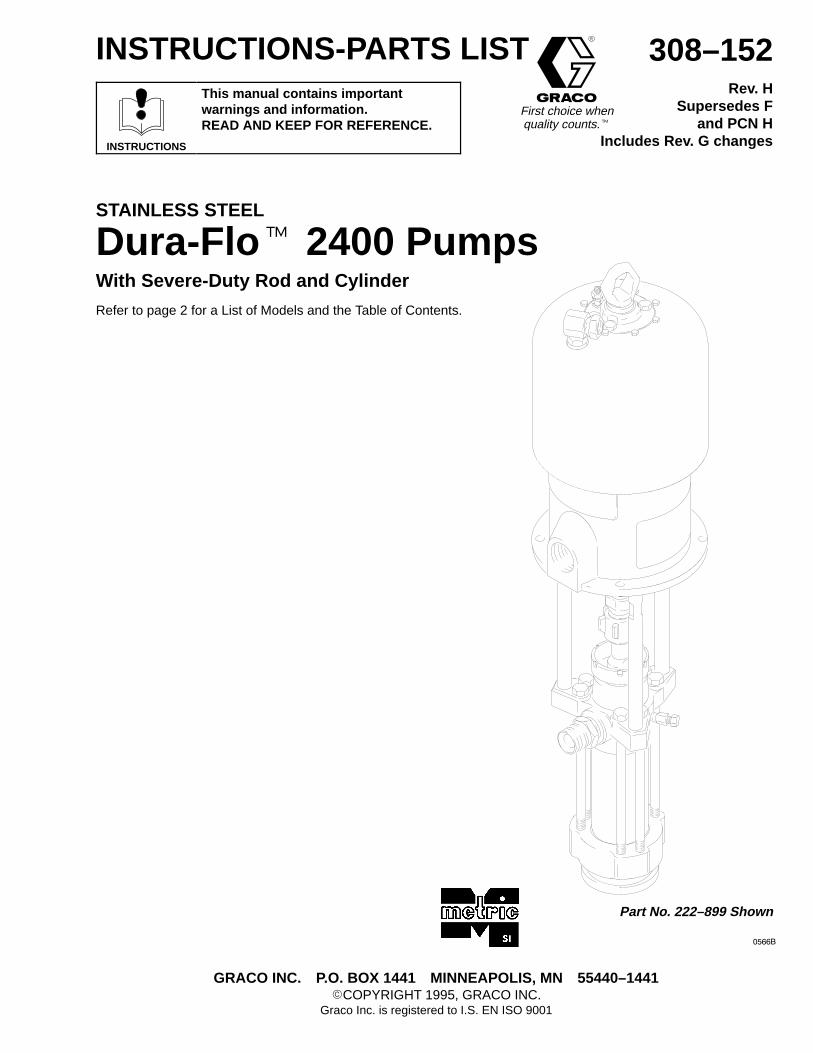
Part No. 222–899 Shown
�����
INSTRUCTIONS-PARTS LIST
INSTRUCTIONS
This manual contains importantwarnings and information.READ AND KEEP FOR REFERENCE.
STAINLESS STEEL
Dura-Flo� 2400 PumpsWith Severe-Duty Rod and Cylinder
Refer to page 2 for a List of Models and the Table of Contents.
GRACO INC. P.O. BOX 1441 MINNEAPOLIS, MN 55440–1441�COPYRIGHT 1995, GRACO INC.
Graco Inc. is registered to I.S. EN ISO 9001
� �������
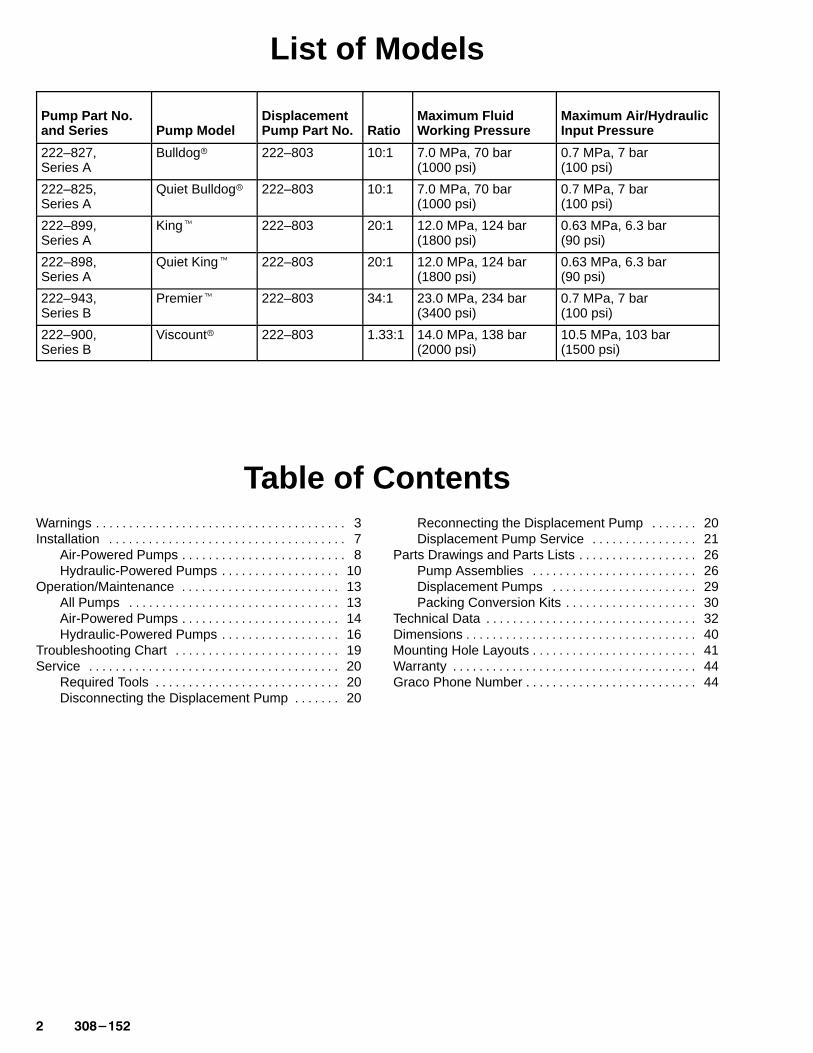
List of Models
Pump Part No.and Series Pump Model
DisplacementPump Part No. Ratio
Maximum Fluid Working Pressure
Maximum Air/HydraulicInput Pressure
222–827, Series A
Bulldog� 222–803 10:1 7.0 MPa, 70 bar(1000 psi)
0.7 MPa, 7 bar(100 psi)
222–825,Series A
Quiet Bulldog� 222–803 10:1 7.0 MPa, 70 bar(1000 psi)
0.7 MPa, 7 bar(100 psi)
222–899,Series A
King� 222–803 20:1 12.0 MPa, 124 bar(1800 psi)
0.63 MPa, 6.3 bar(90 psi)
222–898,Series A
Quiet King� 222–803 20:1 12.0 MPa, 124 bar(1800 psi)
0.63 MPa, 6.3 bar(90 psi)
222–943,Series B
Premier� 222–803 34:1 23.0 MPa, 234 bar(3400 psi)
0.7 MPa, 7 bar(100 psi)
222–900,Series B
Viscount� 222–803 1.33:1 14.0 MPa, 138 bar(2000 psi)
10.5 MPa, 103 bar(1500 psi)
Table of ContentsWarnings 3. . . . . . . . . . . . . . . . . . . . . . . . . . . . . . . . . . . . . . Installation 7. . . . . . . . . . . . . . . . . . . . . . . . . . . . . . . . . . . .
Air-Powered Pumps 8. . . . . . . . . . . . . . . . . . . . . . . . . Hydraulic-Powered Pumps 10. . . . . . . . . . . . . . . . . .
Operation/Maintenance 13. . . . . . . . . . . . . . . . . . . . . . . . All Pumps 13. . . . . . . . . . . . . . . . . . . . . . . . . . . . . . . . Air-Powered Pumps 14. . . . . . . . . . . . . . . . . . . . . . . . Hydraulic-Powered Pumps 16. . . . . . . . . . . . . . . . . .
Troubleshooting Chart 19. . . . . . . . . . . . . . . . . . . . . . . . . Service 20. . . . . . . . . . . . . . . . . . . . . . . . . . . . . . . . . . . . . .
Required Tools 20. . . . . . . . . . . . . . . . . . . . . . . . . . . . Disconnecting the Displacement Pump 20. . . . . . .
Reconnecting the Displacement Pump 20. . . . . . . Displacement Pump Service 21. . . . . . . . . . . . . . . .
Parts Drawings and Parts Lists 26. . . . . . . . . . . . . . . . . . Pump Assemblies 26. . . . . . . . . . . . . . . . . . . . . . . . . Displacement Pumps 29. . . . . . . . . . . . . . . . . . . . . . Packing Conversion Kits 30. . . . . . . . . . . . . . . . . . . .
Technical Data 32. . . . . . . . . . . . . . . . . . . . . . . . . . . . . . . . Dimensions 40. . . . . . . . . . . . . . . . . . . . . . . . . . . . . . . . . . . Mounting Hole Layouts 41. . . . . . . . . . . . . . . . . . . . . . . . . Warranty 44. . . . . . . . . . . . . . . . . . . . . . . . . . . . . . . . . . . . . Graco Phone Number 44. . . . . . . . . . . . . . . . . . . . . . . . . .
������� �
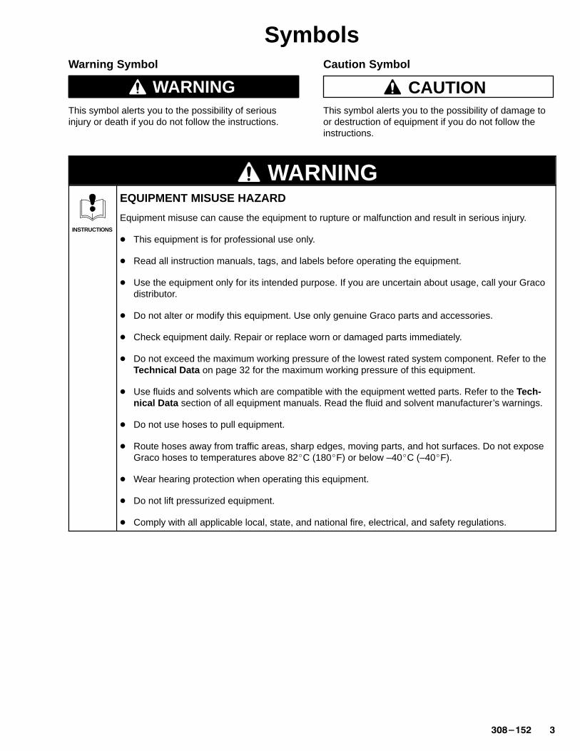
SymbolsWarning Symbol
WARNINGThis symbol alerts you to the possibility of seriousinjury or death if you do not follow the instructions.
Caution Symbol
CAUTIONThis symbol alerts you to the possibility of damage toor destruction of equipment if you do not follow theinstructions.
WARNING
INSTRUCTIONS
EQUIPMENT MISUSE HAZARD
Equipment misuse can cause the equipment to rupture or malfunction and result in serious injury.
� This equipment is for professional use only.
� Read all instruction manuals, tags, and labels before operating the equipment.
� Use the equipment only for its intended purpose. If you are uncertain about usage, call your Gracodistributor.
� Do not alter or modify this equipment. Use only genuine Graco parts and accessories.
� Check equipment daily. Repair or replace worn or damaged parts immediately.
� Do not exceed the maximum working pressure of the lowest rated system component. Refer to theTechnical Data on page 32 for the maximum working pressure of this equipment.
� Use fluids and solvents which are compatible with the equipment wetted parts. Refer to the Tech-nical Data section of all equipment manuals. Read the fluid and solvent manufacturer’s warnings.
� Do not use hoses to pull equipment.
� Route hoses away from traffic areas, sharp edges, moving parts, and hot surfaces. Do not exposeGraco hoses to temperatures above 82�C (180�F) or below –40�C (–40�F).
� Wear hearing protection when operating this equipment.
� Do not lift pressurized equipment.
� Comply with all applicable local, state, and national fire, electrical, and safety regulations.
� �������
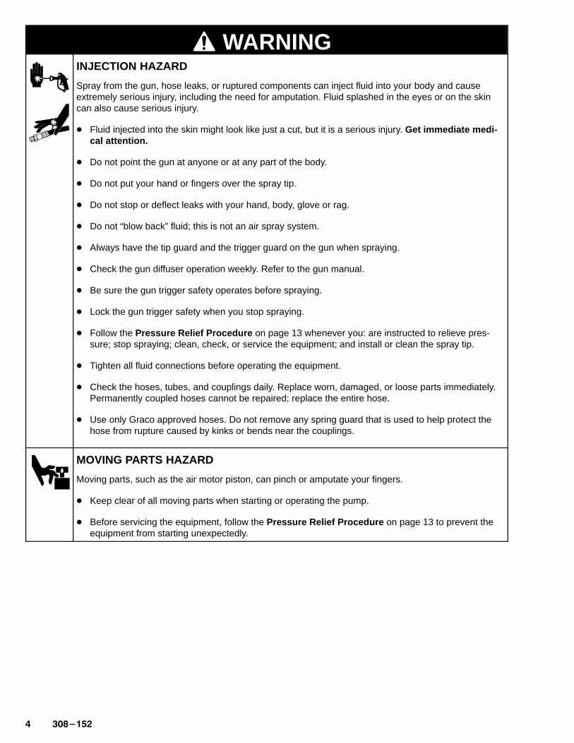
WARNINGINJECTION HAZARD
Spray from the gun, hose leaks, or ruptured components can inject fluid into your body and causeextremely serious injury, including the need for amputation. Fluid splashed in the eyes or on the skincan also cause serious injury.
� Fluid injected into the skin might look like just a cut, but it is a serious injury. Get immediate medi -cal attention.
� Do not point the gun at anyone or at any part of the body.
� Do not put your hand or fingers over the spray tip.
� Do not stop or deflect leaks with your hand, body, glove or rag.
� Do not “blow back” fluid; this is not an air spray system.
� Always have the tip guard and the trigger guard on the gun when spraying.
� Check the gun diffuser operation weekly. Refer to the gun manual.
� Be sure the gun trigger safety operates before spraying.
� Lock the gun trigger safety when you stop spraying.
� Follow the Pressure Relief Procedure on page 13 whenever you: are instructed to relieve pres-sure; stop spraying; clean, check, or service the equipment; and install or clean the spray tip.
� Tighten all fluid connections before operating the equipment.
� Check the hoses, tubes, and couplings daily. Replace worn, damaged, or loose parts immediately.Permanently coupled hoses cannot be repaired; replace the entire hose.
� Use only Graco approved hoses. Do not remove any spring guard that is used to help protect thehose from rupture caused by kinks or bends near the couplings.
MOVING PARTS HAZARD
Moving parts, such as the air motor piston, can pinch or amputate your fingers.
� Keep clear of all moving parts when starting or operating the pump.
� Before servicing the equipment, follow the Pressure Relief Procedure on page 13 to prevent theequipment from starting unexpectedly.
������� �
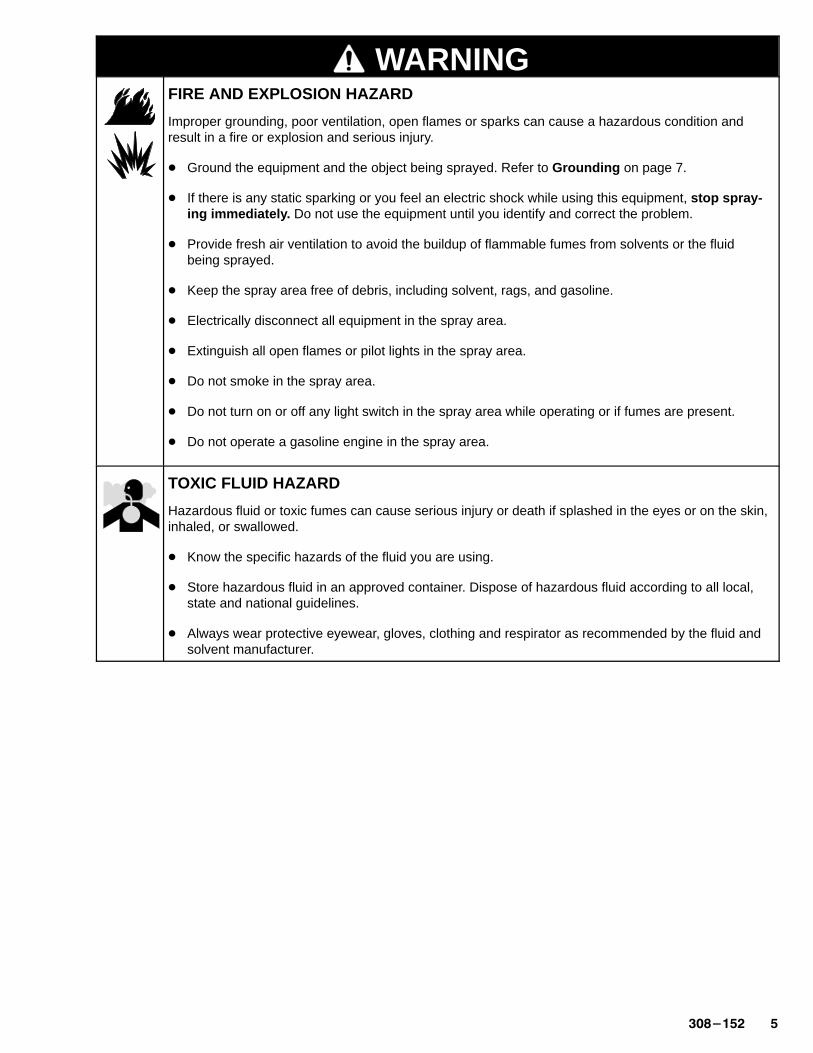
WARNINGFIRE AND EXPLOSION HAZARD
Improper grounding, poor ventilation, open flames or sparks can cause a hazardous condition andresult in a fire or explosion and serious injury.
� Ground the equipment and the object being sprayed. Refer to Grounding on page 7.
� If there is any static sparking or you feel an electric shock while using this equipment, stop spray-ing immediately . Do not use the equipment until you identify and correct the problem.
� Provide fresh air ventilation to avoid the buildup of flammable fumes from solvents or the fluidbeing sprayed.
� Keep the spray area free of debris, including solvent, rags, and gasoline.
� Electrically disconnect all equipment in the spray area.
� Extinguish all open flames or pilot lights in the spray area.
� Do not smoke in the spray area.
� Do not turn on or off any light switch in the spray area while operating or if fumes are present.
� Do not operate a gasoline engine in the spray area.
TOXIC FLUID HAZARD
Hazardous fluid or toxic fumes can cause serious injury or death if splashed in the eyes or on the skin,inhaled, or swallowed.
� Know the specific hazards of the fluid you are using.
� Store hazardous fluid in an approved container. Dispose of hazardous fluid according to all local,state and national guidelines.
� Always wear protective eyewear, gloves, clothing and respirator as recommended by the fluid andsolvent manufacturer.

� �������
Notes
������� �
Installation(ALL PUMPS)
NOTE: Reference numbers and letters in parenthesesin the text refer to the callouts in the figures and theParts Drawing.
NOTE: Always use Graco Parts and Accessories,available from your Graco distributor. If you supplyyour own accessories, be sure they are adequatelysized and pressure rated for your system.
The Typical Installation shown on page 8 is only aguide for selecting and installing system componentsand accessories. Contact your Graco distributor forassistance in designing a system to suit your particularneeds.
Grounding
WARNINGFIRE AND EXPLOSION HAZARDBefore operating the pump, ground thesystem as explained below. Also readthe section FIRE AND EXPLOSIONHAZARD on page 5.
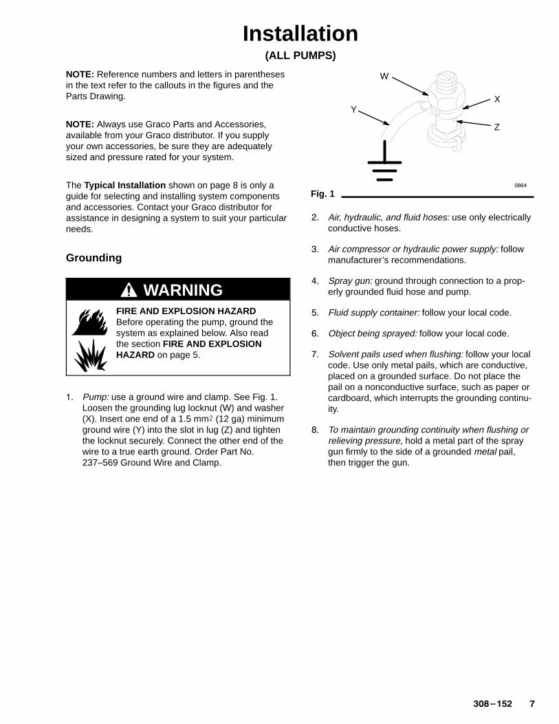
�� Pump: use a ground wire and clamp. See Fig. 1.Loosen the grounding lug locknut (W) and washer(X). Insert one end of a 1.5 mm� (12 ga) minimumground wire (Y) into the slot in lug (Z) and tightenthe locknut securely. Connect the other end of thewire to a true earth ground. Order Part No.237–569 Ground Wire and Clamp.
Fig. 1
W
XY
Z
���
�� Air, hydraulic, and fluid hoses: use only electricallyconductive hoses.
�� Air compressor or hydraulic power supply: followmanufacturer’s recommendations.
�� Spray gun: ground through connection to a prop-erly grounded fluid hose and pump.
�� Fluid supply container: follow your local code.
�� Object being sprayed: follow your local code.
� Solvent pails used when flushing: follow your localcode. Use only metal pails, which are conductive,placed on a grounded surface. Do not place thepail on a nonconductive surface, such as paper orcardboard, which interrupts the grounding continu-ity.
� To maintain grounding continuity when flushing orrelieving pressure, hold a metal part of the spraygun firmly to the side of a grounded metal pail,then trigger the gun.
� �������
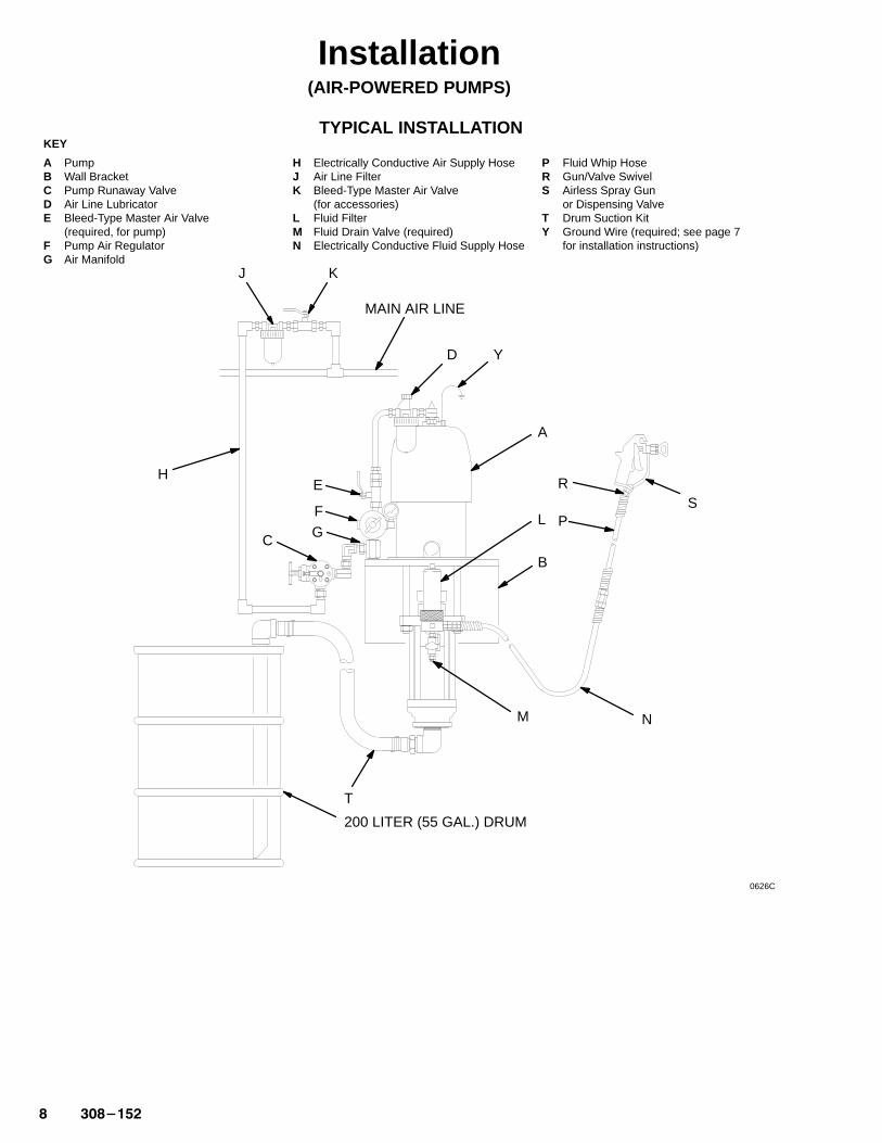
Installation(AIR-POWERED PUMPS)
KEY
A PumpB Wall BracketC Pump Runaway ValveD Air Line LubricatorE Bleed-Type Master Air Valve
(required, for pump)F Pump Air RegulatorG Air Manifold
H Electrically Conductive Air Supply HoseJ Air Line FilterK Bleed-Type Master Air Valve
(for accessories)L Fluid FilterM Fluid Drain Valve (required)N Electrically Conductive Fluid Supply Hose
P Fluid Whip HoseR Gun/Valve SwivelS Airless Spray Gun
or Dispensing ValveT Drum Suction KitY Ground Wire (required; see page 7
for installation instructions)
A
B
C
D
E
F
G
H
J K
M N
P
Y
MAIN AIR LINE
200 LITER (55 GAL.) DRUM
L
RS
T
TYPICAL INSTALLATION
0626C

������� �
Installation(AIR-POWERED PUMPS)
System Accessories
WARNINGA bleed-type master air valve (E) and a fluid drainvalve (M) are required in your system. Theseaccessories help reduce the risk of serious injury,including fluid injection and splashing of fluid in theeyes or on the skin, and injury from moving parts ifyou are adjusting or repairing the pump.
The bleed-type master air valve relieves air trappedbetween this valve and the pump after the air isshut off. Trapped air can cause the pump to cycleunexpectedly. Locate the valve close to the pump.Order Part No. 107–141.
The fluid drain valve assists in relieving fluid pres-sure in the displacement pump, hose, and gun.Triggering the gun to relieve pressure may not besufficient. Order Part No. 210–658.
Air and Fluid Hoses
Be sure all air hoses (H) and fluid hoses (N and P) areproperly sized and pressure-rated for your system.Use only electrically conductive hoses. Use a whiphose (P) and a swivel (R) between the main fluid hose(N) and the gun/valve (S) to for easier gun/valvemovement.
Mounting Accessories
Mount the pump (A) to suit the type of installationplanned. The Typical Installation on page 8 illus-trates a wall-mounted system. Pump dimensions andthe mounting hole layout are shown on pages 40 and41.
If you are using an elevator or a cart, refer to theseparate manuals supplied with those components forinstallation and operation instructions.
Air Line Accessories
Install the following accessories in the order shown inthe Typical Installation on page 8, using adaptersas necessary.
� An air line lubricator (D) provides automatic airmotor lubrication.
� A bleed-type master air valve (E) is required inyour system to relieve air trapped between it andthe air motor when the valve is closed (see theWARNING) at left. Be sure the bleed valve is easilyaccessible from the pump, and is located down-stream from the air regulator.
� An air regulator (F) controls pump speed andoutlet pressure by adjusting the air pressure to thepump. Locate the regulator close to the pump, butupstream from the bleed-type master air valve.
� A pump runaway valve (C) senses when thepump is running too fast and automatically shuts offthe air to the motor. A pump which runs too fast canbe seriously damaged.
� An air manifold (G) has a swivel air inlet. Itmounts to a wall bracket, and provides ports forconnecting lines to air-powered accessories.
� An air line filter (J) removes harmful dirt andmoisture from the compressed air supply.
� A second bleed-type air valve (K) isolates the airline accessories for servicing. Locate upstreamfrom all other air line accessories.
Fluid Line Accessories
Install the following accessories in the positions shownin the Typical Installation on page 8 as necessary:
� A fluid filter (L) with a 60 mesh (250 micron)stainless steel element, to filter particles from thefluid as it leaves the pump. It includes a fluid drainvalve (M), which is required in your system torelieve fluid pressure in the hose and gun (see theWARNING at left).
� A gun or valve (S) dispenses the fluid. The gunshown in the Typical Installation on page 8 is anairless spray gun for light to medium viscosityfluids.
� A gun swivel (R) allows for easier gun movement.
� A suction kit (T) allows the pump to draw fluidfrom a 200 liter (55 gallon) drum.
�����
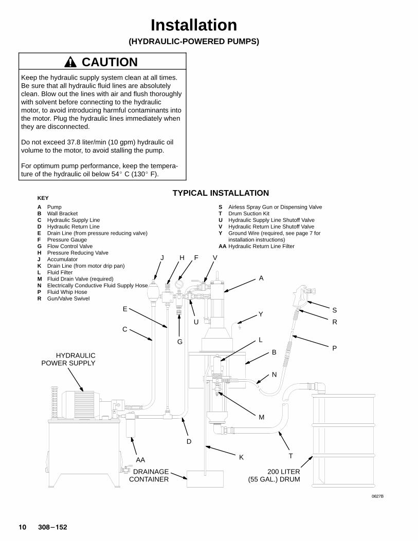
KEY
A PumpB Wall BracketC Hydraulic Supply LineD Hydraulic Return LineE Drain Line (from pressure reducing valve)F Pressure GaugeG Flow Control ValveH Pressure Reducing ValveJ AccumulatorK Drain Line (from motor drip pan)L Fluid FilterM Fluid Drain Valve (required)N Electrically Conductive Fluid Supply HoseP Fluid Whip HoseR Gun/Valve Swivel
S Airless Spray Gun or Dispensing ValveT Drum Suction KitU Hydraulic Supply Line Shutoff ValveV Hydraulic Return Line Shutoff ValveY Ground Wire (required, see page 7 for
installation instructions)AA Hydraulic Return Line Filter
A
B
D
E
F
G
HJ
K
M
N
P
Y
200 LITER (55 GAL.) DRUM
L
R
S
T
UC
V
HYDRAULICPOWER SUPPLY
DRAINAGECONTAINER
AA
TYPICAL INSTALLATION
�� �������
Installation(HYDRAULIC-POWERED PUMPS)
CAUTIONKeep the hydraulic supply system clean at all times.Be sure that all hydraulic fluid lines are absolutelyclean. Blow out the lines with air and flush thoroughlywith solvent before connecting to the hydraulicmotor, to avoid introducing harmful contaminants intothe motor. Plug the hydraulic lines immediately whenthey are disconnected.
Do not exceed 37.8 liter/min (10 gpm) hydraulic oilvolume to the motor, to avoid stalling the pump.
For optimum pump performance, keep the tempera-ture of the hydraulic oil below 54� C (130� F).
������� ��
Installation(HYDRAULIC-POWERED PUMPS)
System Accessories
The Typical Installation on page 10 is only a guidefor selecting and installing system components andaccessories. Contact your Graco distributor for assis-tance in designing a system to suit your particularneeds.
WARNINGA fluid drain valve (M) is required in your system.This accessory helps reduce the risk of seriousinjury, including fluid injection and splashing in theeyes or on the skin, and injury from moving parts ifyou are adjusting or repairing the pump.
The fluid drain valve assists in relieving fluid pres-sure in the displacement pump, hose, and gun.Triggering the gun to relieve pressure may not besufficient. Order Part No. 210–658.
Mounting Accessories
Mount the pump (A) to suit the type of installationplanned. The Typical Installation on page 10 illus-trates a wall-mounted system. Pump dimensions andthe mounting hole layout are shown on pages 40 and41.
Filters
Be sure your hydraulic power supply is equipped with asuction filter to the hydraulic pump and a system returnline filter (AA) of 10 micron size.
Carefully follow the manufacturer’s recommendationson reservoir and filter cleaning, and periodic changesof hydraulic fluid. Use only Graco-approved hydraulicoil. Order Part No. 169–236 for 19 liter (5 gal.) or PartNo. 207–428 for 3.8 liter (1 gal.) power supplies.
Hydraulic Lines
The motor has a 3/4 npt(f) hydraulic oil supply fitting,and a 1” npt(f) hydraulic oil return fitting. Use a mini-mum 13 mm (1/2 in.) ID hydraulic supply line, and aminimum 22 mm (7/8 in.) ID return line.
On the hydraulic supply line (C), install the followingaccessories in the order shown in Fig. 10, using adapt-ers as necessary:
� A shutoff valve (U) isolates the pump for service.
� A fluid pressure gauge (F) to monitor hydraulic oilpressure to the motor and to avoid overpressurizingthe motor or displacement pump, and a pressureand temperature compensated flow controlvalve (G) to prevent the motor from running toofast and possibly damaging itself.
� A pressure reducing valve (H), with a drain line(E) run directly to the hydraulic return line (D).
� An accumulator (J) to reduce the hammeringeffect caused by the motor reversing direction.
On the hydraulic return line (D), install the followingaccessories in the order shown in the Typical Installa-tion on page 10, using adapters as necessary:
� A shutoff valve (V) isolates the pump for service.
� A filter (AA) of 10 micron size.
Hydraulic Motor Drip Pan
The hydraulic motor has a drip pan to collect anyleakage. Connect a 6 mm (1/4 in.) ID drain line (K) tothe barbed fitting on the drip pan, and place the freeend in a container to receive the drainage.
Fluid Supply Hoses
Be sure all fluid supply hoses (N and P) are properlysized and pressure-rated for your system. Use onlyelectrically conductive hoses. Use a whip hose (P) anda swivel (R) between the main fluid hose (N) and thegun/valve (S) to allow for easier gun/valve movement.
Fluid Line Accessories
Install the following accessories in the positions shownin the Typical Installation on page 10, using adaptersas necessary:
� A fluid filter (L) with a 60 mesh (250 micron)stainless steel element, to filter particles from thefluid as it leaves the pump. It includes a fluid drainvalve (M), which is required in your system torelieve fluid pressure in the hose and gun (see theWARNING at left).
� A gun or valve (S) dispenses the fluid. The gunshown in the Typical Installation on page 10 is anairless spray gun for light to medium viscosityfluids.
� A gun swivel (R) allows for easier gun movement.
� A suction kit (T) allows the pump to draw fluidfrom a 200 liter (55 gallon) drum.

�� �������
Notes
������� ��
Operation/Maintenance(All PUMPS)
Pressure Relief Procedure
WARNINGINJECTION HAZARDThe system pressure must be manuallyrelieved to prevent the system fromstarting or spraying accidentally. Fluid
under high pressure can be injected through theskin and cause serious injury. To reduce the risk ofan injury from injection, splashing fluid, or movingparts, follow the Pressure Relief Procedurewhenever you:
� are instructed to relieve the pressure,� stop spraying,� check or service any of the system equipment,� or install or clean the spray tips.
�� Lock the gun trigger safety.
�� Shut off the air or hydraulic supply to the pump.
�� In air-powered systems, close the bleed-type mas-ter air valve (required in your system).
In hydraulic-powered systems, close the hydraulicsupply line valve first, then the return line valve.
�� Unlock the gun trigger safety.
�� Hold a metal part of the gun firmly to the side of agrounded metal pail, and trigger the gun to relievepressure.
�� Lock the gun trigger safety.
� Open the drain valve (required in your system),having a container ready to catch the drainage.
� Leave the drain valve open until you are ready tospray again.
If you suspect that the spray tip or hose is completelyclogged, or that pressure has not been fully relievedafter following the steps above, very slowly loosen thetip guard retaining nut or hose end coupling and relievepressure gradually, then loosen completely. Now clearthe tip or hose.
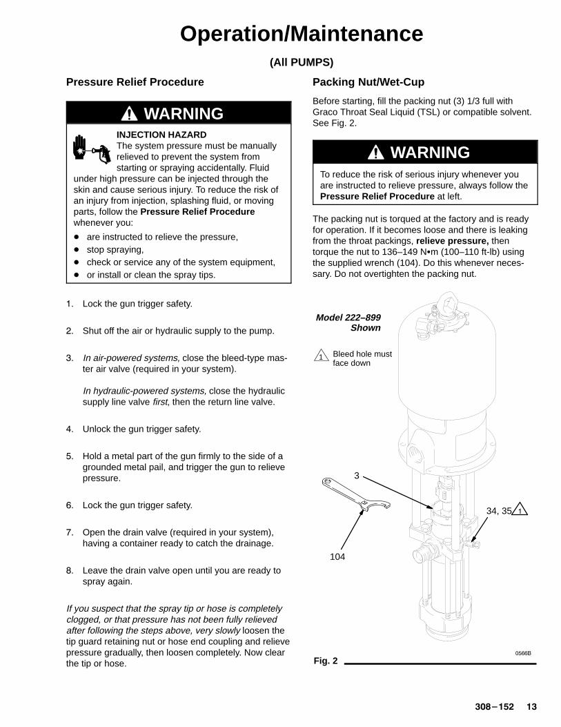
Packing Nut/Wet-Cup
Before starting, fill the packing nut (3) 1/3 full withGraco Throat Seal Liquid (TSL) or compatible solvent.See Fig. 2.
WARNINGTo reduce the risk of serious injury whenever youare instructed to relieve pressure, always follow thePressure Relief Procedure at left.
The packing nut is torqued at the factory and is readyfor operation. If it becomes loose and there is leakingfrom the throat packings, relieve pressure, thentorque the nut to 136–149 N�m (100–110 ft-lb) usingthe supplied wrench (104). Do this whenever neces-sary. Do not overtighten the packing nut.
Fig. 2
Model 222–899Shown
1 Bleed hole must face down
3
34, 35
104
�
�����
�� �������
Operation/Maintenance(AIR-POWERED PUMPS)
Flush the Pump Before First Use
The pump is tested with lightweight oil, which is left into protect the pump parts. If the fluid you are usingmay be contaminated by the oil, flush it out with acompatible solvent. See Flushing on page 17.
Starting and Adjusting the Pump
1. Refer to the Typical Installation on page 8.Connect the suction kit (T) to the pump’s fluid inlet,and place the tube into the fluid supply.
2. Be sure the air regulator (F) is closed. Then openthe pump’s bleed-type master air valve (E). Hold ametal part of the spray gun/dispensing valve firmlyto the side of a grounded metal pail and hold thetrigger open. Now slowly open the air regulatoruntil the pump starts.
3. Cycle the pump slowly until all air is pushed outand the pump and hoses are fully primed. Releasethe gun/valve trigger and lock the trigger safety.The pump should stall against pressure when thetrigger is released.
WARNINGINJECTION HAZARDTo reduce the risk of fluid injection, do not use yourhand or fingers to cover the bleed hole on the un-derside of the bleeder valve body (34) when prim-ing the pump. Use a crescent wrench to open andclose the bleeder plug (35). Keep your hands awayfrom the bleed hole.
4. If the pump fails to prime properly, open the bleed-er valve plug (35) slightly. Use the bleed hole onthe underside of the valve body (34) as a primingvalve until the fluid appears at the hole. See Fig. 2.Close the plug (35).
NOTE: When changing fluid containers with the hoseand gun already primed, open the bleeder valve plug(35) to help prime the pump and vent air before itenters the hose. Close the plug when all air is elimi-nated.
CAUTIONDo not allow the pump to run dry. It will quicklyaccelerate to a high speed, causing damage. If youpump is running too fast, stop it immediately andcheck the fluid supply. If the container is empty andair has been pumped into the lines, refill the contain-er and prime the pump and the lines, or flush andleave it filled with a compatible solvent. Eliminate allair from the fluid system.
5. With the pump and lines primed, and with ade-quate air pressure and volume supplied, the pumpwill start and stop as the gun/valve is opened andclosed. In a circulating system, the pump willspeed up or slow down on demand, until the airsupply is shut off.
6. Use the air regulator to control the pump speedand the fluid pressure. Always use the lowest airpressure necessary to get the desired results.Higher pressures cause premature tip/nozzle andpump wear.
WARNINGCOMPONENT RUPTURE HAZARDTo reduce the risk of overpressurizingyour system, which could cause compo-nent rupture and serious injury, never
exceed the specified Maximum Incoming Air Pres-sure to the pump (see the Technical Data on page32–37).
������� ��
Operation/Maintenance(AIR-POWERED PUMPS)
Shutdown and Care of the Pump
WARNINGTo reduce the risk of serious injury whenever youare instructed to relieve pressure, always follow thePressure Relief Procedure on page 13.
For overnight shutdown, stop the pump at the bottomof its stroke to prevent fluid from drying on the ex-posed displacement rod and damaging the throatpackings. Relieve the pressure.
Always flush the pump before the fluid dries on thedisplacement rod. See Flushing below.
Flushing
WARNINGFIRE AND EXPLOSION HAZARDBefore flushing, read the section FIREAND EXPLOSION HAZARD on page5. Be sure the entire system and flush-ing pails are properly grounded. Refer toGrounding on page 7.
Flush with a fluid that is compatible with the fluid youare pumping and with the wetted parts in your system.Check with your fluid manufacturer or supplier for rec-ommended flushing fluids and flushing frequency. Al-ways flush the pump before fluid dries on the displace-ment rod.
WARNINGTo reduce the risk of serious injury whenever youare instructed to relieve pressure, always follow thePressure Relief Procedure on page 13.
�� Relieve the pressure.
�� Remove the spray tip from the gun.
�� Hold a metal part of the gun firmly to the side of agrounded metal pail.
�� Start the pump. Always use the lowest possiblefluid pressure when flushing.
�� Trigger the gun.
�� Flush the system until clear solvent flows from thegun.
�� Relieve the pressure.
�� �������
Operation/Maintenance(HYDRAULIC-POWERED PUMPS)
Flush the Pump Before First Use
The pump is tested with lightweight oil, which is left into protect the pump parts. If the fluid you are usingmay be contaminated by the oil, flush it out with acompatible solvent. See Flushing on page 17.
Starting and Adjusting the Pump
�� Refer to the Typical Installation on page 10. Con-nect the suction kit (T) to the pump’s fluid inlet,and place the tube into the fluid supply.
�� Check the hydraulic fluid level before each use,and add fluid as necessary.
�� Make certain that the supply line shutoff valve (U)and the return line shutoff valve (V) are closed.
�� Start the hydraulic power supply.
�� Hold a metal part of the gun (S) firmly to the sideof a grounded metal pail and hold the trigger open.
�� Open the return line shutoff valve (V) first, thenslowly open the supply line shutoff valve (U).
� Cycle the pump slowly until all air is pushed outand the pump and hoses are fully primed.
� Release the gun trigger and lock the trigger safety.The pump should stall against pressure.
WARNINGINJECTION HAZARDTo reduce the risk of fluid injection, do not use yourhand or fingers to cover the bleed hole on the un-derside of the bleeder valve body (34) when prim-ing the pump. Use a crescent wrench to open andclose the bleeder plug (35). Keep your hands awayfrom the bleed hole.
9. If the pump fails to prime properly, open the bleed-er valve plug (35) slightly. Use the bleed hole onthe underside of the valve body (34) as a primingvalve until the fluid appears at the hole. See Fig. 2.Close the plug (35).
NOTE: When changing fluid containers with the hoseand gun already primed, open the bleeder valve plug(35) to help prime the pump and vent air before itenters the hose. Close the plug when all air is elimi-nated.
CAUTIONDo not allow the pump to run dry. It will quicklyaccelerate to a high speed, causing damage. If youpump is running too fast, stop it immediately andcheck the fluid supply. If the container is empty andair has been pumped into the lines, refill the contain-er and prime the pump and the lines, or flush andleave it filled with a compatible solvent. Eliminate allair from the fluid system.
��� With the pump and lines primed, and with ade-quate hydraulic volume supplied, the pump willstart and stop as you open and close the gun. In acirculating system, the pump will speed up or slowdown on demand, until the hydraulic power supplyis shut off.
��� Use the fluid pressure gauge (F) and flow controlvalve (G) to control the pump speed and the fluidoutlet pressure. Always use the lowest hydraulicflow and pressure necessary to get the desiredresults. Higher pressures cause premature tip/noz-zle and pump wear.
WARNINGCOMPONENT RUPTURE HAZARDTo reduce the risk of overpressurizingyour system, which could cause compo-nent rupture and serious injury, never
exceed 10.5 MPa, 105 bar (1500 psi) MaximumHydraulic Input Pressure to the pump, 14.0 MPa,140 bar (2000 psi) Maximum Fluid Working Pres-sure (see the Technical Data on pages 38–39).
To prevent overpressurizing the hydraulic motor orits seals, always shut off the supply line valve (U)first, then shut off the return line valve (V).
CAUTIONDo not allow the hydraulic oil temperature to exceed54�C (130�F). The pump seals will wear faster andleakage may occur if the pump is operated at higheroil temperatures.
������� ��
Operation/Maintenance(HYDRAULIC-POWERED PUMPS)
Shutdown and Care of the Pump
WARNINGTo reduce the risk of serious injury whenever youare instructed to relieve pressure, always follow thePressure Relief Procedure on page 13.
For overnight shutdown, stop the pump at the bottomof its stroke to prevent fluid from drying on the ex-posed displacement rod and damaging the throatpackings. Relieve the pressure.
Always flush the pump before the fluid dries on thedisplacement rod. See Flushing below.
Flushing
WARNINGFIRE AND EXPLOSION HAZARDBefore flushing, read the section FIREAND EXPLOSION HAZARD on page5. Be sure the entire system and flush-ing pails are properly grounded. Refer toGrounding on page 7.
Flush with a fluid that is compatible with the fluid youare pumping and with the wetted parts in your system.Check with your fluid manufacturer or supplier for rec-ommended flushing fluids and flushing frequency. Al-ways flush the pump before fluid dries on the displace-ment rod.
WARNINGTo reduce the risk of serious injury whenever youare instructed to relieve pressure, always follow thePressure Relief Procedure on page 13.
�� Relieve the pressure.
�� Remove the spray tip from the gun.
�� Hold a metal part of the gun firmly to the side of agrounded metal pail.
�� Start the pump. Always use the lowest possiblefluid pressure when flushing.
�� Trigger the gun.
�� Flush the system until clear solvent flows from thegun.
�� Relieve the pressure.

�� �������
Notes
������� ��
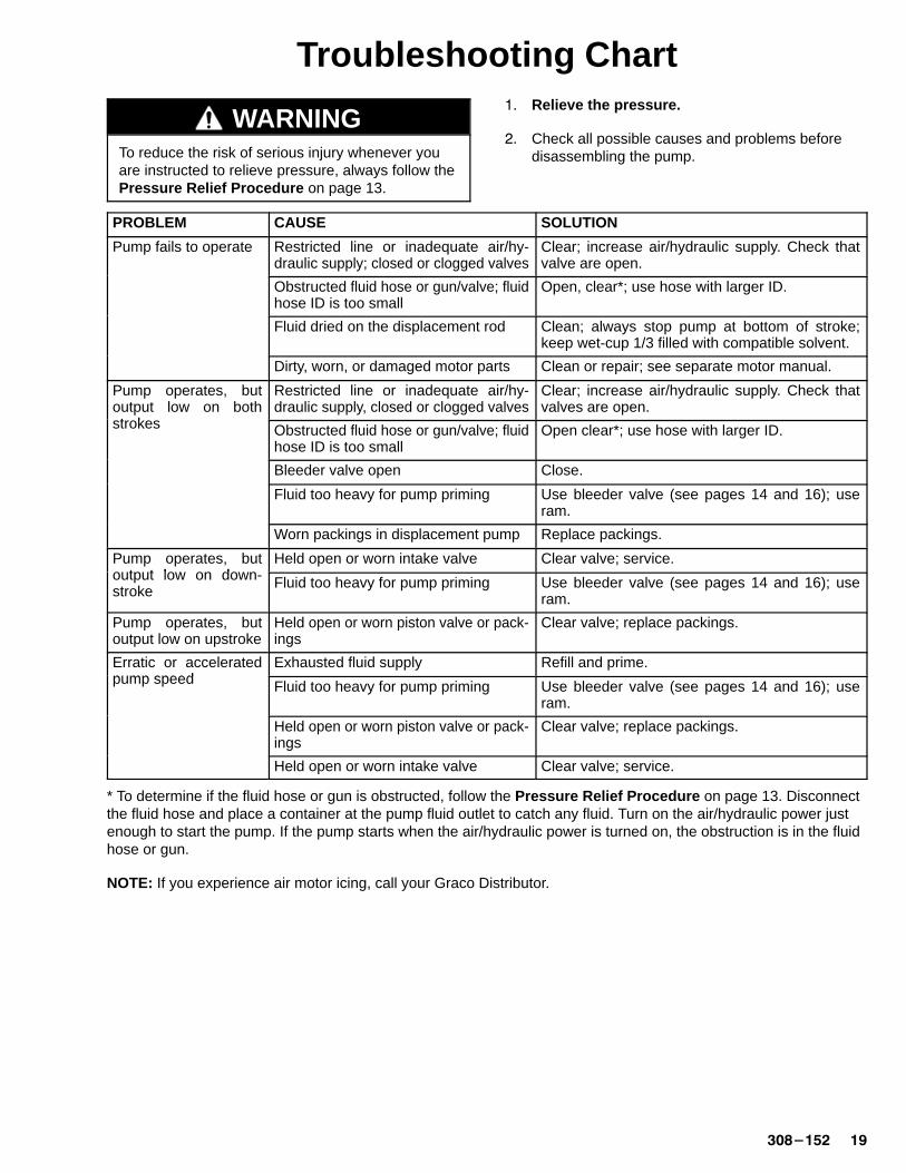
Troubleshooting Chart
WARNINGTo reduce the risk of serious injury whenever youare instructed to relieve pressure, always follow thePressure Relief Procedure on page 13.
�� Relieve the pressure.
�� Check all possible causes and problems beforedisassembling the pump.
PROBLEM CAUSE SOLUTION
Pump fails to operate Restricted line or inadequate air/hy-draulic supply; closed or clogged valves
Clear; increase air/hydraulic supply. Check thatvalve are open.
Obstructed fluid hose or gun/valve; fluidhose ID is too small
Open, clear*; use hose with larger ID.
Fluid dried on the displacement rod Clean; always stop pump at bottom of stroke;keep wet-cup 1/3 filled with compatible solvent.
Dirty, worn, or damaged motor parts Clean or repair; see separate motor manual.
Pump operates, butoutput low on bothstrokes
Restricted line or inadequate air/hy-draulic supply, closed or clogged valves
Clear; increase air/hydraulic supply. Check thatvalves are open.p
strokes Obstructed fluid hose or gun/valve; fluidhose ID is too small
Open clear*; use hose with larger ID.
Bleeder valve open Close.
Fluid too heavy for pump priming Use bleeder valve (see pages 14 and 16); useram.
Worn packings in displacement pump Replace packings.
Pump operates, butoutput low on down
Held open or worn intake valve Clear valve; service.p poutput low on down-stroke
Fluid too heavy for pump priming Use bleeder valve (see pages 14 and 16); useram.
Pump operates, butoutput low on upstroke
Held open or worn piston valve or pack-ings
Clear valve; replace packings.
Erratic or acceleratedpump speed
Exhausted fluid supply Refill and prime.pump speed Fluid too heavy for pump priming Use bleeder valve (see pages 14 and 16); use
ram.
Held open or worn piston valve or pack-ings
Clear valve; replace packings.
Held open or worn intake valve Clear valve; service.
* To determine if the fluid hose or gun is obstructed, follow the Pressure Relief Procedure on page 13. Disconnectthe fluid hose and place a container at the pump fluid outlet to catch any fluid. Turn on the air/hydraulic power justenough to start the pump. If the pump starts when the air/hydraulic power is turned on, the obstruction is in the fluidhose or gun.
NOTE: If you experience air motor icing, call your Graco Distributor.
�� �������
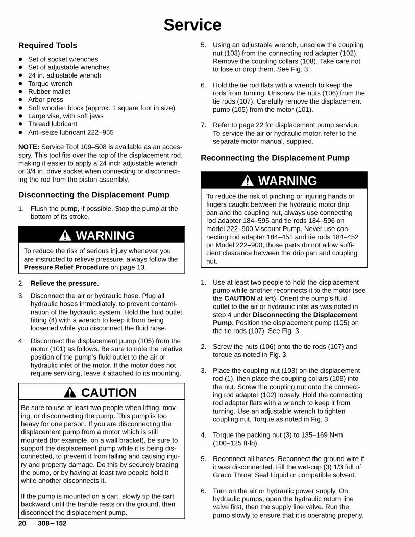
ServiceRequired Tools
� Set of socket wrenches� Set of adjustable wrenches� 24 in. adjustable wrench� Torque wrench� Rubber mallet� Arbor press� Soft wooden block (approx. 1 square foot in size)� Large vise, with soft jaws� Thread lubricant� Anti-seize lubricant 222–955
NOTE: Service Tool 109–508 is available as an acces-sory. This tool fits over the top of the displacement rod,making it easier to apply a 24 inch adjustable wrenchor 3/4 in. drive socket when connecting or disconnect-ing the rod from the piston assembly.
Disconnecting the Displacement Pump
1. Flush the pump, if possible. Stop the pump at thebottom of its stroke.
WARNINGTo reduce the risk of serious injury whenever youare instructed to relieve pressure, always follow thePressure Relief Procedure on page 13.
2. Relieve the pressure.
3. Disconnect the air or hydraulic hose. Plug allhydraulic hoses immediately, to prevent contami-nation of the hydraulic system. Hold the fluid outletfitting (4) with a wrench to keep it from beingloosened while you disconnect the fluid hose.
4. Disconnect the displacement pump (105) from themotor (101) as follows. Be sure to note the relativeposition of the pump’s fluid outlet to the air orhydraulic inlet of the motor. If the motor does notrequire servicing, leave it attached to its mounting.
CAUTIONBe sure to use at least two people when lifting, mov-ing, or disconnecting the pump. This pump is tooheavy for one person. If you are disconnecting thedisplacement pump from a motor which is stillmounted (for example, on a wall bracket), be sure tosupport the displacement pump while it is being dis-connected, to prevent it from falling and causing inju-ry and property damage. Do this by securely bracingthe pump, or by having at least two people hold itwhile another disconnects it.
If the pump is mounted on a cart, slowly tip the cartbackward until the handle rests on the ground, thendisconnect the displacement pump.
5. Using an adjustable wrench, unscrew the couplingnut (103) from the connecting rod adapter (102).Remove the coupling collars (108). Take care notto lose or drop them. See Fig. 3.
6. Hold the tie rod flats with a wrench to keep therods from turning. Unscrew the nuts (106) from thetie rods (107). Carefully remove the displacementpump (105) from the motor (101).
7. Refer to page 22 for displacement pump service.To service the air or hydraulic motor, refer to theseparate motor manual, supplied.
Reconnecting the Displacement Pump
WARNINGTo reduce the risk of pinching or injuring hands orfingers caught between the hydraulic motor drippan and the coupling nut, always use connectingrod adapter 184–595 and tie rods 184–596 onmodel 222–900 Viscount Pump. Never use con-necting rod adapter 184–451 and tie rods 184–452on Model 222–900; those parts do not allow suffi-cient clearance between the drip pan and couplingnut.
1. Use at least two people to hold the displacementpump while another reconnects it to the motor (seethe CAUTION at left). Orient the pump’s fluidoutlet to the air or hydraulic inlet as was noted instep 4 under Disconnecting the DisplacementPump . Position the displacement pump (105) onthe tie rods (107). See Fig. 3.
2. Screw the nuts (106) onto the tie rods (107) andtorque as noted in Fig. 3.
3. Place the coupling nut (103) on the displacementrod (1), then place the coupling collars (108) intothe nut. Screw the coupling nut onto the connect-ing rod adapter (102) loosely. Hold the connectingrod adapter flats with a wrench to keep it fromturning. Use an adjustable wrench to tightencoupling nut. Torque as noted in Fig. 3.
4. Torque the packing nut (3) to 135–169 N�m(100–125 ft-lb).
5. Reconnect all hoses. Reconnect the ground wire ifit was disconnected. Fill the wet-cup (3) 1/3 full ofGraco Throat Seal Liquid or compatible solvent.
6. Turn on the air or hydraulic power supply. Onhydraulic pumps, open the hydraulic return linevalve first, then the supply line valve. Run thepump slowly to ensure that it is operating properly.
������� ��
Service
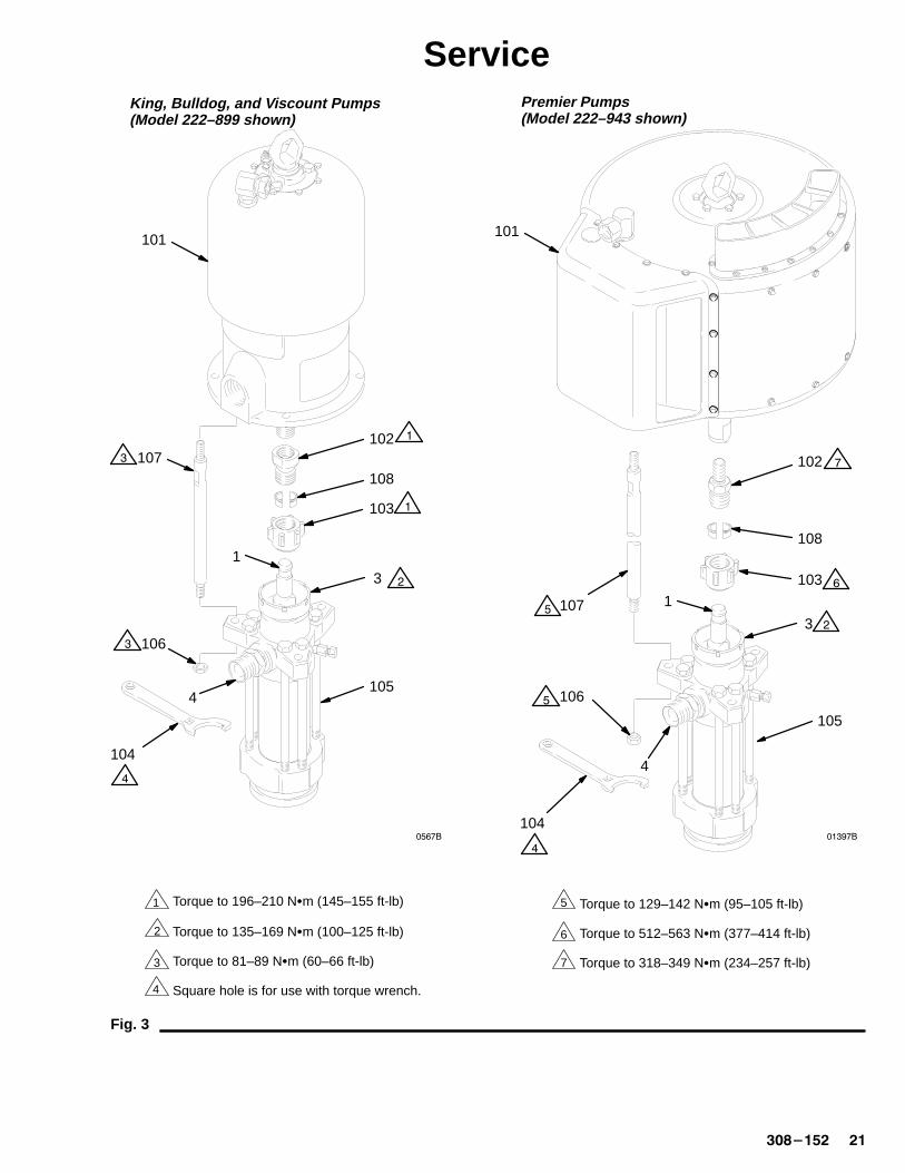
Fig. 3
King, Bulldog, and V iscount Pumps(Model 222–899 shown)
1 Torque to 196–210 N�m (145–155 ft-lb)
Premier Pumps(Model 222–943 shown)
4
Torque to 135–169 N�m (100–125 ft-lb)
Torque to 81–89 N�m (60–66 ft-lb)
Square hole is for use with torque wrench.
Torque to 129–142 N�m (95–105 ft-lb)
Torque to 512–563 N�m (377–414 ft-lb)
Torque to 318–349 N�m (234–257 ft-lb)
2
3
5
6
7
3
108
101
106
1
����
1054
104
107102
103
�
�
�
�
�
�
105
104
106
108
102
107
103
����
4
3 �
�
�
�
�
�
101
1
�� �������
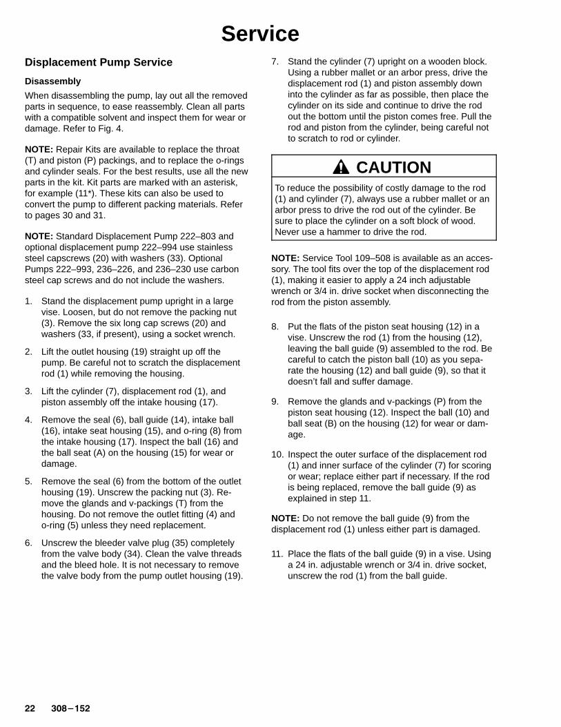
ServiceDisplacement Pump Service
Disassembly
When disassembling the pump, lay out all the removedparts in sequence, to ease reassembly. Clean all partswith a compatible solvent and inspect them for wear ordamage. Refer to Fig. 4.
NOTE: Repair Kits are available to replace the throat(T) and piston (P) packings, and to replace the o-ringsand cylinder seals. For the best results, use all the newparts in the kit. Kit parts are marked with an asterisk,for example (11*). These kits can also be used toconvert the pump to different packing materials. Referto pages 30 and 31.
NOTE: Standard Displacement Pump 222–803 andoptional displacement pump 222–994 use stainlesssteel capscrews (20) with washers (33). OptionalPumps 222–993, 236–226, and 236–230 use carbonsteel cap screws and do not include the washers.
1. Stand the displacement pump upright in a largevise. Loosen, but do not remove the packing nut(3). Remove the six long cap screws (20) andwashers (33, if present), using a socket wrench.
2. Lift the outlet housing (19) straight up off thepump. Be careful not to scratch the displacementrod (1) while removing the housing.
3. Lift the cylinder (7), displacement rod (1), andpiston assembly off the intake housing (17).
4. Remove the seal (6), ball guide (14), intake ball(16), intake seat housing (15), and o-ring (8) fromthe intake housing (17). Inspect the ball (16) andthe ball seat (A) on the housing (15) for wear ordamage.
5. Remove the seal (6) from the bottom of the outlethousing (19). Unscrew the packing nut (3). Re-move the glands and v-packings (T) from thehousing. Do not remove the outlet fitting (4) ando-ring (5) unless they need replacement.
6. Unscrew the bleeder valve plug (35) completelyfrom the valve body (34). Clean the valve threadsand the bleed hole. It is not necessary to removethe valve body from the pump outlet housing (19).
7. Stand the cylinder (7) upright on a wooden block.Using a rubber mallet or an arbor press, drive thedisplacement rod (1) and piston assembly downinto the cylinder as far as possible, then place thecylinder on its side and continue to drive the rodout the bottom until the piston comes free. Pull therod and piston from the cylinder, being careful notto scratch to rod or cylinder.
CAUTIONTo reduce the possibility of costly damage to the rod(1) and cylinder (7), always use a rubber mallet or anarbor press to drive the rod out of the cylinder. Besure to place the cylinder on a soft block of wood.Never use a hammer to drive the rod.
NOTE: Service Tool 109–508 is available as an acces-sory. The tool fits over the top of the displacement rod(1), making it easier to apply a 24 inch adjustablewrench or 3/4 in. drive socket when disconnecting therod from the piston assembly.
8. Put the flats of the piston seat housing (12) in avise. Unscrew the rod (1) from the housing (12),leaving the ball guide (9) assembled to the rod. Becareful to catch the piston ball (10) as you sepa-rate the housing (12) and ball guide (9), so that itdoesn’t fall and suffer damage.
9. Remove the glands and v-packings (P) from thepiston seat housing (12). Inspect the ball (10) andball seat (B) on the housing (12) for wear or dam-age.
10. Inspect the outer surface of the displacement rod(1) and inner surface of the cylinder (7) for scoringor wear; replace either part if necessary. If the rodis being replaced, remove the ball guide (9) asexplained in step 11.
NOTE: Do not remove the ball guide (9) from thedisplacement rod (1) unless either part is damaged.
11. Place the flats of the ball guide (9) in a vise. Usinga 24 in. adjustable wrench or 3/4 in. drive socket,unscrew the rod (1) from the ball guide.
������� ��
Service
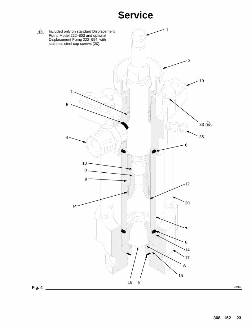
Fig. 4
Included only on standard Displacement Pump Model 222–803 and optionalDisplacement Pump 222–994, withstainless steel cap screws (20).
101
9
10
7
17
15
16
14
19
35
5
4
20
3
12
6
6
A
B
T
P
8
33 ��
�����
�� �������
ServiceReassembly
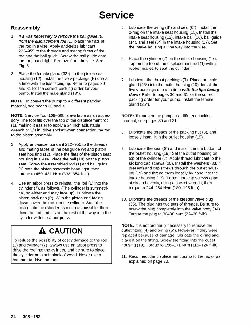
1. If it was necessary to remove the ball guide (9)from the displacement rod (1), place the flats ofthe rod in a vise. Apply anti-seize lubricant222–955 to the threads and mating faces of therod and the ball guide. Screw the ball guide ontothe rod, hand tight. Remove from the vise. SeeFig. 5.
2. Place the female gland (32*) on the piston seathousing (12). Install the five v-packings (P) one ata time with the lips facing up. Refer to pages 30and 31 for the correct packing order for yourpump. Install the male gland (13*).
NOTE: To convert the pump to a different packingmaterial, see pages 30 and 31.
NOTE: Service Tool 109–508 is available as an acces-sory. The tool fits over the top of the displacement rod(1), making it easier to apply a 24 inch adjustablewrench or 3/4 in. drive socket when connecting the rodto the piston assembly.
3. Apply anti-seize lubricant 222–955 to the threadsand mating faces of the ball guide (9) and pistonseat housing (12). Place the flats of the piston seathousing in a vise. Place the ball (10) on the pistonseat. Screw the assembled rod (1) and ball guide(9) onto the piston assembly hand tight, thentorque to 459–481 N�m (338–354 ft-lb).
4. Use an arbor press to reinstall the rod (1) into thecylinder (7), as follows. (The cylinder is symmetri-cal, so either end may face up). Lubricate thepiston packings (P). With the piston end facingdown, lower the rod into the cylinder. Start thepiston into the cylinder as much as possible. thendrive the rod and piston the rest of the way into thecylinder with the arbor press.
CAUTIONTo reduce the possibility of costly damage to the rod(1) and cylinder (7), always use an arbor press todrive the rod into the cylinder, and be sure to placethe cylinder on a soft block of wood. Never use ahammer to drive the rod.
5. Lubricate the o-ring (8*) and seal (6*). Install theo-ring on the intake seat housing (15). Install theintake seat housing (15), intake ball (16), ball guide(14), and seal (6*) in the intake housing (17). Setthe intake housing all the way into the vise.
6. Place the cylinder (7) on the intake housing (17).Tap on the top of the displacement rod (1) with arubber mallet, to seat the cylinder.
7. Lubricate the throat packings (T). Place the malegland (28*) into the outlet housing (19). Install thefive v-packings one at a time with the lips facingdown . Refer to pages 30 and 31 for the correctpacking order for your pump. Install the femalegland (25*).
NOTE: To convert the pump to a different packingmaterial, see pages 30 and 31.
8. Lubricate the threads of the packing nut (3), andloosely install it in the outlet housing (19).
9. Lubricate the seal (6*) and install it in the bottom ofthe outlet housing (19). Set the outlet housing ontop of the cylinder (7). Apply thread lubricant to thesix long cap screws (20). Install the washers (33, ifpresent) and cap screws through the outlet hous-ing (19) and thread them loosely by hand into theintake housing (17). Tighten the cap screws oppo-sitely and evenly, using a socket wrench, thentorque to 244–264 N�m (180–195 ft-lb).
10. Lubricate the threads of the bleeder valve plug(35). The plug has two sets of threads. Be sure toscrew the plug completely into the valve body (34).Torque the plug to 30–38 N�m (22–28 ft-lb).
NOTE: It is not ordinarily necessary to remove theoutlet fitting (4) and o-ring (5*). However, if they werereplaced because of damage, lubricate the o-ring andplace it on the fitting. Screw the fitting into the outlethousing (19). Torque to 156–171 N�m (115–126 ft-lb).
11. Reconnect the displacement pump to the motor asexplained on page 20.
������� ��
Service
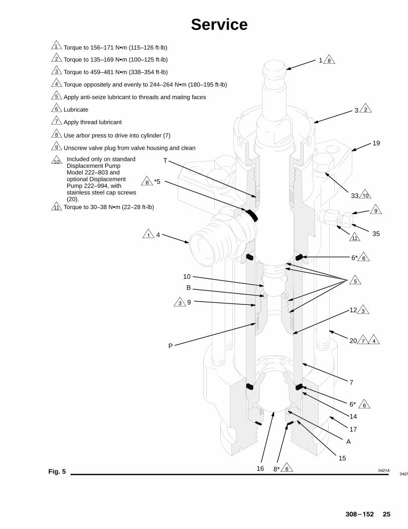
Fig. 5
1
2
3
4
5
6
7
8
9
10
Torque to 156–171 N�m (115–126 ft-lb)
Torque to 135–169 N�m (100–125 ft-lb)
Torque to 459–481 N�m (338–354 ft-lb)
Torque oppositely and evenly to 244–264 N�m (180–195 ft-lb)
Apply anti-seize lubricant to threads and mating faces
Lubricate
Apply thread lubricant
Use arbor press to drive into cylinder (7)
Unscrew valve plug from valve housing and clean
Included only on standard Displacement PumpModel 222–803 andoptional DisplacementPump 222–994, withstainless steel cap screws(20).
11 Torque to 30–38 N�m (22–28 ft-lb)
����
1
9
10
7
17
15
16
14
19
35
*5
4
20
3
12
6*
6*
A
B
�
�
�
�
�
� �
�
�
�
�
T
P
8*
��33
�����
11
�� �������
Parts
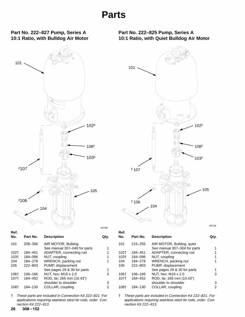
Part No. 222–827 Pump, Series A10:1 Ratio, with Bulldog Air Motor
Ref.No. Part No. Description Qty.
101 208–356 AIR MOTOR, BulldogSee manual 307–049 for parts 1
102� 184–451 ADAPTER, connecting rod 1103� 184–096 NUT, coupling 1104 184–278 WRENCH, packing nut 1105 222–803 PUMP, displacement
See pages 29 & 30 for parts 1106� 106–166 NUT, hex; M16 x 2.0 3107� 184–452 ROD, tie; 265 mm (10.43”)
shoulder to shoulder 3108� 184–130 COLLAR, coupling 2
� These parts are included in Connection Kit 222–821. Forapplications requiring stainless steel tie rods, order Con-nection Kit 222–913.
Part No. 222–825 Pump, Series A10:1 Ratio, with Quiet Bulldog Air Motor
Ref.No. Part No. Description Qty.
101 215–255 AIR MOTOR, Bulldog, quietSee manual 307–304 for parts 1
102� 184–451 ADAPTER, connecting rod 1103� 184–096 NUT, coupling 1104 184–278 WRENCH, packing nut 1105 222–803 PUMP, displacement
See pages 29 & 30 for parts 1106� 106–166 NUT, hex; M16 x 2.0 3107� 184–452 ROD, tie; 265 mm (10.43”)
shoulder to shoulder 3108� 184–130 COLLAR, coupling 2
� These parts are included in Connection Kit 222–821. Forapplications requiring stainless steel tie rods, order Con-nection Kit 222–913.
0570B
101
105
104
†106
108†
102†
†107
103†
0571B
101
105
104†106
108†
102†
†107
103†
������� ��
Parts
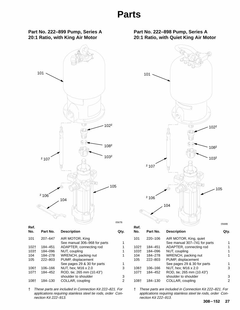
Part No. 222–899 Pump, Series A20:1 Ratio, with King Air Motor
Ref.No. Part No. Description Qty.
101 207–647 AIR MOTOR, KingSee manual 306–968 for parts 1
102� 184–451 ADAPTER, connecting rod 1103� 184–096 NUT, coupling 1104 184–278 WRENCH, packing nut 1105 222–803 PUMP, displacement
See pages 29 & 30 for parts 1106� 106–166 NUT, hex; M16 x 2.0 3107� 184–452 ROD, tie; 265 mm (10.43”)
shoulder to shoulder 3108� 184–130 COLLAR, coupling 2
� These parts are included in Connection Kit 222–821. Forapplications requiring stainless steel tie rods, order Con-nection Kit 222–913.
Part No. 222–898 Pump, Series A20:1 Ratio, with Quiet King Air Motor
Ref.No. Part No. Description Qty.
101 220–106 AIR MOTOR, King, quietSee manual 307–741 for parts 1
102� 184–451 ADAPTER, connecting rod 1103� 184–096 NUT, coupling 1104 184–278 WRENCH, packing nut 1105 222–803 PUMP, displacement
See pages 29 & 30 for parts 1106� 106–166 NUT, hex; M16 x 2.0 3107� 184–452 ROD, tie; 265 mm (10.43”)
shoulder to shoulder 3108� 184–130 COLLAR, coupling 2
� These parts are included in Connection Kit 222–821. Forapplications requiring stainless steel tie rods, order Con-nection Kit 222–913.
101
†106
105
108†
104
102†
†107 103†
0567B0568B
101
105
104
†106
108†
102†
†107
103†
�� �������
Parts
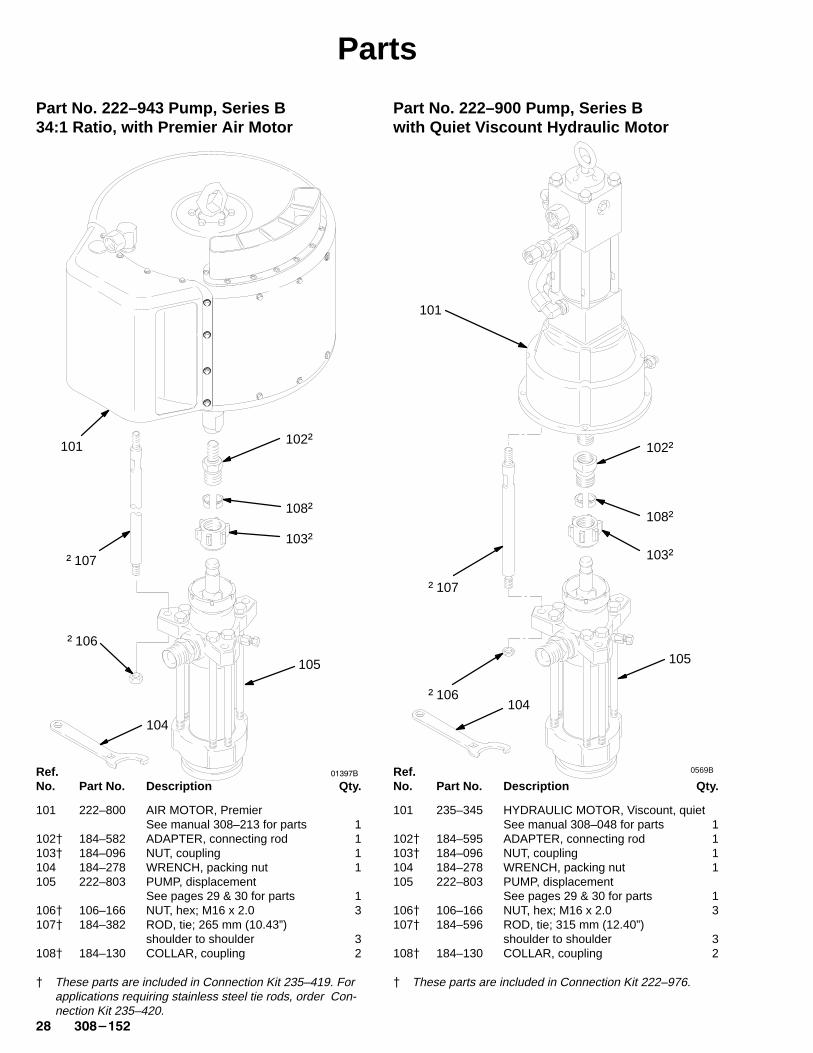
Part No. 222–943 Pump, Series B34:1 Ratio, with Premier Air Motor
Ref.No. Part No. Description Qty.
101 222–800 AIR MOTOR, PremierSee manual 308–213 for parts 1
102� 184–582 ADAPTER, connecting rod 1103� 184–096 NUT, coupling 1104 184–278 WRENCH, packing nut 1105 222–803 PUMP, displacement
See pages 29 & 30 for parts 1106� 106–166 NUT, hex; M16 x 2.0 3107� 184–382 ROD, tie; 265 mm (10.43”)
shoulder to shoulder 3108� 184–130 COLLAR, coupling 2
� These parts are included in Connection Kit 235–419. Forapplications requiring stainless steel tie rods, order Con-nection Kit 235–420.
Part No. 222–900 Pump, Series Bwith Quiet Viscount Hydraulic Motor
Ref.No. Part No. Description Qty.
101 235–345 HYDRAULIC MOTOR, Viscount, quietSee manual 308–048 for parts 1
102� 184–595 ADAPTER, connecting rod 1103� 184–096 NUT, coupling 1104 184–278 WRENCH, packing nut 1105 222–803 PUMP, displacement
See pages 29 & 30 for parts 1106� 106–166 NUT, hex; M16 x 2.0 3107� 184–596 ROD, tie; 315 mm (12.40”)
shoulder to shoulder 3108� 184–130 COLLAR, coupling 2
� These parts are included in Connection Kit 222–976.
101
105
104
†106
108†
102†
†107
103†
������0569B
101
105
104†106
108†
102†
†107
103†

�����
9
1
8*
19
17
16‡
15
14
10‡
7
6*
6* *5
4
34
3
12
Piston Packings(see pages30 and 31)
Throat Packings(see pages30 and 31)
20, 33(see pages 30 and 31)
35
������� ��
Displacement Pump PartsNOTE: The parts listed on this page are common to alldisplacement pumps covered in this manual. The pumps usedifferent packing configurations. Standard Model 222–803and optional Model 222–994 use stainless steel cap screwswith washers. Models 222–993, 236–226, and 236–230 usecarbon steel cap screws without a washer. Refer to pages 30and 31 for the different pump configurations available.
* These parts are included in Packing Repair Kit 222–875,which may be purchased separately for standard Dis-placement Pump 222–803. They are also included in theoptional packing conversion kits listed on pages 30 and31.
‡ Keep these spare parts on hand to reduce down time.
Ref PartNo. No. Description Qty
1 184–002 ROD, displacement; stainless steel 13 184–388 PACKING NUT/WET-CUP;
Stainless steel 14 184–387 FITTING, OUTLET; 1–1/2” npt(m) x
M42 x 2.0; stainless steel 15* 109–213 O-RING; Teflon� 16* 184–072 SEAL; Delrin� 27 184–003 CYLINDER, stainless steel 18* 102–857 O-RING; Teflon� 19 184–297 GUIDE, ball, piston; stainless steel 110‡ 109–220 BALL, piston; stainless steel;
1.5” (38.1 mm) dia. 112 222–802 HOUSING, seat, piston valve;
stainless steel w/tungsten carbide seat 114 184–282 GUIDE, ball, intake; stainless steel 115 222–838 HOUSING, seat, intake valve;
stainless steel w/tungsten carbide seat 116‡ 110–294 BALL, intake; stainless steel;
2” (50.8 mm) dia. 117 184–390 HOUSING, intake; stainless steel 119 222–921 HOUSING, outlet; stainless steel 134 184–392 HOUSING, valve; 3/8–18 npt x
1/2 –20 unf-2a 135 190–293 PLUG, valve; 1/2–30 unf-2a 1
�� �������
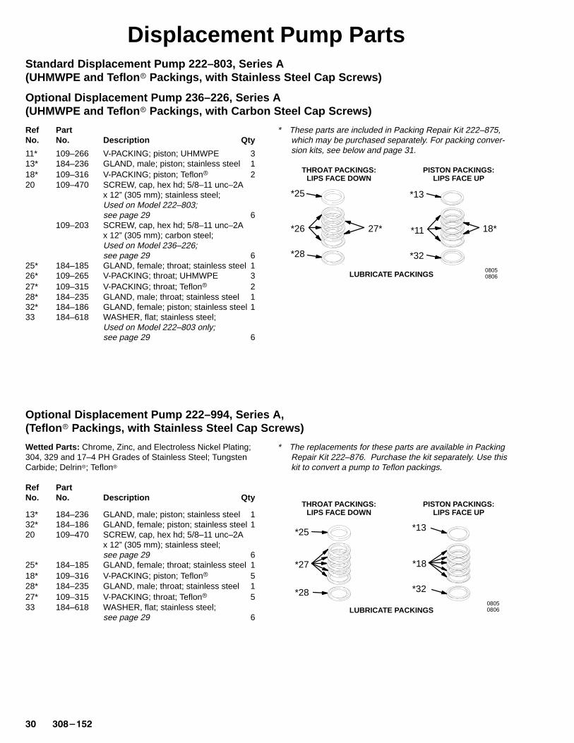
Displacement Pump PartsStandard Displacement Pump 222–803, Series A (UHMWPE and Teflon � Packings, with Stainless Steel Cap Screws)
Optional Displacement Pump 236–226, Series A (UHMWPE and Teflon � Packings, with Carbon Steel Cap Screws)
Ref PartNo. No. Description Qty
11* 109–266 V-PACKING; piston; UHMWPE 313* 184–236 GLAND, male; piston; stainless steel 118* 109–316 V-PACKING; piston; Teflon� 220 109–470 SCREW, cap, hex hd; 5/8–11 unc–2A
x 12” (305 mm); stainless steel;Used on Model 222–803; see page 29 6
109–203 SCREW, cap, hex hd; 5/8–11 unc–2Ax 12” (305 mm); carbon steel;Used on Model 236–226; see page 29 6
25* 184–185 GLAND, female; throat; stainless steel 126* 109–265 V-PACKING; throat; UHMWPE 327* 109–315 V-PACKING; throat; Teflon� 228* 184–235 GLAND, male; throat; stainless steel 132* 184–186 GLAND, female; piston; stainless steel 133 184–618 WASHER, flat; stainless steel;
Used on Model 222–803 only; see page 29 6
* These parts are included in Packing Repair Kit 222–875,which may be purchased separately. For packing conver-sion kits, see below and page 31.
THROAT PACKINGS:LIPS FACE DOWN
PISTON PACKINGS:LIPS FACE UP
08050806LUBRICATE PACKINGS
*11
*32
18*
*25
*26 27*
*28
*13
Optional Displacement Pump 222–994, Series A,(Teflon � Packings, with Stainless Steel Cap Screws)
Wetted Parts: Chrome, Zinc, and Electroless Nickel Plating;304, 329 and 17–4 PH Grades of Stainless Steel; TungstenCarbide; Delrin�; Teflon�
Ref PartNo. No. Description Qty
13* 184–236 GLAND, male; piston; stainless steel 132* 184–186 GLAND, female; piston; stainless steel 120 109–470 SCREW, cap, hex hd; 5/8–11 unc–2A
x 12” (305 mm); stainless steel;see page 29 6
25* 184–185 GLAND, female; throat; stainless steel 118* 109–316 V-PACKING; piston; Teflon� 528* 184–235 GLAND, male; throat; stainless steel 127* 109–315 V-PACKING; throat; Teflon� 533 184–618 WASHER, flat; stainless steel;
see page 29 6
* The replacements for these parts are available in PackingRepair Kit 222–876. Purchase the kit separately. Use thiskit to convert a pump to Teflon packings.
THROAT PACKINGS:LIPS FACE DOWN
PISTON PACKINGS:LIPS FACE UP
08050806
*18
*32
*25
*27
*28
*13
LUBRICATE PACKINGS
������� ��
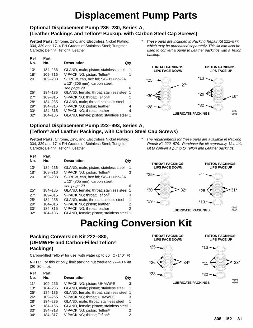
Displacement Pump PartsOptional Displacement Pump 236–230, Series A,(Leather Packings and Teflon � Backup, with Carbon Steel Cap Screws)
Wetted Parts: Chrome, Zinc, and Electroless Nickel Plating;304, 329 and 17–4 PH Grades of Stainless Steel; TungstenCarbide; Delrin�; Teflon�; Leather
Ref PartNo. No. Description Qty
13* 184–236 GLAND, male; piston; stainless steel 118* 109–316 V-PACKING; piston; Teflon� 120 109–203 SCREW, cap, hex hd; 5/8–11 unc–2A
x 12” (305 mm); carbon steel;see page 29 6
25* 184–185 GLAND, female; throat; stainless steel 127* 109–315 V-PACKING; throat; Teflon� 128* 184–235 GLAND, male; throat; stainless steel 129* 184–316 V-PACKING; piston; leather 430* 184–315 V-PACKING; throat; leather 432* 184–186 GLAND, female; piston; stainless steel 1
* These parts are included in Packing Repair Kit 222–877,which may be purchased separately. This kit can also beused to convert a pump to Leather packings with a Teflonbackup.
THROAT PACKINGS:LIPS FACE DOWN
PISTON PACKINGS:LIPS FACE UP
08050806LUBRICATE PACKINGS
*29
*32
18*
*25
*30
27*
*28
*13
Optional Displacement Pump 222–993, Series A,(Teflon � and Leather Packings, with Carbon Steel Cap Screws)
Wetted Parts: Chrome, Zinc, and Electroless Nickel Plating;304, 329 and 17–4 PH Grades of Stainless Steel; TungstenCarbide; Delrin�; Teflon�; Leather
Ref PartNo. No. Description Qty
13* 184–236 GLAND, male; piston; stainless steel 118* 109–316 V-PACKING; piston; Teflon� 320 109–203 SCREW, cap, hex hd; 5/8–11 unc–2A
x 12” (305 mm); carbon steel;see page 29 6
25* 184–185 GLAND, female; throat; stainless steel 127* 109–315 V-PACKING; throat; Teflon� 328* 184–235 GLAND, male; throat; stainless steel 129* 184–316 V-PACKING; piston; leather 230* 184–315 V-PACKING; throat; leather 232* 184–186 GLAND, female; piston; stainless steel 1
* The replacements for these parts are available in PackingRepair Kit 222–879. Purchase the kit separately. Use thiskit to convert a pump to Teflon and Leather packings.
THROAT PACKINGS:LIPS FACE DOWN
PISTON PACKINGS:LIPS FACE UP
08050806LUBRICATE PACKINGS
*28
*13
31*
*25
*30 32*
*29
*11
Packing Conversion KitPacking Conversion Kit 222–880,(UHMWPE and Carbon-Filled Teflon �
Packings)Carbon-filled Teflon� for use with water up to 60� C (140� F)
NOTE: For this kit only, limit packing nut torque to 27–40 N�m(20–30 ft-lb).
Ref PartNo. No. Description Qty
11* 109–266 V-PACKING; piston; UHMWPE 313* 184–236 GLAND, male; piston; stainless steel 125* 184–185 GLAND, female; throat; stainless steel 126* 109–265 V-PACKING; throat; UHMWPE 328* 184–235 GLAND, male; throat; stainless steel 132* 184–186 GLAND, female; piston; stainless steel 133* 184–318 V-PACKING; piston; Teflon� 234* 184–317 V-PACKING; throat; Teflon� 2
THROAT PACKINGS:LIPS FACE DOWN
PISTON PACKINGS:LIPS FACE UP
08050806
*11
*32
33*
*25
*26 34*
*28
*13
LUBRICATE PACKINGS
�� �������
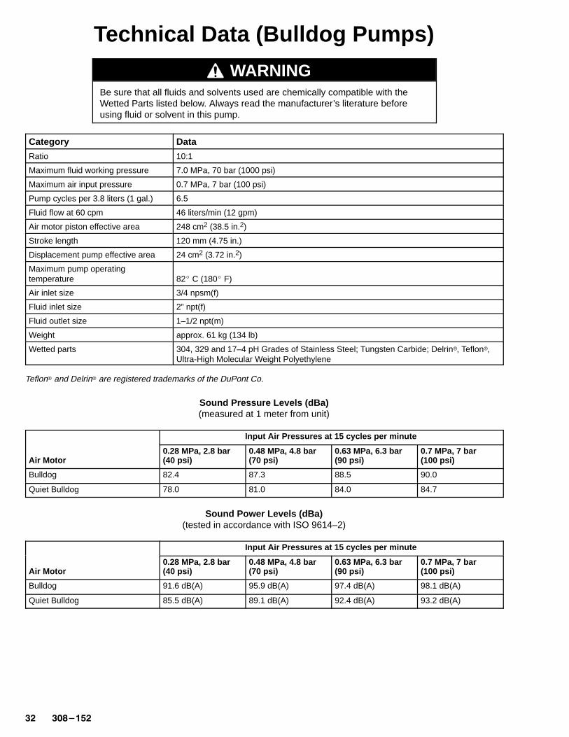
Technical Data (Bulldog Pumps)
WARNINGBe sure that all fluids and solvents used are chemically compatible with theWetted Parts listed below. Always read the manufacturer’s literature beforeusing fluid or solvent in this pump.
Category Data
Ratio 10:1
Maximum fluid working pressure 7.0 MPa, 70 bar (1000 psi)
Maximum air input pressure 0.7 MPa, 7 bar (100 psi)
Pump cycles per 3.8 liters (1 gal.) 6.5
Fluid flow at 60 cpm 46 liters/min (12 gpm)
Air motor piston effective area 248 cm2 (38.5 in.2)
Stroke length 120 mm (4.75 in.)
Displacement pump effective area 24 cm2 (3.72 in.2)
Maximum pump operatingtemperature 82� C (180� F)
Air inlet size 3/4 npsm(f)
Fluid inlet size 2” npt(f)
Fluid outlet size 1–1/2 npt(m)
Weight approx. 61 kg (134 lb)
Wetted parts 304, 329 and 17–4 pH Grades of Stainless Steel; Tungsten Carbide; Delrin�, Teflon�,Ultra-High Molecular Weight Polyethylene
Teflon� and Delrin� are registered trademarks of the DuPont Co.
Sound Pressure Levels (dBa)(measured at 1 meter from unit)
Input Air Pressures at 15 cycles per minute
Air Motor0.28 MPa, 2.8 bar (40 psi)
0.48 MPa, 4.8 bar (70 psi)
0.63 MPa, 6.3 bar (90 psi)
0.7 MPa, 7 bar (100 psi)
Bulldog 82.4 87.3 88.5 90.0
Quiet Bulldog 78.0 81.0 84.0 84.7
Sound Power Levels (dBa)(tested in accordance with ISO 9614–2)
Input Air Pressures at 15 cycles per minute
Air Motor0.28 MPa, 2.8 bar (40 psi)
0.48 MPa, 4.8 bar (70 psi)
0.63 MPa, 6.3 bar (90 psi)
0.7 MPa, 7 bar (100 psi)
Bulldog 91.6 dB(A) 95.9 dB(A) 97.4 dB(A) 98.1 dB(A)
Quiet Bulldog 85.5 dB(A) 89.1 dB(A) 92.4 dB(A) 93.2 dB(A)
������ ��
Technical Data (Bulldog Pumps)
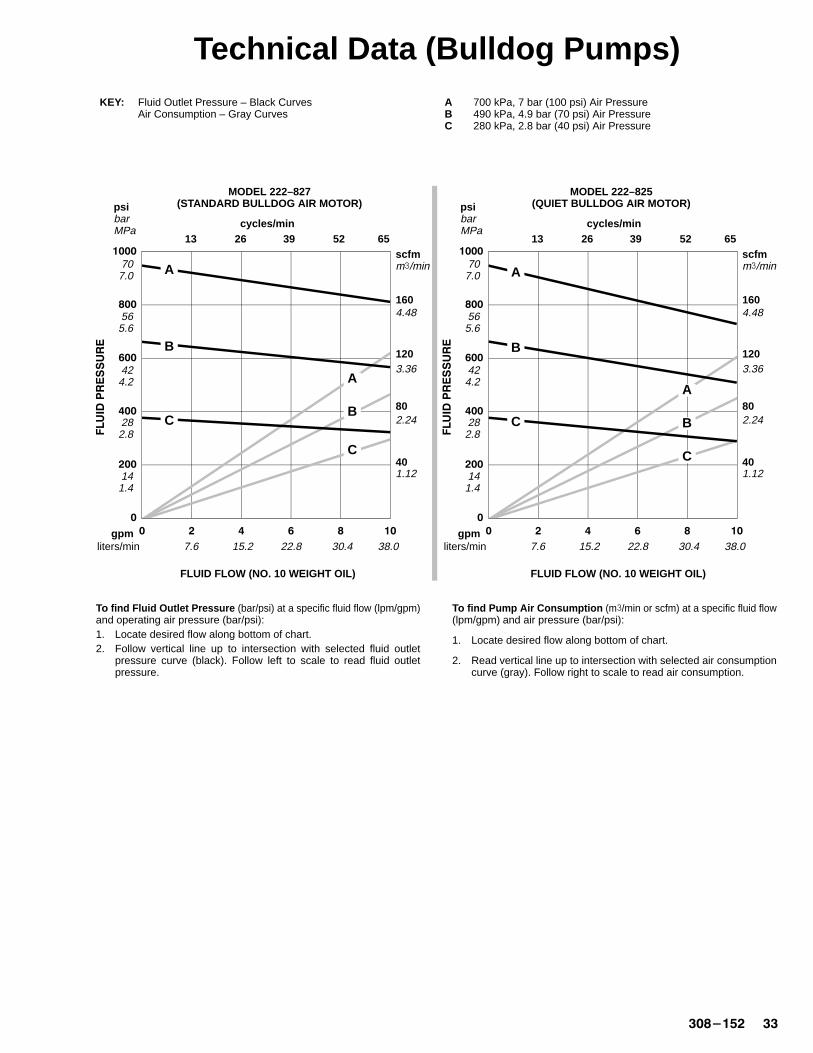
To find Fluid Outlet Pressure (bar/psi) at a specific fluid flow (lpm/gpm)and operating air pressure (bar/psi):1. Locate desired flow along bottom of chart.2. Follow vertical line up to intersection with selected fluid outlet
pressure curve (black). Follow left to scale to read fluid outletpressure.
To find Pump Air Consumption (m�/min or scfm) at a specific fluid flow(lpm/gpm) and air pressure (bar/psi):
1. Locate desired flow along bottom of chart.
2. Read vertical line up to intersection with selected air consumptioncurve (gray). Follow right to scale to read air consumption.
KEY: Fluid Outlet Pressure – Black Curves A 700 kPa, 7 bar (100 psi) Air PressureAir Consumption – Gray Curves B 490 kPa, 4.9 bar (70 psi) Air Pressure
C 280 kPa, 2.8 bar (40 psi) Air Pressure
MODEL 222–827(STANDARD BULLDOG AIR MOT OR)
MODEL 222–825(QUIET BULLDOG AIR MOT OR)
�
���
���
���
��
����
� � � � ��
FLUID FLOW (NO. 10 WEIGHT OIL)
psibarMPa
gpmliters/min
cycles/min
scfmm�/min
40
80
120
7.6
1.12
2.24
3.36
13 26 65
15.2 22.8 30.4
141.4
707.0
52
1604.48
A
B
C
A
B
C
565.6
424.2
38.0
39
FLUID FLOW (NO. 10 WEIGHT OIL)
282.8
�
���
���
���
��
����
� � � � ��
psibarMPa
gpmliters/min
cycles/min
scfmm�/min
40
80
120
7.6
1.12
2.24
3.36
13 26 65
15.2 22.8 30.4
141.4
707.0
52
1604.48
A
B
C
A
B
C
565.6
424.2
38.0
39
282.8

�� �������
Technical Data (King Pumps)
WARNINGBe sure that all fluids and solvents used are chemically compatible with theWetted Parts listed below. Always read the manufacturer’s literature beforeusing fluid or solvent in this pump.
Category Data
Ratio 20:1
Maximum fluid working pressure 12.0 MPa, 124 bar (1800 psi)
Maximum air input pressure 0.6 MPa, 6.2 bar (90 psi)
Pump cycles per 3.8 liters (1 gal.) 6.5
Fluid flow at 50 cpm 46 liters/min (12 gpm)
Air motor piston effective area 506 cm2 (78.5 in.2)
Stroke length 120 mm (4.75 in.)
Displacement pump effective area 24 cm2 (3.72 in.2)
Maximum pump operatingtemperature 82� C (180� F)
Air inlet size 3/4 npsm(f)
Fluid inlet size 2” npt(f)
Fluid outlet size 1–1/2” npt(m)
Weight approx. 69 kg (162 lb)
Wetted parts 304, 329 and 17–4 pH Grades of Stainless Steel; Tungsten Carbide; Delrin�, Teflon�,Ultra-High Molecular Weight Polyethylene
Teflon� and Delrin� are registered trademarks of the DuPont Co.
Sound Pressure Levels (dBa)(measured at 1 meter from unit)
Input Air Pressures at 15 cycles per minute
Air Motor0.28 MPa, 2.8 bar (40 psi)
0.48 MPa, 4.8 bar (70 psi)
0.63 MPa, 6.3 bar (90 psi)
King 78.8 82.7 90.5
Quiet King 77.9 79.2 87.5
Sound Power Levels (dBa)(tested in accordance with ISO 9614–2)
Input Air Pressures at 15 cycles per minute
Air Motor0.28 MPa, 2.8 bar (40 psi)
0.48 MPa, 4.8 bar (70 psi)
0.63 MPa, 6.3 bar (90 psi)
King 86.5 88.8 97.7
Quiet King 85.2 86.6 95.2
������ ��
Technical Data (King Pumps)
�
���
���
��
����
����
���
� � � � ��
FLUID FLOW (NO. 10 WEIGHT OIL)
psibarMPa
gpmliters/min
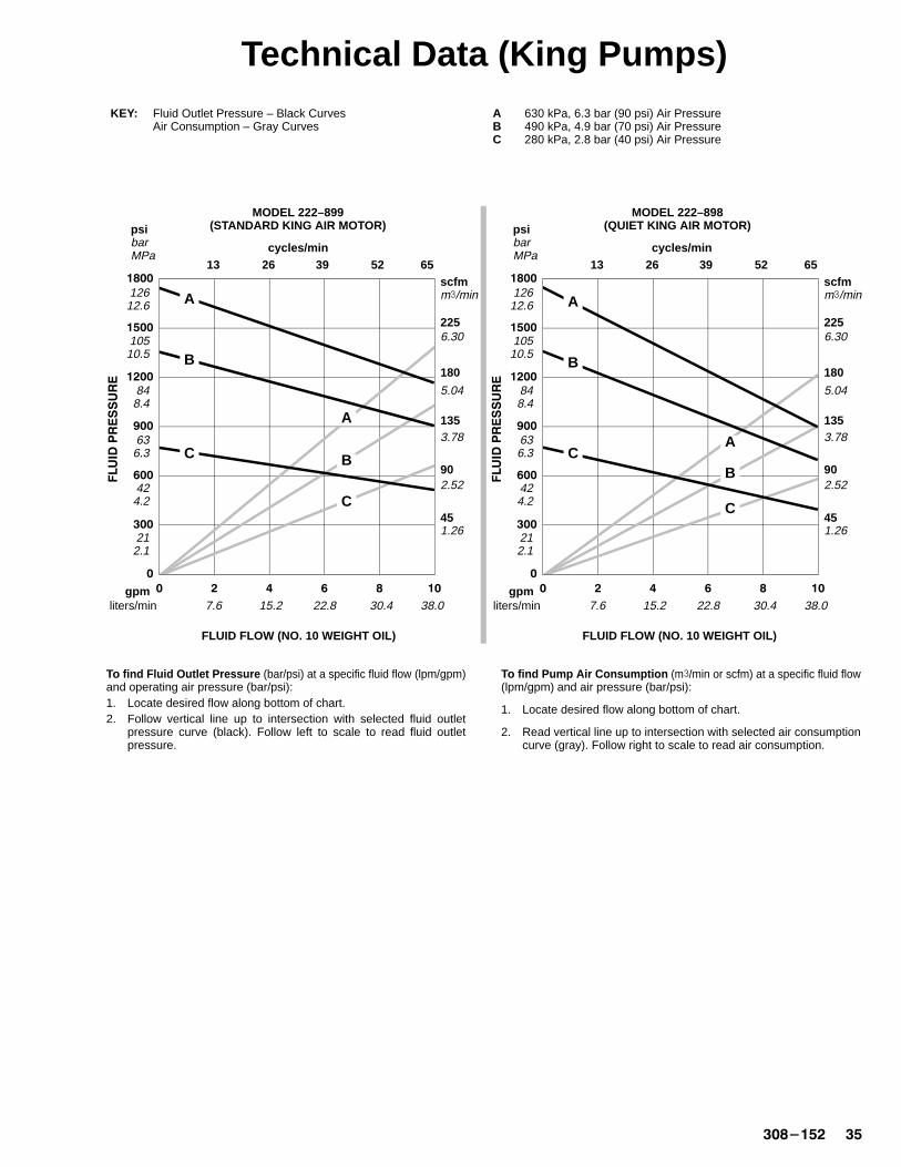
To find Fluid Outlet Pressure (bar/psi) at a specific fluid flow (lpm/gpm)and operating air pressure (bar/psi):1. Locate desired flow along bottom of chart.2. Follow vertical line up to intersection with selected fluid outlet
pressure curve (black). Follow left to scale to read fluid outletpressure.
To find Pump Air Consumption (m�/min or scfm) at a specific fluid flow(lpm/gpm) and air pressure (bar/psi):
1. Locate desired flow along bottom of chart.
2. Read vertical line up to intersection with selected air consumptioncurve (gray). Follow right to scale to read air consumption.
cycles/min
scfmm�/min
45
90
135
7.6
1.26
2.52
3.78
13 26 65
KEY: Fluid Outlet Pressure – Black Curves A 630 kPa, 6.3 bar (90 psi) Air PressureAir Consumption – Gray Curves B 490 kPa, 4.9 bar (70 psi) Air Pressure
C 280 kPa, 2.8 bar (40 psi) Air Pressure
180
5.04
15.2 22.8 30.4
212.1
848.4
52
10510.5
12612.6
2256.30
A
B
C
A
B
C
MODEL 222–899(STANDARD KING AIR MOT OR)
FLUID FLOW (NO. 10 WEIGHT OIL)
MODEL 222–898(QUIET KING AIR MOTOR)
636.3
424.2
38.0
39
�
���
���
��
����
����
���
� � � � ��
psibarMPa
gpmliters/min
cycles/min
scfmm�/min
45
90
135
7.6
1.26
2.52
3.78
13 26 65
180
5.04
15.2 22.8 30.4
212.1
848.4
52
10510.5
12612.6
2256.30
A
B
CA
B
C
636.3
424.2
38.0
39
�� �������
Technical Data (Premier Pump)
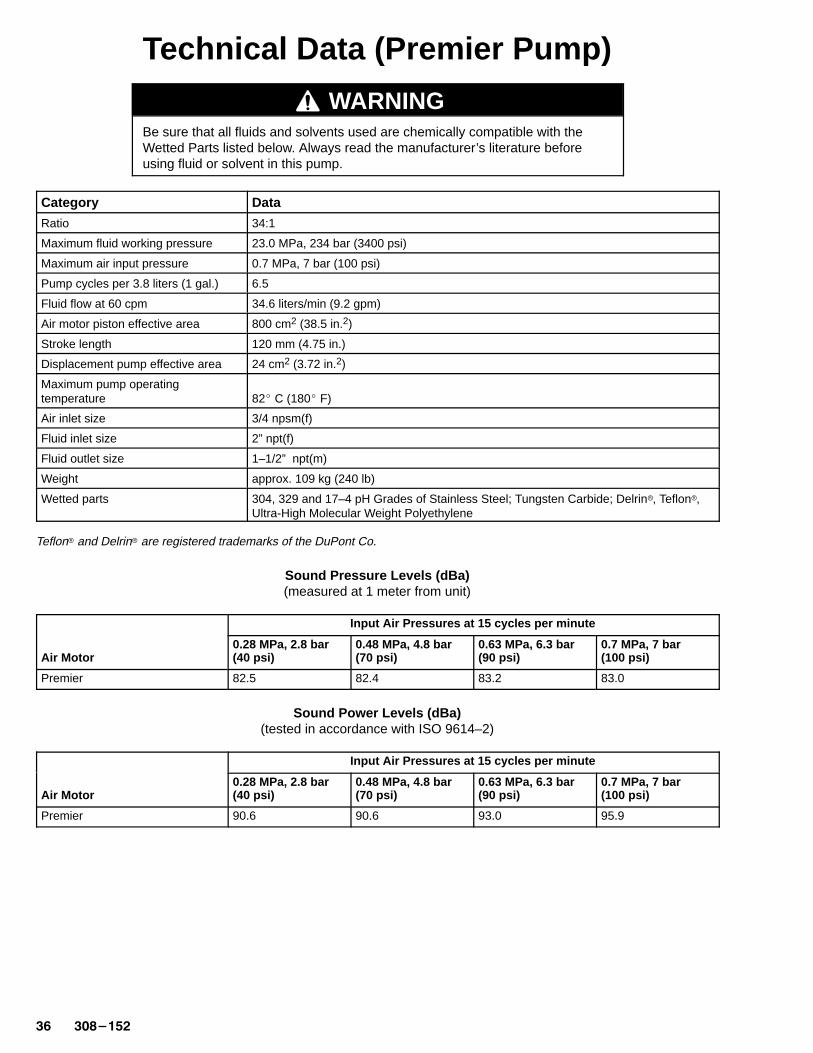
WARNINGBe sure that all fluids and solvents used are chemically compatible with theWetted Parts listed below. Always read the manufacturer’s literature beforeusing fluid or solvent in this pump.
Category Data
Ratio 34:1
Maximum fluid working pressure 23.0 MPa, 234 bar (3400 psi)
Maximum air input pressure 0.7 MPa, 7 bar (100 psi)
Pump cycles per 3.8 liters (1 gal.) 6.5
Fluid flow at 60 cpm 34.6 liters/min (9.2 gpm)
Air motor piston effective area 800 cm2 (38.5 in.2)
Stroke length 120 mm (4.75 in.)
Displacement pump effective area 24 cm2 (3.72 in.2)
Maximum pump operatingtemperature 82� C (180� F)
Air inlet size 3/4 npsm(f)
Fluid inlet size 2” npt(f)
Fluid outlet size 1–1/2” npt(m)
Weight approx. 109 kg (240 lb)
Wetted parts 304, 329 and 17–4 pH Grades of Stainless Steel; Tungsten Carbide; Delrin�, Teflon�,Ultra-High Molecular Weight Polyethylene
Teflon� and Delrin� are registered trademarks of the DuPont Co.
Sound Pressure Levels (dBa)(measured at 1 meter from unit)
Input Air Pressures at 15 cycles per minute
Air Motor0.28 MPa, 2.8 bar (40 psi)
0.48 MPa, 4.8 bar (70 psi)
0.63 MPa, 6.3 bar (90 psi)
0.7 MPa, 7 bar (100 psi)
Premier 82.5 82.4 83.2 83.0
Sound Power Levels (dBa)(tested in accordance with ISO 9614–2)
Input Air Pressures at 15 cycles per minute
Air Motor0.28 MPa, 2.8 bar (40 psi)
0.48 MPa, 4.8 bar (70 psi)
0.63 MPa, 6.3 bar (90 psi)
0.7 MPa, 7 bar (100 psi)
Premier 90.6 90.6 93.0 95.9
������ �
Technical Data (Premier Pump)
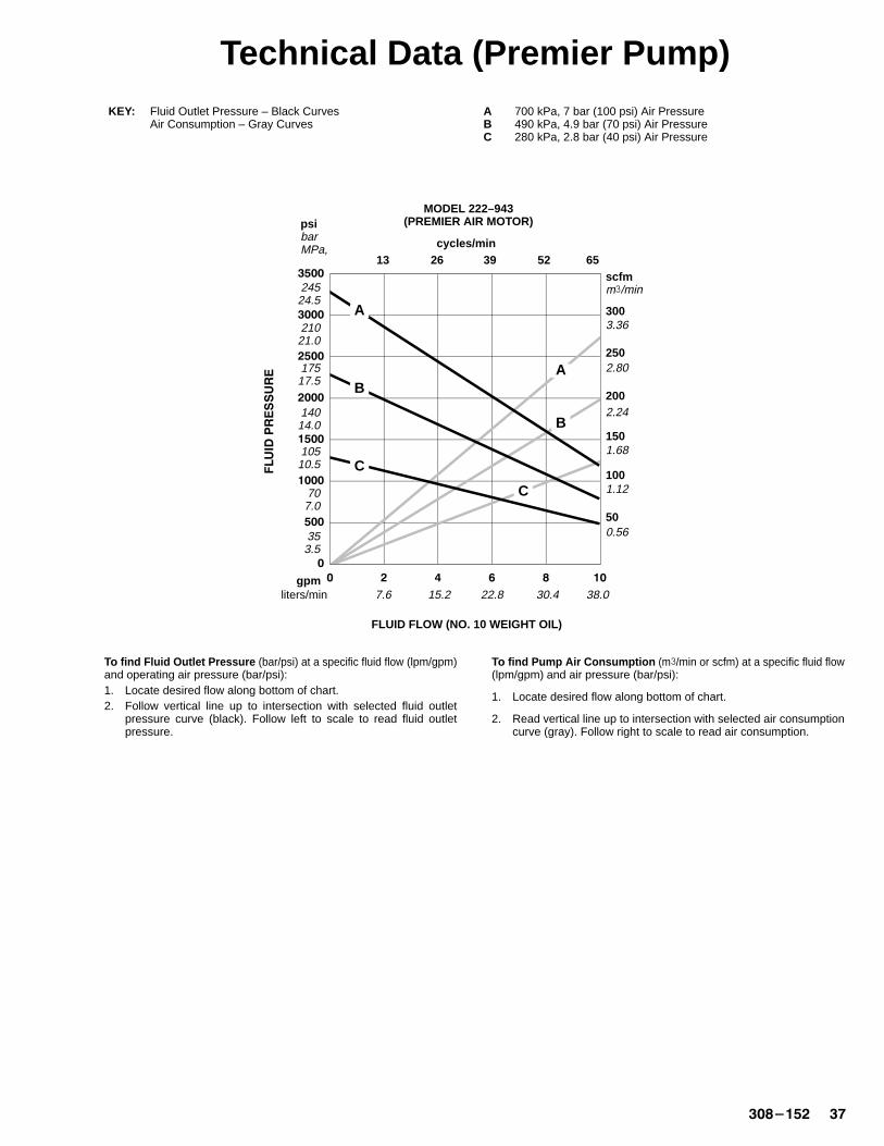
To find Fluid Outlet Pressure (bar/psi) at a specific fluid flow (lpm/gpm)and operating air pressure (bar/psi):1. Locate desired flow along bottom of chart.2. Follow vertical line up to intersection with selected fluid outlet
pressure curve (black). Follow left to scale to read fluid outletpressure.
To find Pump Air Consumption (m�/min or scfm) at a specific fluid flow(lpm/gpm) and air pressure (bar/psi):
1. Locate desired flow along bottom of chart.
2. Read vertical line up to intersection with selected air consumptioncurve (gray). Follow right to scale to read air consumption.
KEY: Fluid Outlet Pressure – Black Curves A 700 kPa, 7 bar (100 psi) Air PressureAir Consumption – Gray Curves B 490 kPa, 4.9 bar (70 psi) Air Pressure
C 280 kPa, 2.8 bar (40 psi) Air Pressure
MODEL 222–943(PREMIER AIR MOTOR)
�
���
����
����
����
����
����
����
� � � � ��
FLUID FLOW (NO. 10 WEIGHT OIL)
psibarMPa,
gpmliters/min
cycles/min
scfmm�/min
100
250
200
7.6
1.12
2.80
2.24
13 26 65
15.2 22.8 30.4
353.5
707.0
52
3003.36
A
B
C
A
B
C
38.0
39
10510.5
14014.0
17517.5
21021.0
24524.5
500.56
1501.68
�� �������
Technical Data (Viscount Pump)
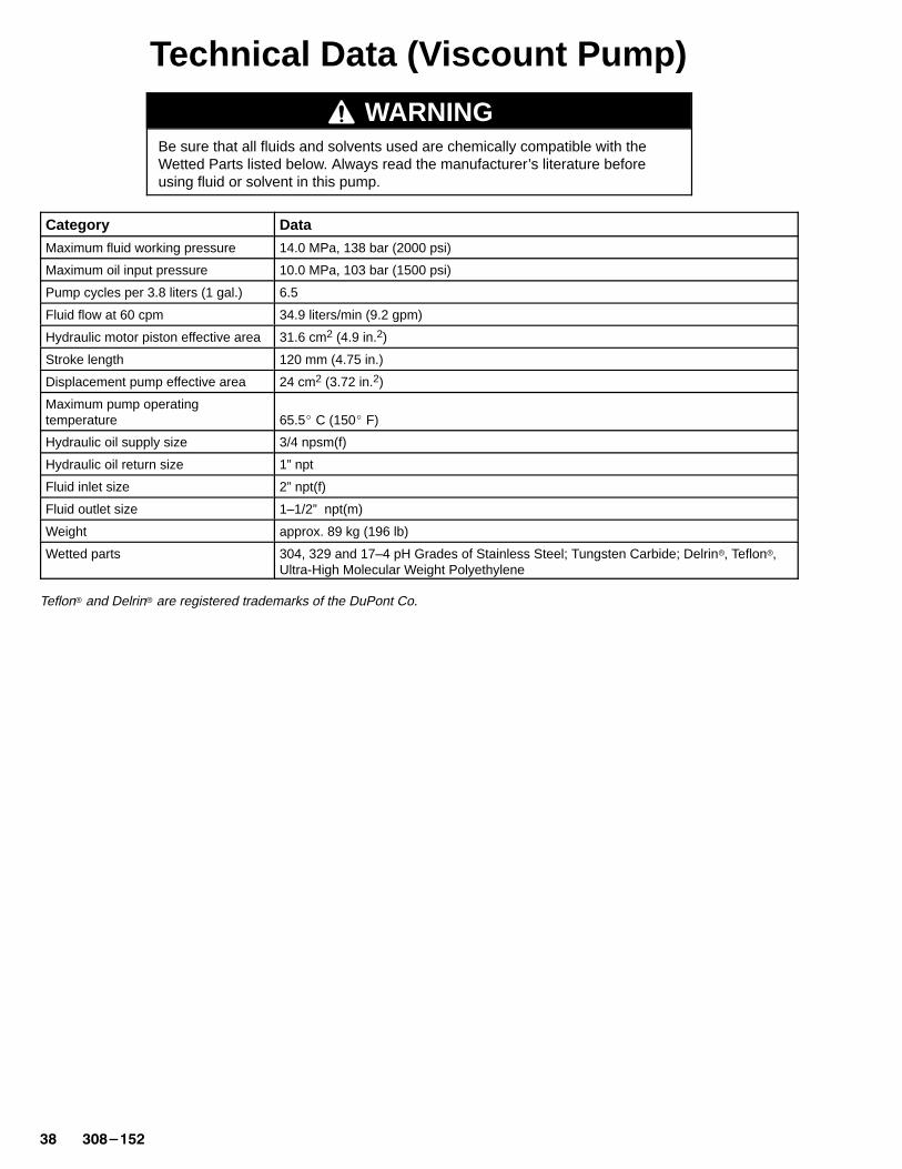
WARNINGBe sure that all fluids and solvents used are chemically compatible with theWetted Parts listed below. Always read the manufacturer’s literature beforeusing fluid or solvent in this pump.
Category Data
Maximum fluid working pressure 14.0 MPa, 138 bar (2000 psi)
Maximum oil input pressure 10.0 MPa, 103 bar (1500 psi)
Pump cycles per 3.8 liters (1 gal.) 6.5
Fluid flow at 60 cpm 34.9 liters/min (9.2 gpm)
Hydraulic motor piston effective area 31.6 cm2 (4.9 in.2)
Stroke length 120 mm (4.75 in.)
Displacement pump effective area 24 cm2 (3.72 in.2)
Maximum pump operatingtemperature 65.5� C (150� F)
Hydraulic oil supply size 3/4 npsm(f)
Hydraulic oil return size 1” npt
Fluid inlet size 2” npt(f)
Fluid outlet size 1–1/2” npt(m)
Weight approx. 89 kg (196 lb)
Wetted parts 304, 329 and 17–4 pH Grades of Stainless Steel; Tungsten Carbide; Delrin�, Teflon�,Ultra-High Molecular Weight Polyethylene
Teflon� and Delrin� are registered trademarks of the DuPont Co.
������ �
Technical Data (Viscount Pump)
�
���
��
����
����
����
� � � � ��
psibarMPa
gpmliters/min
cycles/min
4
8
12
7.6
15.2
30.4
45.6
13 26 65
1660.8
15.2 22.8 38.0
282.8
565.6
848.4
52
11211.2
14014.0 A
B
C
FLUID FLOW (NO. 10 WEIGHT OIL)
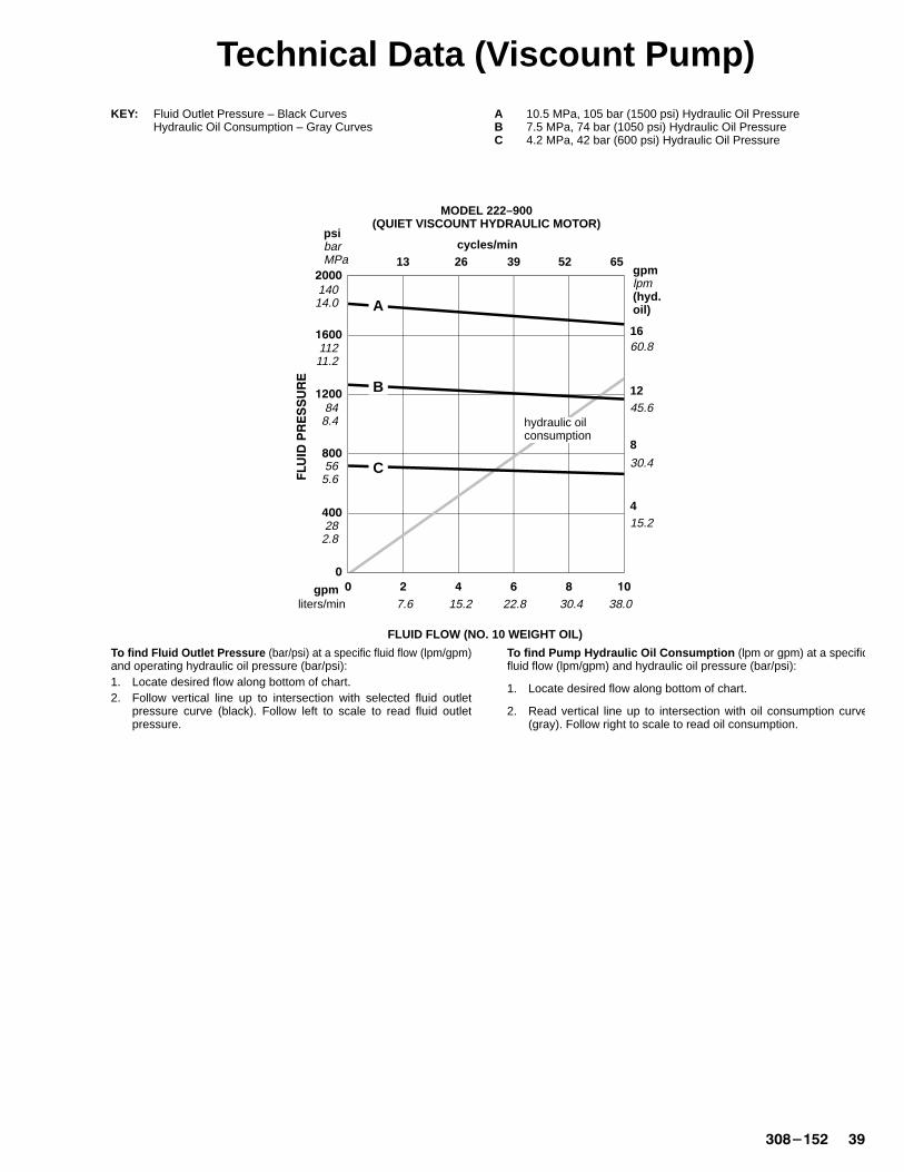
To find Fluid Outlet Pressure (bar/psi) at a specific fluid flow (lpm/gpm)and operating hydraulic oil pressure (bar/psi):1. Locate desired flow along bottom of chart.2. Follow vertical line up to intersection with selected fluid outlet
pressure curve (black). Follow left to scale to read fluid outletpressure.
To find Pump Hydraulic Oil Consumption (lpm or gpm) at a specificfluid flow (lpm/gpm) and hydraulic oil pressure (bar/psi):
1. Locate desired flow along bottom of chart.
2. Read vertical line up to intersection with oil consumption curve(gray). Follow right to scale to read oil consumption.
hydraulic oilconsumption
KEY: Fluid Outlet Pressure – Black Curves A 10.5 MPa, 105 bar (1500 psi) Hydraulic Oil PressureHydraulic Oil Consumption – Gray Curves B 7.5 MPa, 74 bar (1050 psi) Hydraulic Oil Pressure
C 4.2 MPa, 42 bar (600 psi) Hydraulic Oil Pressure
gpmlpm(hyd.oil)
30.4
39
MODEL 222–900(QUIET VISCOUNT HYDRAULIC MOTOR)
�� �������
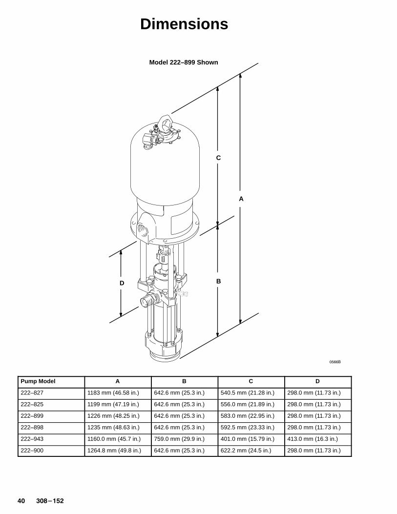
Dimensions
Model 222–899 Shown
A
B
C
D
�����
Pump Model A B C D
222–827 1183 mm (46.58 in.) 642.6 mm (25.3 in.) 540.5 mm (21.28 in.) 298.0 mm (11.73 in.)
222–825 1199 mm (47.19 in.) 642.6 mm (25.3 in.) 556.0 mm (21.89 in.) 298.0 mm (11.73 in.)
222–899 1226 mm (48.25 in.) 642.6 mm (25.3 in.) 583.0 mm (22.95 in.) 298.0 mm (11.73 in.)
222–898 1235 mm (48.63 in.) 642.6 mm (25.3 in.) 592.5 mm (23.33 in.) 298.0 mm (11.73 in.)
222–943 1160.0 mm (45.7 in.) 759.0 mm (29.9 in.) 401.0 mm (15.79 in.) 413.0 mm (16.3 in.)
222–900 1264.8 mm (49.8 in.) 642.6 mm (25.3 in.) 622.2 mm (24.5 in.) 298.0 mm (11.73 in.)
������� ��
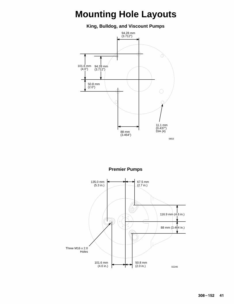
Mounting Hole Layouts
88 mm(3.464”)
94.28 mm(3.712”)
11.1 mm(0.437”)DIA (4)
94.28 mm(3.712”)
101.6 mm(4.0”)
50.8 mm(2.0”)
0653
02246
67.5 mm(2.7 in.)
135.0 mm(5.3 in.)
50.8 mm(2.0 in.)
101.6 mm(4.0 in.)
116.9 mm (4.6 in.)
88 mm (3.464 in.)
Three M16 x 2.0Holes
Premier Pumps
King, Bulldog, and Viscount Pumps

�� �������
Notes
������� ��
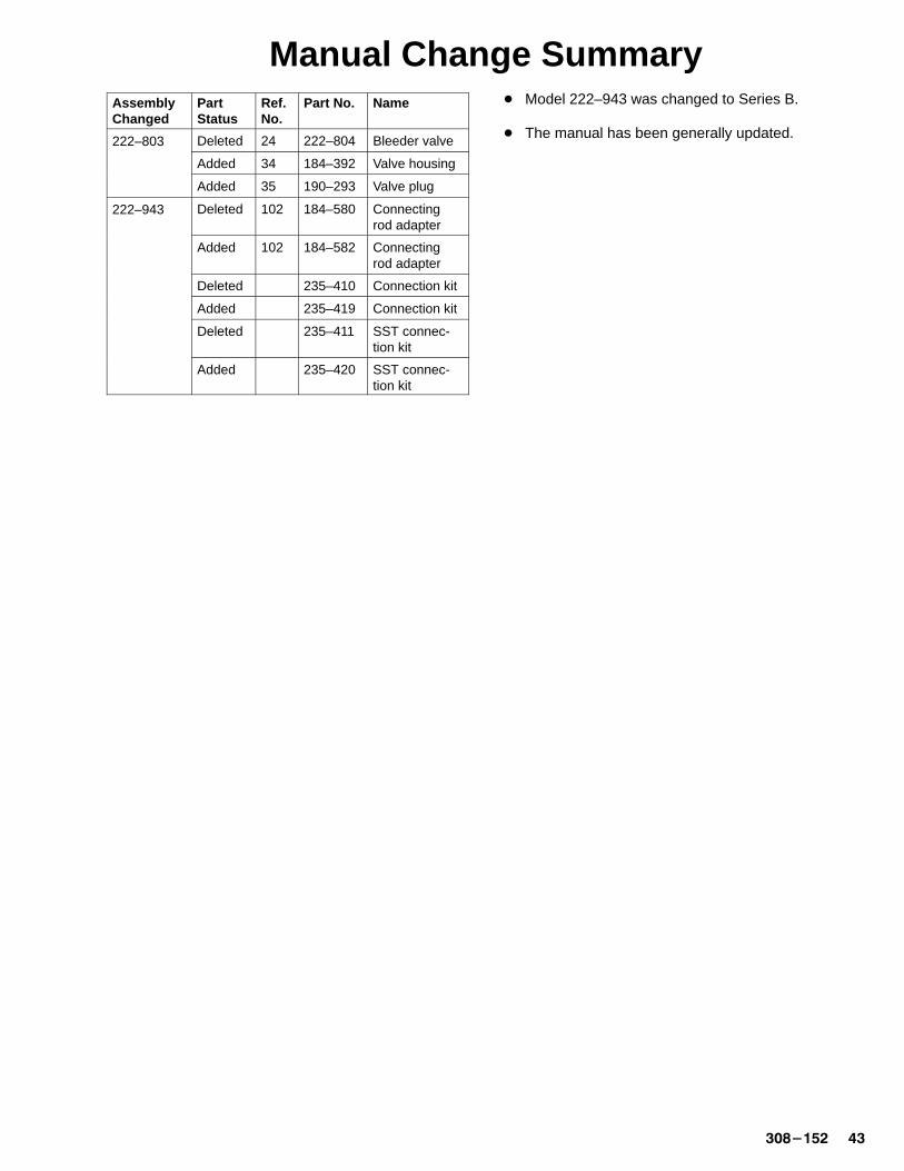
Manual Change SummaryAssemblyChanged
PartStatus
Ref.No.
Part No. Name
222–803 Deleted 24 222–804 Bleeder valve222 803
Added 34 184–392 Valve housing
Added 35 190–293 Valve plug
222–943 Deleted 102 184–580 Connectingrod adapter
Added 102 184–582 Connectingrod adapter
Deleted 235–410 Connection kit
Added 235–419 Connection kit
Deleted 235–411 SST connec-tion kit
Added 235–420 SST connec-tion kit
� Model 222–943 was changed to Series B.
� The manual has been generally updated.
�� �������
Graco WarrantyGraco warrants all equipment listed in this manual which is manufactured by Graco and bearing its name to be free from defects inmaterial and workmanship on the date of sale by an authorized Graco distributor to the original purchaser for use. With the exception ofany special extended or limited warranty published by Graco, Graco will, for a period of twelve months from the date of sale, repair orreplace any part of the equipment determined by Graco to be defective. This warranty applies only when the equipment is installed,operated and maintained in accordance with Graco’s written recommendations.
This warranty does not cover, and Graco shall not be liable for general wear and tear, or any malfunction, damage or wear caused byfaulty installation, misapplication, abrasion, corrosion, inadequate or improper maintenance, negligence, accident, tampering, orsubstitution of non-Graco component parts. Nor shall Graco be liable for malfunction, damage or wear caused by the incompatibility ofGraco equipment with structures, accessories, equipment or materials not supplied by Graco, or the improper design, manufacture,installation, operation or maintenance or structures, accessories, equipment or materials not supplied by Graco.
This warranty is conditioned upon the prepaid return of the equipment claimed to be defective to an authorized Graco distributor forverification of the claimed defect. If the claimed defect is verified, Graco will repair or replace free of charge any defective parts. Theequipment will be returned to the original purchaser transportation prepaid. If inspection of the equipment does not disclose any defectin material or workmanship, repairs will be made at a reasonable charge, which charges may include the costs of parts, labor, andtransportation.
Graco’s sole obligation and buyer’s sole remedy for any breach of warranty shall be as set forth above. The buyer agrees that no otherremedy (including, but not limited to, incidental or consequential damages for lost profits, lost sales, injury to person or property, or anyother incidental or consequential loss) shall be available. Any action for breach of warranty must be brought within two (2) years of thedate of sale.
GRACO MAKES NO WARRANTY, AND DISCLAIMS ALL IMPLIED WARRANTIES OF MERCHANTABILITY AND FITNESS FORA PARTICULAR PURPOSE IN CONNECTION WITH ACCESSORIES, EQUIPMENT, MATERIALS OR COMPONENTS SOLD BUTNOT MANUFACTURED BY GRACO. These items sold, but not manufactured by Graco (such as electric motors, gas engines,switches, hose, etc.), are subject to the warranty, if any, of their manufacturer. Graco will provide purchaser with reasonable assistancein making any claim for breach of these warranties.
In no event will Graco be liable for indirect, incidental, special or consequential damages resulting from Graco supplying equipmenthereunder, or the furnishing, performance, or use of any products or other goods sold hereto, whether due to a breach of contract,breach of warranty, the negligence of Graco, or otherwise.
FOR GRACO CANADA CUST OMERSThe parties acknowledge that they have required that the present document, as well as all documents, notices and legal proceedingsentered into, given or instituted pursuant hereto or relating directly or indirectly hereto, be drawn up in English. Les partiesreconnaissent avoir convenu que la rédaction du présente document sera en Anglais, ainsi que tous documents, avis et procéduresjudiciaires exécutés, donnés ou intentés à la suite de ou en rapport, directement ou indirectement, avec les procédures concernées.
Graco Phone NumberTO PLACE AN ORDER , contact your Graco distributor, or call this number to identify the distributor closest to you:
1–800–367–4023 Toll Free
All written and visual data contained in this document reflects the latest product information available at the time of publication.Graco reserves the right to make changes at any time without notice.
Sales Offices: Minneapolis, Detroit, Los AngelesForeign Offices: Belgium, Canada, England, Korea, France, Germany, Hong Kong, Japan
GRACO INC. P.O. BOX 1441 MINNEAPOLIS, MN 55440–1441PRINTED IN U.S.A. 308–152 June 1992, Revised July 1997