Embed Size (px)
Citation preview

FCIA Firestop Manual of Practice Page 2.4 - 1 Date of Issue: 12/29/2008
2.4 PERIMETER FIRE CONTAINMENT A Perimeter Fire Barrier System is a specific assembly consisting of a fire resistance rated or non resistance-rated wall, the adjacent fire resistance rated floor and the sealing mechanism used to close the void between them at the interior of the building. The total system including the curtain wall, insulation, joint size, floor slab and perimeter fire barrier system (firestopping) attains a resistance rating for fire, and measurements to evaluate smoke via air leakage testing, and resistance to temperature rise on the non fire side of the assembly, as specified by the design from the specific testing laboratory. As with other penetration and joint firestop systems, proper design, exacting zero tolerance installation and inspection procedures must be followed to result in a system installed to the classified design. Testing takes place with the curtain wall at the maximum clearance distance from the floor.
Graphic courtesy of 3M Fire Protection Products The intent of these perimeter fire barrier systems is to prevent the vertical passage of flame and hot gasses, (smoke if tested for air leakage L-Rating at ambient and 400F), through this perimeter void created at the edge of a floor assembly and the wall. These systems prevent the spread of flame and hot gasses from a lower floor to the interior space of the upper floor for a measured duration of time.
PERIMETER FIRE BARRIER SYSTEMS
Rated Concrete Floor
Assembly
Non-rated Curtain Wall
Perimeter Joint
FCIA Firestop Manual of Practice Page 2.4 - 2 Date of Issue: 12/29/2008
Traditionally in years past, sealing the perimeter void between the floor and the exterior wall has been referred to as “safing the slot”. Depending on the type of curtain wall system, this slot or perimeter void can range from 1” to 8” or more.
Mineral wool fiber orientation must be followed as listed in the classified system design. Photo courtesy of Firestop Solutions, Inc.
Mineral wool backing is compressed into place, oriented properly, with smooth surface to accept Spray or sealant. Photo courtesy of Firestop Solutions, Inc.
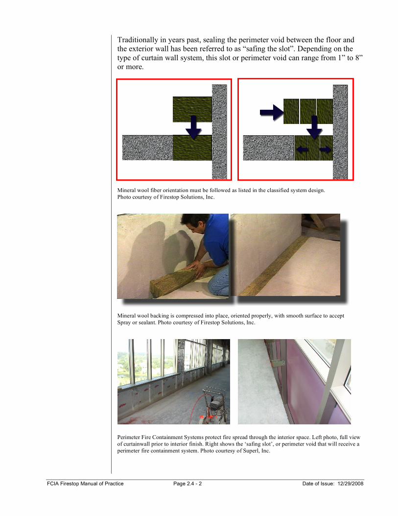
Perimeter Fire Containment Systems protect fire spread through the interior space. Left photo, full view of curtainwall prior to interior finish. Right shows the ‘safing slot’, or perimeter void that will receive a perimeter fire containment system. Photo courtesy of Superl, Inc.
FCIA Firestop Manual of Practice Page 2.4 - 3 Date of Issue: 12/29/2008
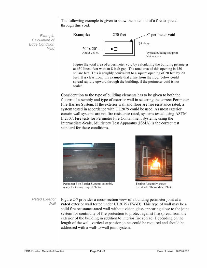
The following example is given to show the potential of a fire to spread through this void.
Example: 250 feet 8” perimeter void 75 feet 20’ x 20’ About 2 ½ % Typical building footprint Not to scale Figure the total area of a perimeter void by calculating the building perimeter at 650 lineal feet with an 8 inch gap. The total area of this opening is 430 square feet. This is roughly equivalent to a square opening of 20 feet by 20 feet. It is clear from this example that a fire from the floor below could spread rapidly upward through the building, if the perimeter void is not sealed.
Consideration to the type of building elements has to be given to both the floor/roof assembly and type of exterior wall in selecting the correct Perimeter Fire Barrier System. If the exterior wall and floor are fire resistance rated, a system tested in accordance with UL2079 could be used. As most exterior curtain wall systems are not fire resistance rated, systems tested using ASTM E 2307, Fire tests for Perimeter Fire Containment Systems, using the Intermediate-Scale, Multistory Test Apparatus (ISMA) is the correct test standard for these conditions.
Perimeter Fire Barrier Systems assembly Testing Assembly shows ready for testing. Superl Photo fire attack. Thermafiber Photo Figure 2-7 provides a cross-section view of a building perimeter joint at a rated exterior wall tested under UL2079 (FW-D). This type of wall may be a solid fire resistance-rated wall without vision glass appearing close to the joint system for continuity of fire protection to protect against fire spread from the exterior of the building in addition to interior fire spread. Depending on the length of the wall, vertical expansion joints could be required and should be addressed with a wall-to-wall joint system.
Example Calculation of
Edge Condition Void
Rated Exterior Wall
FCIA Firestop Manual of Practice Page 2.4 - 4 Date of Issue: 12/29/2008
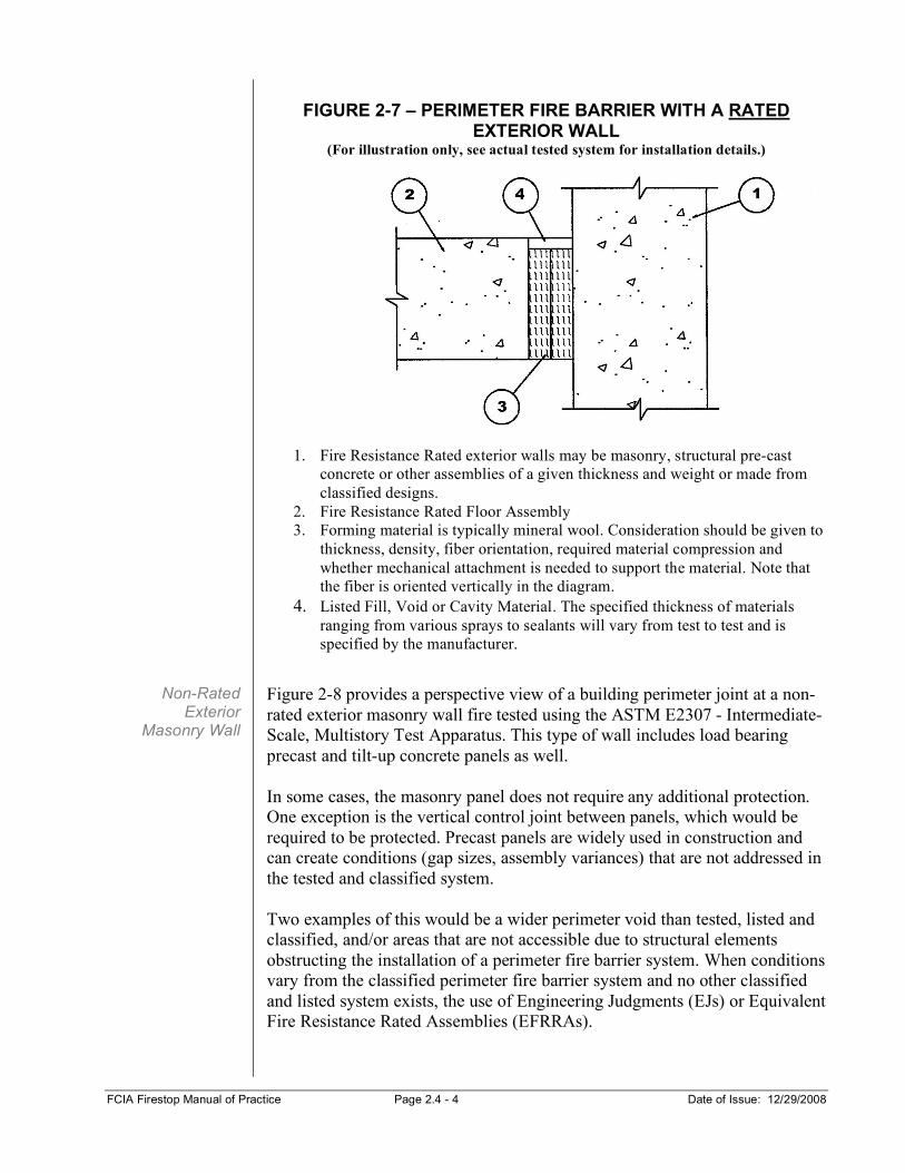
FIGURE 2-7 – PERIMETER FIRE BARRIER WITH A RATED
EXTERIOR WALL (For illustration only, see actual tested system for installation details.)
1. Fire Resistance Rated exterior walls may be masonry, structural pre-cast
concrete or other assemblies of a given thickness and weight or made from classified designs.
2. Fire Resistance Rated Floor Assembly 3. Forming material is typically mineral wool. Consideration should be given to
thickness, density, fiber orientation, required material compression and whether mechanical attachment is needed to support the material. Note that the fiber is oriented vertically in the diagram.
4. Listed Fill, Void or Cavity Material. The specified thickness of materials ranging from various sprays to sealants will vary from test to test and is specified by the manufacturer.
Figure 2-8 provides a perspective view of a building perimeter joint at a non-rated exterior masonry wall fire tested using the ASTM E2307 - Intermediate-Scale, Multistory Test Apparatus. This type of wall includes load bearing precast and tilt-up concrete panels as well. In some cases, the masonry panel does not require any additional protection. One exception is the vertical control joint between panels, which would be required to be protected. Precast panels are widely used in construction and can create conditions (gap sizes, assembly variances) that are not addressed in the tested and classified system. Two examples of this would be a wider perimeter void than tested, listed and classified, and/or areas that are not accessible due to structural elements obstructing the installation of a perimeter fire barrier system. When conditions vary from the classified perimeter fire barrier system and no other classified and listed system exists, the use of Engineering Judgments (EJs) or Equivalent Fire Resistance Rated Assemblies (EFRRAs).
Non-Rated Exterior
Masonry Wall
FCIA Firestop Manual of Practice Page 2.4 - 5 Date of Issue: 12/29/2008
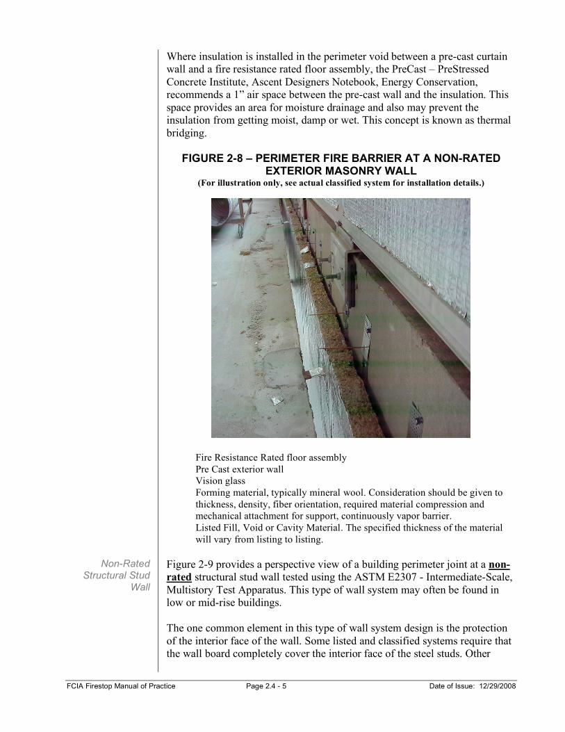
Where insulation is installed in the perimeter void between a pre-cast curtain wall and a fire resistance rated floor assembly, the PreCast – PreStressed Concrete Institute, Ascent Designers Notebook, Energy Conservation, recommends a 1” air space between the pre-cast wall and the insulation. This space provides an area for moisture drainage and also may prevent the insulation from getting moist, damp or wet. This concept is known as thermal bridging.
FIGURE 2-8 – PERIMETER FIRE BARRIER AT A NON-RATED EXTERIOR MASONRY WALL
(For illustration only, see actual classified system for installation details.)
Fire Resistance Rated floor assembly Pre Cast exterior wall Vision glass Forming material, typically mineral wool. Consideration should be given to thickness, density, fiber orientation, required material compression and mechanical attachment for support, continuously vapor barrier. Listed Fill, Void or Cavity Material. The specified thickness of the material will vary from listing to listing.
Figure 2-9 provides a perspective view of a building perimeter joint at a non-rated structural stud wall tested using the ASTM E2307 - Intermediate-Scale, Multistory Test Apparatus. This type of wall system may often be found in low or mid-rise buildings. The one common element in this type of wall system design is the protection of the interior face of the wall. Some listed and classified systems require that the wall board completely cover the interior face of the steel studs. Other
Non-Rated Structural Stud
Wall
FCIA Firestop Manual of Practice Page 2.4 - 6 Date of Issue: 12/29/2008
systems only require the wall board to be installed above and below the perimeter void (safing joint) as shown in illustration below. Note: careful review and consideration must be given to the location or termination of the wall board to the studs below the floor slab. This must be done to insure that the proper listed and classified perimeter fire barrier protection system is installed.
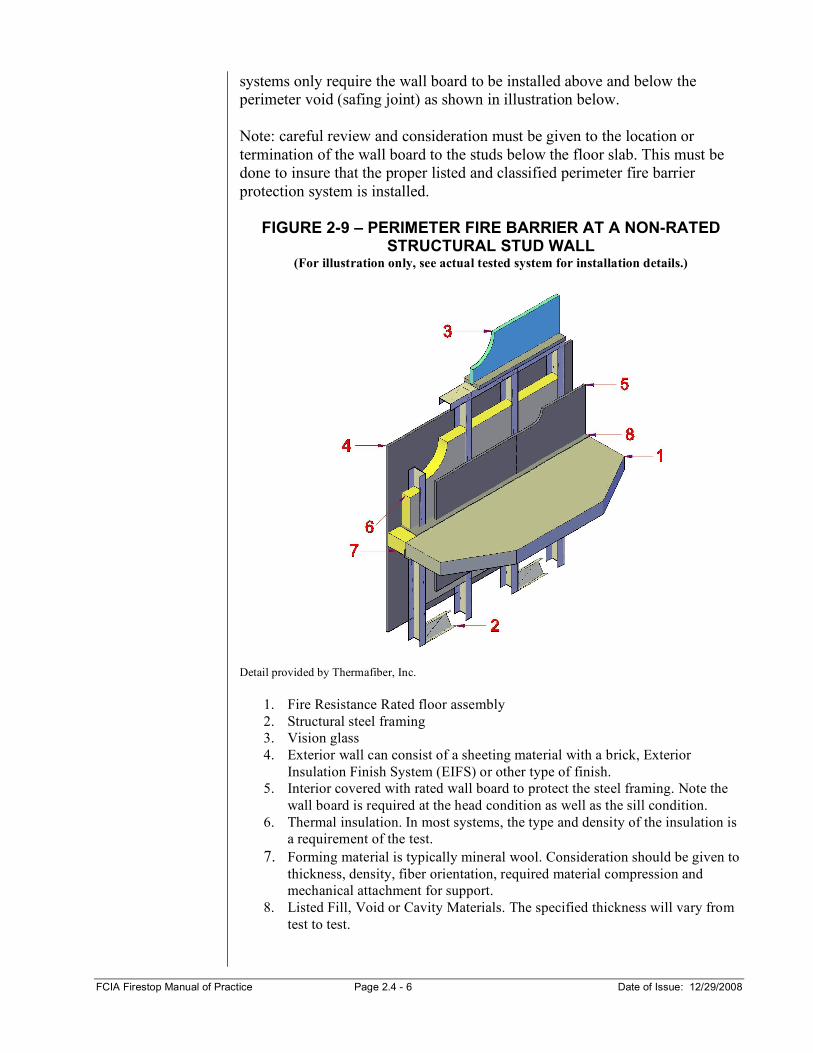
FIGURE 2-9 – PERIMETER FIRE BARRIER AT A NON-RATED STRUCTURAL STUD WALL
(For illustration only, see actual tested system for installation details.)
Detail provided by Thermafiber, Inc.
1. Fire Resistance Rated floor assembly 2. Structural steel framing 3. Vision glass 4. Exterior wall can consist of a sheeting material with a brick, Exterior
Insulation Finish System (EIFS) or other type of finish. 5. Interior covered with rated wall board to protect the steel framing. Note the
wall board is required at the head condition as well as the sill condition. 6. Thermal insulation. In most systems, the type and density of the insulation is
a requirement of the test. 7. Forming material is typically mineral wool. Consideration should be given to
thickness, density, fiber orientation, required material compression and mechanical attachment for support.
8. Listed Fill, Void or Cavity Materials. The specified thickness will vary from test to test.
FCIA Firestop Manual of Practice Page 2.4 - 7 Date of Issue: 12/29/2008
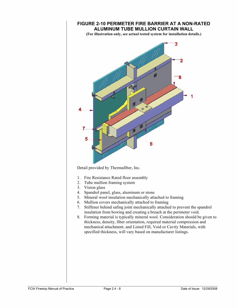
Figure 2-10 provides a perspective view of a building perimeter joint at a non-rated aluminum tube mullion curtain wall tested using the ASTM E2307 Intermediate-Scale, Multistory Test Apparatus. Aluminum curtain wall systems can support a variety of exterior glazing, glass, aluminum panels or stone, but they all have one thing in common: the aluminum framing members require a protection system in the spandrel area to protect the aluminum framing during a fire. As aluminum has a very low melting point, perimeter fire barrier systems have been developed to protect the aluminum framing supporting the fire barrier system. Perimeter Fire Barrier systems also may provide thermal insulation, vapor and sound control plus environmental protection. Installation is a very important aspect to these perimeter fire barrier systems. Additionally, it is recommended that all aluminum curtain wall systems have a built-in gutter system to drain condensation out of the wall system. The insulation should be held off the interior face of the glazing (a minimum of 1”), to prevent blocking of the drainage path for condensation. There is also one other very important consideration in this type of assembly. There is an issue if the insulation is placed in direct contact with the spandrel glass in the curtain wall system, it may void the warranty on the spandrel glass. Contact spandrel glass manufacturer for verification. Aluminum curtain wall framing systems are used throughout the world for exterior wall systems. There are two basic types of aluminum curtain wall framing systems.
1. Tube Mullion 2. Structural/I-Mullion
Typically, the curtain wall insulation is required to be mechanically attached per a classified and listed perimeter fire barrier system.
Non-Rated Aluminum Tube Mullion Curtain
Wall
FCIA Firestop Manual of Practice Page 2.4 - 8 Date of Issue: 12/29/2008
FIGURE 2-10 PERIMETER FIRE BARRIER AT A NON-RATED ALUMINUM TUBE MULLION CURTAIN WALL
(For illustration only, see actual tested system for installation details.)
Detail provided by Thermafiber, Inc. 1. Fire Resistance Rated floor assembly 2. Tube mullion framing system 3. Vision glass 4. Spandrel panel, glass, aluminum or stone 5. Mineral wool insulation mechanically attached to framing 6. Mullion covers mechanically attached to framing 7. Stiffener behind safing joint mechanically attached to prevent the spandrel
insulation from bowing and creating a breach at the perimeter void. 8. Forming material is typically mineral wool. Consideration should be given to
thickness, density, fiber orientation, required material compression and mechanical attachment, and Listed Fill, Void or Cavity Materials, with specified thickness, will vary based on manufacturer listings.

FCIA Firestop Manual of Practice Page 2.4 - 9 Date of Issue: 12/29/2008
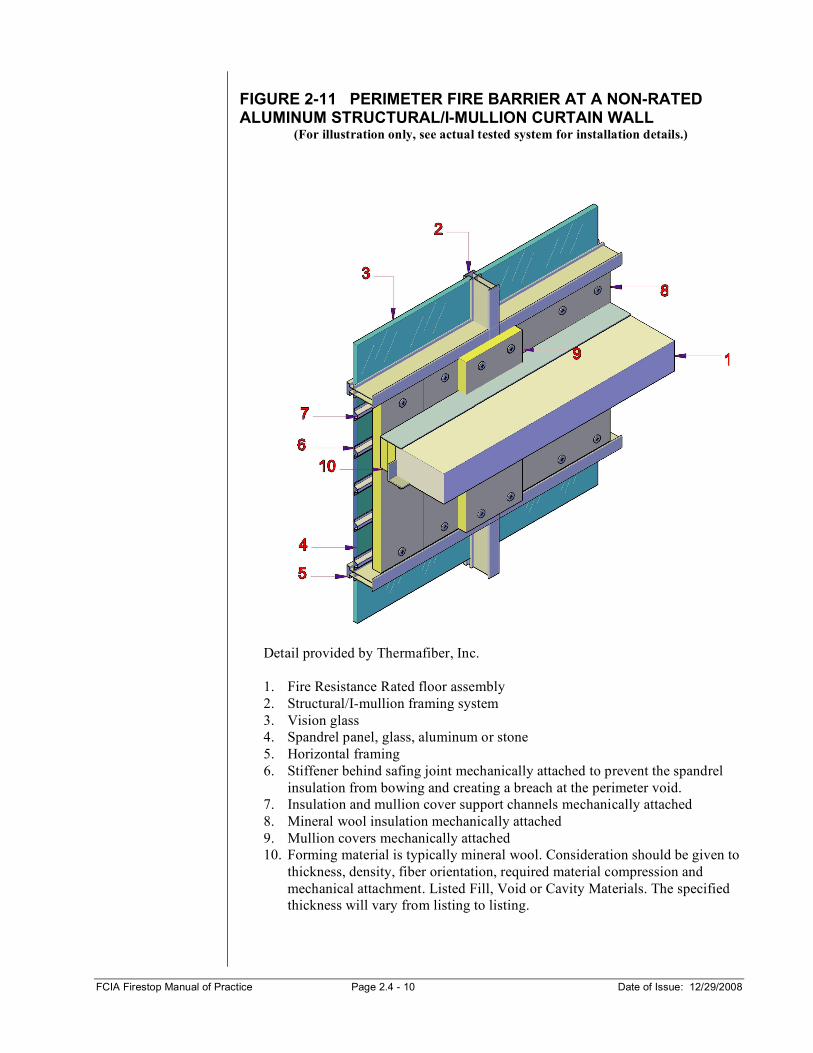
Figure 2-11 provides a perspective view of a building perimeter joint at a non-rated aluminum structural/I-mullion curtain wall tested using the ASTM E2307 Intermediate-Scale, Multistory Test Apparatus. All issues discussed in the above described tube mullion system apply to structural/I-mullion systems as well. The main difference with structural/I-mullion systems is the type of framing and interior finish system used. With this type of system there are no built in framing members at the head and sill condition to attach the insulation support system. The interior finish system is provided with a snap on cover. As can be seen from the drawing below, depending on the depth of the mullion and specified thickness of the insulation, it could leave a large void between the exterior wall and the insulation. This can be addressed using a thicker insulation or a fill strip of insulation at the head and sill if allowed by the test. These systems also are more challenging to install a properly sealed vapor retarder due to the limited surface area for attachment.
Non-Rated Aluminum
Structural/I-Mullion Curtain Wall
FCIA Firestop Manual of Practice Page 2.4 - 10 Date of Issue: 12/29/2008
FIGURE 2-11 PERIMETER FIRE BARRIER AT A NON-RATED ALUMINUM STRUCTURAL/I-MULLION CURTAIN WALL
(For illustration only, see actual tested system for installation details.)
Detail provided by Thermafiber, Inc. 1. Fire Resistance Rated floor assembly 2. Structural/I-mullion framing system 3. Vision glass 4. Spandrel panel, glass, aluminum or stone 5. Horizontal framing 6. Stiffener behind safing joint mechanically attached to prevent the spandrel
insulation from bowing and creating a breach at the perimeter void. 7. Insulation and mullion cover support channels mechanically attached 8. Mineral wool insulation mechanically attached 9. Mullion covers mechanically attached 10. Forming material is typically mineral wool. Consideration should be given to
thickness, density, fiber orientation, required material compression and mechanical attachment. Listed Fill, Void or Cavity Materials. The specified thickness will vary from listing to listing.
FCIA Firestop Manual of Practice Page 2.4 - 11 Date of Issue: 12/29/2008
Fire resistance Ratings for perimeter fire containment systems include an integrity rating, insulation rating, and a leakage rating. The testing is conducted per the ASTM E 2307-04 Standard Test Method for Determining Fire Resistance of Perimeter Fire Barriers Using Intermediate-Scale, Multi Story Test Apparatus. The ‘F’, or Flame rating, is an important part of penetration and joint firestop testing. The rating establishes the time the perimeter fire barrier system kept flames from penetrating through the interior slot area in the assembly. The ‘F’ rating is a key part of keeping effective compartmentation, effective, by preventing flame spread through the assembly…containing fire to the area rather than allowing vertical spread in case of perimeter fire barriers. Underwriters Laboratories (UL) is one of many laboratories that test perimeter fire barrier systems configurations for manufacturers to determine suitability for use of products in specific applications. There are two ratings as a result of a UL curtain wall fire test. The Integrity Rating is much like the “F” rating used for through-penetration firestop systems, in that no flame has passed from the lower floor (fire exposed area) to the interior of the upper floor (unexposed side of the floor), either through the gap or through the exterior wall assembly. The ASTM E 2307 standard defines testing of materials for suitability for use of the products in systems for the interior fire spread resistance through the F-Rating. Although manufacturers have tested and listed systems for the ‘leapfrog’ effect of fire at the perimeter where extension of fire may ‘lap’ outside the building from floor to the next floor, there is not an ASTM standard for addressing this condition. The Insulation Rating, which is similar to the “T” rating for through-penetration systems, requires resistance to flame propagation, but also limits the temperature rise of the Perimeter Fire Barrier System to a maximum rise of 325° F above the starting temperature on the interior surface of the curtainwall. Ratings are stated in hours, 1, 2, 3 or 4 hours. UL has a separate numbering system for perimeter fire containment systems. The Leakage (“L”) Rating is a measure of the amount of air leakage, in cubic feet per minute per square foot of opening area through the perimeter fire containment system at ambient and 400F. The “L” rating is intended to help authorities having jurisdiction and others in determining the suitability of perimeter fire containment systems for restricting the movement of smoke. There are two options for movement of the perimeter fire barrier systems, either static or dynamic. The dynamic test method includes movement capabilities, similar to those of other expansion and control joint systems. Class I has minimum 500 cycles, 1 cycle per minute, while II has 500 minimum cycles, 10 cycles per minute, and III 100 minimum cycles, 30 cycles per minute. The movement capabilities simulate movement from thermal, structural, seismic and wind loading of the assembly. Static systems do not allow for movement. See UL’s XHDG Guide info on the web or in the
Ratings
‘F’ Rating
Integrity Rating
Insulation Rating
FCIA Firestop Manual of Practice Page 2.4 - 12 Date of Issue: 12/29/2008
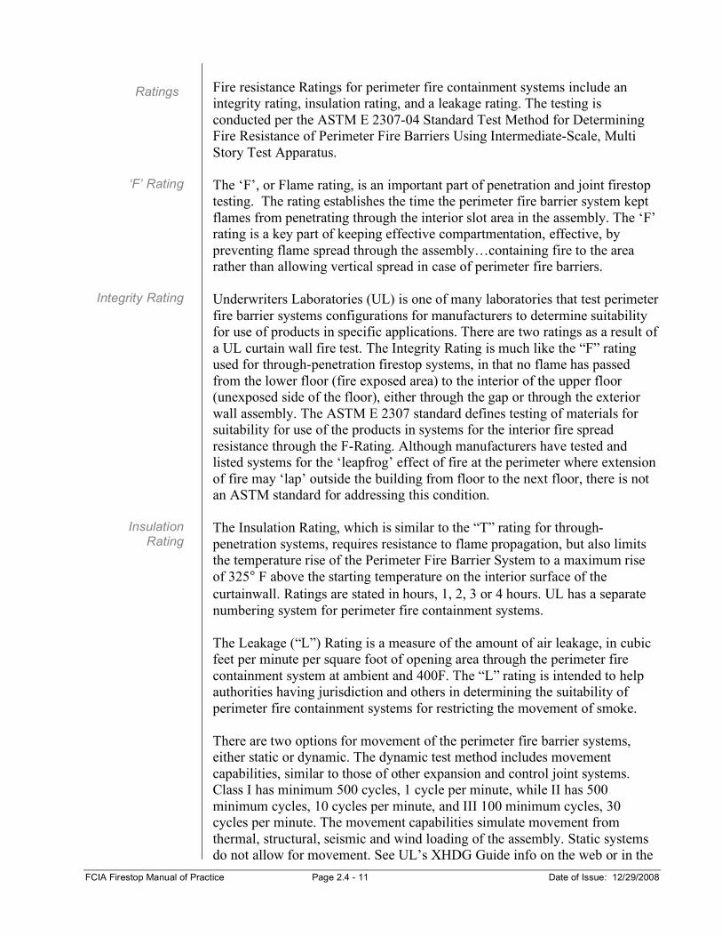
UL Fire Resistance Directory for further information about perimeter fire containment system testing.
Perimeter fire containment systems have clips holding mineral wool in place, And a fill, void or cavity material applied for complete assembly protection. Photos courtesy of Superl, Inc.
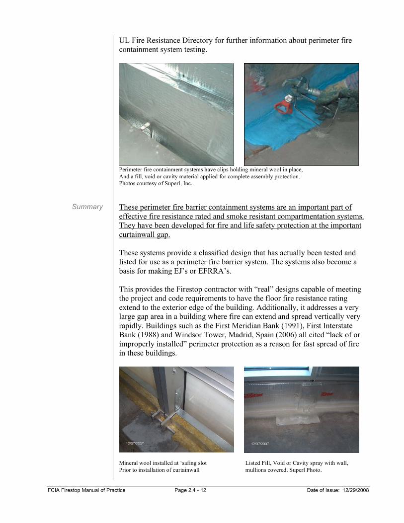
These perimeter fire barrier containment systems are an important part of effective fire resistance rated and smoke resistant compartmentation systems. They have been developed for fire and life safety protection at the important curtainwall gap. These systems provide a classified design that has actually been tested and listed for use as a perimeter fire barrier system. The systems also become a basis for making EJ’s or EFRRA’s. This provides the Firestop contractor with “real” designs capable of meeting the project and code requirements to have the floor fire resistance rating extend to the exterior edge of the building. Additionally, it addresses a very large gap area in a building where fire can extend and spread vertically very rapidly. Buildings such as the First Meridian Bank (1991), First Interstate Bank (1988) and Windsor Tower, Madrid, Spain (2006) all cited “lack of or improperly installed” perimeter protection as a reason for fast spread of fire in these buildings.
Mineral wool installed at ‘safing slot Listed Fill, Void or Cavity spray with wall, Prior to installation of curtainwall mullions covered. Superl Photo.
Summary