Embed Size (px)
Citation preview
23rd ASEMEP National Technical Symposium
1
UNDERSTANDING AND ELIMINATING WIRE BONDABILITY PROBLEM ON OVERHANG STACKED DIE
Bryan Christian S. Bacquian
Jefferson S. Talledo John Alexander L. Soriano
Corporate Packaging & Automation
STMicroelectronics, Inc., Calamba City, Laguna, Philippines [email protected], [email protected], [email protected]
ABSTRACT
Semiconductor industries, nowadays, have been aggressive in developing products that will cater for much more functionality. Overhang dies are introduced to accommodate multi-functionality but unfortunately will cause some critical problems due to complexity of the vertical structure of the IC package. Development of overhang dies offers challenges in terms of design and manufacturing. Understanding such challenges has been discussed in this paper.
In this study, an integrated approach involving mechanical modeling, package design and wire bonding optimization to eliminate wire bondability problem on overhang stacked die would be presented. The design of the die structure has been negotiated to have a stacked top die which has an overhang of 1.18mm die to die edge. Top die now acts as a cantilever plate in which wire bondability problem is commonly encountered. The design was analyzed using mechanical modeling and simulation (modal analysis and stress analysis) to determine critical pad locations and avoid vibration resonance as well as die crack during wire bonding. In order to verify modeling observation and quantify occurrence of NSOP (Non-Stick On Pad), actual evaluation matrix was also generated involving two different die structure samples with increasing impact bond force setting.
1.0 INTRODUCTION
Overhang stacked die application is the most difficult vertical die structure in package development. The top die acts like a cantilever plate that encounters static deflection or large amplitude vibration that defines the quality of the wire bonding process. Die deflection depends on the length of the overhang and the position of the bonding pad. The challenges encountered in package development is the definition of the range of impact force setting which will give good wire bondability and avoid the occurrence of die crack that might happen on the top stacked die near the edge of the bottom die. Evaluation has been performed to cover the matrix of impact force vs. die structure and measured
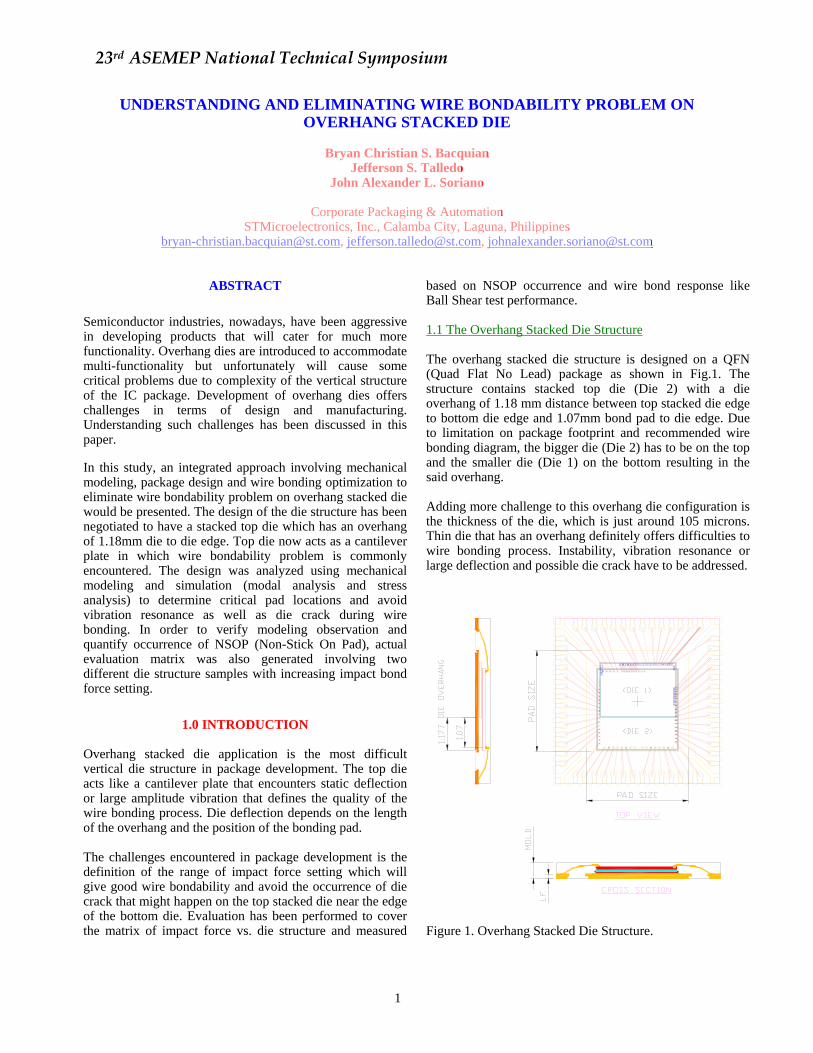
based on NSOP occurrence and wire bond response like Ball Shear test performance. 1.1 The Overhang Stacked Die Structure The overhang stacked die structure is designed on a QFN (Quad Flat No Lead) package as shown in Fig.1. The structure contains stacked top die (Die 2) with a die overhang of 1.18 mm distance between top stacked die edge to bottom die edge and 1.07mm bond pad to die edge. Due to limitation on package footprint and recommended wire bonding diagram, the bigger die (Die 2) has to be on the top and the smaller die (Die 1) on the bottom resulting in the said overhang. Adding more challenge to this overhang die configuration is the thickness of the die, which is just around 105 microns. Thin die that has an overhang definitely offers difficulties to wire bonding process. Instability, vibration resonance or large deflection and possible die crack have to be addressed.
V 3V3D
V3 V3 D
V1 V8 D
VSS
VSS
VSS
VSSVSS
VSS
V3 V3 D V 1V8DGPI O7G PI O3 V1 V2 CORE V1 V2 COREV1 V2 CORE
T M< 3>
T M< 2>
T M< 1>
T M< 0>
VPP
GPI O0 _ SA
GPI O1 _ SA
AF E_ S CLK_SA
AF E_ RST _SA
GPI O1 _A GPI O0 _AAF E_ FR _RDYAF E_ RST AFE_ SCS AFE_ SDA0AFE_ SCL K AF E_ SDA1 MSDA T SDAMSCL T SCL I NTBG PI O1 RST BGPI O2 G PI O0
DEBUG
GPI O4
GPI O5
GPI O6
V1 V2 D
Figure 1. Overhang Stacked Die Structure.
23rd ASEMEP National Technical Symposium
2
1.2 Deflection and Die Stress In overhang applications, deflection of the die is the most critical output response to be checked during structural design. However, if the existing design will now be fixed, specific study should be conducted to analyze the amount of deflection. In engineering, deflection is being described as the displacement of a structural element under load, which can be referred as angle or distance. The distance of the member is directly proportional to the amount of energy being applied towards the load. Thus, deflection of the top overhang die can be measured by the amount of top overhang length and position of bonding pad versus bonding force applied on the corner of the top overhang die. Contact force is the most important bonding parameter to be checked during die deflection study. In wire bond cycle, contact force is the first contact parameter being applied and will be used as the reference for bonding height, which makes it critical. If the die surface is not as stable just like on an overhang application, maximum contact force should be determined to have good wire bondability and acceptable die stress that would not result in die crack.
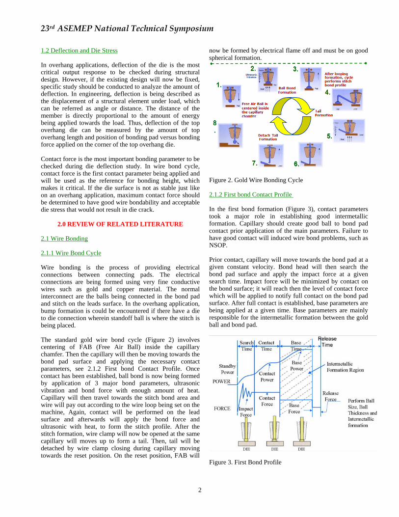
2.0 REVIEW OF RELATED LITERATURE 2.1 Wire Bonding 2.1.1 Wire Bond Cycle Wire bonding is the process of providing electrical connections between connecting pads. The electrical connections are being formed using very fine conductive wires such as gold and copper material. The normal interconnect are the balls being connected in the bond pad and stitch on the leads surface. In the overhang application, bump formation is could be encountered if there have a die to die connection wherein standoff ball is where the stitch is being placed. The standard gold wire bond cycle (Figure 2) involves centering of FAB (Free Air Ball) inside the capillary chamfer. Then the capillary will then be moving towards the bond pad surface and applying the necessary contact parameters, see 2.1.2 First bond Contact Profile. Once contact has been established, ball bond is now being formed by application of 3 major bond parameters, ultrasonic vibration and bond force with enough amount of heat. Capillary will then travel towards the stitch bond area and wire will pay out according to the wire loop being set on the machine, Again, contact will be performed on the lead surface and afterwards will apply the bond force and ultrasonic with heat, to form the stitch profile. After the stitch formation, wire clamp will now be opened at the same capillary will moves up to form a tail. Then, tail will be detached by wire clamp closing during capillary moving towards the reset position. On the reset position, FAB will
now be formed by electrical flame off and must be on good spherical formation.
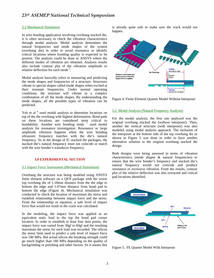
Figure 2. Gold Wire Bonding Cycle 2.1.2 First bond Contact Profile In the first bond formation (Figure 3), contact parameters took a major role in establishing good intermetallic formation. Capillary should create good ball to bond pad contact prior application of the main parameters. Failure to have good contact will induced wire bond problems, such as NSOP. Prior contact, capillary will move towards the bond pad at a given constant velocity. Bond head will then search the bond pad surface and apply the impact force at a given search time. Impact force will be minimized by contact on the bond surface; it will reach then the level of contact force which will be applied to notify full contact on the bond pad surface. After full contact is established, base parameters are being applied at a given time. Base parameters are mainly responsible for the intermetallic formation between the gold ball and bond pad.
Figure 3. First Bond Profile
23rd ASEMEP National Technical Symposium
3
2.2 Mechanical Simulation In wire bonding application involving overhang stacked die, it is often necessary to check the vibration characteristics through modal analysis. Modal analysis determines the natural frequencies and mode shapes of the system (overhang die) in order to avoid resonance or identify critical locations where bonding quality is expected to be poorest. The analysis could be done in ANSYS where the different modes of vibration are obtained. Analysis results also include contour plot of the vibration amplitude or relative deflection for each mode 5. Modal analysis basically refers to measuring and predicting the mode shapes and frequencies of a structure. Structures vibrate in special shapes called mode shapes when excited at their resonant frequencies. Under normal operating conditions, the structure will vibrate in a complex combination of all the mode shapes. By understanding the mode shapes, all the possible types of vibration can be predicted. Yeh et al 6 used modal analysis to determine locations on top of the die overhang with highest deformation. Bond pads on these locations are considered most critical to bondability. Another wire bonding study 7 used modal analysis for resonance investigation. Resonance or large amplitude vibration happens when the wire bonding ultrasonic frequency matches with the die’s natural frequency. So in the design of IC stacked die packages, the stacked die’s natural frequency must not coincide or match with the wire bonder’s transducer frequency.
3.0 EXPERIMENTAL SECTION
3.1 Impact Force Assessment (Mechanical Simulation) Overhang die structure was being modeled using ANSYS finite element software on a QFN package with the worse top overhang die of 1.18mm distance from the die edge to bottom die edge and 1.07mm distance from bond pad to bottom die edge (Figure 4). Mechanical simulation was conducted to check the location of maximum die stress and establish relationship between impact force and die stress. From the relationship or equation, a safe level of impact force that would not result in die crack was calculated. In the modeling, the impact force was applied as an equivalent static load to the top die bond pad corner location. In order to establish at least four data points, the impact force was varied from 30gf to 60gf and the resulting maximum die stress for each load was recorded. The silicon die stress limit used to predict a safe level of impact force was 180 MPa. But actual silicon die breaking strength could go much higher than 180 MPa depending on the quality of backgrinding or polishing and other factors. So it means this
is already quite safe to make sure die crack would not happen.
Figure 4. Finite Element Quarter Model Without Interposer 3.2 Modal Analysis (Natural Frequency Analysis) For the modal analysis, the first one analyzed was the original overhang stacked die (without interposer). Then, another die vertical structure (with interposer) was also modeled using modal analysis approach. The inclusion of die interposer at the bottom side of the top overhang die as shown in Figure 5 was done in order to have another alternative solution to the original overhang stacked die design. Both designs were being assessed in terms of vibration characteristics (mode shapes & natural frequencies) to ensure that the wire bonder’s frequency and stacked die’s natural frequency would not coincide and produce resonance or excessive vibration. From the results, contour plot of the relative deflection was also extracted and critical pad locations identified.
Figure 5. FE Quarter Model With Interposer
23rd ASEMEP National Technical Symposium
4
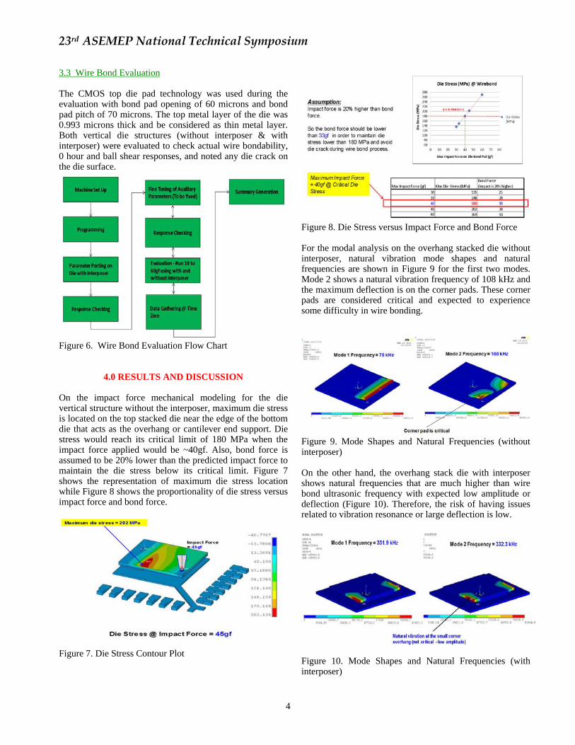
3.3 Wire Bond Evaluation The CMOS top die pad technology was used during the evaluation with bond pad opening of 60 microns and bond pad pitch of 70 microns. The top metal layer of the die was 0.993 microns thick and be considered as thin metal layer. Both vertical die structures (without interposer & with interposer) were evaluated to check actual wire bondability, 0 hour and ball shear responses, and noted any die crack on the die surface.
Figure 6. Wire Bond Evaluation Flow Chart
4.0 RESULTS AND DISCUSSION On the impact force mechanical modeling for the die vertical structure without the interposer, maximum die stress is located on the top stacked die near the edge of the bottom die that acts as the overhang or cantilever end support. Die stress would reach its critical limit of 180 MPa when the impact force applied would be ~40gf. Also, bond force is assumed to be 20% lower than the predicted impact force to maintain the die stress below its critical limit. Figure 7 shows the representation of maximum die stress location while Figure 8 shows the proportionality of die stress versus impact force and bond force.
Figure 7. Die Stress Contour Plot
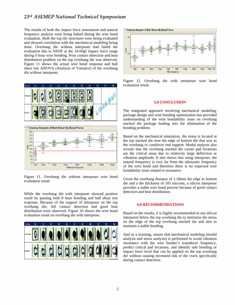
Figure 8. Die Stress versus Impact Force and Bond Force For the modal analysis on the overhang stacked die without interposer, natural vibration mode shapes and natural frequencies are shown in Figure 9 for the first two modes. Mode 2 shows a natural vibration frequency of 108 kHz and the maximum deflection is on the corner pads. These corner pads are considered critical and expected to experience some difficulty in wire bonding.
Figure 9. Mode Shapes and Natural Frequencies (without interposer) On the other hand, the overhang stack die with interposer shows natural frequencies that are much higher than wire bond ultrasonic frequency with expected low amplitude or deflection (Figure 10). Therefore, the risk of having issues related to vibration resonance or large deflection is low.
Figure 10. Mode Shapes and Natural Frequencies (with interposer)
23rd ASEMEP National Technical Symposium
5
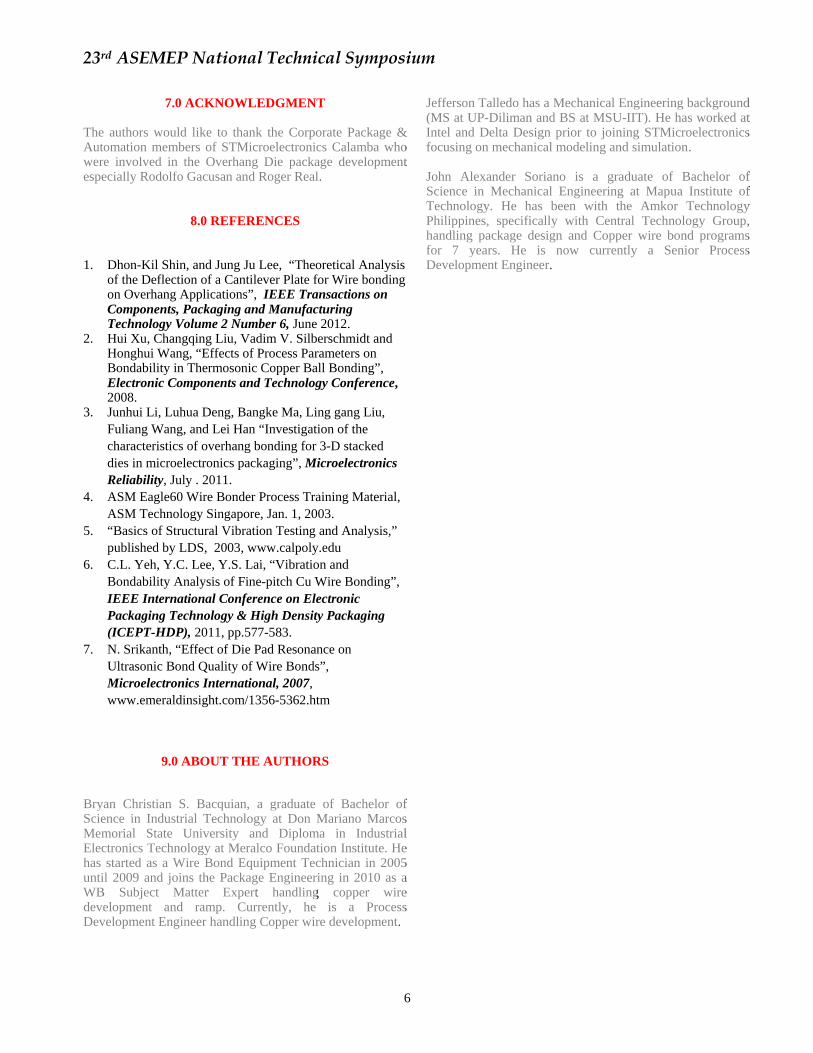
The results of both the impact force assessment and natural frequency analysis were being linked during the wire bond evaluation. Both the top die structures were being evaluated and showed correlation with the mechanical modeling being done. Overhang die without interposer had failed the evaluation due to NSOP at the 10-60gf impact force range during 0 hour wire bonding. Poor contact detection and heat distribution problem on the top overhang die was observed. Figure 11 shows the actual wire bond response and ball shear test ANOVA (Analysis of Variance) of the overhang die without interposer.
Figure 11. Overhang die without interposer wire bond evaluation result While the overhang die with interposer showed positive result by passing both 0 hour bonding and ball shear test response. Because of the support of interposer on the top overhang die, full contact detection and good heat distribution were observed. Figure 10 shows the wire bond evaluation result on overhang die with interposer.
Figure 12. Overhang die with interposer wire bond evaluation result.
5.0 CONCLUSION The integrated approach involving mechanical modeling, package design and wire bonding optimization has provided understanding of the wire bondability issue on overhang stacked die package leading into the elimination of the bonding problem. Based on the mechanical simulation, die stress is located at the top stacked die near the edge of bottom die that acts as the overhang or cantilever end support. Modal analysis also reveals that the overhang stacked die corner pad locations are the critical areas due to relatively large deflection or vibration amplitude. It also shows that using interposer, the natural frequency is very far from the ultrasonic frequency of the wire bond and therefore there is no expected wire bondability issue related to resonance. Given the overhang distance of 1.18mm die edge to bottom die and a die thickness of 105 microns, a silicon interposer provides a stable wire bond process because of good contact detection and heat distribution.
6.0 RECOMMENDATIONS Based on the results, it is highly recommended to use silicon interposer below the top overhang die to minimize die stress on the edge of the top overhang stacked die and also to maintain a stable bonding. And as a learning, ensure that mechanical modeling (modal analysis and stress analysis) is performed to avoid vibration resonance with the wire bonder’s transducer frequency, predict critical pad locations, and identify safe bonding or impact force level that can be applied on the top overhang die without causing increased risk of die crack specifically during contact detection.
23rd ASEMEP National Technical Symposium
6
7.0 ACKNOWLEDGMENT
The authors would like to thank the Corporate Package & Automation members of STMicroelectronics Calamba who were involved in the Overhang Die package development especially Rodolfo Gacusan and Roger Real.
8.0 REFERENCES
1. Dhon-Kil Shin, and Jung Ju Lee, “Theoretical Analysis of the Deflection of a Cantilever Plate for Wire bonding on Overhang Applications”, IEEE Transactions on Components, Packaging and Manufacturing Technology Volume 2 Number 6, June 2012.
2. Hui Xu, Changqing Liu, Vadim V. Silberschmidt and Honghui Wang, “Effects of Process Parameters on Bondability in Thermosonic Copper Ball Bonding”, Electronic Components and Technology Conference, 2008.
3. Junhui Li, Luhua Deng, Bangke Ma, Ling gang Liu, Fuliang Wang, and Lei Han “Investigation of the characteristics of overhang bonding for 3-D stacked dies in microelectronics packaging”, Microelectronics Reliability, July . 2011.
4. ASM Eagle60 Wire Bonder Process Training Material, ASM Technology Singapore, Jan. 1, 2003.
5. “Basics of Structural Vibration Testing and Analysis,” published by LDS, 2003, www.calpoly.edu
6. C.L. Yeh, Y.C. Lee, Y.S. Lai, “Vibration and Bondability Analysis of Fine-pitch Cu Wire Bonding”, IEEE International Conference on Electronic Packaging Technology & High Density Packaging (ICEPT-HDP), 2011, pp.577-583.
7. N. Srikanth, “Effect of Die Pad Resonance on Ultrasonic Bond Quality of Wire Bonds”, Microelectronics International, 2007, www.emeraldinsight.com/1356-5362.htm
9.0 ABOUT THE AUTHORS
Bryan Christian S. Bacquian, a graduate of Bachelor of Science in Industrial Technology at Don Mariano Marcos Memorial State University and Diploma in Industrial Electronics Technology at Meralco Foundation Institute. He has started as a Wire Bond Equipment Technician in 2005 until 2009 and joins the Package Engineering in 2010 as a WB Subject Matter Expert handling copper wire development and ramp. Currently, he is a Process Development Engineer handling Copper wire development.
Jefferson Talledo has a Mechanical Engineering background (MS at UP-Diliman and BS at MSU-IIT). He has worked at Intel and Delta Design prior to joining STMicroelectronics focusing on mechanical modeling and simulation. John Alexander Soriano is a graduate of Bachelor of Science in Mechanical Engineering at Mapua Institute of Technology. He has been with the Amkor Technology Philippines, specifically with Central Technology Group, handling package design and Copper wire bond programs for 7 years. He is now currently a Senior Process Development Engineer.