Embed Size (px)
Citation preview
237
FIBERSENSORS
LASERSENSORS
PHOTOELECTRICSENSORS
MICROPHOTOELECTRIC
SENSORS
AREASENSORS
SAFETY LIGHT CURTAINS /
SAFETY COMPONENTSPRESSURE /
FLOWSENSORS
INDUCTIVEPROXIMITY
SENSORS
PARTICULARUSE SENSORS
SENSOROPTIONS
SIMPLEWIRE-SAVING
UNITS
WIRE-SAVING SYSTEMS
MEASUREMENTSENSORS
STATIC CONTROL DEVICES
LASERMARKERS
PLC
HUMAN MACHINE INTERFACES
ENERGY MANAGEMENT
SOLUTIONS
FA COMPONENTS
MACHINE VISION SYSTEMS
UV CURING SYSTEMS
Selection Guide
Amplifier Built-in
Power Supply Built-in
Amplifier-separated
EX-Z
CX-400
CY-100
EX-10
EX-20
EX-30
EX-40
CX-440
EQ-30
EQ-500
MQ-W
RX-LS200
RX
RT-610
Related Information
PNP outputtype available
Unit volume ratio reduced by about 50%* * As compared to EX-10 series
The world’s thinnest* sensor dimension of 3 mm 0.118 in has been achieved by utilizing new semiconductor packaging technology that does not use wire bonding. The small unit size allows installation of sensors in a narrow space where only a conventional fiber sensor head could be installed before. The built-in amplifier also saves on installation space.* Among photoelectric sensors with built-in amplifier, as of April 2017 in-company survey
Ultra-minute Photoelectric Sensor Amplifier Built-in
EX-Z SERIES
The World’s No. 1* in Compactness * Among photoelectric sensors with built-in amplifier, as of April 2017 in-company survey
■ General terms and conditions ............. F-3 ■Selection guide ............................. P.231~
■ Glossary of terms........................ P.1549~ ■General precautions…………… . P.1552~
panasonic.net/id/pidsx/global
Front sensing type Side sensing type
Approx.
50% smallerin volume ratio
than EX-10
Approx.
35% smallerin volume ratio
than EX-10
EX-Z1□F□W8 × H14 × D3 mmW0.315 × H0.551 × D0.118 in
EX-Z1□W5.5 × H15.9 × D6.5 mmW0.217 × H0.626 × D0.256 in
Recognition
Ultra-minute Photoelectric Sensor EX-Z SERIES 238
FIBERSENSORS
LASERSENSORS
PHOTOELECTRICSENSORS
MICROPHOTOELECTRICSENSORS
AREASENSORS
SAFETY LIGHT CURTAINS /SAFETY COMPONENTSPRESSURE / FLOWSENSORSINDUCTIVEPROXIMITYSENSORS
PARTICULARUSE SENSORS
SENSOROPTIONS
SIMPLEWIRE-SAVINGUNITS
WIRE-SAVING SYSTEMS
MEASUREMENTSENSORS
STATIC CONTROL DEVICES
LASERMARKERS
PLC
HUMAN MACHINE INTERFACES
ENERGY MANAGEMENT SOLUTIONS
FA COMPONENTS
MACHINE VISION SYSTEMS
UV CURING SYSTEMS
Selection GuideAmplifier Built-inPower Supply Built-inAmplifier-separated
EX-Z
CX-400
CY-100
EX-10
EX-20
EX-30
EX-40
CX-440
EQ-30
EQ-500
MQ-W
RX-LS200
RX
RT-610
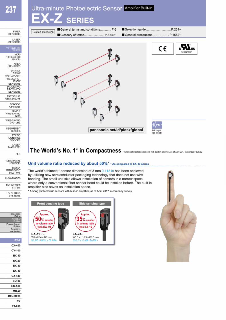
APPLICATIONS
Detection of parts in parts feeder
Detection of presence / absence of test tube tray
Detection of LED lead
Bending-resistant cable type available for all modelsBending-resistant cable type with improved flex resistance is available for all models. Select the model suitable for your specific application.The standard type comes with lead wires with the same diameter as previous models, but the outside diameter of the cable is 2.0 mm 0.079 in and thinner than the cables of the EX-10 series. This facilitates cable routing.
ENVIRONMENTAL RESISTANCE
Waterproof IP67The sensors features an IP67 rating to allow their use in process lines where water is used or splashed.Rust-resistant stainless steel sensor mounting brackets and screws are available.Note: If water splashes on the sensor during sensing operation, it may
sense water as an object.
Capable of sensing an extremely small ø0.3 mm ø0.012 in object without slitA slit is provided on the front side of the main sensor body. The sensor can detect a ø0.3 mm ø0.012 in object (the smallest-object sensing capability in the industry*) without using an optional slit.* Among photoelectric sensors with built-in amplifier, as of April 2017
in-company survey
EX-Z11□Capability to sense a small ø1.0 mm ø0.039 in object over long distanceThe high-brightness 4-element red LED provides strong light emission stably over a long period of time. In spite of the extremely small size, both front sensing and side sensing units can sense a small ø1.0 mm ø0.039 in object from a long distance of 500 mm 19.685 in. Since the spotlight is clearly visible, the sensing position can be easily confirmed.
EX-Z13□
Built-in slitEX-Z11□Slit diameter: 0.3 mm 0.012 in
Sensing of end of thin pipe
Clearly visible
spotlight
IP67(IEC)
239 Ultra-minute Photoelectric Sensor EX-Z SERIES
FIBERSENSORS
LASERSENSORS
PHOTO-ELECTRICSENSORS
MICROPHOTO-
ELECTRICSENSORS
AREASENSORS
SAFETY LIGHT CURTAINS /
SAFETY COMPONENTSPRESSURE /
FLOWSENSORS
INDUCTIVEPROXIMITY
SENSORS
PARTICULARUSE
SENSORS
SENSOROPTIONS
SIMPLEWIRE-SAVING
UNITS
WIRE-SAVING SYSTEMS
MEASURE-MENT
SENSORS
STATIC CONTROL DEVICES
LASERMARKERS
PLC
HUMAN MACHINE
INTERFACES
ENERGY MANAGEMENT
SOLUTIONS
FA COMPONENTS
MACHINE VISION
SYSTEMS
UV CURING
SYSTEMS
Selection Guide
Amplifier Built-in
Power Supply Built-in
Amplifier-separated
EX-Z
CX-400
CY-100
EX-10
EX-20
EX-30
EX-40
CX-440
EQ-30
EQ-500
MQ-W
RX-LS200
RX
RT-610
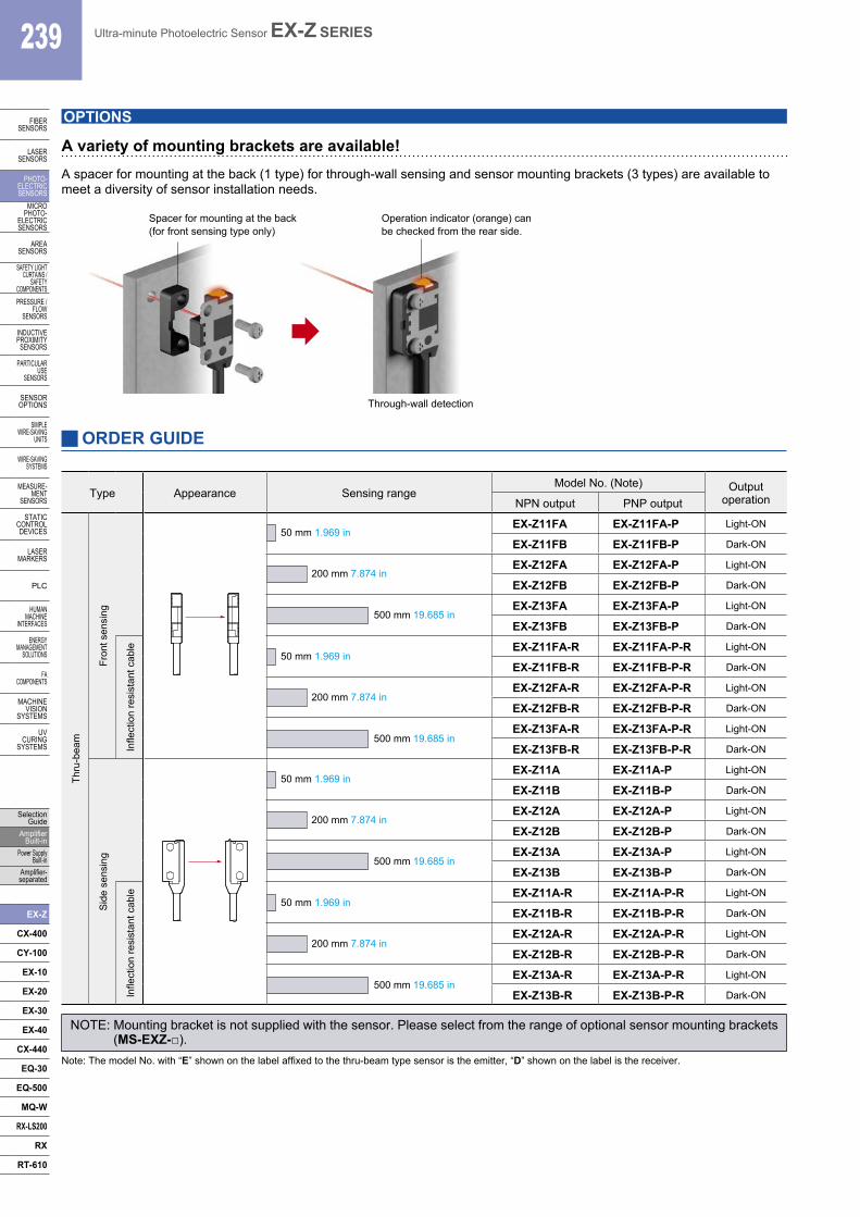
ORDER GUIDE
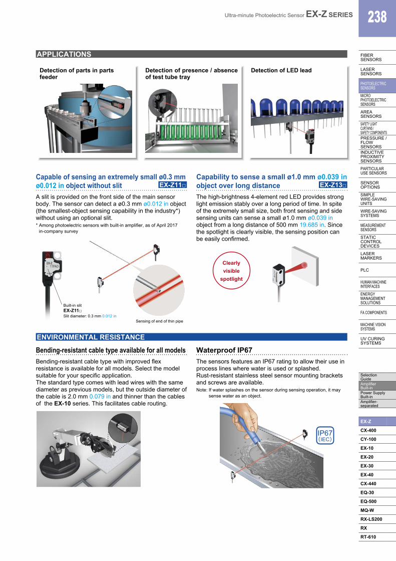
A variety of mounting brackets are available!A spacer for mounting at the back (1 type) for through-wall sensing and sensor mounting brackets (3 types) are available to meet a diversity of sensor installation needs.
OPTIONS
Spacer for mounting at the back(for front sensing type only)
Operation indicator (orange) can be checked from the rear side.
Through-wall detection
Type Appearance Sensing rangeModel No. (Note) Output
operationNPN output PNP output
Thru
-bea
m
Fron
t sen
sing
EX-Z11FA EX-Z11FA-P Light-ON
EX-Z11FB EX-Z11FB-P Dark-ON
EX-Z12FA EX-Z12FA-P Light-ON
EX-Z12FB EX-Z12FB-P Dark-ON
EX-Z13FA EX-Z13FA-P Light-ON
EX-Z13FB EX-Z13FB-P Dark-ON
Infle
ctio
n re
sist
ant c
able EX-Z11FA-R EX-Z11FA-P-R Light-ON
EX-Z11FB-R EX-Z11FB-P-R Dark-ON
EX-Z12FA-R EX-Z12FA-P-R Light-ON
EX-Z12FB-R EX-Z12FB-P-R Dark-ON
EX-Z13FA-R EX-Z13FA-P-R Light-ON
EX-Z13FB-R EX-Z13FB-P-R Dark-ON
Sid
e se
nsin
g
EX-Z11A EX-Z11A-P Light-ON
EX-Z11B EX-Z11B-P Dark-ON
EX-Z12A EX-Z12A-P Light-ON
EX-Z12B EX-Z12B-P Dark-ON
EX-Z13A EX-Z13A-P Light-ON
EX-Z13B EX-Z13B-P Dark-ON
Infle
ctio
n re
sist
ant c
able EX-Z11A-R EX-Z11A-P-R Light-ON
EX-Z11B-R EX-Z11B-P-R Dark-ON
EX-Z12A-R EX-Z12A-P-R Light-ON
EX-Z12B-R EX-Z12B-P-R Dark-ON
EX-Z13A-R EX-Z13A-P-R Light-ON
EX-Z13B-R EX-Z13B-P-R Dark-ON
NOTE: Mounting bracket is not supplied with the sensor. Please select from the range of optional sensor mounting brackets (MS-EXZ-□).
Note: The model No. with “E” shown on the label affixed to the thru-beam type sensor is the emitter, “D” shown on the label is the receiver.
50 mm 1.969 in
200 mm 7.874 in
500 mm 19.685 in
50 mm 1.969 in
200 mm 7.874 in
500 mm 19.685 in
50 mm 1.969 in
200 mm 7.874 in
500 mm 19.685 in
50 mm 1.969 in
200 mm 7.874 in
500 mm 19.685 in
Ultra-minute Photoelectric Sensor EX-Z SERIES 240
FIBERSENSORS
LASERSENSORS
PHOTO-ELECTRICSENSORSMICROPHOTO-ELECTRICSENSORS
AREASENSORS
SAFETY LIGHT CURTAINS /SAFETY COMPONENTSPRESSURE / FLOWSENSORS
INDUCTIVEPROXIMITYSENSORS
PARTICULARUSE SENSORS
SENSOROPTIONS
SIMPLEWIRE-SAVINGUNITS
WIRE-SAVING SYSTEMS
MEASURE-MENTSENSORS
STATIC CONTROL DEVICES
LASERMARKERS
PLC
HUMAN MACHINE INTERFACES
ENERGY MANAGEMENT SOLUTIONS
FA COMPONENTS
MACHINE VISION SYSTEMS
UV CURING SYSTEMS
Selection GuideAmplifier Built-inPower Supply Built-inAmplifier-separated
EX-Z
CX-400
CY-100
EX-10
EX-20
EX-30
EX-40
CX-440
EQ-30
EQ-500
MQ-W
RX-LS200
RX
RT-610
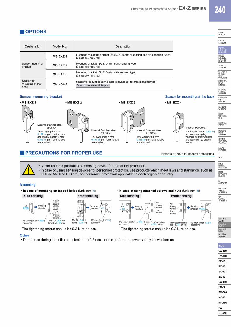
Designation Model No. Description
Sensor mounting bracket
MS-EXZ-1 L-shaped mounting bracket (SUS304) for front sensing and side sensing types(2 sets are required)
MS-EXZ-2 Mounting bracket (SUS304) for front sensing type(2 sets are required)
MS-EXZ-3 Mounting bracket (SUS304) for side sensing type(2 sets are required)
Spacer for mounting at the back
MS-EXZ-4Spacer for mounting at the back (polyacetal) for front sensing typeOne set consists of 10 pcs.
Sensor mounting bracket
OPTIONS
• MS-EXZ-1
Material: Stainless steel (SUS304)
Two M2 (length 4 mm 0.157 in) pan head screws and two M2 (length 8 mm 0.315 in) pan head screws are attached.
Material: Stainless steel (SUS304)
Two M2 (length 4 mm 0.157 in) pan head screws are attached.
Material: Stainless steel (SUS304)
Two M2 (length 8 mm 0.315 in) pan head screws are attached.
Material: PolyacetalM2 (length: 10 mm 0.394 in) screws, nuts, spring washers and flat washers are attached. (20 pieces each)
• MS-EXZ-2 • MS-EXZ-3 • MS-EXZ-4
Spacer for mounting at the back
PRECAUTIONS FOR PROPER USE
• Never use this product as a sensing device for personnel protection.• In case of using sensing devices for personnel protection, use products which meet laws and standards, such as
OSHA, ANSI or IEC etc., for personnel protection applicable in each region or country.
Mounting• In case of mounting on tapped holes (Unit: mm in)
The tightening torque should be 0.2 N·m or less.
• In case of using attached screws and nuts (Unit: mm in)
The tightening torque should be 0.2 N·m or less.
Side sensing Front sensing Side sensing Front sensing
M2 screw (length 10 0.394) (accessory)
M2 × 0.4 0.016 hole tapped, 5 0.197 deep
8.50.335
Sensing direction
8.50.335
Sensing direction
M2 × 0.4 0.016 hole tapped, 7 0.276 deep
M2 screw (length 6 0.236) (accessory)
8.50.335
Sensing direction
M2 screw (length 10 0.394) (accessory)
Thickness of mounting plate: 2 0.079 or less
NutSpring washerFlat washer
8.50.335
Sensing direction
Thickness of mounting plate: 2 0.079 or less
M2 screw (length 6 0.236) (accessory)
NutSpring washerFlat washer
Other• Do not use during the initial transient time (0.5 sec. approx.) after the power supply is switched on.
Refer to p.1552~ for general precautions.
241 Ultra-minute Photoelectric Sensor EX-Z SERIES
FIBERSENSORS
LASERSENSORS
PHOTO-ELECTRICSENSORS
MICROPHOTO-
ELECTRICSENSORS
AREASENSORS
SAFETY LIGHT CURTAINS /
SAFETY COMPONENTSPRESSURE /
FLOWSENSORS
INDUCTIVEPROXIMITY
SENSORS
PARTICULARUSE
SENSORS
SENSOROPTIONS
SIMPLEWIRE-SAVING
UNITS
WIRE-SAVING SYSTEMS
MEASURE-MENT
SENSORS
STATIC CONTROL DEVICES
LASERMARKERS
PLC
HUMAN MACHINE
INTERFACES
ENERGY MANAGEMENT
SOLUTIONS
FA COMPONENTS
MACHINE VISION
SYSTEMS
UV CURING
SYSTEMS
Selection Guide
Amplifier Built-in
Power Supply Built-in
Amplifier-separated
EX-Z
CX-400
CY-100
EX-10
EX-20
EX-30
EX-40
CX-440
EQ-30
EQ-500
MQ-W
RX-LS200
RX
RT-610
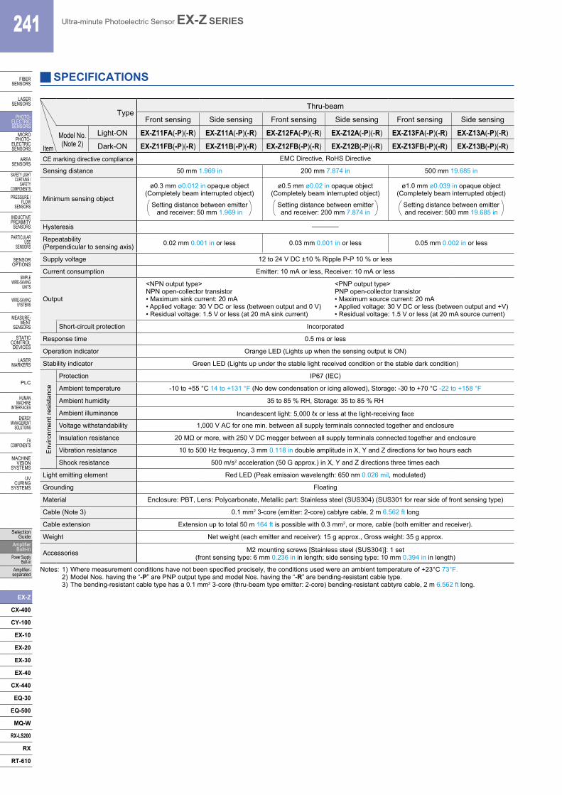
SPECIFICATIONS
TypeThru-beam
Front sensing Side sensing Front sensing Side sensing Front sensing Side sensing
Model No.(Note 2)
Light-ON EX-Z11FA(-P)(-R) EX-Z11A(-P)(-R) EX-Z12FA(-P)(-R) EX-Z12A(-P)(-R) EX-Z13FA(-P)(-R) EX-Z13A(-P)(-R)
Item Dark-ON EX-Z11FB(-P)(-R) EX-Z11B(-P)(-R) EX-Z12FB(-P)(-R) EX-Z12B(-P)(-R) EX-Z13FB(-P)(-R) EX-Z13B(-P)(-R)CE marking directive compliance EMC Directive, RoHS Directive
Sensing distance 50 mm 1.969 in 200 mm 7.874 in 500 mm 19.685 in
Minimum sensing object
ø0.3 mm ø0.012 in opaque object(Completely beam interrupted object)
Setting distance between emitter and receiver: 50 mm 1.969 in
ø0.5 mm ø0.02 in opaque object(Completely beam interrupted object)
Setting distance between emitter and receiver: 200 mm 7.874 in
ø1.0 mm ø0.039 in opaque object(Completely beam interrupted object)
Setting distance between emitter and receiver: 500 mm 19.685 in
Hysteresis –
Repeatability (Perpendicular to sensing axis) 0.02 mm 0.001 in or less 0.03 mm 0.001 in or less 0.05 mm 0.002 in or less
Supply voltage 12 to 24 V DC ±10 % Ripple P-P 10 % or less
Current consumption Emitter: 10 mA or less, Receiver: 10 mA or less
Output
<NPN output type> NPN open-collector transistor• Maximum sink current: 20 mA• Applied voltage: 30 V DC or less (between output and 0 V)• Residual voltage: 1.5 V or less (at 20 mA sink current)
<PNP output type>PNP open-collector transistor• Maximum source current: 20 mA• Applied voltage: 30 V DC or less (between output and +V)• Residual voltage: 1.5 V or less (at 20 mA source current)
Short-circuit protection Incorporated
Response time 0.5 ms or less
Operation indicator Orange LED (Lights up when the sensing output is ON)
Stability indicator Green LED (Lights up under the stable light received condition or the stable dark condition)
Env
ironm
ent r
esis
tanc
e
Protection IP67 (IEC)
Ambient temperature -10 to +55 °C 14 to +131 °F (No dew condensation or icing allowed), Storage: -30 to +70 °C -22 to +158 °F
Ambient humidity 35 to 85 % RH, Storage: 35 to 85 % RH
Ambient illuminance Incandescent light: 5,000 ℓx or less at the light-receiving face
Voltage withstandability 1,000 V AC for one min. between all supply terminals connected together and enclosure
Insulation resistance 20 MΩ or more, with 250 V DC megger between all supply terminals connected together and enclosure
Vibration resistance 10 to 500 Hz frequency, 3 mm 0.118 in double amplitude in X, Y and Z directions for two hours each
Shock resistance 500 m/s2 acceleration (50 G approx.) in X, Y and Z directions three times each
Light emitting element Red LED (Peak emission wavelength: 650 nm 0.026 mil, modulated)
Grounding Floating
Material Enclosure: PBT, Lens: Polycarbonate, Metallic part: Stainless steel (SUS304) (SUS301 for rear side of front sensing type)
Cable (Note 3) 0.1 mm2 3-core (emitter: 2-core) cabtyre cable, 2 m 6.562 ft long
Cable extension Extension up to total 50 m 164 ft is possible with 0.3 mm2, or more, cable (both emitter and receiver).
Weight Net weight (each emitter and receiver): 15 g approx., Gross weight: 35 g approx.
Accessories M2 mounting screws [Stainless steel (SUS304)]: 1 set (front sensing type: 6 mm 0.236 in in length; side sensing type: 10 mm 0.394 in in length)
Notes: 1) Where measurement conditions have not been specified precisely, the conditions used were an ambient temperature of +23°C 73°F. 2) Model Nos. having the “-P” are PNP output type and model Nos. having the “-R” are bending-resistant cable type. 3) The bending-resistant cable type has a 0.1 mm2 3-core (thru-beam type emitter: 2-core) bending-resistant cabtyre cable, 2 m 6.562 ft long.
Ultra-minute Photoelectric Sensor EX-Z SERIES 242
FIBERSENSORS
LASERSENSORS
PHOTO-ELECTRICSENSORSMICROPHOTO-ELECTRICSENSORS
AREASENSORS
SAFETY LIGHT CURTAINS /SAFETY COMPONENTSPRESSURE / FLOWSENSORS
INDUCTIVEPROXIMITYSENSORS
PARTICULARUSE SENSORS
SENSOROPTIONS
SIMPLEWIRE-SAVINGUNITS
WIRE-SAVING SYSTEMS
MEASURE-MENTSENSORS
STATIC CONTROL DEVICES
LASERMARKERS
PLC
HUMAN MACHINE INTERFACES
ENERGY MANAGEMENT SOLUTIONS
FA COMPONENTS
MACHINE VISION SYSTEMS
UV CURING SYSTEMS
Selection GuideAmplifier Built-inPower Supply Built-inAmplifier-separated
EX-Z
CX-400
CY-100
EX-10
EX-20
EX-30
EX-40
CX-440
EQ-30
EQ-500
MQ-W
RX-LS200
RX
RT-610
20 10 0 10 200
20
40
60
80
0.787
1.575
2.362
3.150
100 50 0 50 1000.787 0.394 0.394 0.787
0
20
40
60
80
0.787
1.575
2.362
3.150
Operating position ℓ (mm in)CenterLeft Right CenterLeft Right
Operating angle θ (°)
Receiver
Emitter
L
ℓ Set
ting
dist
ance
L (m
m in
)
Set
ting
dist
ance
L (m
m in
)
Receiver Emitter
θL
100 50 0 50 1003.937 1.969 1.969 3.937
0
100
200
100 50 0 50 1000
100
200
3.937
7.874
3.937
7.874
Operating position ℓ (mm in)CenterLeft Right CenterLeft Right
Operating angle θ (°)
Receiver Emitter
L
ℓ
Receiver Emitter
θL
Set
ting
dist
ance
L (m
m in
)
Set
ting
dist
ance
L (m
m in
)
100 50 0 50 1003.937 1.969 1.969 3.937
0
400
800
100 50 0 50 1000
400
800
200
600
15.748
31.496
7.874
23.622
200
600
15.748
31.496
7.874
23.622
Set
ting
dist
ance
L (m
m in
)
Set
ting
dist
ance
L (m
m in
)
CenterLeft RightOperating angle θ (°)Operating position ℓ (mm in)
CenterLeft Right
Receiver Emitter
L
ℓReceiver
Emitter
θL
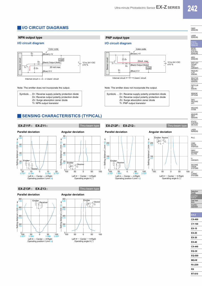
SENSING CHARACTERISTICS (TYPICAL)
EX-Z11F□ EX-Z11□ Thru-beam type
Parallel deviation
Parallel deviation
Parallel deviation Angular deviation
Angular deviation
Angular deviation
I/O CIRCUIT DIAGRAMS
NPN output type
I/O circuit diagram
PNP output type
I/O circuit diagram
Users’ circuitInternal circuit
20 mA max.Tr
D1
ZD
(Blue) 0 V
+
−12 to 24 V DC±10 %
Sen
sor c
ircui
t
(Brown) +V
(Black) Output (Note)
Color code
LoadD2
Note: The emitter does not incorporate the output.
Symbols … D1: Reverse supply polarity protection diode D2: Reverse output polarity protection diode ZD: Surge absorption zener diode Tr: NPN output transistor
Users’ circuitInternal circuit
D1
20mA max.ZD
Tr(Black) Output (Note)
(Blue) 0 V
12 to 24 V DC±10 %
+
−
(Brown) +V
Load
Color code
D2
Sen
sor c
ircui
t
Note: The emitter does not incorporate the output.
Symbols … D1: Reverse supply polarity protection diode D2: Reverse output polarity protection diode ZD: Surge absorption zener diode Tr: PNP output transistor
EX-Z12F□ EX-Z12□ Thru-beam type
EX-Z13F□ EX-Z13□ Thru-beam type
243 Ultra-minute Photoelectric Sensor EX-Z SERIES
FIBERSENSORS
LASERSENSORS
PHOTO-ELECTRICSENSORS
MICROPHOTO-
ELECTRICSENSORS
AREASENSORS
SAFETY LIGHT CURTAINS /
SAFETY COMPONENTSPRESSURE /
FLOWSENSORS
INDUCTIVEPROXIMITY
SENSORS
PARTICULARUSE
SENSORS
SENSOROPTIONS
SIMPLEWIRE-SAVING
UNITS
WIRE-SAVING SYSTEMS
MEASURE-MENT
SENSORS
STATIC CONTROL DEVICES
LASERMARKERS
PLC
HUMAN MACHINE
INTERFACES
ENERGY MANAGEMENT
SOLUTIONS
FA COMPONENTS
MACHINE VISION
SYSTEMS
UV CURING
SYSTEMS
Selection Guide
Amplifier Built-in
Power Supply Built-in
Amplifier-separated
EX-Z
CX-400
CY-100
EX-10
EX-20
EX-30
EX-40
CX-440
EQ-30
EQ-500
MQ-W
RX-LS200
RX
RT-610
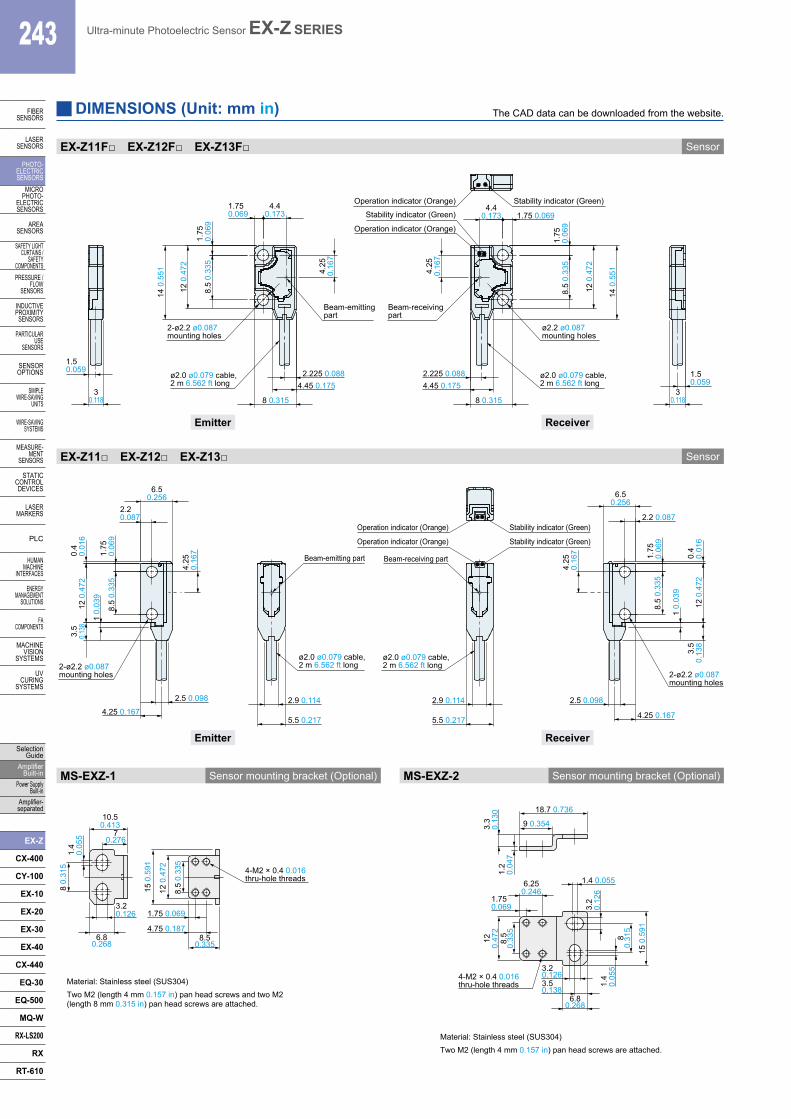
EX-Z11F□ EX-Z12F□ EX-Z13F□ Sensor
EX-Z11□ EX-Z12□ EX-Z13□ Sensor
DIMENSIONS (Unit: mm in) The CAD data can be downloaded from the website.
1.5 0.059
30.118
Beam-emitting part
ø2.0 ø0.079 cable, 2 m 6.562 ft long
ø2.0 ø0.079 cable, 2 m 6.562 ft long
Operation indicator (Orange)
Beam-receiving part
Stability indicator (Green) 1.75 0.069
4.25
0.16
7
8 0.315
4.45 0.1752.225 0.088
8.5
0.33
5
14 0
.551
4.40.173
4.25
0.16
7
4.40.173
1.75 0.069
1.75
0.06
9
12 0
.472
14 0
.551
8.5
0.33
5
4.45 0.1752.225 0.088
8 0.315
12 0
.472
1.75
0.
069
Operation indicator (Orange) Stability indicator (Green)
1.5 0.059
30.118
2-ø2.2 ø0.087 mounting holes
ø2.2 ø0.087 mounting holes
2.9 0.114 2.9 0.114
1 0.
039
2.5 0.098
4.25
0.16
7
2.5 0.098
1 0.
039
4.25
0.16
7
ø2.0 ø0.079 cable, 2 m 6.562 ft long
Beam-emitting part
5.5 0.217
Stability indicator (Green)
ø2.0 ø0.079 cable, 2 m 6.562 ft long
Beam-receiving part
Operation indicator (Orange)
5.5 0.217
2-ø2.2 ø0.087mounting holes
8.5
0.33
5
4.25 0.167
12 0
.472
1.75
0.06
9
2.2 0.087
6.50.256
3.5
0.13
80.
40.
016
Operation indicator (Orange) Stability indicator (Green)
2-ø2.2 ø0.087mounting holes
2.20.087
6.50.256
12 0
.472
4.25 0.167
1.75
0.06
98.
5 0.
335
3.5
0.138
0.4
0.01
6
ReceiverEmitter
ReceiverEmitter
MS-EXZ-1 Sensor mounting bracket (Optional)
Material: Stainless steel (SUS304)Two M2 (length 4 mm 0.157 in) pan head screws and two M2 (length 8 mm 0.315 in) pan head screws are attached.
MS-EXZ-2 Sensor mounting bracket (Optional)
Material: Stainless steel (SUS304) Two M2 (length 4 mm 0.157 in) pan head screws are attached.
1.4
0.05
5 70.276
10.50.413
15 0
.591
12 0
.472
8.5
0.33
5
8 0.
315
3.20.126
6.80.268
8.50.335
4.75 0.187
1.75 0.069
4-M2 × 0.4 0.016 thru-hole threads
1.2
0.04
7
3.3
0.13
0
9 0.354
18.7 0.736
15 0
.591
80.
315
3.2
0.12
61.
40.
055
8.5
0.33
5
120.
472
3.50.138
6.250.246
6.80.268
3.20.126
1.750.069
1.4 0.055
4-M2 × 0.4 0.016 thru-hole threads
Ultra-minute Photoelectric Sensor EX-Z SERIES 244
FIBERSENSORS
LASERSENSORS
PHOTO-ELECTRICSENSORSMICROPHOTO-ELECTRICSENSORS
AREASENSORS
SAFETY LIGHT CURTAINS /SAFETY COMPONENTSPRESSURE / FLOWSENSORS
INDUCTIVEPROXIMITYSENSORS
PARTICULARUSE SENSORS
SENSOROPTIONS
SIMPLEWIRE-SAVINGUNITS
WIRE-SAVING SYSTEMS
MEASURE-MENTSENSORS
STATIC CONTROL DEVICES
LASERMARKERS
PLC
HUMAN MACHINE INTERFACES
ENERGY MANAGEMENT SOLUTIONS
FA COMPONENTS
MACHINE VISION SYSTEMS
UV CURING SYSTEMS
Selection GuideAmplifier Built-inPower Supply Built-inAmplifier-separated
EX-Z
CX-400
CY-100
EX-10
EX-20
EX-30
EX-40
CX-440
EQ-30
EQ-500
MQ-W
RX-LS200
RX
RT-610
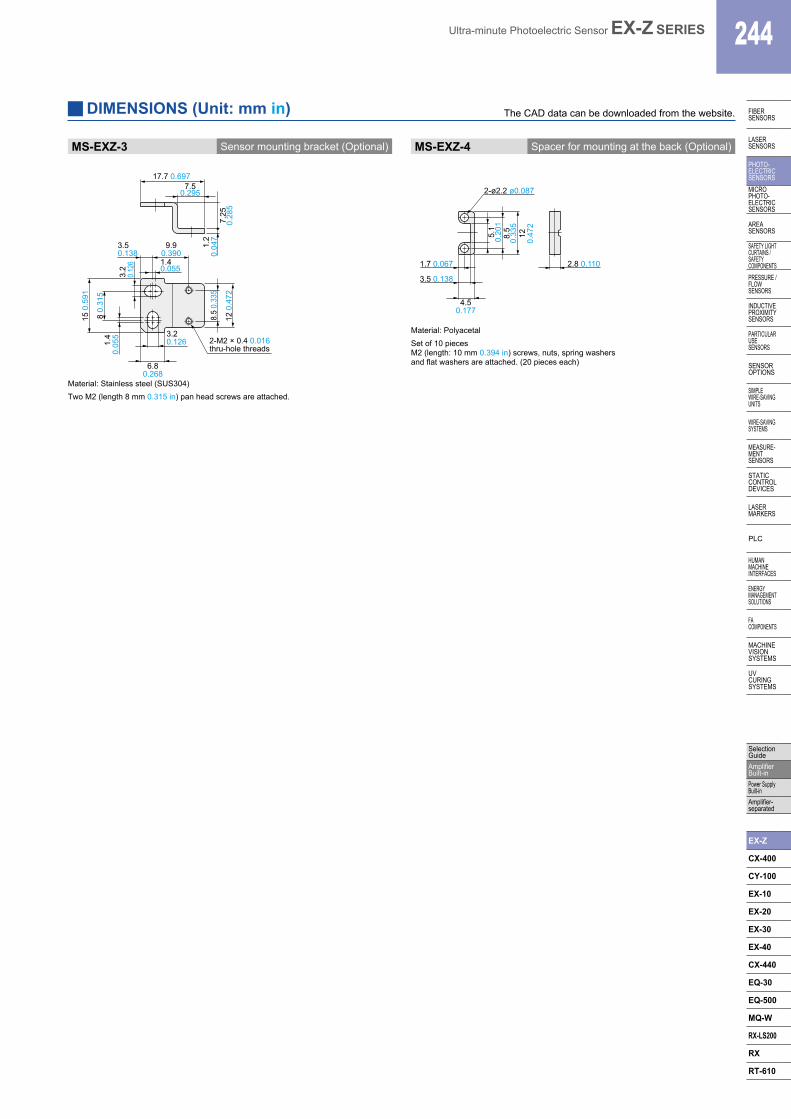
MS-EXZ-3 Sensor mounting bracket (Optional) MS-EXZ-4 Spacer for mounting at the back (Optional)
1.2
0.04
7
7.50.295
17.7 0.697
7.25
0.28
5
1.4
0.05
53.
20.
126
12 0
.472
8.5
0.33
5
8 0.
315
15 0
.591
3.20.126
1.40.055
6.80.268
9.90.390
3.50.138
2-M2 × 0.4 0.016 thru-hole threads
5.1
0.20
18.
50.
335
120.
472
4.50.177
2.8 0.110
3.5 0.138
1.7 0.067
2-ø2.2 ø0.087
Material: Stainless steel (SUS304)Two M2 (length 8 mm 0.315 in) pan head screws are attached.
Material: PolyacetalSet of 10 piecesM2 (length: 10 mm 0.394 in) screws, nuts, spring washers and flat washers are attached. (20 pieces each)
DIMENSIONS (Unit: mm in) The CAD data can be downloaded from the website.
![Digital Laser Sensor [Amplifier-separated] LS · PDF filepanasonic-electric-works.net/sunx ... Selection Guide Amplifier Built-in Amplifier-separated LS Digital fiber sensor FX-500/300](https://img.pdfslide.us/doc/110x75/5aacad2b7f8b9a8f498d55e8/digital-laser-sensor-amplifier-separated-ls-selection-guide-amplifier-built-in.jpg)
![Ultra-slim Photoelectric Sensor [Amplifier Built-in] EX-10 ... · Title: Ultra-slim Photoelectric Sensor [Amplifier Built-in] EX-10 SERIES Ver.2 Subject: General 2011-2012 Created](https://img.pdfslide.us/doc/110x75/60568f77f17dbd2ea05f58e6/ultra-slim-photoelectric-sensor-amplifier-built-in-ex-10-title-ultra-slim.jpg)
![Ultra-compact Laser Sensor [Amplifier Built-in] EX … and Brochures/ex-l200.pdfUltra-compact Laser Sensor Amplifier Built-in EX-L200 SERIES ... PNP output type available ... SPOT](https://img.pdfslide.us/doc/110x75/5aa8194e7f8b9aa2258b6a89/ultra-compact-laser-sensor-amplifier-built-in-ex-and-brochuresex-l200pdfultra-compact.jpg)