Embed Size (px)
Citation preview
����'28%/(�6/,'(�5$,/�56�6HULHV�����
SBH TIEFBAUTECHNIK GmbH, Ferdinand-Porsche-Str. 8, 52525 Heinsberg page 1
G:\123V5W\Verwendungsanleitungen\englisch\Verwendung-RS-750-eng 2008.doc 13.03.2009
23(5$7,1*�0$18$/�'28%/(�6/,'(�5$,/�56�6HULHV�����
Manufacturer: 6%+�7LHIEDXWHFKQLN�*PE+ Ferdinand-Porsche-Str. 8 � � D – 52525 HEINSBERG
Phone: +49 (0) 24 52 / 91 04 0 Fax: +49 (0) 24 52 / 91 04 50 E-mail: [email protected] Homepage: http:\ \ www.sbh-tiefbautechnik.com
����'28%/(�6/,'(�5$,/�56�6HULHV�����
SBH TIEFBAUTECHNIK GmbH, Ferdinand-Porsche-Str. 8, 52525 Heinsberg page 2
G:\123V5W\Verwendungsanleitungen\englisch\Verwendung-RS-750-eng 2008.doc 13.03.2009
&RQWHQWV�*HQHUDO�LQVWUXFWLRQV
Lifting & transporting 3
Measures to reduce danger 3
Maintenance & repair 3
7HFKQLFDO�GHVFULSWLRQ� ��4
6\VWHP�GUDZLQJV�Mini - RS 5
Standard - RS 6
Mega - RS 7
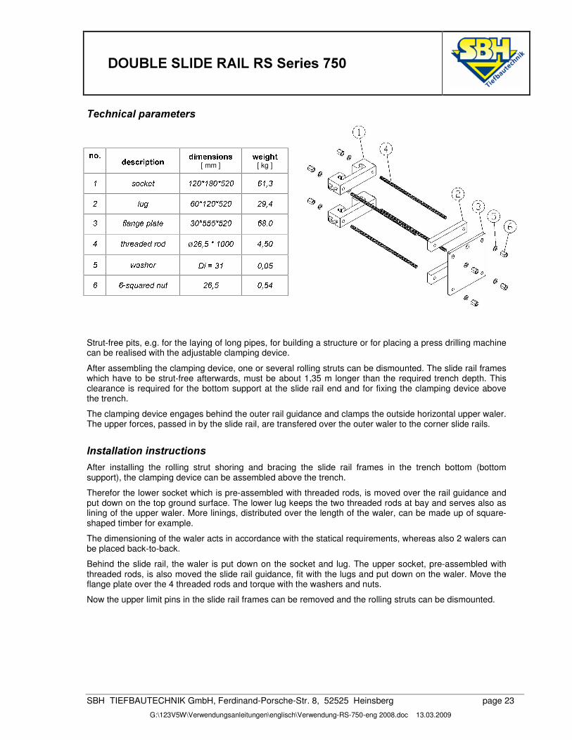
7HFKQLFDO�SDUDPHWHUV
Sshoring plates 8
Rolling struts (RS) and distance pieces 9
RS slide rail 10
Accessories 11
$VVHPEO\�LQVWUXFWLRQV� 12
Assembly help 14
Assembly of extension rail 14
,QVWDOODWLRQ�LQVWUXFWLRQV�
Allowed tensile forces 15
Alignment of the initial shoring bay 15
Installation of the extension rail 19
5H�,QVWDOODWLRQ� 20
%RWWRP�VXSSRUW� 21
$GMXVWDEOH�FODPSLQJ�GHYLFH�
System drawing 22
Technical parameters 23
Installation instructions 23
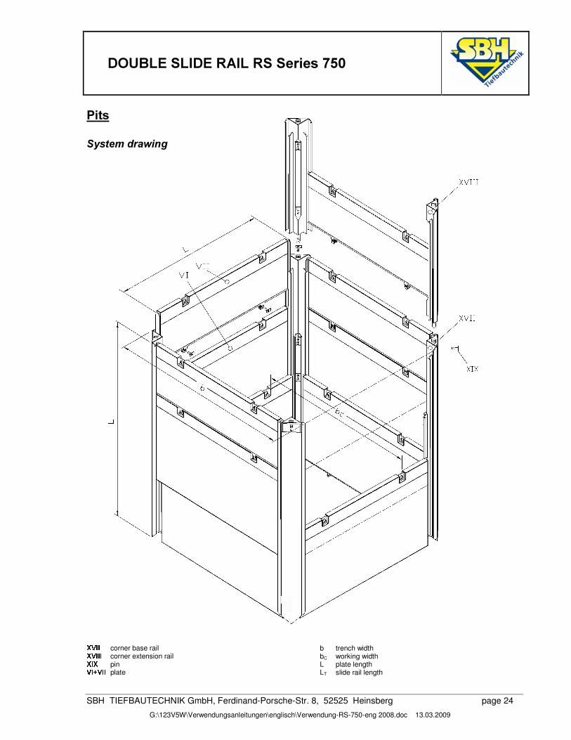
3LWV�
System drawing 24
Installation instructions 25
Installation of extension rails 27
����'28%/(�6/,'(�5$,/�56�6HULHV�����
SBH TIEFBAUTECHNIK GmbH, Ferdinand-Porsche-Str. 8, 52525 Heinsberg page 3
G:\123V5W\Verwendungsanleitungen\englisch\Verwendung-RS-750-eng 2008.doc 13.03.2009
*HQHUDO�LQVWUXFWLRQV�The shoring must be without gap and close to the ground. The limiting values for the max. loads have to be kept strictly. Single shoring sections (boxes) may only be used if the front and rear faces are properly secured.
The folllowing rules and regulations have to be followed in their valid version:
¾ Regulations of the BG-Fachausschuss Tiefbau (technical commitee civil and underground engineering)
¾ DIN 4124 Baugruben und Gräben (excavation pits and trenches)
¾ DIN EN 13331 Teil 1 & 2 Grabenverbaugeräte (part 1 & 2 construction equipment)
¾ Regeln für Sicherheit und Gesundheit bei der Arbeit (rules for safety and health during work)
¾ Unfallverhütungsvorschriften / Arbeitsschutzvorschriften (accident prevention and safety at work rules)
Our shoring components have the GS-Sign „Certified Safety“.
During installation the instructions of this operating manual have to be followed.
/LIWLQJ��7UDQVSRUWLQJ�¾ The shoring may only be attached at the corresponding eyes and openings and/or lifting accessories.
¾ The lifting accessories must be adapted to the weight which must be transported.
¾ For safety reasons only load hooks with hook safety must be used.
¾ The allowed tensile forces have to be kept in any case.
¾ The transporting has to be carried out next to the soil and unneeded pendulum movements have to be avoided.
¾ It is forbidden to enter the swivel range of the lifting tool and to stay under floating loads.
¾ It has to be paid attention to overhead contact lines.
¾ Engine driver and instructor must have face-to-face interaction.
0HDVXUHV�WR�UHGXFH�GDQJHU�¾ The construction site has to be sufficiently secured and marked.
¾ Neighbouring traffic flow has to be made possible by means of security personnel if needed.
¾ The personnel must wear protective clothing (helmet / safety shoes / gloves).
¾ Possible instabilities as a result of wind loads, during the assembly and installation, must be considered.
¾ The shoring components must be layed down – preferably in horizontal way – on a firm underground.
¾ In case of slopes it has to focus on a stable storage or mounting of pre-assembled components.
0DLQWHQDQFH��UHSDLU�¾ As a matter of principle, the operability of all shoring components must be checked before use.
¾ Defective or deformed components may not be used in any case.
¾ Slighter damages may be repaired by yourselves after consulting SBH. Otherwise, our service at SBH is at your disposal if desired.
¾ Only original spare parts of SBH may be used.
¾ According to intenseness of use, the components should be painted with anti-corrosive paint every 2 years.
����'28%/(�6/,'(�5$,/�56�6HULHV�����
SBH TIEFBAUTECHNIK GmbH, Ferdinand-Porsche-Str. 8, 52525 Heinsberg page 4
G:\123V5W\Verwendungsanleitungen\englisch\Verwendung-RS-750-eng 2008.doc 13.03.2009
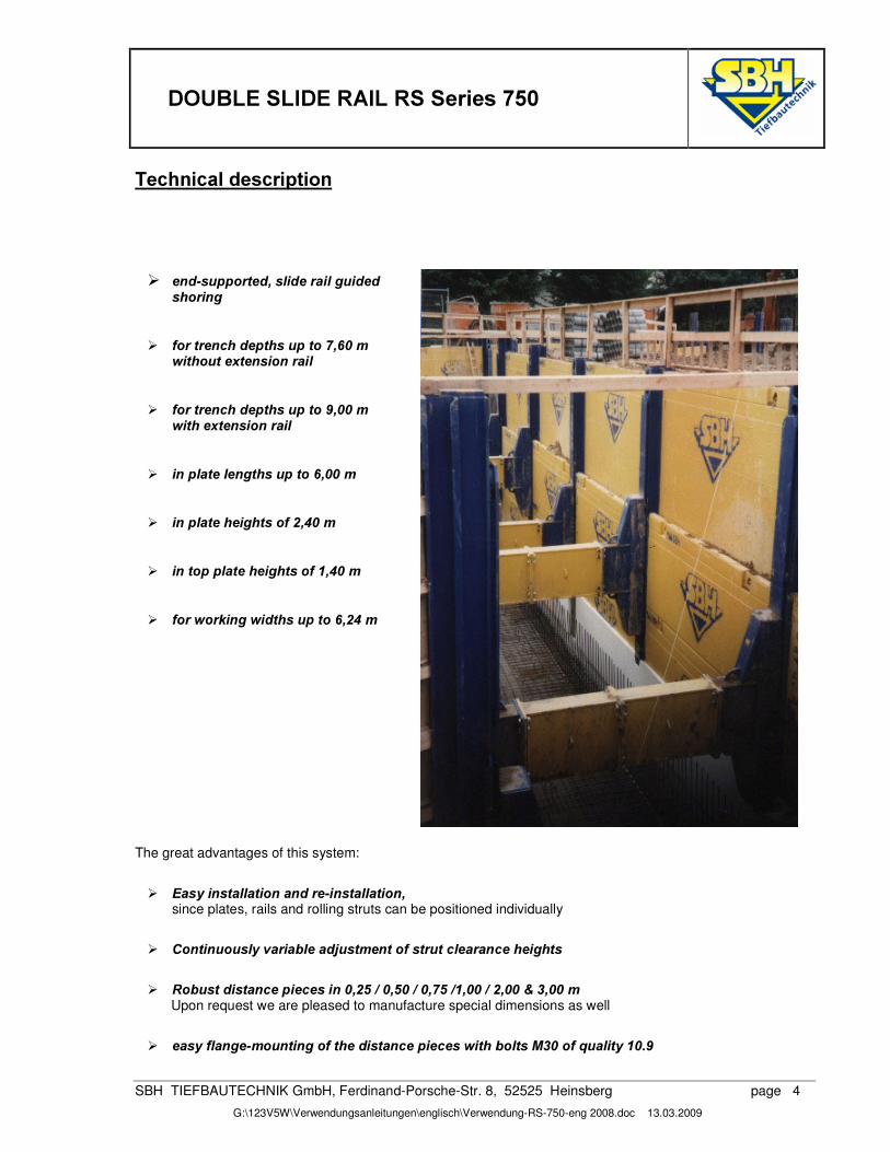
7HFKQLFDO�GHVFULSWLRQ�
¾ HQG�VXSSRUWHG��VOLGH�UDLO�JXLGHG�VKRULQJ�
¾ IRU�WUHQFK�GHSWKV�XS�WR������P�������ZLWKRXW�H[WHQVLRQ�UDLO�
¾ IRU�WUHQFK�GHSWKV�XS�WR������P����������ZLWK�H[WHQVLRQ�UDLO�
¾ LQ�SODWH�OHQJWKV�XS�WR������P�
¾ LQ�SODWH�KHLJKWV�RI������P�
¾ LQ�WRS�SODWH�KHLJKWV�RI������P�
¾ IRU�ZRUNLQJ�ZLGWKV�XS�WR������P�
The great advantages of this system:
¾ (DV\�LQVWDOODWLRQ�DQG�UH�LQVWDOODWLRQ�� since plates, rails and rolling struts can be positioned individually
¾ &RQWLQXRXVO\�YDULDEOH�DGMXVWPHQW�RI�VWUXW�FOHDUDQFH�KHLJKWV�
¾ 5REXVW�GLVWDQFH�SLHFHV�LQ���������������������������������������P�Upon request we are pleased to manufacture special dimensions as well
¾ HDV\�IODQJH�PRXQWLQJ�RI�WKH�GLVWDQFH�SLHFHV�ZLWK�EROWV�0���RI�TXDOLW\������
�
����'28%/(�6/,'(�5$,/�56�6HULHV�����
SBH TIEFBAUTECHNIK GmbH, Ferdinand-Porsche-Str. 8, 52525 Heinsberg page 5
G:\123V5W\Verwendungsanleitungen\englisch\Verwendung-RS-750-eng 2008.doc 13.03.2009
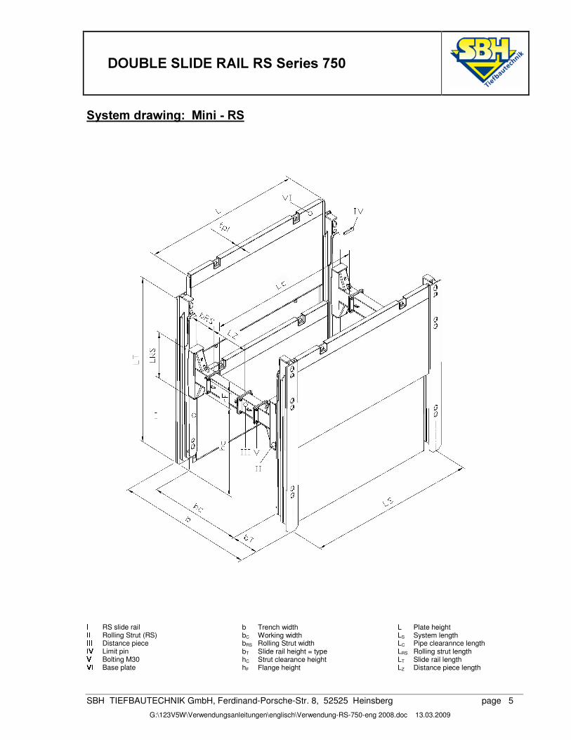
6\VWHP�GUDZLQJ���0LQL���56��
� RS slide rail � � Rolling Strut (RS) � � � Distance piece � � Limit pin �
Bolting M30 ��� Base plate
b Trench width bC Working width bRS Rolling Strut width bT Slide rail height = type hC Strut clearance height hF Flange height
L Plate height LS System length LC Pipe clearannce length LRS Rolling strut length LT Slide rail length LZ Distance piece length
����'28%/(�6/,'(�5$,/�56�6HULHV�����
SBH TIEFBAUTECHNIK GmbH, Ferdinand-Porsche-Str. 8, 52525 Heinsberg page 6
G:\123V5W\Verwendungsanleitungen\englisch\Verwendung-RS-750-eng 2008.doc 13.03.2009
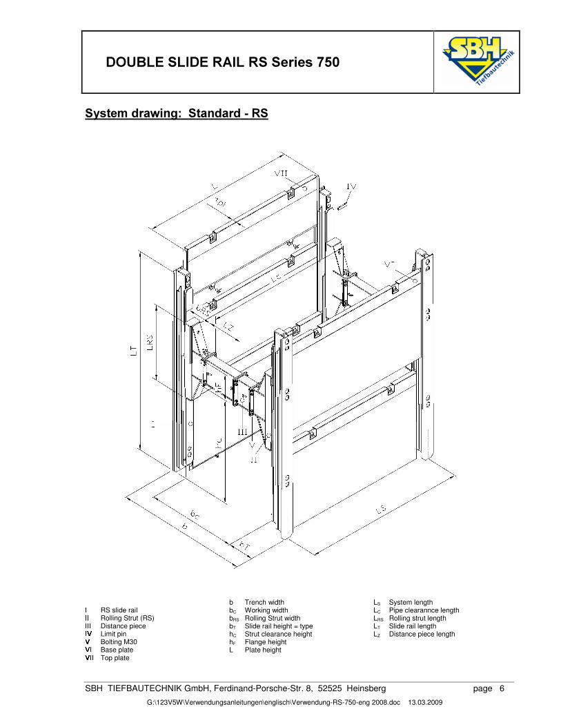
6\VWHP�GUDZLQJ���6WDQGDUG���56�� � RS slide rail � � Rolling Strut (RS) � � � Distance piece � � Limit pin �
Bolting M30 ��� Base plate
b Trench width bC Working width bRS Rolling Strut width bT Slide rail height = type hC Strut clearance height hF Flange height L Plate height
LS System length LC Pipe clearannce length LRS Rolling strut length LT Slide rail length LZ Distance piece length
��� � Top plate
����'28%/(�6/,'(�5$,/�56�6HULHV�����
SBH TIEFBAUTECHNIK GmbH, Ferdinand-Porsche-Str. 8, 52525 Heinsberg page 7
G:\123V5W\Verwendungsanleitungen\englisch\Verwendung-RS-750-eng 2008.doc 13.03.2009
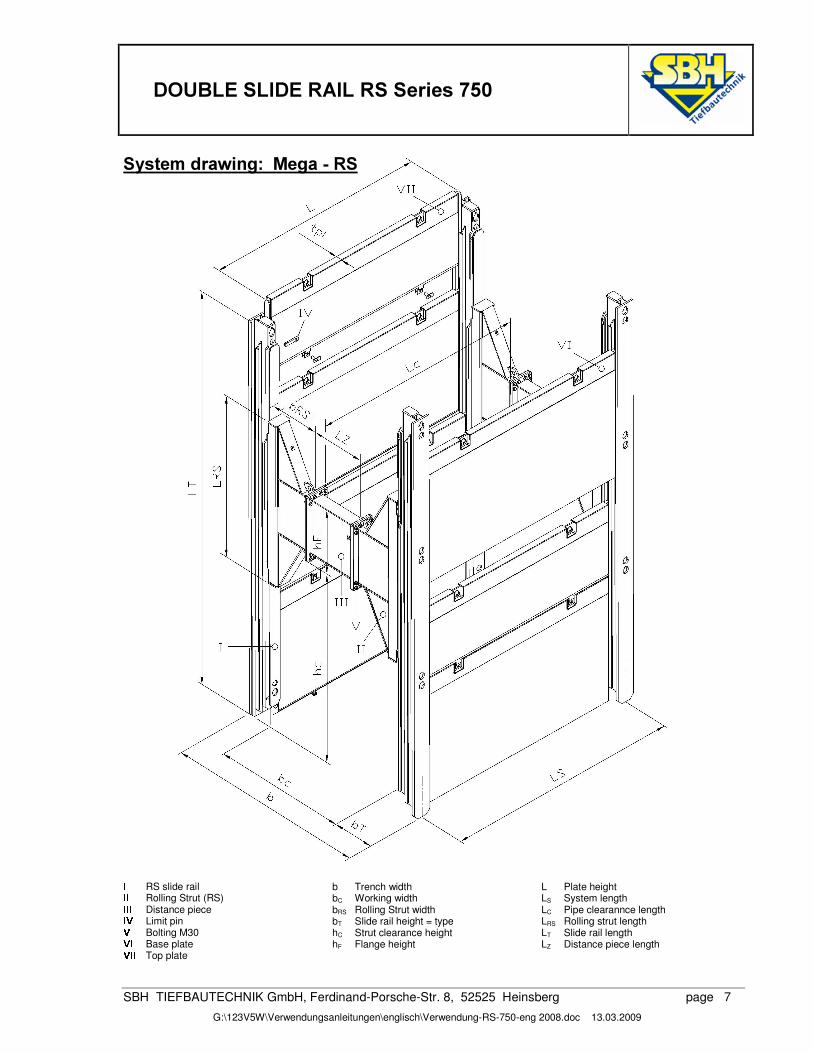
6\VWHP�GUDZLQJ���0HJD���56� � RS slide rail � � Rolling Strut (RS) � � � Distance piece � � Limit pin �
Bolting M30 ��� Base plate
b Trench width bC Working width bRS Rolling Strut width bT Slide rail height = type hC Strut clearance height hF Flange height
L Plate height LS System length LC Pipe clearannce length LRS Rolling strut length LT Slide rail length LZ Distance piece length��� �
Top plate
����'28%/(�6/,'(�5$,/�56�6HULHV�����
SBH TIEFBAUTECHNIK GmbH, Ferdinand-Porsche-Str. 8, 52525 Heinsberg page 9
G:\123V5W\Verwendungsanleitungen\englisch\Verwendung-RS-750-eng 2008.doc 13.03.2009
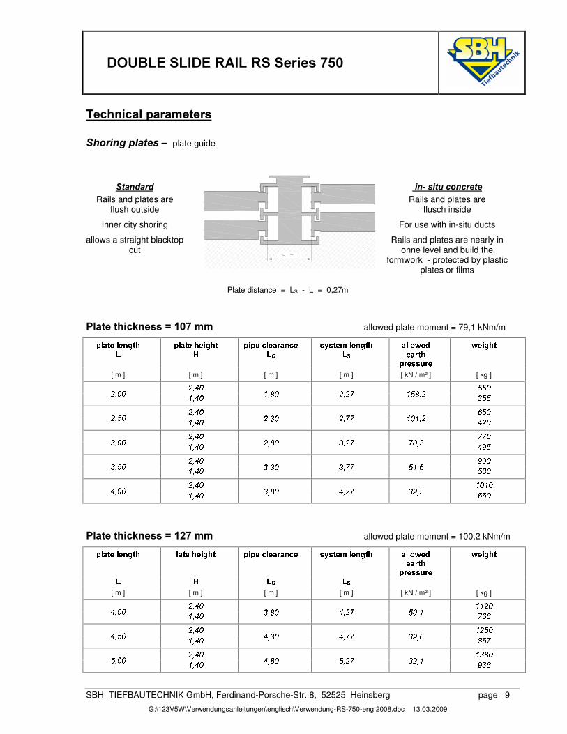
7HFKQLFDO�SDUDPHWHUV�6KRULQJ�SODWHV�±� plate guide
6WDQGDUG��
�LQ��VLWX�FRQFUHWH�Rails and plates are
flush outside Rails and plates are
flusch inside
Inner city shoring � For use with in-situ ducts
allows a straight blacktop cut
� Rails and plates are nearly in onne level and build the
formwork - protected by plastic plates or films
Plate distance = LS - L = 0,27m
3ODWH�WKLFNQHVV� �����PP� �allowed plate moment = 79,1 kNm/m���� ����� ��� ��� ��� ��������� ����� ��� ���� � ����������� ������������ �� � ��� ��� � �� !�" # � �����$ % $�& $�' �� �����
�(�)��� *(��[ m ] [ m ] [ m ] [ m ] [ kN / m² ] [ kg ] +), -�. /�/�.+), .�. 0 , -�. 0 , 1�. +), +(2 0 /�13, + 4 /�/
+), -�. 5)/�.+), /�. 0 , -�. +), 4 . +),�2�2 0 . 0 , + -�+�.+), -�. 2�2).4 , .�. 0 , -�. +), 1�. 4 , +(2 26.3, 4 -�7�/+), -�. 7�.�.4 , /�. 0 , -�. 4 , 4 . 4 ,�2�2 / 0 ,�5 /�1�.+), -�. 0 . 0 .-), .�. 0 , -�. 4 , 1�. -�, +(2 4 73,/ 5)/�.
3ODWH�WKLFNQHVV� �����PP� �allowed plate moment = 100,2 kNm/m
��� ���8� ��� ��� � ��� �� �� ����� ��� ���� � ����������� ������������ �� � ��� ��� � �� !�"�� �����
�(�)��� *(�� # � �����
$ % $�& $�'[ m ] [ m ] [ m ] [ m ] [ kN / m² ] [ kg ] +), -�. 0�0 +�.-), .�. 0 , -�. 4 , 1�. -�, +(2 /�.3, 0 265�5
+), -�. 0 +�/�.-), /�. 0 , -�. -�, 4 . -�,�2�2 4 73,�5 1�/�2+), -�. 0 4 1�./3, .�. 0 , -�. -�, 1�. /6, +(2 4 +6, 0 7 4 5
����'28%/(�6/,'(�5$,/�56�6HULHV�����
SBH TIEFBAUTECHNIK GmbH, Ferdinand-Porsche-Str. 8, 52525 Heinsberg page 10
G:\123V5W\Verwendungsanleitungen\englisch\Verwendung-RS-750-eng 2008.doc 13.03.2009
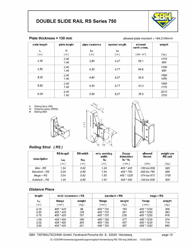
3ODWH�WKLFNQHVV� �����PP� � allowed plate moment = 164,3 kNm/m
��� ����� ��� ��� ��� ��������� ����� ��� ���� � ����������� ������������ �� � ��� ��� � �� !�"���������(�������9
# � �����$ % $ & $ '
[ m ] [ m ] [ m ] [ m ] [ kN / m² ] [ kg ] +), -�. 0 4 26.-), .�. 0 , -�. 4 , 1�. -�, +(2 1�+6, 0 1�1�.+), -�. 0 / 4 .-), /�. 0 , -�. -�, 4 . -�,�2�2 56-),7 7�1�.+), -�. 0 5�7�./3, .�. 0 , -�. -�, 1�. /6, +(2 /�+6,�5 0 .�26.+), -�. 0 1�/�./6, /�. 0 , -�. /6, 4 . /6,�2�2 - 4 , - 0�0 26.+), -�. +�+ 0 .5:, .�. 0 , -�. /6, 1�. 53, +(2 4 5:,/ 0 4 26.
; ; Rolling Strut (RS) ; ; ; Distance piece (ZWSt) < Bolting M30
5ROOLQJ�6WUXW�����56���=?>A@ � ������� =?>A@ �� "���� �B� ��9: !���DC�� ���
�� " ���E � � ���
"�� �������� ������ � �� !�"E �����)��
# � ������� ��=F>A@ ����� �$�G ' H G ' H�& H�I�J � I" ������D� ����� ���[ m ] [ m ] [ m ] [ mm ] [ kN ] [ kg ] KML N�L6O�PRQ 0 , +�- .6,5)+ 0 , +�- -�.�/�S�-�+�. O 0 .�.MT�L U!5 4 7 5)+�.
QWV X�N�Y�X�ZYM[�P\Q +), .�- .6,5)+ 0 , +�- -�.�/�S?23+�. O�+�.�.MT�L U�2)1�. 7�1�.K!]�^�X_[�P\Q 4 , .�- .6, 7�+ 0 , 1 4 -�.�/�S 0 +�+�. O 4 23-!T�L U#7�2 4 0 2).�.`\a�b U�V c�d3eR[�P\Q 0 , +�- .6,5)+ 0 , +�- -�.�/�S�-�+�. O 0 .�.MT�L U!5 4 7 5)+�.
'LVWDQFH�3LHFH� � � �� ������� �B� ���:f�)g�� ���(� �W�!h =?> ���� ��"�����"�h =?> ����(�Mh =A>$�i E � � ��� !�� ����� E � ��� � # � ����� E � � ��� !�� �����
[ m ] [ mm ] [ kg ] [ mm ] [ kg ] [ mm ] [ kg ] .6, +�/ -�.�/�S�-�+�. 7�7 -�.�/�S?2:+�. 0 5 4 -�.�/�S 0 +�+�. 4 .�5.6, /�. -�.�/�S�-�+�. 0 +�1 -�.�/�S?2:+�. +�. 0 -�.�/�S 0 +�+�. 4 5 4.6,�2)/ -�.�/�S�-�+�. 0 /�2 -�.�/�S?2:+�. + 4 7 -�.�/�S 0 +�+�. - 0 10 , .�. -�.�/�S�-�+�. 0 1�/ -�.�/�S?2:+�. +�2�2 -�.�/�S 0 +�+�. -�23-+), .�. -�.�/�S�-�+�. 4 . 4 -�.�/�S?2:+�. - 4 2 -�.�/�S 0 +�+�. 2 0 -4 , .�. -�.�/�S�-�+�. -�+ 0 -�.�/�S?2:+�. /�7 2 -�.�/�S 0 +�+�. 7�5�.
����'28%/(�6/,'(�5$,/�56�6HULHV�����
SBH TIEFBAUTECHNIK GmbH, Ferdinand-Porsche-Str. 8, 52525 Heinsberg page 11
G:\123V5W\Verwendungsanleitungen\englisch\Verwendung-RS-750-eng 2008.doc 13.03.2009
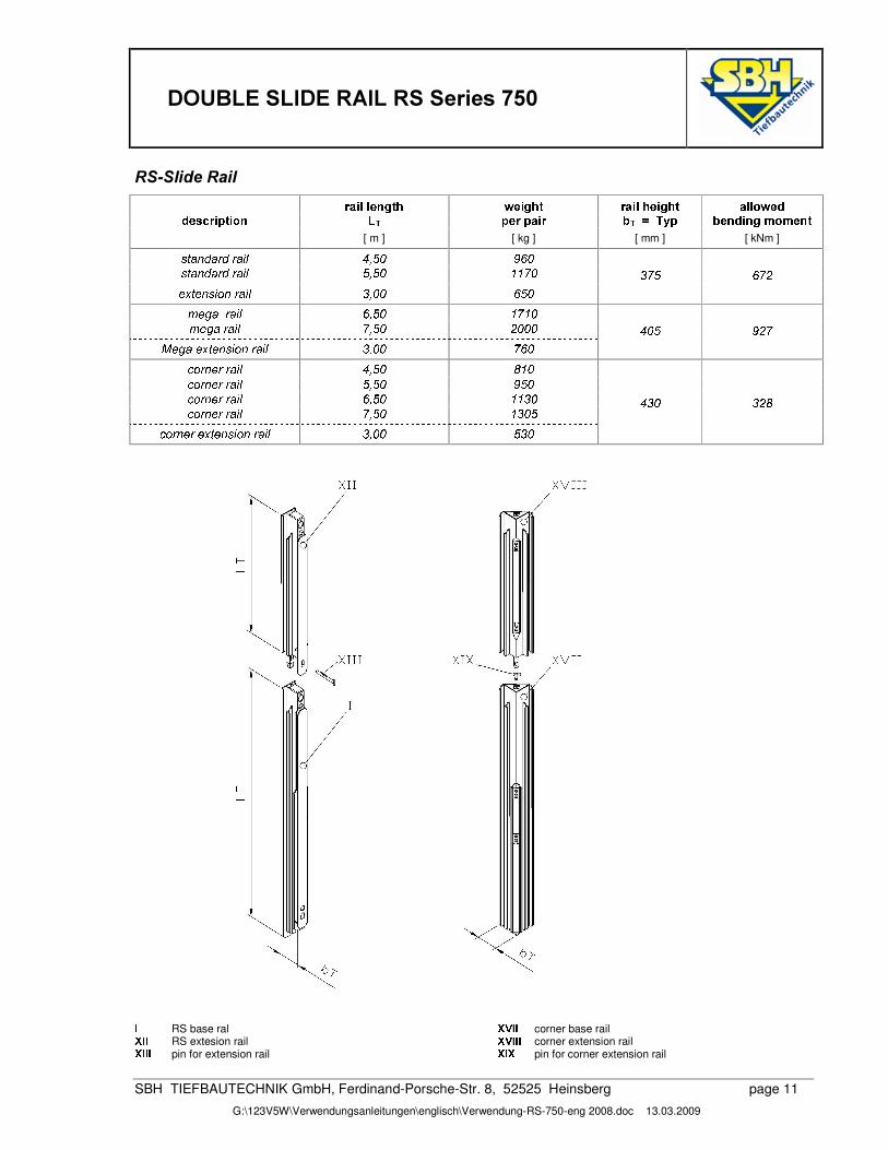
56�6OLGH�5DLO����� ��� �� � ��� # � ����� ���� �)���� ����� � � � �� #�"
" ������D� ����� ��� $�j �� �F��� � � H jlknm ��� H ���"W� � �B���������� [ m ] [ kg ] [ mm ] [ kNm ] U)V X�N�Y�X�ZY!ZX)L o -), /�. 7�5�.
U)V X�N�Y�X�ZY!ZX)L o /3, /�. 0�0 26.]:p�V ]�N�U3L c�N�ZX�L o 4 , .�. 5�/�.
4 26/ 5�23+
q ]�^�XrZX�L o 5:, /�. 0 2 0 .q ]�^�X!ZX�L o 2s, /�. +�.�.�.
Kt]�^�X!]:p V ]�N�U3L c�N!Z�X)L o 4 , .�. 2)5�.-�.�/ 7�+�2
d:c�Z N�]�Z�ZX�L o -), /�. 1 0 .d:c�Z N�]�Z�ZX�L o /3, /�. 7�/�.d:c�Z N�]�Z�ZX�L o 5:, /�. 0�0 4 .d:c�Z N�]�Z�ZX�L o 2s, /�. 0 4 .�/
d3c�ZN�]�Z�]:p�V ]�N�U3L c�N!Z�X�L o 4 , .�. / 4 .- 4 . 4 +�1
; RS base ral u�; ;
RS extesion rail u�; ; ; pin for extension rail
u�<(; ; corner base rail u�<(; ; ; corner extension rail uW; u
pin for corner extension rail
����'28%/(�6/,'(�5$,/�56�6HULHV�����
SBH TIEFBAUTECHNIK GmbH, Ferdinand-Porsche-Str. 8, 52525 Heinsberg page 11
G:\123V5W\Verwendungsanleitungen\englisch\Verwendung-RS-750-eng 2008.doc 13.03.2009
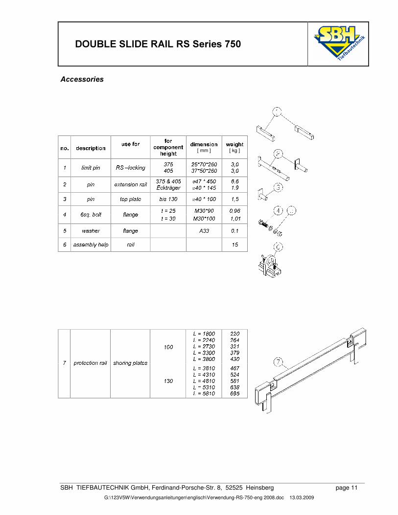
$FFHVVRULHV���
� � ����W9 "�)� ���D� ���D� ��� *��� E ��� E �W�
���(�8�������������� �W���
"�� ������ � ���[ mm ]
# � �����[ kg ]
0 o L q L V:v L N P\Q�[�o c�d:e3L N�^ 4 2)/-�.�/
+�/ S�2). S+�5�.4 2�S/�. S+�5�.4 , .4 , .
+ v�L N ]:p�V ]�N�U3L c�N�ZX�L o 4 26/twx-�.�/yFdze�V Z{�^�]�Z |
-(2tS�-�/�.|-�.�S 0 - /
5:,50 , 74 v�L N V c:vtv o X�V ] T�L U 0 4 .
|-�.�S 0 .�. 0 , /
V�}!+�/ K 4 . S�7�. .3, 7�5- 5:U)~��)T�c)o V b o X�N�^�] V�} 4 . K 4 . S 0 .�. 0 ,. 0/ �AX�U3��]�Z b o X�N�^�] ` 4�4 .3, 0
5�X)U6U6] q T�o �M��])o v ZX�L o 0 /
�
0 .�.��} 0 1�.�.��}!+�+)- .��}!+(2 4 .��} 4�4 .�.��} 4 1�.�.
+�+�.+�56-4 + 04 267- 4 .2�v(Z c�V ]�d)V L c�NtZ�X)L o�U3��c�Z L N�^_v o X�V ]�U
0 4 .��} 4 1 0 .��}#- 4 0 .��}#- 1 0 .��}t/ 4 0 .��}t/�1 0 .
- 5�2/�+�-/�1 05 4 15�7�/
�
����'28%/(�6/,'(�5$,/�56�6HULHV�����
SBH TIEFBAUTECHNIK GmbH, Ferdinand-Porsche-Str. 8, 52525 Heinsberg page 12
G:\123V5W\Verwendungsanleitungen\englisch\Verwendung-RS-750-eng 2008.doc 13.03.2009
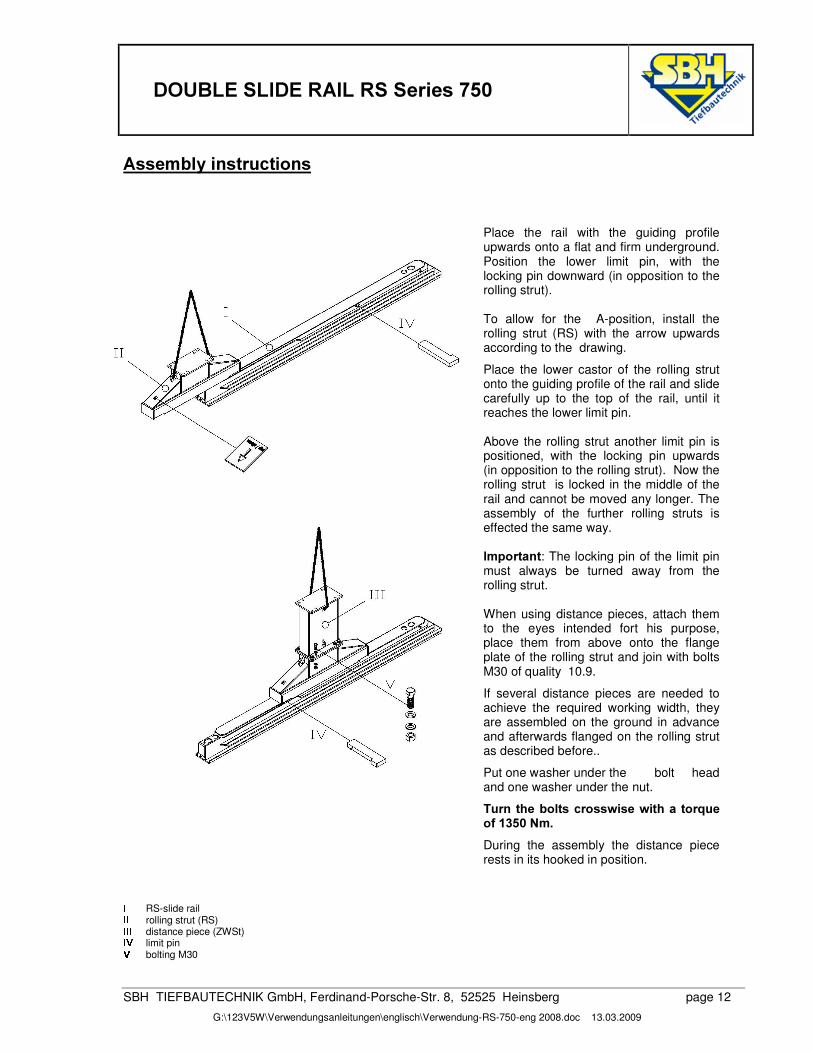
$VVHPEO\�LQVWUXFWLRQV�
Place the rail with the guiding profile upwards onto a flat and firm underground. Position the lower limit pin, with the locking pin downward (in opposition to the rolling strut). To allow for the A-position, install the rolling strut (RS) with the arrow upwards according to the drawing.
Place the lower castor of the rolling strut onto the guiding profile of the rail and slide carefully up to the top of the rail, until it reaches the lower limit pin. Above the rolling strut another limit pin is positioned, with the locking pin upwards (in opposition to the rolling strut). Now the rolling strut is locked in the middle of the rail and cannot be moved any longer. The assembly of the further rolling struts is effected the same way. ,PSRUWDQW: The locking pin of the limit pin must always be turned away from the rolling strut. When using distance pieces, attach them to the eyes intended fort his purpose, place them from above onto the flange plate of the rolling strut and join with bolts M30 of quality 10.9.
If several distance pieces are needed to achieve the required working width, they are assembled on the ground in advance and afterwards flanged on the rolling strut as described before..
Put one washer under the bolt head and one washer under the nut.
7XUQ�WKH�EROWV�FURVVZLVH�ZLWK�D�WRUTXH�RI������1P� During the assembly the distance piece rests in its hooked in position.
; RS-slide rail ; ; rolling strut (RS) ; ; ; distance piece (ZWSt) ; < limit pin <
bolting M30
����'28%/(�6/,'(�5$,/�56�6HULHV�����
SBH TIEFBAUTECHNIK GmbH, Ferdinand-Porsche-Str. 8, 52525 Heinsberg page 13
G:\123V5W\Verwendungsanleitungen\englisch\Verwendung-RS-750-eng 2008.doc 13.03.2009
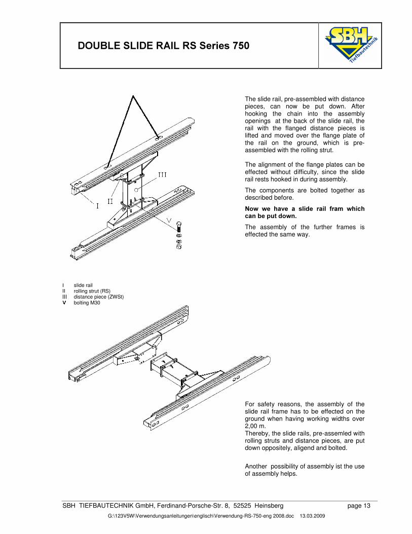
The slide rail, pre-assembled with distance pieces, can now be put down. After hooking the chain into the assembly openings at the back of the slide rail, the rail with the flanged distance pieces is lifted and moved over the flange plate of the rail on the ground, which is pre-assembled with the rolling strut. The alignment of the flange plates can be effected without difficulty, since the slide rail rests hooked in during assembly.
The components are bolted together as described before.
1RZ� ZH� KDYH� D� VOLGH� UDLO� IUDP� ZKLFK�FDQ�EH�SXW�GRZQ��The assembly of the further frames is effected the same way.
; slide rail ; ; rolling strut (RS) ; ; ; distance piece (ZWSt) < bolting M30
For safety reasons, the assembly of the slide rail frame has to be effected on the ground when having working widths over 2,00 m. Thereby, the slide rails, pre-assemled with rolling struts and distance pieces, are put down oppositely, aligend and bolted.
Another possibility of assembly ist the use of assembly helps.
����'28%/(�6/,'(�5$,/�56�6HULHV�����
SBH TIEFBAUTECHNIK GmbH, Ferdinand-Porsche-Str. 8, 52525 Heinsberg page 14
G:\123V5W\Verwendungsanleitungen\englisch\Verwendung-RS-750-eng 2008.doc 13.03.2009
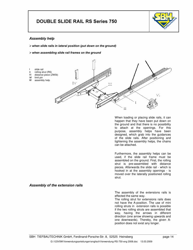
$VVHPEO\�KHOS��¾ ZKHQ�VOLGH�UDLOV�LQ�ODWHUDO�SRVLWLRQ��SXW�GRZQ�RQ�WKH�JURXQG��
�¾ ZKHQ�DVVHPEOLQJ�VOLGH�UDLO�IUDPHV�RQ�WKH�JURXQG�����;
slide rail ; ; rolling strut (RS) ; ; ; distance piece (ZWSt) ; < limit pin <�; assembly help
�����
When loading or placing slide rails, it can happen that they have been put down on the ground and that there is no possibility to attach at the openings. For this purpose, assembly helps have been designed, which grab into the guidances of the slide rails. After positioning and tightening the assembly helps, the chains can be attached.
Furthermore, the assembly helps can be used, if the slide rail frame must be assembled on the ground. First, the rolling strut is pre-assembled with distance pieces. Afterwards the slide rail - which is hooked in at the assembly openings - is moved over the laterally positioned rolling strut.
$VVHPEO\�RI�WKH�H[WHQVLRQ�UDLOV�
The assembly of the extensions rails is effected the same way. The rolling strut for extensions rails does not have the A-position. The use of mini rolling struts in extension rails is possible if the two rolling struts are assembled that way, having the arrows in different direction (one arrow showing upwards and one downwards). Thereby, the given A-position does not exist any longer.
����'28%/(�6/,'(�5$,/�56�6HULHV�����
SBH TIEFBAUTECHNIK GmbH, Ferdinand-Porsche-Str. 8, 52525 Heinsberg page 15
G:\123V5W\Verwendungsanleitungen\englisch\Verwendung-RS-750-eng 2008.doc 13.03.2009
,QVWDOODWLRQ�LQVWUXFWLRQV�$OORZHG�WHQVLOH�IRUFHV�
At the single attachement points the folliwng tensile forces can be beared:
VOLGH�UDLO� per lifting eye = 196 kN per guiding profile opening = 164 kN
SODWHV� per lifting eye = 196 kN per eye at cutting edge = 49 kN
UROOLQJ�VWUXW� per lifting eye = 164 kN
GLVWDQFH�SLHFH� je hooking eye = 49 kN
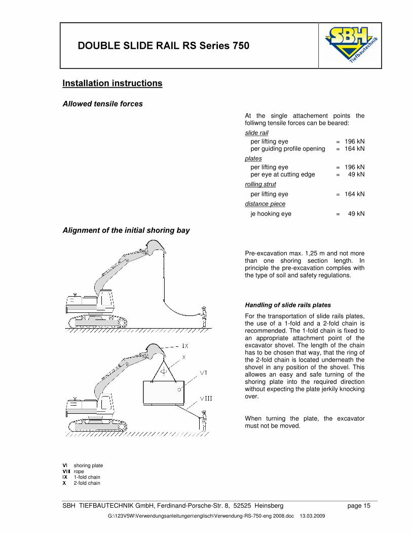
�$OLJQPHQW�RI�WKH�LQLWLDO�VKRULQJ�ED\�
Pre-excavation max. 1,25 m and not more than one shoring section length. In principle the pre-excavation complies with the type of soil and safety regulations.
�+DQGOLQJ�RI�VOLGH�UDLOV�SODWHV�For the transportation of slide rails plates, the use of a 1-fold and a 2-fold chain is recommended. The 1-fold chain is fixed to an appropriate attachment point of the excavator shovel. The length of the chain has to be chosen that way, that the ring of the 2-fold chain is located underneath the shovel in any position of the shovel. This allowes an easy and safe turning of the shoring plate into the required direction without expecting the plate jerkily knocking over.
When turning the plate, the excavator must not be moved.
���<�;
shoring plate <�; ; ; rope ; u
1-fold chain u 2-fold chain
����'28%/(�6/,'(�5$,/�56�6HULHV�����
SBH TIEFBAUTECHNIK GmbH, Ferdinand-Porsche-Str. 8, 52525 Heinsberg page 16
G:\123V5W\Verwendungsanleitungen\englisch\Verwendung-RS-750-eng 2008.doc 13.03.2009
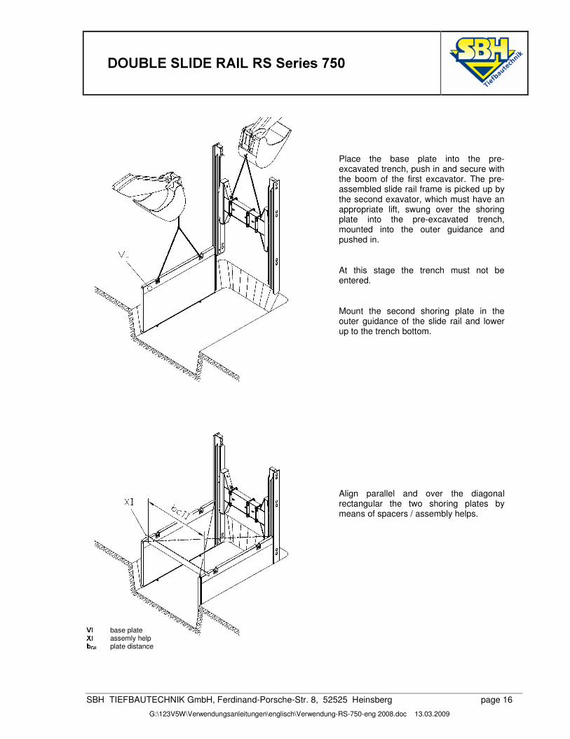
Place the base plate into the pre-excavated trench, push in and secure with the boom of the first excavator. The pre-assembled slide rail frame is picked up by the second exavator, which must have an appropriate lift, swung over the shoring plate into the pre-excavated trench, mounted into the outer guidance and pushed in.
At this stage the trench must not be entered.
Mount the second shoring plate in the outer guidance of the slide rail and lower up to the trench bottom.
Align parallel and over the diagonal rectangular the two shoring plates by means of spacers / assembly helps.
<�; base plate u�; assemly help �6��� �
plate distance
����'28%/(�6/,'(�5$,/�56�6HULHV�����
SBH TIEFBAUTECHNIK GmbH, Ferdinand-Porsche-Str. 8, 52525 Heinsberg page 17
G:\123V5W\Verwendungsanleitungen\englisch\Verwendung-RS-750-eng 2008.doc 13.03.2009
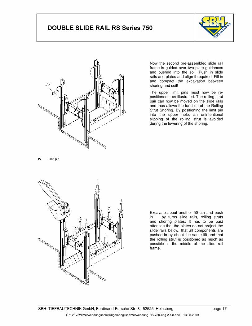
Now the second pre-assembled slide rail frame is guided over two plate guidances and pushed into the soil. Push in slide rails and plates and align if required. Fill in and compact the excavation between shoring and soil!
The upper limit pins must now be re-positioned – as illustrated. The rolling strut pair can now be moved on the slide rails and thus allows the function of the Rolling Strut Shoring. By positioning the limit pin into the upper hole, an unintentional slipping of the rolling strut is avoided during the lowering of the shoring.
; <
limit pin
�
Excavate about another 50 cm and push in by turns slide rails, rolling struts and shoring plates. It has to be paid attention that the plates do not project the slide rails below, that all components are pushed in by about the same lift and that the rolling strut is positioned as much as possible in the middle of the slide rail frame.
����'28%/(�6/,'(�5$,/�56�6HULHV�����
SBH TIEFBAUTECHNIK GmbH, Ferdinand-Porsche-Str. 8, 52525 Heinsberg page 18
G:\123V5W\Verwendungsanleitungen\englisch\Verwendung-RS-750-eng 2008.doc 13.03.2009
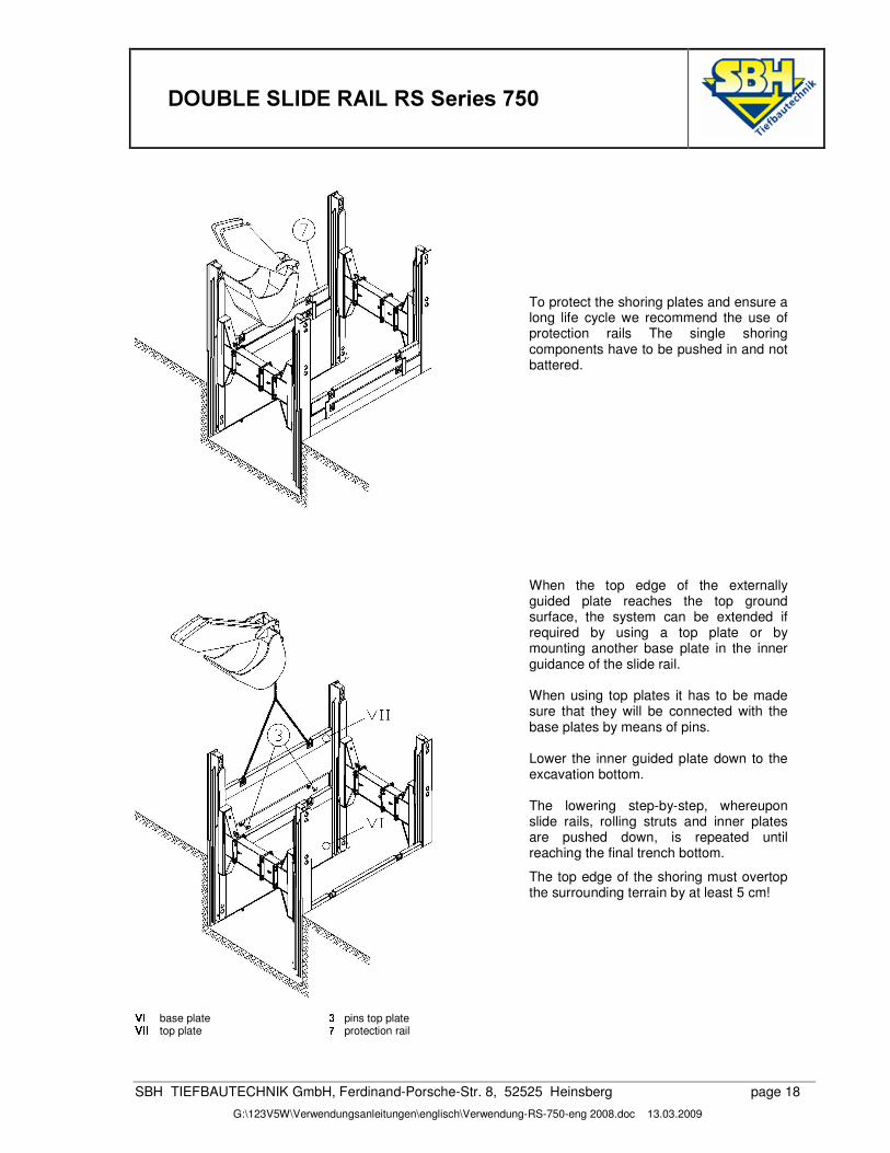
To protect the shoring plates and ensure a long life cycle we recommend the use of protection rails The single shoring components have to be pushed in and not battered. When the top edge of the externally guided plate reaches the top ground surface, the system can be extended if required by using a top plate or by mounting another base plate in the inner guidance of the slide rail. When using top plates it has to be made sure that they will be connected with the base plates by means of pins. Lower the inner guided plate down to the excavation bottom. The lowering step-by-step, whereupon slide rails, rolling struts and inner plates are pushed down, is repeated until reaching the final trench bottom.
The top edge of the shoring must overtop the surrounding terrain by at least 5 cm!
<�;
base plate � pins top plate <�; ; top plate � protection rail
�
����'28%/(�6/,'(�5$,/�56�6HULHV�����
SBH TIEFBAUTECHNIK GmbH, Ferdinand-Porsche-Str. 8, 52525 Heinsberg page 19
G:\123V5W\Verwendungsanleitungen\englisch\Verwendung-RS-750-eng 2008.doc 13.03.2009
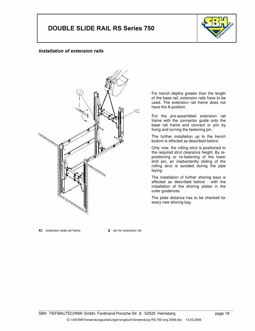
,QVWDOODWLRQ�RI�H[WHQVLRQ�UDLOV �
For trench depths greater than the length of the base rail, extension rails have to be used. The extension rail frame does not have the A-position. Put the pre-assembled extension rail frame with the connector guide onto the base rail frame and connect or join by fixing and turning the fastening pin.
The further installation up to the trench bottom is effected as described before.
Only now, the rolling strut is positioned to the required strut clearance height. By re-positioning or re-fastening of the lower limit pin, an inadvertently sliding of the rolling strut is avoided during the pipe laying.
The installation of further shoring bays is effected as described before - with the installation of the shoring plates in the outer guidances.
The plate distance has to be checked for every new shoring bay.
u�; ;
extension slide rail frame � pin for extension rail
����'28%/(�6/,'(�5$,/�56�6HULHV�����
SBH TIEFBAUTECHNIK GmbH, Ferdinand-Porsche-Str. 8, 52525 Heinsberg page 20
G:\123V5W\Verwendungsanleitungen\englisch\Verwendung-RS-750-eng 2008.doc 13.03.2009
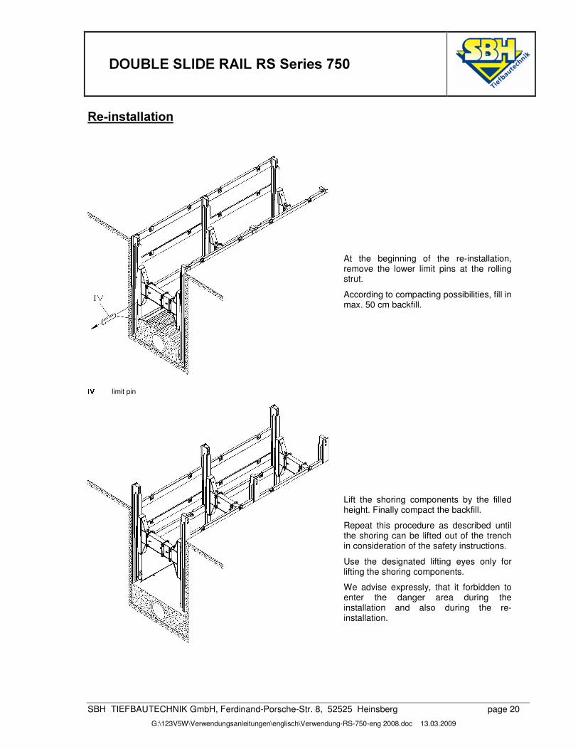
5H�LQVWDOODWLRQ�
At the beginning of the re-installation, remove the lower limit pins at the rolling strut.
According to compacting possibilities, fill in max. 50 cm backfill.
; < limit pin
Lift the shoring components by the filled height. Finally compact the backfill.
Repeat this procedure as described until the shoring can be lifted out of the trench in consideration of the safety instructions.
Use the designated lifting eyes only for lifting the shoring components.
We advise expressly, that it forbidden to enter the danger area during the installation and also during the re-installation.
�
����'28%/(�6/,'(�5$,/�56�6HULHV�����
SBH TIEFBAUTECHNIK GmbH, Ferdinand-Porsche-Str. 8, 52525 Heinsberg page 21
G:\123V5W\Verwendungsanleitungen\englisch\Verwendung-RS-750-eng 2008.doc 13.03.2009
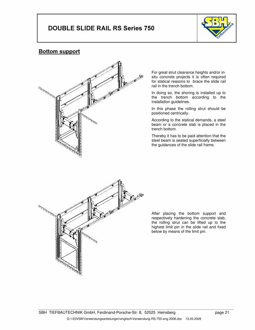
%RWWRP�VXSSRUW�
�For great strut clearance heights and/or in-situ concrete projects it is often required for statical reasons to brace the slide rail rail in the trench bottom.
In doing so, the shoring is installed up to the trench bottom according to the installation guidelines.
In this phase the rolling strut should be positioned centrically.
According to the statical demands, a steel beam or a concrete slab is placed in the trench bottom.
Thereby it has to be paid attention that the steel beam is seated superficially between the guidances of the slide rail frame.
After placing the bottom support and respectively hardening the concrete slab, the rolling strut can be lifted up to the highest limit pin in the slide rail and fixed below by means of the limit pin.
�
����'28%/(�6/,'(�5$,/�56�6HULHV�����
SBH TIEFBAUTECHNIK GmbH, Ferdinand-Porsche-Str. 8, 52525 Heinsberg page 22
G:\123V5W\Verwendungsanleitungen\englisch\Verwendung-RS-750-eng 2008.doc 13.03.2009
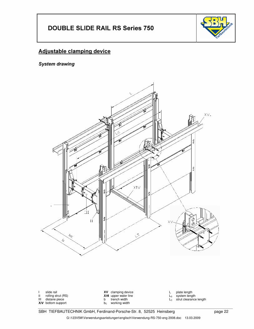
$GMXVWDEOH�FODPSLQJ�GHYLFH�6\VWHP�GUDZLQJ���������������������������������������� ; slide rail ; ; rolling strut (RS) ; ; ; distane piece u�; <
bottom support
u�< clamping device u�<(; upper waler line
b trench width bC working width
L plate length LS system length LC strut clearance length
����'28%/(�6/,'(�5$,/�56�6HULHV�����
SBH TIEFBAUTECHNIK GmbH, Ferdinand-Porsche-Str. 8, 52525 Heinsberg page 23
G:\123V5W\Verwendungsanleitungen\englisch\Verwendung-RS-750-eng 2008.doc 13.03.2009
7HFKQLFDO�SDUDPHWHUV������� ���)� ���D� ���D� ���
��� ��� � � � ��� �[ mm ]
� � � �����[ kg ]
� �3�� :¡6¢�£ �¥¤�¦�§¥�:¨�¦�§©�¤�¦ ª(��« ¬¤ ®)¯ ª�¦ §¥�s¤�¦�§�©�¤�¦ ¤�°3« ±¬ ² ³�´�¯�¢¶µ� ³�£ ¢ ¬�¦ §�©�©�©�§�©�¤�¦ ª�¨3«¦± £ ·�¸¢�³�¹�¢�¹!¸��¹
g¤�ª3« ©�§º�z¦�¦�¦ � ±�« ©�¦
© »A³��3·�¢�¸ ¼º½�¾ ¬F� ¦6« ¦�©ª ª6¿ �)À�®�³�¸�¢�¹!´�®�£ ¤�ª3«© ¦6« ©�±
Strut-free pits, e.g. for the laying of long pipes, for building a structure or for placing a press drilling machine can be realised with the adjustable clamping device.
After assembling the clamping device, one or several rolling struts can be dismounted. The slide rail frames which have to be strut-free afterwards, must be about 1,35 m longer than the required trench depth. This clearance is required for the bottom support at the slide rail end and for fixing the clamping device above the trench.
The clamping device engages behind the outer rail guidance and clamps the outside horizontal upper waler. The upper forces, passed in by the slide rail, are transfered over the outer waler to the corner slide rails.
,QVWDOODWLRQ�LQVWUXFWLRQV
After installing the rolling strut shoring and bracing the slide rail frames in the trench bottom (bottom support), the clamping device can be assembled above the trench.
Therefor the lower socket which is pre-assembled with threaded rods, is moved over the rail guidance and put down on the top ground surface. The lower lug keeps the two threaded rods at bay and serves also as lining of the upper waler. More linings, distributed over the length of the waler, can be made up of square-shaped timber for example.
The dimensioning of the waler acts in accordance with the statical requirements, whereas also 2 walers can be placed back-to-back.
Behind the slide rail, the waler is put down on the socket and lug. The upper socket, pre-assembled with threaded rods, is also moved the slide rail guidance, fit with the lugs and put down on the waler. Move the flange plate over the 4 threaded rods and torque with the washers and nuts.
Now the upper limit pins in the slide rail frames can be removed and the rolling struts can be dismounted.
�
����'28%/(�6/,'(�5$,/�56�6HULHV�����
SBH TIEFBAUTECHNIK GmbH, Ferdinand-Porsche-Str. 8, 52525 Heinsberg page 24
G:\123V5W\Verwendungsanleitungen\englisch\Verwendung-RS-750-eng 2008.doc 13.03.2009
3LWV�6\VWHP�GUDZLQJ�
Á Â�à Ã
corner base rail Á Â�à à à corner extension rail Á�à Á
pin Â�à Ä3Â�à à plate
b trench width bC working width L plate length LT slide rail length
����'28%/(�6/,'(�5$,/�56�6HULHV�����
SBH TIEFBAUTECHNIK GmbH, Ferdinand-Porsche-Str. 8, 52525 Heinsberg page 26
G:\123V5W\Verwendungsanleitungen\englisch\Verwendung-RS-750-eng 2008.doc 13.03.2009
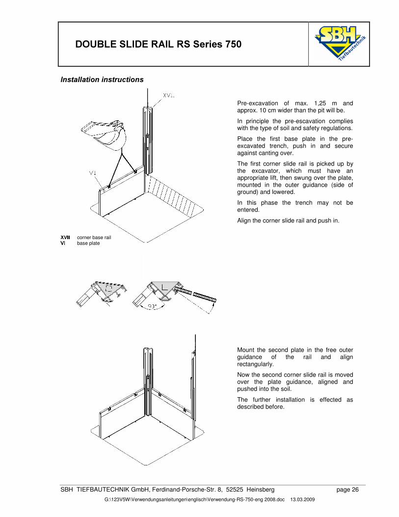
,QVWDOODWLRQ�LQVWUXFWLRQV��Pre-excavation of max. 1,25 m and approx. 10 cm wider than the pit will be.
In principle the pre-escavation complies with the type of soil and safety regulations.
Place the first base plate in the pre-excavated trench, push in and secure against canting over.
The first corner slide rail is picked up by the excavator, which must have an appropriate lift, then swung over the plate, mounted in the outer guidance (side of ground) and lowered.
In this phase the trench may not be entered.
Align the corner slide rail and push in.
Á Â�à à corner base rail Â�Ã
base plate
Mount the second plate in the free outer guidance of the rail and align rectangularly.
Now the second corner slide rail is moved over the plate guidance, aligned and pushed into the soil.
The further installation is effected as described before.
����'28%/(�6/,'(�5$,/�56�6HULHV�����
SBH TIEFBAUTECHNIK GmbH, Ferdinand-Porsche-Str. 8, 52525 Heinsberg page 27
G:\123V5W\Verwendungsanleitungen\englisch\Verwendung-RS-750-eng 2008.doc 13.03.2009
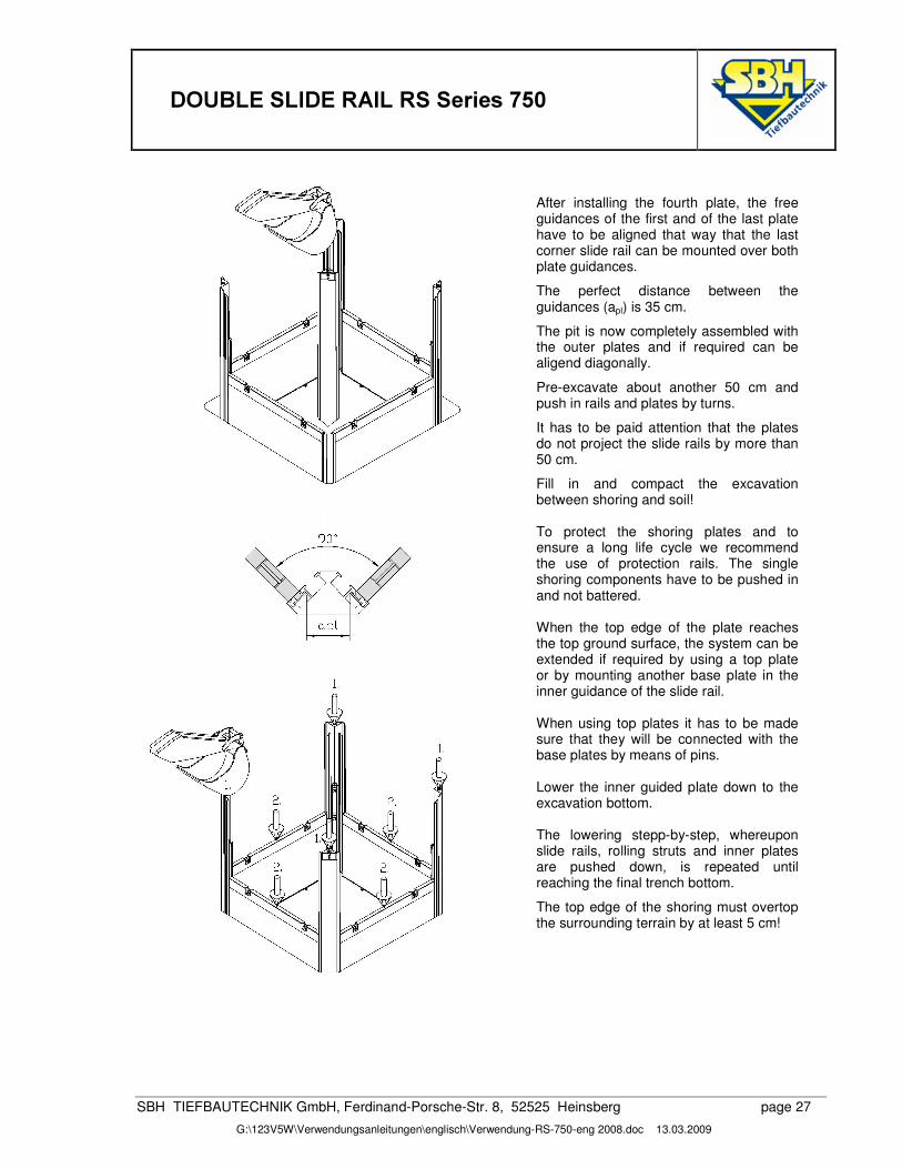
After installing the fourth plate, the free guidances of the first and of the last plate have to be aligned that way that the last corner slide rail can be mounted over both plate guidances.
The perfect distance between the guidances (apl) is 35 cm.
The pit is now completely assembled with the outer plates and if required can be aligend diagonally.
Pre-excavate about another 50 cm and push in rails and plates by turns.
It has to be paid attention that the plates do not project the slide rails by more than 50 cm.
Fill in and compact the excavation between shoring and soil! To protect the shoring plates and to ensure a long life cycle we recommend the use of protection rails. The single shoring components have to be pushed in and not battered. When the top edge of the plate reaches the top ground surface, the system can be extended if required by using a top plate or by mounting another base plate in the inner guidance of the slide rail. When using top plates it has to be made sure that they will be connected with the base plates by means of pins. Lower the inner guided plate down to the excavation bottom. The lowering stepp-by-step, whereupon slide rails, rolling struts and inner plates are pushed down, is repeated until reaching the final trench bottom.
The top edge of the shoring must overtop the surrounding terrain by at least 5 cm!
����'28%/(�6/,'(�5$,/�56�6HULHV�����
SBH TIEFBAUTECHNIK GmbH, Ferdinand-Porsche-Str. 8, 52525 Heinsberg page 28
G:\123V5W\Verwendungsanleitungen\englisch\Verwendung-RS-750-eng 2008.doc 13.03.2009
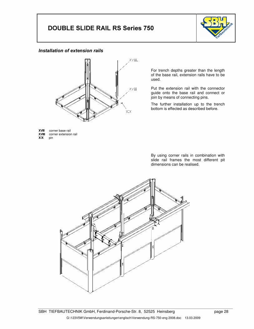
,QVWDOODWLRQ�RI�H[WHQVLRQ�UDLOV
�For trench depths greater than the length of the base rail, extension rails have to be used. Put the extension rail with the connector guide onto the base rail and connect or join by means of connecting pins.
The further installation up to the trench bottom is effected as described before.
Á Â�à Ã
corner base rail Á Â�à à à corner extension rail Á�à Á
pin
By using corner rails in combination with slide rail frames the most different pit dimensions can be realised.


![75,3 ,7,1(5$5< .LIDUX 6DIDUL 7DQ]DQLD · 2019. 5. 17. · &rqwdfw xv iru pruh lqirupdwlrq 75,3 ,7,1(5$5< .lidux zklfk lv nhsw frqvwdqwo\ doljkw 'hfrudwhg zlwk fdyh sdlqwlqjv wkh urrpv](https://img.pdfslide.us/doc/110x75/60ea0a9473fee72863275975/753-7155-lidux-6didul-7dqdqld-2019-5-17-rqwdfw-xv-iru-pruh.jpg)