Embed Size (px)
Citation preview
Surge ArrestersUltraSIL Polymer-Housed VariSTAR Surge Arresters: Normal-Duty (5 kA), Heavy-Duty (10 kA), and Heavy-Duty Riser Pole (10 kA)
Electrical Apparatus
235-35
10112 • Supersedes 0510
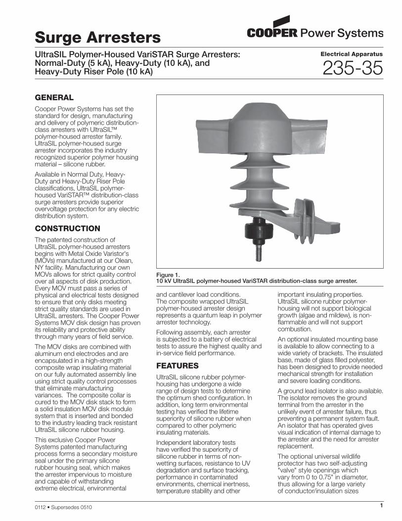
GEnErAlCooper Power Systems has set the standard for design, manufacturing and delivery of polymeric distribution-class arresters with UltraSIL™ polymer-housed arrester family. UltraSIL polymer-housed surge arrester incorporates the industry recognized superior polymer housing material – silicone rubber.
Available in Normal Duty, Heavy-Duty and Heavy-Duty Riser Pole classifications, UltraSIL polymer-housed VariSTAR™ distribution-class surge arresters provide superior overvoltage protection for any electric distribution system.
ConStruCtionThe patented construction of UltraSIL polymer-housed arresters begins with Metal Oxide Varistor's (MOVs) manufactured at our Olean, NY facility. Manufacturing our own MOVs allows for strict quality control over all aspects of disk production. Every MOV must pass a series of physical and electrical tests designed to ensure that only disks meeting strict quality standards are used in UltraSIL arresters. The Cooper Power Systems MOV disk design has proven its reliability and protective ability through many years of field service.
The MOV disks are combined with aluminum end electrodes and are encapsulated in a high-strength composite wrap insulating material on our fully automated assembly line using strict quality control processes that eliminate manufacturing variances. The composite collar is cured to the MOV disk stack to form a solid insulation MOV disk module system that is inserted and bonded to the industry leading track resistant UltraSIL silicone rubber housing.
This exclusive Cooper Power Systems patented manufacturing process forms a secondary moisture seal under the primary silicone rubber housing seal, which makes the arrester impervious to moisture and capable of withstanding extreme electrical, environmental
and cantilever load conditions. The composite wrapped UltraSIL polymer-housed arrester design represents a quantum leap in polymer arrester technology.
Following assembly, each arrester is subjected to a battery of electrical tests to assure the highest quality and in-service field performance.
fEAturESUltraSIL silicone rubber polymer-housing has undergone a wide range of design tests to determine the optimum shed configuration. In addition, long term environmental testing has verified the lifetime superiority of silicone rubber when compared to other polymeric insulating materials.
Independent laboratory tests have verified the superiority of silicone rubber in terms of non-wetting surfaces, resistance to UV degradation and surface tracking, performance in contaminated environments, chemical inertness, temperature stability and other
important insulating properties. UltraSIL silicone rubber polymer-housing will not support biological growth (algae and mildew), is non-flammable and will not support combustion.
An optional insulated mounting base is available to allow connecting to a wide variety of brackets. The insulated base, made of glass filled polyester, has been designed to provide needed mechanical strength for installation and severe loading conditions.
A ground lead isolator is also available. The isolator removes the ground terminal from the arrester in the unlikely event of arrester failure, thus preventing a permanent system fault. An isolator that has operated gives visual indication of internal damage to the arrester and the need for arrester replacement.
The optional universal wildlife protector has two self-adjusting "valve" style openings which vary from 0 to 0.75" in diameter, thus allowing for a large variety of conductor/insulation sizes
Figure 1. 10 kV UltraSIL polymer-housed VariSTAR distribution-class surge arrester.
2
UltraSIL Polymer-Housed VariSTAR Surge Arresters
while providing optimum wildlife protection. (See page 10, Figure 8 for a dimensional diagram.)
Customers looking to improve system reliability may specify the CooperGuard™ to minimize wildlife related outages. CooperGuard is easily retrofitted to existing arresters installations and provides increased electrical insulation for the high-voltage terminal of the arrester. The flexible design of CooperGuard allows insertion of the lead wire through the bottom of the integral molded flanges. The access holes molded above the flanges will allow conductor sizes ranging from 0 to 0.50” in diameter (OD). CooperGuard geometry allows water to shed away from the surface area of the animal guard while minimizing ice build up and maintaining flexibility through extreme operating temperatures. (Refer to page 10, Figure 9 for a dimensional diagram.)
opErAtionThe operation of VariSTAR arresters is typical of gapless metal oxide arresters. During steady state conditions, line-to-ground voltage is applied continuously across the arrester terminals. When surges occur, VariSTAR arresters immediately limits the overvoltage to the required protective level by conducting the surge current to ground. Upon passage of the surge, the arrester returns to its initial state, conducting minimal leakage current.
The protective characteristics of VariSTAR arresters provide excellent overvoltage protection for distribution system equipment. (See page 6 for protective characteristics.)
DESiGn tEStinGThe housing material, internals and hardware work together as a system and must stand up to years of exposure to environmental extremes. To assure a superior level of performance, both the components
and the assembled arrester units have been subjected to a program of testing that accurately simulates years of exposure to actual field conditions. Testing includes:
IEEE Std C62.11-2005™ standard �Testing – Full certification to performance requirements by an independent laboratory. A certified test report is available under Bulletin Number 95062.
Additional design verification testing of VariSTAR arrester include:
UV testing �Full dielectric testing �Wet Arc Tracking Resistance �Thermal Shock test �Multi-Stress Environmental test �cyclingTracking Wheel test �Coefficients of expansion for �materials compatibilityCantilever test �Terminal and Isolator Torque test �Hanger Mechanical Shock test �
This is only a partial listing of design tests performed on the VariSTAR distribution-class arrester. For detailed test reports and results please contact your Cooper Power Systems sales representative.
proDuCtion tEStSA complete production test program ensures a quality product. Each metal oxide varistor receives a series of electrical tests. Quality is demonstrated by a series of destructive tests performed on every batch of varistors. Listed are the tests performed on the varistors:
100% Physical Inspection �100% Discharge Voltage test �100% V � 1mA/cm2
100% Leakage Current at 80% �of V1mA/cm2 Voltage (Watts Loss)Batch High-current, Short- �duration testBatch Thermal Stability test �Batch Aging test �
Each fully assembled VariSTAR arrester must pass the following production tests:
100% Physical Inspection �100% Leakage Current test �100% Partial Discharge Inception �Voltage test
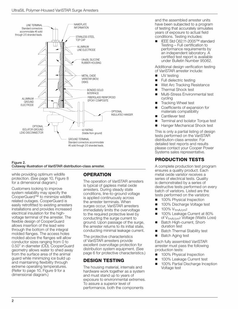
Figure 2. Cutaway illustration of VariSTAR distribution-class arrester.
ALUMINUMLINE ELECTRODE
METAL OXIDEVARISTAR (MOV)DISKS
ALUMINUMGROUND
ELECTRODE
NAMEPLATEINFORMATION
STAINLESS STEELTOP CAP
LINE TERMINALStandard connectors
accommodate #6 solidthrough 2/0 stranded leads.
UltraSIL SILICONERUBBER HOUSING
BONDED SOLIDINTERFACEFIBERGLASS REINFORCEDEPOXY COMPOSITE
OPTIONALINSULATED HANGER
OPTIONALISOLATOR GROUND
LEAD DISCONNECTORkV RATING(Visible from ground)
GROUND TERMINALStandard connectors accommodate#6 solid through 2/0 stranded leads.
235-35
3
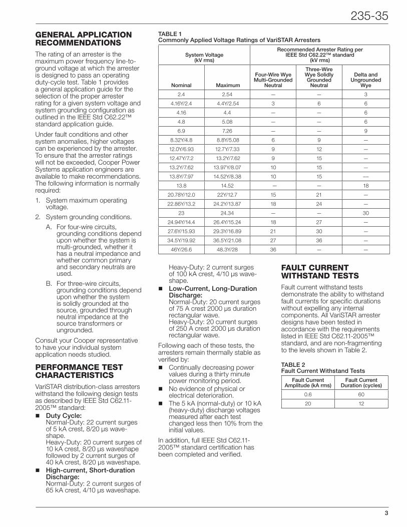
GEnErAl AppliCAtion rECommEnDAtionSThe rating of an arrester is the maximum power frequency line-to-ground voltage at which the arrester is designed to pass an operating duty-cycle test. Table 1 provides a general application guide for the selection of the proper arrester rating for a given system voltage and system grounding configuration as outlined in the IEEE Std C62.22™ standard application guide.
Under fault conditions and other system anomalies, higher voltages can be experienced by the arrester. To ensure that the arrester ratings will not be exceeded, Cooper Power Systems application engineers are available to make recommendations. The following information is normally required:
System maximum operating 1. voltage.
System grounding conditions.2.
For four-wire circuits, A. grounding conditions depend upon whether the system is multi-grounded, whether it has a neutral impedance and whether common primary and secondary neutrals are used.
For three-wire circuits, B. grounding conditions depend upon whether the system is solidly grounded at the source, grounded through neutral impedance at the source transformers or ungrounded.
Consult your Cooper representative to have your individual system application needs studied.
pErformAnCE tESt ChArACtEriStiCSVariSTAR distribution-class arresters withstand the following design tests as described by IEEE Std C62.11-2005™ standard:
Duty Cycle: �Normal-Duty: 22 current surges of 5 kA crest, 8/20 µs wave-shape. Heavy-Duty: 20 current surges of 10 kA crest, 8/20 µs waveshape followed by 2 current surges of 40 kA crest, 8/20 µs waveshape.High-current, Short-duration �Discharge: Normal-Duty: 2 current surges of 65 kA crest, 4/10 µs waveshape.
Heavy-Duty: 2 current surges of 100 kA crest, 4/10 µs wave-shape.Low-Current, Long-Duration �Discharge: Normal-Duty: 20 current surges of 75 A crest 2000 µs duration rectangular wave. Heavy-Duty: 20 current surges of 250 A crest 2000 µs duration rectangular wave.
Following each of these tests, the arresters remain thermally stable as verified by:
Continually decreasing power �values during a thirty minute power monitoring period.No evidence of physical or �electrical deterioration.The 5 kA (normal-duty) or 10 kA �(heavy-duty) discharge voltages measured after each test changed less then 10% from the initial values.
In addition, full IEEE Std C62.11-2005™ standard certification has been completed and verified.
fAult CurrEnt WithStAnD tEStSFault current withstand tests demonstrate the ability to withstand fault currents for specific durations without expelling any internal components. All VariSTAR arrester designs have been tested in accordance with the requirements listed in IEEE Std C62.11-2005™ standard, and are non-fragmenting to the levels shown in Table 2.
TABLE 1 Commonly Applied Voltage Ratings of VariSTAR Arresters
System Voltage (kV rms)
Recommended Arrester Rating per IEEE Std C62.22™ standard
(kV rms)
Nominal Maximum
Four-Wire Wye Multi-Grounded
Neutral
Three-Wire Wye Solidly Grounded
Neutral
Delta and Ungrounded
Wye
2.4 2.54 — — 3
4.16Y/2.4 4.4Y/2.54 3 6 6
4.16 4.4 — — 6
4.8 5.08 — — 6
6.9 7.26 — — 9
8.32Y/4.8 8.8Y/5.08 6 9 —
12.0Y/6.93 12.7Y/7.33 9 12 —
12.47Y/7.2 13.2Y/7.62 9 15 —
13.2Y/7.62 13.97Y/8.07 10 15 —
13.8Y/7.97 14.52Y/8.38 10 15 ––
13.8 14.52 — — 18
20.78Y/12.0 22Y/12.7 15 21 —
22.86Y/13.2 24.2Y/13.87 18 24 —
23 24.34 — — 30
24.94Y/14.4 26.4Y/15.24 18 27 —
27.6Y/15.93 29.3Y/16.89 21 30 —
34.5Y/19.92 36.5Y/21.08 27 36 —
46Y/26.6 48.3Y/28 36 — —
TABLE 2 Fault Current Withstand Tests
Fault Current Amplitude (kA rms)
Fault Current Duration (cycles)
0.6 60
20 12
4
UltraSIL Polymer-Housed VariSTAR Surge Arresters
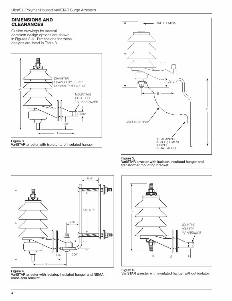
Figure 3.VariSTAR arrester with isolator and insulated hanger.
A
B
DIAMETER:HEAVY DUTY = 3.70"NORMAL DUTY = 3.40”
MOUNTING HOLE FOR 1/2" HARDWARE
0.56"
1.75"
Figure 5.VariSTAR arrester with isolator, insulated hanger and transformer mounting bracket.
Figure 6.VariSTAR arrester with insulated hanger without isolator.
C
B
MOUNTING HOLE FOR 1/2" HARDWARE
Figure 4.VariSTAR arrester with isolator, insulated hanger and NEMA cross-arm bracket.
A
0.56"
2.56"
1.7"
4.12"-5.15"
B
0"-4"
1.75"
DimEnSionS AnD ClEArAnCESOutline drawings for several common design options are shown in Figures 3-6. Dimensions for these designs are listed in Table 3.
GROUND STRAP
LINE TERMINAL
RESTRAINING DEVICE (REMOVE DURING INSTALLATION)
D
A
B
1.75"
235-35
5
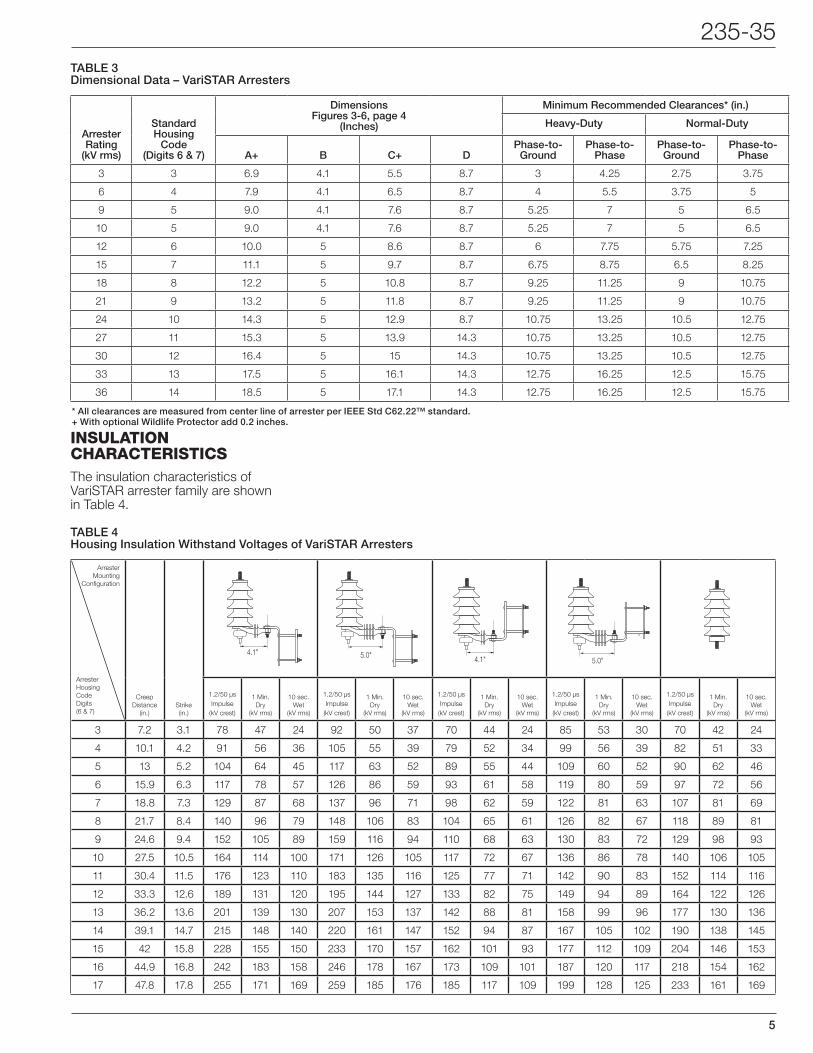
TABLE 3 Dimensional Data – VariSTAR Arresters
TABLE 4Housing Insulation Withstand Voltages of VariSTAR Arresters
inSulAtion ChArACtEriStiCSThe insulation characteristics of VariSTAR arrester family are shown in Table 4.
Arrester Rating
(kV rms)
Standard Housing
Code (Digits 6 & 7)
DimensionsFigures 3-6, page 4
(Inches)
Minimum Recommended Clearances* (in.)
Heavy-Duty Normal-Duty
A+ B C+ DPhase-to-
GroundPhase-to-
PhasePhase-to-
GroundPhase-to-
Phase
3 3 6.9 4.1 5.5 8.7 3 4.25 2.75 3.75
6 4 7.9 4.1 6.5 8.7 4 5.5 3.75 5
9 5 9.0 4.1 7.6 8.7 5.25 7 5 6.5
10 5 9.0 4.1 7.6 8.7 5.25 7 5 6.5
12 6 10.0 5 8.6 8.7 6 7.75 5.75 7.25
15 7 11.1 5 9.7 8.7 6.75 8.75 6.5 8.25
18 8 12.2 5 10.8 8.7 9.25 11.25 9 10.75
21 9 13.2 5 11.8 8.7 9.25 11.25 9 10.75
24 10 14.3 5 12.9 8.7 10.75 13.25 10.5 12.75
27 11 15.3 5 13.9 14.3 10.75 13.25 10.5 12.75
30 12 16.4 5 15 14.3 10.75 13.25 10.5 12.75
33 13 17.5 5 16.1 14.3 12.75 16.25 12.5 15.75
36 14 18.5 5 17.1 14.3 12.75 16.25 12.5 15.75
ArresterMounting
Configuration
ArresterHousingCodeDigits (6 & 7)
Creep Distance
(in.)Strike(in.)
4.1" 5.0" 4.1" 5.0"
1.2/50 µs Impulse
(kV crest)
1 Min. Dry
(kV rms)
10 sec.Wet
(kV rms)
1.2/50 µs Impulse
(kV crest)
1 Min. Dry
(kV rms)
10 sec.Wet
(kV rms)
1.2/50 µs Impulse
(kV crest)
1 Min. Dry
(kV rms)
10 sec.Wet
(kV rms)
1.2/50 µs Impulse
(kV crest)
1 Min. Dry
(kV rms)
10 sec.Wet
(kV rms)
1.2/50 µs Impulse
(kV crest)
1 Min. Dry
(kV rms)
10 sec.Wet
(kV rms)
3 7.2 3.1 78 47 24 92 50 37 70 44 24 85 53 30 70 42 24
4 10.1 4.2 91 56 36 105 55 39 79 52 34 99 56 39 82 51 33
5 13 5.2 104 64 45 117 63 52 89 55 44 109 60 52 90 62 46
6 15.9 6.3 117 78 57 126 86 59 93 61 58 119 80 59 97 72 56
7 18.8 7.3 129 87 68 137 96 71 98 62 59 122 81 63 107 81 69
8 21.7 8.4 140 96 79 148 106 83 104 65 61 126 82 67 118 89 81
9 24.6 9.4 152 105 89 159 116 94 110 68 63 130 83 72 129 98 93
10 27.5 10.5 164 114 100 171 126 105 117 72 67 136 86 78 140 106 105
11 30.4 11.5 176 123 110 183 135 116 125 77 71 142 90 83 152 114 116
12 33.3 12.6 189 131 120 195 144 127 133 82 75 149 94 89 164 122 126
13 36.2 13.6 201 139 130 207 153 137 142 88 81 158 99 96 177 130 136
14 39.1 14.7 215 148 140 220 161 147 152 94 87 167 105 102 190 138 145
15 42 15.8 228 155 150 233 170 157 162 101 93 177 112 109 204 146 153
16 44.9 16.8 242 183 158 246 178 167 173 109 101 187 120 117 218 154 162
17 47.8 17.8 255 171 169 259 185 176 185 117 109 199 128 125 233 161 169
* All clearances are measured from center line of arrester per IEEE Std C62.22™ standard.+ With optional Wildlife Protector add 0.2 inches.
6
UltraSIL Polymer-Housed VariSTAR Surge Arresters
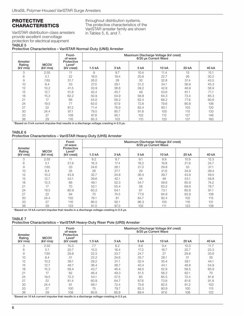
protECtivE ChArACtEriStiCSVariSTAR distribution-class arresters provide excellent overvoltage protection for electrical equipment
throughout distribution systems. The protective characteristics of the VariSTAR arrester family are shown in Tables 5, 6, and 7.
TABLE 5Protective Characteristics – VariSTAR Normal-Duty (UNS) Arrester
Arrester Rating
(kV rms)MCOV
(kV rms)
Front-of-wave
Protective Level*
(kV crest)
Maximum Discharge Voltage (kV crest) 8/20 µs Current Wave
1.5 kA 3 kA 5 kA 10 kA 20 kA 40 kA3 2.55 11 9 9.7 10.4 11.4 13 15.16 5.1 22 18.0 19.4 20.8 22.7 26 30.29 7.65 31.7 26.0 28 30 32.8 37.4 43.510 8.4 33 27.0 29.1 31.2 34.1 38.9 45.312 10.2 41.5 33.9 36.6 39.2 42.9 48.9 56.915 12.7 51.8 42.4 45.7 49 53.6 61.1 71.118 15.3 62.2 50.9 54.9 58.8 64.3 73.4 85.321 17 66 54.0 58.2 62.4 68.2 77.9 90.624 19.5 77 63.0 67.9 72.8 79.6 90.8 10627 22 87.2 71.4 76.9 82.4 90.1 103 12030 24.4 97.1 79.5 85.7 91.8 100 115 13333 27 108 87.8 95.1 102 112 127 14836 29 116 95.3 103 110 120 137 160
*Based on 5 kA current impulse that results in a discharge voltage cresting in 0.5 µs.
TABLE 6Protective Characteristics – VariSTAR Heavy-Duty (UHS) Arrester
Arrester Rating
(kV rms)MCOV
(kV rms)
Front-of-wave
Protective Level*
(kV crest)
Maximum Discharge Voltage (kV crest) 8/20 µs Current Wave
1.5 kA 3 kA 5 kA 10 kA 20 kA 40 kA3 2.55 11 8.2 8.7 9.1 9.9 10.9 12.36 5.1 21.9 16.3 17.4 18.2 19.8 21.9 24.79 7.65 33 24.6 26.1 27.3 29.8 33 37.110 8.4 35 26 27.7 29 31.6 34.9 39.412 10.2 43.9 32.7 34.8 36.4 39.7 43.9 49.515 12.7 53.1 39.6 42.1 44 48 53.1 59.818 15.3 66 49.1 52.3 54.7 59.6 65.9 74.221 17 70 52.1 55.4 58 63.2 69.9 78.724 19.5 80.9 60.2 64.1 67 73.1 80.8 91.127 22 94 70 74.5 77.9 84.9 93.9 10630 24.4 102 76.1 81 84.7 92.4 102 11533 27 116 86.5 92.1 96.3 105 116 13136 29 123 91.5 97.3 102 111 123 138
*Based on 10 kA current impulse that results in a discharge voltage cresting in 0.5 µs.
TABLE 7Protective Characteristics – VariSTAR Heavy-Duty Riser Pole (URS) Arrester
Arrester Rating
(kV rms)MCOV
(kV rms)
Front-of-wave
Protective Level*
(kV crest)
Maximum Discharge Voltage (kV crest) 8/20 µs Current Wave
1.5 kA 3 kA 5 kA 10 kA 20 kA 40 kA3 2.55 10.3 7.7 8.2 8.6 9.4 10.3 11.76 5.1 20.7 15.5 16.4 17.2 18.7 20.7 23.39 7.65 29.8 22.3 23.7 24.7 27 29.8 33.610 8.4 31 23.2 24.6 25.7 28.1 31 3512 10.2 39.1 29.2 31.1 32.4 35.4 39.1 44.115 12.7 48.7 36.4 38.7 40.4 44.1 48.8 54.918 15.3 58.4 43.7 46.4 48.5 52.9 58.5 65.921 17 62 46.4 49.3 51.5 56.2 62.1 7024 19.5 72.3 54.1 57.5 60 65.5 72.4 81.627 22 81.4 60.9 64.7 67.6 73.8 81.6 91.930 24.4 91 68.1 72.4 75.6 82.5 91.2 10333 27 100 75 79.7 83.3 90.9 100 11336 29 108 80.6 85.6 89.4 97.6 108 122
*Based on 10 kA current impulse that results in a discharge voltage cresting in 0.5 µs.
235-35
7
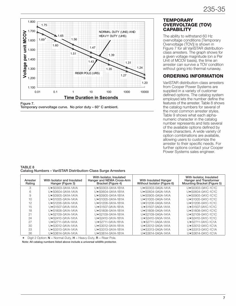
Figure 7.Temporary overvoltage curve. No prior duty – 60° C ambient.
1.67
1.60
1.51
1.43
1.35
1.20
1.241.31
1.39
1.47
1.561.65
1.75
1.69
1.27
1.100
1.200
1.300
1.400
1.500
1.600
1.700
1.800
0.01 0.1 1 10 100 1000 10000
Time Duration in Seconds
Volta
ge p
er u
nit M
CO
V
RISER POLE (URS)
NORMAL DUTY (UNS) AND HEAVY DUTY (UHS)
tEmporAry ovErvoltAGE (tov) CApAbilityThe ability to withstand 60 Hz overvoltage conditions [Temporary Overvoltage (TOV)] is shown in Figure 7 for all VariSTAR distribution-class arresters. The graph shows for a given voltage magnitude (on a Per Unit of MCOV basis), the time an arrester can survive a TOV condition without going into thermal runaway.
orDErinG informAtionVariSTAR distribution-class arresters from Cooper Power Systems are supplied in a variety of customer defined options. The catalog system employed lets the number define the features of the arrester. Table 8 shows the catalog numbers for several of the most common arrester styles. Table 9 shows what each alpha-numeric character in the catalog number represents and lists several of the available options defined by these characters. A wide variety of option combinations are available, allowing users to customize the arrester to their specific needs. For further options contact your Cooper Power Systems sales engineer.
TABLE 8 Catalog Numbers – VariSTAR Distribution-Class Surge Arresters
Arrester Rating
With Isolator and Insulated Hanger (Figure 3)
With Isolator, Insulated Hanger and NEMA Cross-Arm
Bracket (Figure 4)With Insulated Hanger
Without Isolator (Figure 6)
With Isolator, Insulated Hanger and Transformer
Mounting Bracket (Figure 5)3 U«S0303-0A1A-1A1A U«S0303-0A1A-1B1A U«S0303-0A0A-1A1A U«S0303-0A1C-1C1C6 U«S0604-0A1A-1A1A U«S0604-0A1A-1B1A U«S0604-0A0A-1A1A U«S0604-0A1C-1C1C9 U«S0905-0A1A-1A1A U«S0905-0A1A-1B1A U«S0905-0A0A-1A1A U«S0905-0A1C-1C1C10 U«S1005-0A1A-1A1A U«S1005-0A1A-1B1A U«S1005-0A0A-1A1A U«S1005-0A1C-1C1C12 U«S1206-0A1A-1A1A U«S1206-0A1A-1B1A U«S1206-0A0A-1A1A U«S1206-0A1C-1C1C15 U«S1507-0A1A-1A1A U«S1507-0A1A-1B1A U«S1507-0A0A-1A1A U«S1507-0A1C-1C1C18 U«S1808-0A1A-1A1A U«S1808-0A1A-1B1A U«S1808-0A0A-1A1A U«S1808-0A1C-1C1C21 U«S2109-0A1A-1A1A U«S2109-0A1A-1B1A U«S2109-0A0A-1A1A U«S2109-0A1C-1C1C24 U«S2410-0A1A-1A1A U«S2410-0A1A-1B1A U«S2410-0A0A-1A1A U«S2410-0A1C-1C1C27 U«S2711-0A1A-1A1A U«S2711-0A1A-1B1A U«S2711-0A0A-1A1A U«S2711-0A1C-1C1A30 U«S3012-0A1A-1A1A U«S3012-0A1A-1B1A U«S3012-0A0A-1A1A U«S3012-0A1C-1C1A33 U«S3313-0A1A-1A1A U«S3313-0A1A-1B1A U«S3313-0A0A-1A1A U«S3313-0A1C-1C1A36 U«S3614-0A1A-1A1A U«S3614-0A1A-1B1A U«S3614-0A0A-1A1A U«S3614-0A1C-1C1A
« Digit 2 Option: N = Normal-Duty, H = Heavy-Duty, R = Riser Pole.Note: All catalog numbers listed above include a universal wildlife protector.
8
UltraSIL Polymer-Housed VariSTAR Surge Arresters
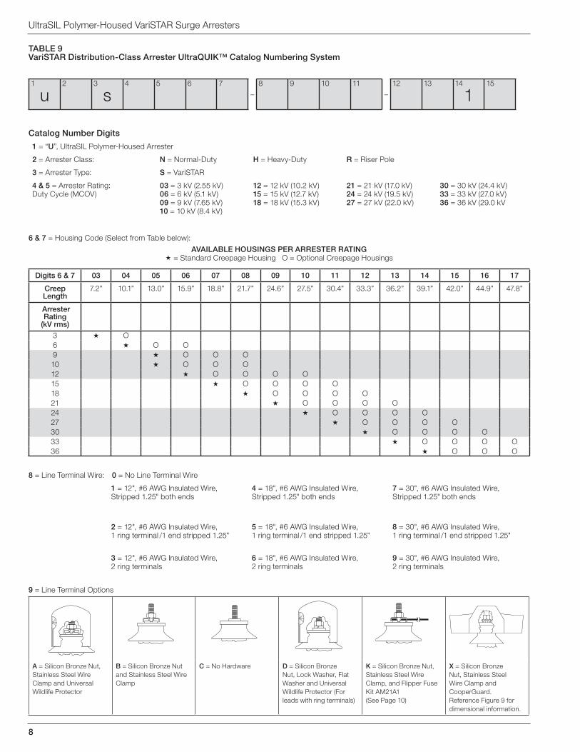
8 = Line Terminal Wire: 0 = No Line Terminal Wire
1 = 12", #6 AWG Insulated Wire, Stripped 1.25" both ends
4 = 18", #6 AWG Insulated Wire, Stripped 1.25" both ends
7 = 30", #6 AWG Insulated Wire,Stripped 1.25" both ends
2 = 12", #6 AWG Insulated Wire, 1 ring terminal /1 end stripped 1.25"
5 = 18", #6 AWG Insulated Wire, 1 ring terminal /1 end stripped 1.25"
8 = 30", #6 AWG Insulated Wire, 1 ring terminal /1 end stripped 1.25"
3 = 12", #6 AWG Insulated Wire, 2 ring terminals
6 = 18", #6 AWG Insulated Wire,2 ring terminals
9 = 30", #6 AWG Insulated Wire, 2 ring terminals
TABLE 9VariSTAR Distribution-Class Arrester UltraQUIK™ Catalog Numbering System
Catalog Number Digits
1 = “U”, UltraSIL Polymer-Housed Arrester
2 = Arrester Class: N = Normal-Duty H = Heavy-Duty R = Riser Pole
3 = Arrester Type: S = VariSTAR
4 & 5 = Arrester Rating: Duty Cycle (MCOV)
03 = 3 kV (2.55 kV) 06 = 6 kV (5.1 kV)09 = 9 kV (7.65 kV) 10 = 10 kV (8.4 kV)
12 = 12 kV (10.2 kV) 15 = 15 kV (12.7 kV)18 = 18 kV (15.3 kV)
21 = 21 kV (17.0 kV)24 = 24 kV (19.5 kV)27 = 27 kV (22.0 kV)
30 = 30 kV (24.4 kV)33 = 33 kV (27.0 kV)36 = 36 kV (29.0 kV
9 = Line Terminal Options
A = Silicon Bronze Nut, Stainless Steel Wire Clamp and Universal Wildlife Protector
B = Silicon Bronze Nut and Stainless Steel Wire Clamp
C = No Hardware D = Silicon Bronze Nut, Lock Washer, Flat Washer and Universal Wildlife Protector (For leads with ring terminals)
K = Silicon Bronze Nut, Stainless Steel Wire Clamp, and Flipper Fuse Kit AM21A1 (See Page 10)
X = Silicon Bronze Nut, Stainless Steel Wire Clamp and CooperGuard. Reference Figure 9 for dimensional information.
Digits 6 & 7 03 04 05 06 07 08 09 10 11 12 13 14 15 16 17
Creep Length
7.2” 10.1” 13.0” 15.9” 18.8” 21.7” 24.6” 27.5” 30.4” 33.3” 36.2” 39.1” 42.0” 44.9” 47.8”
Arrester Rating
(kV rms)3 « O6 « O O9 « O O O10 « O O O12 « O O O O15 « O O O O18 « O O O O21 « O O O O24 « O O O O27 « O O O O30 « O O O O33 « O O O O36 « O O O
6 & 7 = Housing Code (Select from Table below):
AVAILABLE HOUSINGS PER ARRESTER RATING« = Standard Creepage Housing O = Optional Creepage Housings
1
u2 3
s4 5 6 7
–8 9 10 11
–12 13 14
115
235-35
9
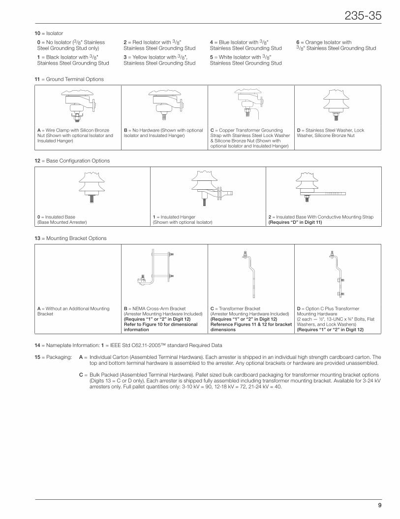
10 = Isolator
0 = No Isolator (3/8" StainlessSteel Grounding Stud only)
2 = Red Isolator with 3/8"Stainless Steel Grounding Stud
4 = Blue Isolator with 3/8"Stainless Steel Grounding Stud
6 = Orange Isolator with3/8" Stainless Steel Grounding Stud
1 = Black Isolator with 3/8"Stainless Steel Grounding Stud
3 = Yellow Isolator with 3/8", Stainless Steel Grounding Stud
5 = White Isolator with 3/8"Stainless Steel Grounding Stud
14 = Nameplate Information: 1 = IEEE Std C62.11-2005™ standard Required Data
15 = Packaging: A = Individual Carton (Assembled Terminal Hardware). Each arrester is shipped in an individual high strength cardboard carton. The top and bottom terminal hardware is assembled to the arrester. Any optional brackets or hardware are provided unassembled.
C = Bulk Packed (Assembled Terminal Hardware). Pallet sized bulk cardboard packaging for transformer mounting bracket options (Digits 13 = C or D only). Each arrester is shipped fully assembled including transformer mounting bracket. Available for 3-24 kV arresters only. Full pallet quantities only: 3-10 kV = 90, 12-18 kV = 72, 21-24 kV = 40.
11 = Ground Terminal Options
A = Wire Clamp with Silicon Bronze Nut (Shown with optional Isolator and Insulated Hanger)
B = No Hardware (Shown with optional Isolator and Insulated Hanger)
C = Copper Transformer Grounding Strap with Stainless Steel Lock Washer & Silicone Bronze Nut (Shown with optional Isolator and Insulated Hanger)
D = Stainless Steel Washer, Lock Washer, Silicone Bronze Nut
13 = Mounting Bracket Options
A = Without an Additional Mounting Bracket
B = NEMA Cross-Arm Bracket (Arrester Mounting Hardware Included) (Requires “1” or “2” in Digit 12) Refer to Figure 10 for dimensional information
C = Transformer Bracket(Arrester Mounting Hardware Included)(Requires “1” or “2” in Digit 12)Reference Figures 11 & 12 for bracket dimensions
D = Option C Plus Transformer Mounting Hardware(2 each — 1/2", 13-UNC x 3/4" Bolts, Flat Washers, and Lock Washers)(Requires “1” or “2” in Digit 12)
12 = Base Configuration Options
0 = Insulated Base(Base Mounted Arrester)
1 = Insulated Hanger(Shown with optional Isolator)
2 = Insulated Base With Conductive Mounting Strap(Requires “D” in Digit 11)
10
UltraSIL Polymer-Housed VariSTAR Surge Arresters
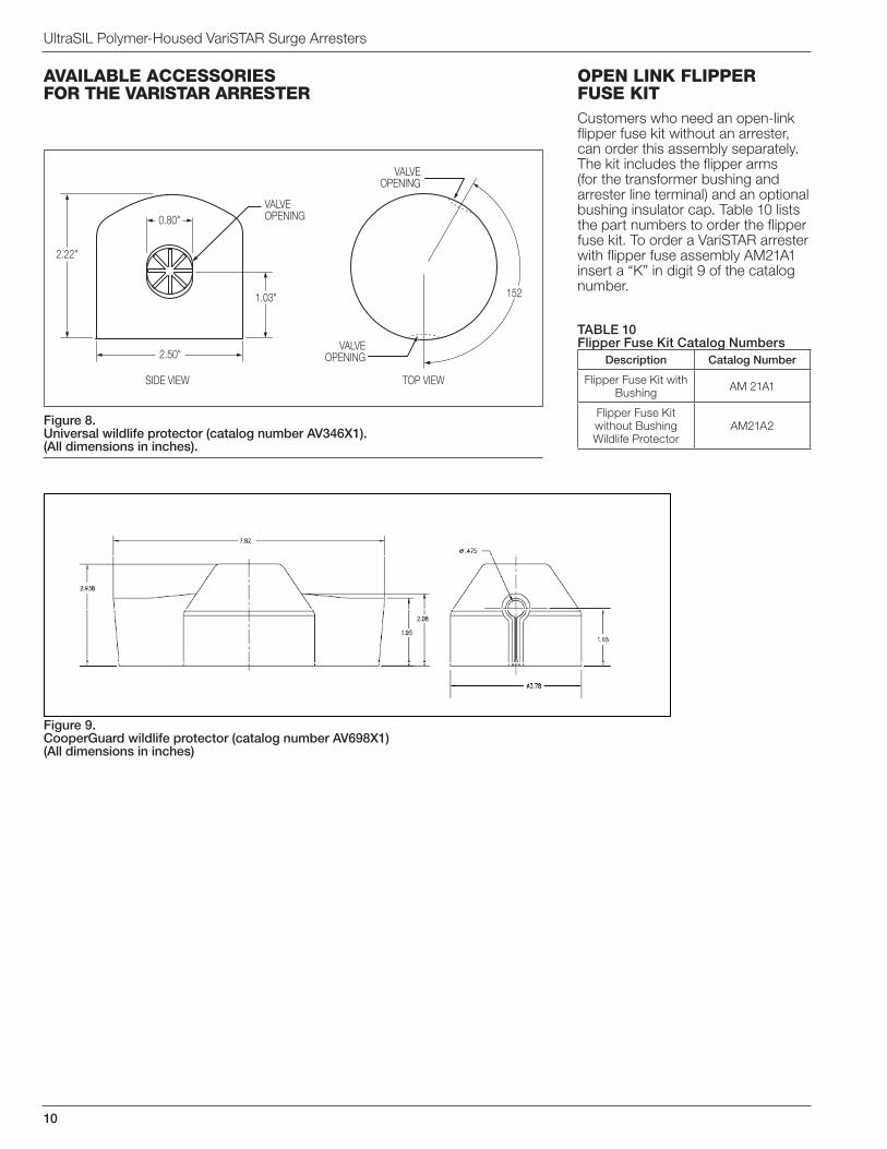
Figure 8. Universal wildlife protector (catalog number AV346X1). (All dimensions in inches).
AvAilAblE ACCESSoriES for thE vAriStAr ArrEStEr
opEn link flippEr fuSE kitCustomers who need an open-link flipper fuse kit without an arrester, can order this assembly separately. The kit includes the flipper arms (for the transformer bushing and arrester line terminal) and an optional bushing insulator cap. Table 10 lists the part numbers to order the flipper fuse kit. To order a VariSTAR arrester with flipper fuse assembly AM21A1 insert a “K” in digit 9 of the catalog number.
0.80"
2.50"
1.03"
2.22"
VALVEOPENING
VALVEOPENING
VALVEOPENING
SIDE VIEW TOP VIEW
152
TABLE 10Flipper Fuse Kit Catalog Numbers
Description Catalog Number
Flipper Fuse Kit with Bushing AM 21A1
Flipper Fuse Kit without Bushing Wildlife Protector
AM21A2
Figure 9. CooperGuard wildlife protector (catalog number AV698X1)(All dimensions in inches)
235-35
11
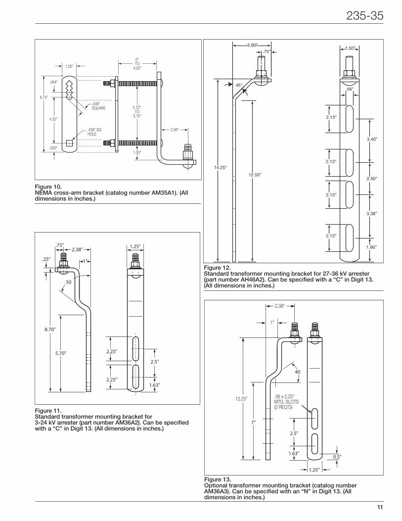
Figure 10. NEMA cross-arm bracket (catalog number AM35A1). (All dimensions in inches.)
0"TO
4.00"
4.12" TO
5.15"
6.75"
2.56"
4.50"
.344"
1.25"
.438"SQUARE
.438" SQ.HOLE
.500"1.50"
Figure 11.Standard transformer mounting bracket for 3-24 kV arrester (part number AM36A2). Can be specified with a “C” in Digit 13. (All dimensions in inches.)
2.38"
.25"
.75"
1"
8.70"
5.70"
1.63"
2.25"
50
2.5"
2.25"
1.25"
Figure 12. Standard transformer mounting bracket for 27-36 kV arrester (part number AH46A2). Can be specified with a “C” in Digit 13. (All dimensions in inches.)
3.00”.75”
45°
14.25”
12.55”
2.13”
2.13”
2.13”
2.13”
.56”
3.40”
2.50”
3.38”
1.86”
1.50”
Figure 13. Optional transformer mounting bracket (catalog number AM36A3). Can be specified with an “N” in Digit 13. (All dimensions in inches.)
2.38"
1"
12.25"
7"
1.63"
2.5"
40
0.5"
.56 x 2.25"MTG. SLOTS(2 REQ'D)
1.25"
©2012 Cooper Industries. All Rights Reserved.Cooper Power Systems, VariSTAR, UltraSIL, UltraQUIK, and CooperGuard are valuable trademarks of Cooper Industries in the U.S. and other countries. You are not permitted to use the Cooper Trademarks without the prior written consent of Cooper Industries.
IEEE Std C62.11-2004™ standard and IEEE Std C62.22™ standard are trademarks of the Institute of Electrical and Electronics Engineers, Inc.IEEE is a registered trademark of the Institute of Electrical and Electronics Engineers, Inc., (IEEE). This publication/product is not endorsed or approved by the IEEE.
One Cooper | www.cooperpower.com | Online2300 Badger DriveWaukesha, WI 53188 USA
UltraSIL Polymer-Housed VariSTAR Surge Arresters
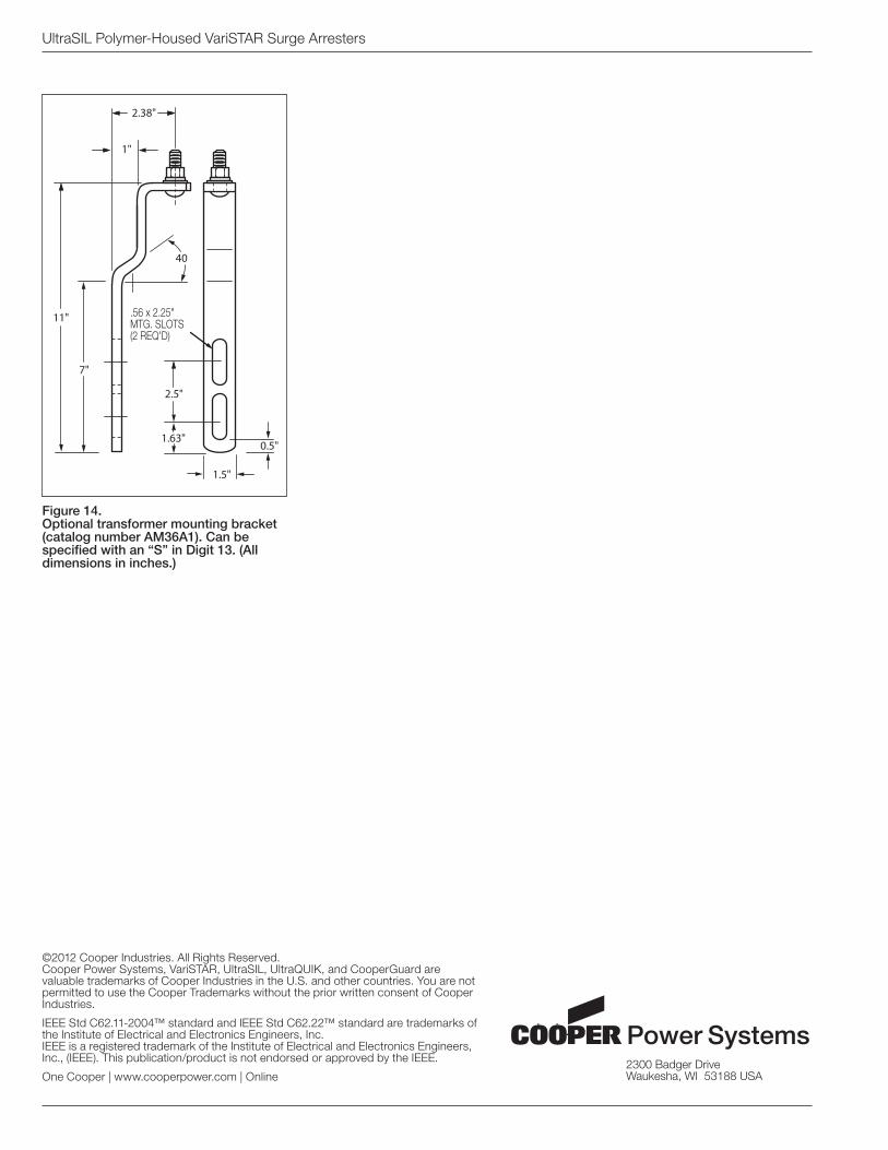
Figure 14. Optional transformer mounting bracket (catalog number AM36A1). Can be specified with an “S” in Digit 13. (All dimensions in inches.)
2.38"
1"
11"
7"
1.63"
2.5"
40
0.5"
.56 x 2.25"MTG. SLOTS(2 REQ'D)
1.5"