Embed Size (px)
Citation preview
CAUTION! All accessories, switches, climate controls panels, and especially air bag indicator lights must be connected before cycling the ignition. Also, do not remove the factory radio with the key in the on position, or while the vehicle is running.
Metra. The World’s Best Kits.® MetraOnline.com © COPYRIGHT 2018 METRA ELECTRONICS CORPORATION REV. 1/5/18 INST99-9721
I N S TA L L AT I O N I N S T R U C T I O N S99-9721
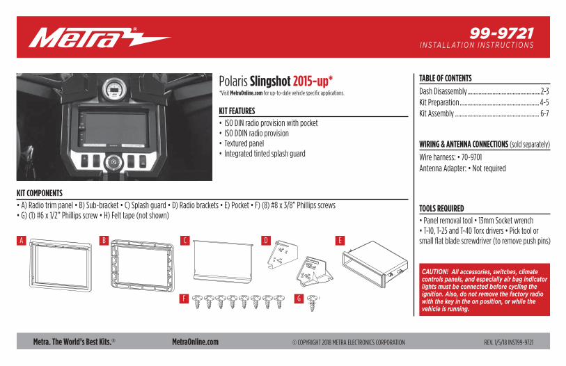
KIT FEATURES• ISO DIN radio provision with pocket• ISO DDIN radio provision• Textured panel• Integrated tinted splash guard
KIT COMPONENTS• A) Radio trim panel • B) Sub-bracket • C) Splash guard • D) Radio brackets • E) Pocket • F) (8) #8 x 3/8” Phillips screws • G) (1) #6 x 1/2” Phillips screw • H) Felt tape (not shown)
TOOLS REQUIRED• Panel removal tool • 13mm Socket wrench • T-10, T-25 and T-40 Torx drivers • Pick tool or small flat blade screwdriver (to remove push pins)
TABLE OF CONTENTS
Dash Disassembly ...............................................2-3Kit Preparation ................................................... 4-5Kit Assembly ...................................................... 6-7
WIRING & ANTENNA CONNECTIONS (sold separately)
Wire harness: • 70-9701 Antenna Adapter: • Not required
A B C D E
F G
Polaris Slingshot 2015-up**Visit MetraOnline.com for up-to-date vehicle specific applications.
1.800.221.0932 | MetraOnline.com2
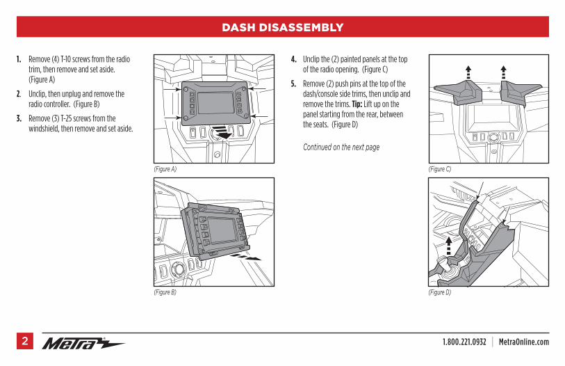
1. Remove (4) T-10 screws from the radio trim, then remove and set aside. (Figure A)
2. Unclip, then unplug and remove the radio controller. (Figure B)
3. Remove (3) T-25 screws from the windshield, then remove and set aside.
4. Unclip the (2) painted panels at the top of the radio opening. (Figure C)
5. Remove (2) push pins at the top of the dash/console side trims, then unclip and remove the trims. Tip: Lift up on the panel starting from the rear, between the seats. (Figure D)
Continuedonthenextpage
DASH DISASSEMBLY
(FigureB)
(FigureA) (FigureC)
(FigureD)
REV. 1/5/2018 INST99-9721 3
DASH DISASSEMBLY (CONT.)
(FigureE)
(FigureF)
(FigureG)
(FigureH)
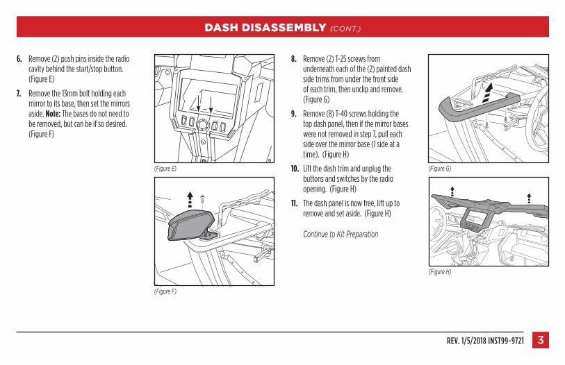
6. Remove (2) push pins inside the radio cavity behind the start/stop button. (Figure E)
7. Remove the 13mm bolt holding each mirror to its base, then set the mirrors aside. Note: The bases do not need to be removed, but can be if so desired. (Figure F)
8. Remove (2) T-25 screws from underneath each of the (2) painted dash side trims from under the front side of each trim, then unclip and remove. (Figure G)
9. Remove (8) T-40 screws holding the top dash panel, then if the mirror bases were not removed in step 7, pull each side over the mirror base (1 side at a time). (Figure H)
10. Lift the dash trim and unplug the buttons and switches by the radio opening. (Figure H)
11. The dash panel is now free, lift up to remove and set aside. (Figure H)
ContinuetoKitPreparation
1.800.221.0932 | MetraOnline.com4
(FigureA) (FigureC)(FigureB)
KIT PREPARATION
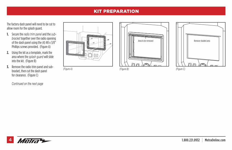
The factory dash panel will need to be cut to allow room for the splash guard.
1. Secure the radiotrimpanel and the sub-bracket together over the radio opening of the dash panel using the (4) #8 x 3/8” Phillips screws provided. (Figure A)
2. Using the kit as a template, mark the area where the splashguardwill slide into the kit. (Figure B)
3. Remove the radio trim panel and sub-bracket, then cut the dash panel for clearance. (Figure C)
Continuedonthenextpage
Remove shaded areaArea to be removed
REV. 1/5/2018 INST99-9721 5
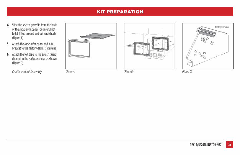
4. Slide the splashguardin from the back of the radiotrimpanel (be careful not to let it flop around and get scratched). (Figure A)
5. Attach the radiotrimpanel and sub-bracket to the factory dash. (Figure B)
6. Attach the felt tape to the splash guard channel in the radiobrackets as shown. (Figure C)
ContinuetoKitAssembly
KIT PREPARATION
(FigureA) (FigureB) (FigureC)
Felt tape location
1.800.221.0932 | MetraOnline.com6
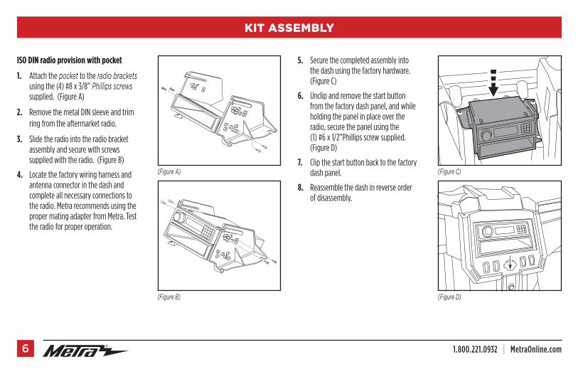
ISO DIN radio provision with pocket
1. Attach the pocket to the radiobrackets using the (4) #8 x 3/8” Phillipsscrews supplied. (Figure A)
2. Remove the metal DIN sleeve and trim ring from the aftermarket radio.
3. Slide the radio into the radio bracket assembly and secure with screws supplied with the radio. (Figure B)
4. Locate the factory wiring harness and antenna connector in the dash and complete all necessary connections to the radio. Metra recommends using the proper mating adapter from Metra. Test the radio for proper operation.
5. Secure the completed assembly into the dash using the factory hardware. (Figure C)
6. Unclip and remove the start button from the factory dash panel, and while holding the panel in place over the radio, secure the panel using the (1) #6 x 1/2”Phillips screw supplied. (Figure D)
7. Clip the start button back to the factory dash panel.
8. Reassemble the dash in reverse order of disassembly.
(FigureC)(FigureA)
(FigureD)(FigureB)
KIT ASSEMBLY
REV. 1/5/2018 INST99-9721 7
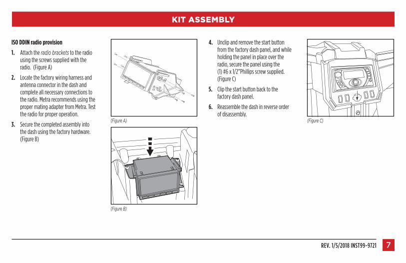
ISO DDIN radio provision
1. Attach the radiobrackets to the radio using the screws supplied with the radio. (Figure A)
2. Locate the factory wiring harness and antenna connector in the dash and complete all necessary connections to the radio. Metra recommends using the proper mating adapter from Metra. Test the radio for proper operation.
3. Secure the completed assembly into the dash using the factory hardware. (Figure B)
4. Unclip and remove the start button from the factory dash panel, and while holding the panel in place over the radio, secure the panel using the (1) #6 x 1/2”Phillips screw supplied. (Figure C)
5. Clip the start button back to the factory dash panel.
6. Reassemble the dash in reverse order of disassembly.
(FigureC)(FigureA)
(FigureB)
KIT ASSEMBLY
KNOWLEDGE IS POWEREnhance your installation and fabrication skills by enrolling in the most recognized and respected mobile electronics school in our industry.Log onto www.installerinstitute.com or call 800-354-6782 for more information and take steps toward a better tomorrow.
®
Metra recommends MECP certified technicians
IMPORTANTIf you are having difficulties with the installation of this product, please call our Tech Support line at 1-800-253-TECH. Before doing so, look over the instructions a second time, and make sure the installation was performed exactly as the instructions are stated. Please have the vehicle apart and ready to perform troubleshooting steps before calling.
Metra. The World’s Best Kits.® MetraOnline.com © COPYRIGHT 2018 METRA ELECTRONICS CORPORATION REV. 1/5/18 INST99-9721
I N S TA L L AT I O N I N S T R U C T I O N S99-9721