Embed Size (px)
Citation preview
SECTION 23 09 93 SEQUENCE OF OPERATIONS FOR HVAC CONTROLS
13-032 23 09 93 - 1
PART 1 - GENERAL
1.1 SUMMARY
A. This Section includes control sequences for HVAC systems, subsystems, and other equipment.
B. See Division 23 Section "230923 Direct Digital Control Systems for HVAC" for control equipment and devices and for submittal requirements.
1.2 SUBMITTALS
A. Submittals are required and shall include detailed descriptions of the proposed sequence of operations for all systems specific to the project.
B. The following information shall be submitted as a very minimum to the Engineer:
1. System diagrams denoting the operation of each individual system, folded to an equivalent 8-1/2 inch by 11 inch bound packet.
2. DDC logic diagrams. 3. Written sequences of operation with each specific diagram.
1.3 GENERAL
A. The DDC system shall utilize the existing Automated Logic server located at the exisitng High School (connected to the Norton School System Ethernet), where all software, graphics, alarms, and trends shall reside. The DDC System communication protocol shall be BACnet where indicated on the drawings, and MODBUS where indicated on the drawings. The communication protocol between a VAV Box controller and room temp sensor or room combination temp/CO2 sensor or room combination temp/relative/relative humidity/CO2 sensor can be the DDC system communication standard protocol as long as the communication speed is sufficient to perform all functions described in the Sequence of Operations in a stable manner and must be demonstrated to the satisfaction of the Architect/Engineer.
B. DDC System Contractor shall provide temperature differentials and time delays as required to maintain systems stability.
C. All Analog Inputs, Analog Outputs, Binary Inputs and Binary Outputs shall be capable of being manually overridden through the graphic display that shows these types of points, and, the graphic display shall display the point has been manually overridden by either changing the color of the point or having text next to the point that states “manually overridden”.
D. DDC system shall be capable of providing alarms of any point within the system. The DDC system shall be capable of trending any point within the system, including software control points calculated by the DDC System, example, heating hot water supply temperature control point that was calculated based on an outdoor air temperature reset schedule..
E. Each graphic display that contains an outdoor air airflow rate shall show the following; outdoor air airflow control point, outdoor air airflow, and shall include on the graphic display; design outdoor air airflow setpoint. Design outdoor air airflow setpoint is defined as the values shown on Drawing M701 within the Air Handling Unit Equipment Schedule. If AHU has CO2 demand control ventilation, design outdoor air airflow setpoint tag shall include value shown on Drawing M701 and the reduced value described herein.
23 09 93.01 – SEQUENCE OF OPERATIONS FOR HVAC CONTROLS
23 09 93 - 2 13-032
F. For each graphic display that contains a variable frequency drive (VFD) speed control point, the “speed feedback” value shall also be displayed. This is show the DDC system commanded speed compared to the actual VFD speed. Speed shall be displayed as percent (%) maximum motor speed. Graphic display shall include the VFD minimum speed that has been programmed into the VFD. Example; VFD has been programmed for minimum speed of 25% to maximum speed of 100%, if graphic display is displaying calculated control point is 10% speed, feedback will display 25% and operator will know that VFD has been programmed for a minimum speed of 25%.
G. All graphic displays that contain a Variable Frequency Drive (VFD), shall include a display of each VFD with a “hot spot” over said VFD that when hit with the mouse shall go to a text screen showing the information obtained from the VFD from the BACnet communication. DDC System Contractor shall provide a list of all points that can be displayed through the communication link to Norton School, and then Norton School shall determine which points are to be displayed. Each display, graphic display, or text display, shall include the associated Room Name, Room Number and Equipment Number. Room Name and Room Number shall be same as displayed at each room, that is, they shall match the installed Room Labels. Equipment Number shall match those shown on the drawings.
H. Run Time Accumulation - A re-settable run time accumulation for each Binary Output Object connected to mechanical loads greater than 1 HP, electrical loads greater than 10 KW, or wherever else specified or requested by Norton school shall be provided.
I. DDC System Graphics shall consist as a minimum of :
1. Cover Graphic Display showing entire floor plan, with hot spots over descriptions to move to floor plans, heating hot water plant, chilled water plant or the displays screens described below.
2. The first floor plan shall show the entire first and second floor with hot spots to move to individual floor plans that match the drawing floor plans, and each floor plan shall display the room temperature, room relative humidity, CO2 level, status of lighting control occupancy sensor as “occupied or unoccupied”, and has a “hot spot” at the room temperature or room relative humidity or CO2 level such that the cursor can be brought to this “hot spot” and then the graphic display of the FPVAV or VAV box is then displayed.
3. Display of the heating hot water plant.
4. Display of the chilled water plant.
5. Display of each Air Handling Unit, 9 graphic displays, and, all sub-displays (text screens) described herein. Each display shall include the status of the duct smoke detector, and is obtained via the BACnet communication to the Fire alarm Panel. Each display shall also include an “off-automatic” point so that Norton Maintenance can easily stop the unit.
6. Display of each single duct shutoff type VAV box.
7. Display showing all Desrtatification fans, one display for all Destratification fans.
8. Display of cabinet unit heaters, one display for all cabinet unit heaters.
9. Display of status of all exhaust fans (one or two simple display for all fans) controlled and/or monitored by the DDC system.
10. Display of Cross-Connect Room Temperature, Kitchen Freezer and Kitchen Cooler temperature, all Technology Closet Room Temperature (quantity 6) and Elevator Machine Temperature (quantity 2).
11. Display of Electricity Meter data, include status of surge protector alarm, and all sub-displays (text screens) described herein.
12. Display of main Domestic Water Meter data
23 09 93.01 – SEQUENCE OF OPERATIONS FOR HVAC CONTROLS
13-032 23 09 93 - 3
13. Display of Natural Gas Meter data
14. Display of Domestic Hot Water supply temperature, domestic hot water heaters, recirc pumps, domestic hot water meter, and all sub-displays (text screens) described herein.
15. Display of Domestic Water Booster Pump.
16. Display of Emergency Generator
17. Display of Fire Alarm System.
18. Display for Scheduling “Snow Day” or “Delay Start of School”.
19. Display showing all current unacknowledged alarms and past unacknowledged alarms.
20. Provide screens displaying the written out full sequence of operation for each piece of HVAC equipment. Provide a link to the sequence of operation displays on their respective equipment graphics.
1.4 HEATING HOT WATER BOILERS AND ASSOCIATED PUMPS
A. The heating hot water boiler system consists of two heating hot water boilers and two circulating pumps (lead/standby)
B. One heating hot water pump shall be designated, through the DDC System, as the lead pump (adj.) and other shall be the standby pump. The standby pump shall automatically start on a lead pump failure. The DDC system shall rotate the lead pump and standby pump on a weekly (adj.) basis.
C. The DDC System shall enable and disable each boiler and control the firing rate of each boiler. Each boiler controller communicates with the DDC System via MODBUS communication protocol. One heating hot boiler shall be designated as the lead boiler (adj.) and other shall then be the lag boiler. The lag boiler shall automatically start on a lead boiler failure, and the lag boiler shall also operate when the DDC system requires two boilers to operate. The DDC system shall rotate the lead boiler and lag boiler on a weekly basis.
D. The DDC System, shall reset the boiler plant heating hot water discharge temperature setpoint, and each boiler controller shall control the operation of the boiler to maintain this setpoint. When the outdoor temperature is between 70F (adj) and 40F (adj), reset shall be based on outdoor air temperature, and shall be linear between setpoints and do not go below or above setpoint limits when the outdoor temperature is above or below the values in the reset schedule; 40F outdoors - 140F heating hot water supply temperature, 70F outdoors - 110F heating hot water supply temperature. When the outdoor air temperature is above 70F (adj), the heating hot water supply temperature shall be maintained at 110F (adj). When the outdoor air temperature is below 40F (adj), the heating hot water supply temperature shall be maintained at 140F (adj).
E. When the outdoor temperature is below 35F (adj.), the DDC system shall energize the lead hot water pump to run continuously and enable the boiler plant. When the outdoor temperature is below 55F (adj.) the DDC system shall energize the lead hot water pump to run continuously during occupied periods and during the heating optimal start period (see AHU sequence of operation) and enable the boiler plant. During unoccupied periods when the outdoor air temperature is above 35F (adj) the DDC system shall energize the lead hot water pump to run continuously and enable the boiler plant when there is a demand for heat from any heating coil (AHU, VAV Box, Cabinet Unit Heater, Etc) on the DDC system, and the pump and boiler plant shall be energized/enabled for a minimum 30 minute period. During occupied periods when the outdoor air temperature is above 55F the DDC system shall energize the lead hot water pump to run continuously and enable the boiler plant when there is a demand for heat from any heating coil (AHU, VAV Box, Cabinet Unit Heater, etc) on the DDC system, and the pump and boiler shall be energized/enabled for a minimum 30 minute period.

23 09 93.01 – SEQUENCE OF OPERATIONS FOR HVAC CONTROLS
23 09 93 - 4 13-032
F. When the lead boiler is energized by the DDC System, the DDC System shall open the boiler water isolation valve and the boiler shall not be allowed to be enabled until the boiler controller verifies proof of water flow through the boiler by the factor furnished and mounted flow switch located in the boiler water discharge pipe. When a lag boiler is enabled by the DDC System, the DDC System shall open the boiler water isolation valve and the boiler shall not be allowed to be enabled until the boiler controller verifies proof of water flow through the boiler by the factory furnished and mounted flow switch located in the boiler water discharge pipe.
G. The DDC System shall sequence and determine the quantity of boilers required to operate to maintain heating hot water supply temperature control point. When a boiler is disabled by the DDC System, the water isolation valve shall remain open for 5 minutes (adj.) to allow the exchanger to cool down, and then this isolation valve shall close. When the DDC System disables the boiler plant, boilers are disabled and the pump is going to be de-energized, the pump shall operate a minimum of 5 minutes (adj.) to allow the boiler heat exchanger to cool down.
H. Each heating hot water pump is variable speed and the DDC system shall vary the speed of the pump motor as required to maintain differential pressure setpoint (adj) at both differential pressure sensors. The pump variable speed drive shall be set such that minimum speed is 15 Hz (25%) and maximum speed is 60 Hz (100%). The TAB Contractor shall inform the DDC System Contractor of the differential pressure setpoints required to maintain design flow rate.
I. Heating hot water flow is monitored through a flow meter located upstream of the pumps intake. Each boiler requires 25 gpm minimum water flow. The DDC System shall maintain minimum water flow by modulating the bypass valve, when one boiler is energized the minimum water flow is 25 gpm, and when two boilers are energized the minimum water flow is 50 gpm. If minimum water flow falls below setpoint for more than 1 minute, the DDC system shall initiate an alarm. The modulating bypass valve shall be spring return fail open flow through boilers.
J. Each boiler has 350 gpm maximum water flow, therefore when one boiler is operating the maximum water flow is 350 gpm through it. When the water flow exceeds 350 gpm (bypass valve fully closed) the DDC System shall override the boiler plant controller and enable a lag boiler and minimum water flow shall be maintained at 50 gpm. If minimum water flow falls below setpoint for more than 2 minutes, the DDC system shall initiate an alarm. The modulating bypass valve shall be spring return fail open flow through boilers.
K. Each boiler can be operated in manual mode. Whenever a boiler is to be operated in manual mode, the heating hot water pump must be operating.
L. Each heating hot water pump can be operated in manual mode, and the operator must select the pump speed at which the pump is to operate. Note, the pump variable frequency drives do not have a bypass contactor, that is, this variable frequency drive only contains an inverter section which will control the speed of the motor.
M. The boilers’ individual operating and safety controls shall be in place for proper boiler firing. The DDC system shall monitor boiler and pump failures. Should a boiler or pump failure occur, the DDC system shall provide an alarm and indicate the specific alarm.
N. Boilers Emergency Shutdown Switch – Two manual mushroom style pushbutton switches mounted under plexiglass cover when pushed shall immediately shutdowns boilers B-1 and B-2 burners. Switches are located in Mechanical Room next to man doors leading to North and South Corridors. Reset shall be manual by pulling pushbutton. This is a hardwired interlock. Switch, wiring, conduit, relays, etc. are all furnished and installed by DDC System Contractor. Switch position is also monitored by the DDC System and when either switch is depressed the DDC System shall indicate an alarm. Each switch status shall be displayed on the heating hot water plant graphic display.
23 09 93.01 – SEQUENCE OF OPERATIONS FOR HVAC CONTROLS
13-032 23 09 93 - 5
O. The DDC System shall monitor the building heating hot water supply and return temperatures.
P. The DDC System shall monitor the each boiler discharge water temperature.
Q. The DDC System shall monitor heating hot water supply pressure through a pressure sensor located between the air separator and pump suction, and shall provide an alarm if the suction pressure falls below 10 psig (adj).
R. The DDC System shall monitor the heating hot water make-up water meter and display current flow (gpm) and cumulative flow (gallons), and shall provide an alarm if the flow exceeds 25 gallons (adj) in a 5 minute (adj) period.
S. Graphic display shall include additional information obtained from each boiler from the MODBUS communication. As a minimum, each boiler status, each boiler supply and return water temperature shall be displayed, each boiler firing rate, and each boiler alarm condition, DDC System Contractor shall provide a list of all points to Norton School that can be displayed through the communication link, and then Norton School shall determine which additional points are to be displayed.
T. Heating hot water boiler system (boilers, pumps, global outdoor air sensor, etc.) and all DDC System controls associated with it are on emergency power, powered by the emergency generator, and remain fully operational during an electrical power failure. See electrical drawings for emergency power sources. The direct Digital Control Panels(s) serving the heating hot water boiler system shall also be powered through an uninterruptible power supply (UPS) that can provide backup power for 30 minutes. This is to prevent this (these) Direct Digital Control Panels from going down on a loss of power while waiting for the emergency generator to power it (them).
1.5 AIR COOLED CHILLER AND CHILLED WATER PUMP SEQUENCE OF OPERATION
A. The chilled water system consists of one air cooled chiller and two circulating pumps. The air cooled chiller provides chilled water when the outdoor temperature is above 55F. The stand-alone microprocessor based air cooled chiller control panel shall monitor and control the air cooled chiller as directed by its chiller control software. The air cooled chiller control software shall perform control strategies described herein.
B. The Controls Contractor shall be responsible to provide any and all BACnet interface equipment in order to achieve the degree of interface and control as required by these sequences of operation. These interfaces shall include the hardware and software of the temperature control system and the chiller manufacturer as well.
C. The DDC system shall energize the chilled water pump and enable the chiller whenever the outdoor air temperature is above 55F and the time schedule indicates occupied period. The DDC system shall enable the chiller whenever there is a call for cooling from any Air Handling Unit and the outdoor air temperature is above 55F during unoccupied periods and during the optimal start period. When the chiller is disabled by the DDC system, the chilled water pump shall operate for 5 minutes before shutting down to remove energy from the evaporator and sufficient chilled water valves shall remain open to aid in removing energy from the evaporator.
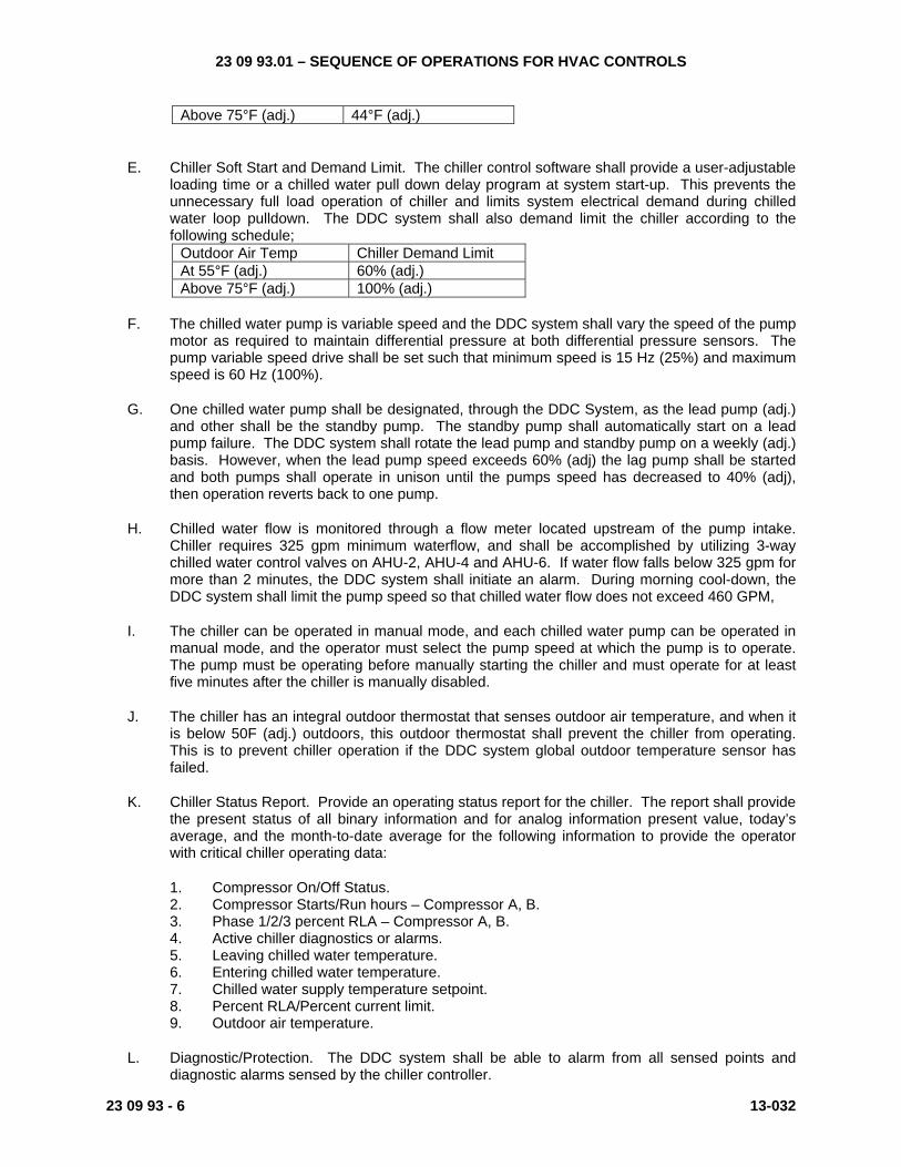
D. The chiller shall be enabled after chilled water pump flow has been proven. When the chiller is enabled, the DDC system shall reset the chiller discharge temperature based on outdoor air temperature according to the following schedule:
Outdoor Air Temp Chilled Water Supply
Temp At 55°F (adj.) 50°F (adj.)
23 09 93.01 – SEQUENCE OF OPERATIONS FOR HVAC CONTROLS
23 09 93 - 6 13-032
Above 75°F (adj.) 44°F (adj.)
E. Chiller Soft Start and Demand Limit. The chiller control software shall provide a user-adjustable loading time or a chilled water pull down delay program at system start-up. This prevents the unnecessary full load operation of chiller and limits system electrical demand during chilled water loop pulldown. The DDC system shall also demand limit the chiller according to the following schedule;
Outdoor Air Temp Chiller Demand Limit At 55°F (adj.) 60% (adj.) Above 75°F (adj.) 100% (adj.)
F. The chilled water pump is variable speed and the DDC system shall vary the speed of the pump motor as required to maintain differential pressure at both differential pressure sensors. The pump variable speed drive shall be set such that minimum speed is 15 Hz (25%) and maximum speed is 60 Hz (100%).
G. One chilled water pump shall be designated, through the DDC System, as the lead pump (adj.) and other shall be the standby pump. The standby pump shall automatically start on a lead pump failure. The DDC system shall rotate the lead pump and standby pump on a weekly (adj.) basis. However, when the lead pump speed exceeds 60% (adj) the lag pump shall be started and both pumps shall operate in unison until the pumps speed has decreased to 40% (adj), then operation reverts back to one pump.
H. Chilled water flow is monitored through a flow meter located upstream of the pump intake. Chiller requires 325 gpm minimum waterflow, and shall be accomplished by utilizing 3-way chilled water control valves on AHU-2, AHU-4 and AHU-6. If water flow falls below 325 gpm for more than 2 minutes, the DDC system shall initiate an alarm. During morning cool-down, the DDC system shall limit the pump speed so that chilled water flow does not exceed 460 GPM,
I. The chiller can be operated in manual mode, and each chilled water pump can be operated in manual mode, and the operator must select the pump speed at which the pump is to operate. The pump must be operating before manually starting the chiller and must operate for at least five minutes after the chiller is manually disabled.
J. The chiller has an integral outdoor thermostat that senses outdoor air temperature, and when it is below 50F (adj.) outdoors, this outdoor thermostat shall prevent the chiller from operating. This is to prevent chiller operation if the DDC system global outdoor temperature sensor has failed.
K. Chiller Status Report. Provide an operating status report for the chiller. The report shall provide the present status of all binary information and for analog information present value, today’s average, and the month-to-date average for the following information to provide the operator with critical chiller operating data:
1. Compressor On/Off Status. 2. Compressor Starts/Run hours – Compressor A, B. 3. Phase 1/2/3 percent RLA – Compressor A, B. 4. Active chiller diagnostics or alarms. 5. Leaving chilled water temperature. 6. Entering chilled water temperature. 7. Chilled water supply temperature setpoint. 8. Percent RLA/Percent current limit. 9. Outdoor air temperature.
L. Diagnostic/Protection. The DDC system shall be able to alarm from all sensed points and diagnostic alarms sensed by the chiller controller.
23 09 93.01 – SEQUENCE OF OPERATIONS FOR HVAC CONTROLS
13-032 23 09 93 - 7
M. All points and diagnostics shall be made available throughout the building control system. The Controls Contractor shall coordinate with the chiller manufacturer to furnish and install the required hardware and software for the information to be relayed through the building control system. The system shall utilize the industry standard BACnet protocol for all information exchange.
N. If the fire alarm system is activated for any reason, such as; smoke detector, pull station, flow switch, etc., the DDC system shall disable the air cooled chiller, and de-energize the chilled water pump, with the time delays described above to remove energy from the chiller exchanger. When the fire alarm system is reset, the DDC system shall automatically restart the chilled water system.
1.6 MECHANICAL ROOM REFRIGERANT MONITORING SYSTEM AND MECHANICAL ROOM EXHAUST FAN
A. A refrigerant monitoring system is located within Mechanical Room. The refrigerant monitoring system consists of a monitoring/control panel, 3 refrigerant sensors with the capability to add one sensor in the future and horn/strobes. The monitoring/control panel shall communicate to the DDC controller the following; Refrigerant monitor trouble, Refrigerant monitor alarm, PPM refrigerant sensed by sensor #1, PPM refrigerant sensed by sensor #2 and PPM refrigerant sensed by sensor #3.
B. The refrigerant monitor shall provide a warning and alarm signal to the DDC controller as follows;
1. Chillers utilizing Refrigerant R134a;
a. Warning if 500 PPM refrigerant is sensed by any refrigerant sensor. b. Alarm if 900 PPM refrigerant is sensed by any refrigerant sensor.
C. The alarm shall be a latching alarm in that all actions that occur after an alarm shall not reset until the alarm is acknowledged and reset at the refrigerant monitoring panel. When an alarm condition occurs, the refrigerant monitor shall directly start exhaust fan EF-XX at full speed, open the associated outdoor air intake, energize horn strobes located within the Room and on the entrance side of the entry door to the Room. The refrigerant monitoring system shall indicate and provide a trouble signal to the DDC controller if a trouble conditions occurs. If the refrigerant monitoring panel losses electrical power all relays shall go to the “normal” position which is starting the exhaust fan, opening the outdoor air intake and activating the horn/strobes.
D. DDC System shall monitor Mechanical Room temperature and start exhaust fan EF-XX at 50% speed when room temperature rises above 85F (adj), and open the associated outdoor air intake. Exhaust fan shall not operate for temperature control when the outdoor air temperature is below 35F (adj).
1.7 AIR HANDLING UNIT AHU-1 – MAIN GYM
A. General Operation
1. The AHU operates as a single zone variable air volume system and consists of; a supply fan with variable frequency drive, exhaust fan with variable frequency drive, variable speed enthalpy energy recovery wheel with outdoor air and exhaust air bypasses, air filters, UVc lights, chilled water cooling coil and pre-heat and reheat heating hot water coils. Note, exhaust fan the variable frequency drive does not have a bypass contactor, that is, this variable frequency drive only contains an inverter section which will control the speed of the motor.
23 09 93.01 – SEQUENCE OF OPERATIONS FOR HVAC CONTROLS
23 09 93 - 8 13-032
2. If the supply fan variable frequency drive is to be operated in manual mode or bypass mode, then sufficient number of VAV box supply air dampers must be manually overridden to allow sufficient supply airflow to prevent activating the high pressure static safety switch.
3. The AHU is scheduled for automatic operation through the DDC system on a time of day basis for occupied and unoccupied modes.
B. Occupied Mode
1. The supply and exhaust fans run continuously, the outdoor air dampers, return air dampers and supply fan modulate as required to maintain minimum outdoor air control point, The unit is controlled as follows
2. The DDC system shall determine the discharge air temperature control point. On a call for cooling, the discharge air temperature shall be maintained at 55F (adj) and the supply fan speed shall vary between 100% (adj) speed and 50% (adj) speed. As the call for cooling diminishes, the supply fan shall slow down to 50% (adj) speed with the supply air temperature maintained at 55F (adj). When the room temperature is between the room cooling temperature setpoint and heating temperature setpoint, the supply fan operate at 50% (adj) speed with the supply air temperature maintained at 55F (adj). When the room temperature falls below the heating temperature setpoint, the supply fan shall operate at 50% (adj) speed and the discharge air temperature shall reset between 55F (adj) and 90F (adj) as required to maintain room temperature heating setpoint. If additional heating is required, the supply air temperature shall be maintained at 90F (adj) and the supply fan speed shall slowly increase (5% speed per minute up to 100% (adj) speed), and then the reverse occurs when less heating is required. See dehumidification cycle below for additional information.
3. The pre-heat coil shall prevent discharge air from this coil falling below 50F (adj) by modulating the heating hot water control serving this coil.
4. Dehumidification cycle – If room relative humidity exceeds 60% (adj) (as sensed by the room sensor) and the outdoor air temperature is above 60F (adj), the system enters dehumidification mode. The AHU cooling coil discharge temperature shall be maintained at 55F (adj.) and the reheat coil shall provide reheat to maintain room temperature. If dehumidification is required while the AHU supply fan is operating between 100% (adj) and 50% (adj) speed, the DDC system shall slowly increase supply fan speed (5% speed per minute up to 100% (adj) speed) and reset discharge air temperature between 55F (adj) and 90F (adj) as required to maintain room temperature cooling temperature setpoint. The system stops dehumidification mode when the room relative humidity falls below 55%.
5. Exhaust fan operation – The DDC system shall operate the exhaust fan variable frequency drive. The exhaust fan is interlocked with the supply fan and exhaust damper end switch and shall not operate until supply fan status is proven and the exhaust damper is fully open. Exhaust air airflow is measured and controlled by the DDC system. The exhaust fan speed shall be based on maintaining a 2000 CFM positive differential between outdoor air airflow and exhaust airflow, and the exhaust fan does not start until outdoor air airflow exceeds 3000 CFM. Exhaust fan motor speed shall not fall below 25% rated speed, and shall not exceed 100% rated speed.
6. Energy Recovery Section Operation
a. The DDC system shall operate the energy recovery section as required to maximize energy recovery, including varying the speed of the energy recovery wheel to control AHU discharge air temperature. The energy recovery section shall
23 09 93.01 – SEQUENCE OF OPERATIONS FOR HVAC CONTROLS
13-032 23 09 93 - 9
maximize energy recovery prior to allowing the heating coil to operate. The energy recovery section shall maximize energy recovery during mechanical cooling by allowing the cooling coil to operate during economizer.
b. Between 65F (adj) and 55F (adj) outdoor air temperature, the energy recovery wheel outdoor air bypass and exhaust air bypass dampers are 100% open and the return air bypass dampers are 100% closed, and, the chilled water coil shall provide cooling as required. Above 65F (adj) outdoor air temperature, the energy recovery wheel outdoor air bypass and exhaust air bypass dampers are 100% closed, the AHU operates on minimum outdoor air, and the energy recovery wheel operates at 100% speed when the return air temperature exceeds the outdoor air temperature by more than 2F DB (adj). Between 55F (adj) and 38F (adj) outdoor air temperature, the energy recovery wheel outdoor air bypass and exhaust air bypass dampers are 100% open, the energy recovery wheel, operates at 100% speed and the return air bypass dampers modulate to maintain unit discharge air temperature and prevent minimum outdoor air from falling below control point, and the heating water coil shall provide additional heat as required. Below 38F (adj) outdoor air temperature, the energy recovery wheel outdoor air bypass and exhaust air bypass dampers are 100% closed, the AHU operates on minimum outdoor air, the energy recovery wheel speed varies as required to maintain discharge air temperature, and the heating coil operates to provide additional heat when the energy recovery wheel cannot provide sufficient heat..
c. Self Cleaning - When the rotor has been still for 30 minutes (adj) the self cleaning function begins by rotating the rotor for 10 seconds (adj) at minimum speed, then stopping the rotor.
d. The energy recovery section shall include a “frost control” mode when the outdoor temperature is below 20F (adj), to prevent the energy recovery wheel from accumulating too much frost. The unit monitors the wheel exhaust side discharge air temperature and prevent it from falling below 15F (adj) by varying the speed of the energy recovery wheel to reduce energy recovery to remove frost from the wheel. when the unit is in "frost control", the graphic display shall indicate that is in "frost control" mode.
e. Rotation monitoring - The Variable Frequency Drive monitors the rotation of the rotor. If the rotor is not rotating while being commanded to rotate, the DDC System shall provide an alarm.
f. During frost control the mixed air temperature sensor shall control the outdoor air and return air dampers to maintain 40F (adj) mixed air temperature, minimum outdoor air control is overridden during “frost control”. If the DDC system detects the energy recovery wheel is not operating when it should be operating when the outdoor air temperature is below 35F (adj), then the mixed air temperature sensor shall control the outdoor air damper and return air damper to maintain 40F (adj) mixed air temperature.
7. Economizer operation – When the outdoor air temperature is below 65F (adj.) economizer operation “free cooling” shall be allowed. The DDC system shall operate the outdoor air and return air dampers, energy recovery section, heating hot water coil control valve and cooling coil control valve in sequence and without overlap to maintain discharge air temperature, that is, if the energy recovery section cannot provide sufficient energy transfer then heating hot water coil control valve shall modulate as required to provide additional heat to maintain discharge air control point, and if the energy recovery wheel is providing too much heat then the exhaust air bypass damper shall modulate and when this damper is fully open and if the energy recovery wheel still provides too much heat then the outside air bypass dampers shall modulate open as required to maintain
23 09 93.01 – SEQUENCE OF OPERATIONS FOR HVAC CONTROLS
23 09 93 - 10 13-032
discharge air temperature. When the outdoor air temperature is above 65F (adj.), economizer is disabled. During economizer operation, outdoor air airflow rate shall not fall below minimum outdoor air airflow control point.
8. Minimum outdoor air airflow. Outdoor air airflow is measured and controlled by the DDC system. Minimum outdoor airflow setpoint adjustment is through the DDC System. If the room CO2 sensor is reading below 1000 ppm (adj) setpoint, then the outdoor air airflow shall be 25% of the value shown on drawing M-701. If the room CO2 sensor is reading above setpoint, then the DDC controller shall modulate the outdoor air airflow up to 100% of the value shown on Drawing M-701, and the DDC controller shall increase supply fan speed as required to maintain outdoor air airflow control point. If the room CO2 sensor continues to read above setpoint for 10 minutes, the DDC system shall issue an alarm. When the outdoor air is below 5F (ajd) the outdoor air shall be 10% of the value shown on drawing M-701.
9. The UVc lights downstream of the cooling coil are energized only when the AHU supply fan is energized by the DDC System. There is a manual “On-Off” switch and access door switch on the AHU, and if the access door is opened, the door switch shall de-energize the UVc lights.
C. Unoccupied Mode
1. When the AHU is “off”, the supply fan is off, the exhaust fan is off, the cooling coil control valve if closed, the heating coil control valve modulates to maintain 70F interior temperature as sensed by the discharge air stat, the outdoor air dampers are closed, the return air dampers are open, and the exhaust air dampers are closed.
2. Unoccupied heating - The DDC system shall monitor the room temperature. When the room temperature falls below 60F (adj.), the AHU shall activate to provide heat to the room. When the AHU is activated, the supply fan shall operate at 100% (adj) speed and the AHU discharge air temperature shall be maintained at 90F (adj.), the exhaust fan remains off, the outdoor air dampers remain closed, the return air dampers remain open and the exhaust dampers remain closed. The AHU shall stop when the room temperature rises to 65F (adj).
3. Unoccupied cooling - The DDC system shall monitor the room temperature. When the room temperature rises above 85F (adj.), the AHU shall start, the supply fan shall operate at 100% speed and discharge 55F supply air, the exhaust fan remains off, the outdoor air dampers remain closed, the return air dampers remain open, the exhaust air dampers remain closed. When the room temperature falls below 80F, the AHU shall stop. Note; Economizer operation shall be utilized if the outdoor air temperature is less than the economizer changeover setpoint, see “Economizer Operation” in Occupied Mode above.
4. Morning warm-up - The DDC system shall monitor the room temperature and outdoor air temperature and automatically start the AHU prior to the occupancy schedule start time based on “optimal start time” to get the room up to occupied setpoint temperature by occupied start time, and during this period of operation the outdoor air dampers remain closed, the return air dampers remain open, the exhaust fan remains off, and exhaust dampers remain closed. During morning warm-up, the AHU supply fan shall operate at 100% speed and discharge 90F (adj.) supply air. The AHU shall enter occupied mode at occupied period start time.
5. Morning cool-down - The DDC system shall monitor the room temperature and outdoor air temperature and automatically start the AHU prior to the occupancy schedule start time based on “optimal start time” to get the room down to occupied setpoint temperature by occupied start time, and during this period of operation the outdoor air dampers remain closed, the return air dampers remain open, the exhaust fan remains off, and the
23 09 93.01 – SEQUENCE OF OPERATIONS FOR HVAC CONTROLS
13-032 23 09 93 - 11
exhaust dampers remain closed. During morning cool-down, the AHU supply fan shall operate at 100% speed and shall discharge 55F (adj.) supply air. The AHU shall enter occupied mode at occupied period start time. Note; Economizer operation shall be utilized if the outside air temperature is less than the economizer changeover setpoint, see “Economizer Operation” in Occupied Mode above.
6. Area relative humidity check - When the outdoor air temperature is above 70F (adj), if the room relative humidity rises above 65% (adj) the AHU supply fan shall operate at 100% speed, the cooling coil shall discharge 55F (adj.) air, the outdoor air dampers remain closed, return air dampers remain open, the exhaust fan remains off, the exhaust air dampers remain closed, and the reheat coil provides reheat as required to maintain unoccupied room temperature setpoint. The AHU stops when the room relative humidity falls below 60%.
D. External Safeties
1. Duct smoke detector, supplied by others, installed in the return air duct shall automatically shut-down the AHU when activated. The AHU shall automatically restart after the fire alarm system has been reset.
2. Activation of any fire alarm pull station or fire sprinkler system water flow switch shall automatically shut-down the AHU when activated. The AHU shall automatically restart after the fire alarm system has been reset.
3. The low temperature cutout stat shall activate if a temperature of less than 38F is sensed at any one foot of the sensing element. When the low temperature cutout stat actives, the AHU immediately shuts down, the pre-heat and re-heat heating coils control valves fully opens, and the DDC system provides an alarm that the low temperature cutout stat has activated. The low temperature cutout stat requires a manual reset.
4. Supply fan and exhaust fan status shall be monitored through the current sensor. If supply fan state changes to “off” when it should be operating, the exhaust fan shall be stopped and the AHU shall go to an “off” state and the DDC system shall generate an alarm. If the exhaust fan state changes to “off” when it should be operating, the DDC system generates an alarm and the AHU continues to operate.
5. The DDC system shall monitor the AHU discharge temperature. If the supply air temperature falls below 50F (adj.) the DDC system shall generate an alarm, and if the supply air temperature falls below 45F (adj.) the DDC system shall stop the AHU, generate an alarm and not allow the AHU to restart until the alarm is acknowledged and the unit is manually restarted. If during occupied mode, the supply air temperature rises above 100F (adj.) the DDC system shall generate an alarm, and if during any mode of operation the supply air temperature rises above 110F (adj.) for 5 minutes the DDC system shall stop the AHU, generate an alarm and not allow the AHU to restart until the alarm is acknowledged and the unit is manually restarted.
1.8 AIR HANDLING UNIT AHU-2 (LOCKERS, TOILETS AND GYM CLASSROOMS)
A. General Operation
1. The AHU operates as a variable air volume system supplying 100% outdoor air and consists of; a supply fan with variable frequency drive, exhaust fan with variable frequency drive, enthalpy energy recovery wheel with outdoor air and exhaust air bypasses, air filters, UVc lights, heating hot water coil, and chilled water cooling coil. Note, these variable frequency drives have a bypass contactor.

23 09 93.01 – SEQUENCE OF OPERATIONS FOR HVAC CONTROLS
23 09 93 - 12 13-032
2. The AHU is scheduled for automatic operation through the DDC system on a time of day basis for occupied and unoccupied modes.
B. Occupied Mode
1. The supply and exhaust fans run continuously. The unit is controlled as follows
2. The DDC system shall determine the discharge air temperature control point. When the outdoor air temperature is above 55F (adj.), the supply air temperature will be maintained at 55F (adj.). When the outdoor air temperature is below 55F (adj.), reset between 55F (adj.) to 62F (adj.) based on the zone with the greatest cooling demand.
3. The DDC system shall determine the supply air duct static pressure control point and shall operate the supply fan variable frequency drive. The DDC system shall monitor the damper position of each terminal unit associated with the AHU and shall reset the supply air duct static pressure control point based on the zone requiring the most pressure, that is, the static pressure control point shall be reset lower until one zone damper is nearly wide open, and the duct static pressure shall be limited to operate between 1.5” WC (adj.) and 3.0” WC (adj.) measured 2/3 downstream of the supply fan discharge. Supply fan motor speed shall not fall below 25% rated speed, and shall not exceed 100% rated speed.
4. Heating coil operation note – The heating coil has a temperature sensor on the downstream side, and its purpose is to prevent the heating coil discharge temperature from falling below 50F (adj.).
5. Energy Recovery Section Operation
a. The DDC system shall operate the energy recovery section as required to maximize energy recovery, including varying the speed of the energy recovery wheel to control AHU discharge air temperature. The energy recovery section shall maximize energy recovery prior to allowing the heating coil to operate. The energy recovery section shall maximize energy recovery during mechanical cooling by allowing the cooling coil to operate during economizer.
b. Between 65F (adj) and 55F (adj) outdoor air temperature, the energy recovery wheel outdoor air bypass and exhaust air bypass dampers are 100%, and, the chilled water coil shall provide cooling as required. Above 65F (adj) outdoor air temperature, the energy recovery wheel outdoor air bypass and exhaust air bypass dampers are 100% closed, and the energy recovery wheel operates at 100% speed when the return air temperature exceeds the outdoor air temperature by more than 2F DB (adj). Below 55F (adj) outdoor air temperature, the energy recovery wheel outdoor air bypass and exhaust air bypass dampers are 100% closed, the energy recovery wheel speed varies as required to maintain discharge air temperature, and the heating coil operates to provide additional heat when the energy recovery wheel cannot provide sufficient heat..
c. Self Cleaning - When the rotor has been still for 30 minutes (adj) the self cleaning function begins by rotating the rotor for 10 seconds (adj) at minimum speed, then stopping the rotor.
d. The energy recovery section shall include a “frost control” mode when the outdoor temperature is below 20F (adj), to prevent the energy recovery wheel from accumulating too much frost. The unit monitors the wheel exhaust side discharge air temperature and prevent it from falling below 15F (adj) by varying the speed of the energy recovery wheel to reduce energy recovery to remove frost from the
23 09 93.01 – SEQUENCE OF OPERATIONS FOR HVAC CONTROLS
13-032 23 09 93 - 13
wheel. when the unit is in "frost control", the graphic display shall indicate that is in "frost control" mode.
e. Rotation monitoring - The Variable Frequency Drive monitors the rotation of the rotor. If the rotor is not rotating while being commanded to rotate, the DDC System shall provide an alarm.
f. During frost control the mixed air temperature sensor shall control the outdoor air and return air dampers to maintain 40F (adj) mixed air temperature, minimum outdoor air control is overridden during “frost control”. If the DDC system detects the energy recovery wheel is not operating when it should be operating when the outdoor air temperature is below 35F (adj), then the mixed air temperature sensor shall control the outdoor air damper and return air damper to maintain 40F (adj) mixed air temperature.
6. The UVc lights downstream of the cooling coil are energized only when the AHU supply fan is energized by the DDC System. There is a manual “On-Off” switch and access door switch on the AHU, and if the access door is opened, the door switch shall de-energize the UVc lights.
C. Unoccupied Mode
1. When the AHU is “off”, the supply fan is off, the exhaust fan is off, the cooling coil control valve if closed, the heating coil control modulates to maintain 70F interior temperature as sensed by the discharge air stat, the outdoor air dampers are closed, the exhaust dampers are closed, the energy recovery wheel bypass dampers are closed.
2. Unoccupied heating – When the space temperature falls below 60F (adj.), the AHU shall activate and the supply fan and exhaust fan shall operate, the unit shall operate on 100% return air, and the unit shall operate as described in “occupied mode” until the space temperature rises above 63F.
3. Unoccupied cooling - When the space temperature rises above 85F (adj.), the AHU shall activate and the supply fan and exhaust fan shall operate, the unit shall operate on 100% return air, and the unit shall operate as described in “occupied mode” until the space temperature falls below 80F.
4. Morning warm-up and morning cool-down – The supply fan and exhaust fan shall operate, the unit shall operate on 100% return air, and the unit shall operate as described in “occupied mode” until the occupied start time. The unit shall utilize optimum start to determine when to energize to bring the space to occupied setpoint by the occupied start time.
5. Area relative humidity check. If relative humidity sensed by the room sensor (see plans for location) rise above 65% and the outdoor air temperature is above 55F, the AHU shall start and supply 55F supply air until the relative humidity falls below 60%. The supply fan and exhaust fan shall operate, the unit shall operate on 100% return air, and the unit shall operate as described in “occupied mode”.
D. External Safeties
1. Duct smoke detector, supplied by others, installed in the exhaust air duct shall automatically shut-down the AHU when activated. The AHU shall automatically restart after the fire alarm system has been reset.
23 09 93.01 – SEQUENCE OF OPERATIONS FOR HVAC CONTROLS
23 09 93 - 14 13-032
2. Activation of any fire alarm pull station or fire sprinkler system water flow switch shall automatically shut-down the AHU when activated. The AHU shall automatically restart after the fire alarm system has been reset.
3. The low temperature cutout stat shall activate if a temperature of less than 38F is sensed at any one foot of the sensing element. When the low temperature cutout stat actives, the AHU immediately shuts down, the heating coil control valve fully opens, and the DDC system provides an alarm that the low temperature cutout stat has activated. The low temperature cutout stat requires a manual reset.
4. Supply fan and exhaust fan status shall be monitored through the current sensor. If supply fan state changes to “off” when it should be operating, the exhaust fan shall be stopped and the AHU shall go to an “off” state and the DDC system shall generate an alarm. If the exhaust fan state changes to “off” when it should be operating the DDC system generate an alarm, the exhaust damper shall close and the AHU continues to operate.
5. The DDC system shall monitor the AHU discharge temperature. If the supply air temperature falls below 50F (adj.) the DDC system shall generate an alarm, and if the supply air temperature falls below 45F (adj.) the DDC system shall stop the AHU, generate an alarm and not allow the AHU to restart until the alarm is acknowledged and the unit is manually restarted. If during occupied mode, the supply air temperature rises above 75F (adj.) the DDC system shall generate an alarm, and if during any mode of operation the supply air temperature rises above 100F (adj.) for 5 minutes the DDC system shall stop the AHU, generate an alarm and not allow the AHU to restart until the alarm is acknowledged and the unit is manually restarted.
E. Other
1. The DDC system shall directly monitor; mixed air temperature, exhaust air temperature, return air temperature, and return air relative humidity.
2. The DDC system shall monitor and display outside air airflow and exhaust air airflow.
3. The DDC system shall directly monitor outside air temperature and relative humidity globally.
4. All safeties shall be wired such that the unit will not start in “auto”, “manual” or “hand”.
1.9 AIR HANDLING UNITS; AHU-3 (CLASSROOMS) AHU-6 (CLASSROOMS) AHU-7 (CLASSROOMS) AHU-8 (CLASSROOMS) AHU-9 (AUDITORIUM)
A. General Operation
1. The AHU operates as a variable air volume system and consists of; a supply fan with variable frequency drive, exhaust fan with variable frequency drive, variable speed enthalpy energy recovery wheel with outdoor air and exhaust air bypasses, air filters, heating hot water coils, chilled water cooling coil, and UVc lights. Note, the exhaust fan variable frequency drive does not have a bypass contactor, that is, this variable frequency drive only contains an inverter section which will control the speed of the motor.
23 09 93.01 – SEQUENCE OF OPERATIONS FOR HVAC CONTROLS
13-032 23 09 93 - 15
2. If the supply fan variable frequency drive is to be operated in manual mode or bypass mode, then sufficient number of VAV box supply air dampers must be manually overridden to allow sufficient supply airflow to prevent activating the high pressure static safety switch.
3. The AHU is scheduled for automatic operation through the DDC system on a time of day basis for occupied and unoccupied modes.
4. Heating coil operation note – The heating coil has a temperature sensor on the downstream side, and its purpose is to prevent the heating coil discharge temperature from falling below 50F (adj.).
B. Occupied Mode
1. The supply and exhaust fans run continuously, the outdoor air dampers and return air dampers modulate as required to maintain minimum outdoor air setpoint. The unit is controlled as follows
2. The DDC system shall determine the discharge air temperature control point. When the outdoor air temperature is above 55F (adj.), the supply air temperature will be maintained at 55F (adj.). When the outdoor air temperature is below 55F (adj.), reset between 55F (adj.) to 62F (adj.) based on the zone with the greatest cooling demand.
3. The DDC system shall determine the supply air duct static pressure control point and shall operate the supply fan variable frequency drive. The DDC system shall monitor the damper position of each terminal unit associated with the AHU and shall reset the supply air duct static pressure control point based on the zone requiring the most pressure, that is, the static pressure control point shall be reset lower until one zone damper is nearly wide open, and the duct static pressure shall be limited to operate between 1.5” WC (adj.) and 3.0” WC (adj.) measured 2/3 downstream of the supply fan discharge. Supply fan motor speed shall not fall below 25% rated speed, and shall not exceed 100% rated speed.
4. Economizer operation – When the outdoor air temperature is below 65F (adj.) economizer operation “free cooling” shall be allowed. The DDC system shall operate the outdoor air and return air dampers, energy recovery section, heating hot water coil control valve and cooling coil control valve in sequence and without overlap to maintain discharge air temperature, that is, if the energy recovery section cannot provide sufficient energy transfer then heating hot water coil control valve shall modulate as required to provide additional heat to maintain discharge air control point, and if the energy recovery wheel is providing too much heat then the exhaust air bypass damper shall modulate and when this damper is fully open and if the energy recovery wheel still provides too much heat then the outside air bypass dampers shall modulate open as required to maintain discharge air temperature. When the outdoor air temperature is above 65F (adj.), economizer is disabled. During economizer operation, outdoor air airflow rate shall not fall below minimum outdoor air airflow control point.
5. Energy Recovery Section Operation
a. The DDC system shall operate the energy recovery section as required to maximize energy recovery, including varying the speed of the energy recovery wheel to control AHU discharge air temperature. The energy recovery section shall maximize energy recovery prior to allowing the heating coil to operate. The energy recovery section shall maximize energy recovery during mechanical cooling by allowing the cooling coil to operate during economizer.
23 09 93.01 – SEQUENCE OF OPERATIONS FOR HVAC CONTROLS
23 09 93 - 16 13-032
b. Between 65F (adj) and 55F (adj) outdoor air temperature, the energy recovery wheel outdoor air bypass and exhaust air bypass dampers are 100% open and the return air bypass dampers are 100% closed, and, the chilled water coil shall provide cooling as required. Above 65F (adj) outdoor air temperature, the energy recovery wheel outdoor air bypass and exhaust air bypass dampers are 100% closed, the AHU operates on minimum outdoor air, and the energy recovery wheel operates at 100% speed when the return air temperature exceeds the outdoor air temperature by more than 2F DB (adj). Between 55F (adj) and 38F (adj) outdoor air temperature, the energy recovery wheel outdoor air bypass and exhaust air bypass dampers are 100% open, the energy recovery wheel, operates at 100% speed and the return air bypass dampers modulate to maintain unit discharge air temperature and prevent minimum outdoor air from falling below control point, and the heating water coil shall provide additional heat as required. Below 38F (adj) outdoor air temperature, the energy recovery wheel outdoor air bypass and exhaust air bypass dampers are 100% closed, the AHU operates on minimum outdoor air, the energy recovery wheel speed varies as required to maintain discharge air temperature, and the heating coil operates to provide additional heat when the energy recovery wheel cannot provide sufficient heat.
c. Self Cleaning - When the rotor has been still for 30 minutes (adj) the self cleaning function begins by rotating the rotor for 10 seconds (adj) at minimum speed, then stopping the rotor.
d. The energy recovery section shall include a “frost control” mode when the outdoor temperature is below 20F (adj), to prevent the energy recovery wheel from accumulating too much frost. The unit monitors the wheel exhaust side discharge air temperature and prevent it from falling below 15F (adj) by varying the speed of the energy recovery wheel to reduce energy recovery to remove frost from the wheel. when the unit is in "frost control", the graphic display shall indicate that is in "frost control" mode.
e. Rotation monitoring - The Variable Frequency Drive monitors the rotation of the rotor. If the rotor is not rotating while being commanded to rotate, the DDC System shall provide an alarm.
f. During frost control the mixed air temperature sensor shall control the outdoor air and return air dampers to maintain 40F (adj) mixed air temperature, minimum outdoor air control is overridden during “frost control”. If the DDC system detects the energy recovery wheel is not operating when it should be operating when the outdoor air temperature is below 35F (adj), then the mixed air temperature sensor shall control the outdoor air damper and return air damper to maintain 40F (adj) mixed air temperature.
6. Exhaust fan operation – The DDC system shall operate the exhaust fan variable frequency drive. The exhaust fan is interlocked with the supply fan and exhaust damper end switch and shall not operate until supply fan status is proven and the exhaust damper is fully open. Exhaust air airflow is measured and controlled by the DDC system. The exhaust fan speed shall be based on maintaining a 1000 CFM positive differential between outdoor air airflow and exhaust airflow, and the exhaust fan does not start until outdoor air airflow exceeds 1500 CFM for AHU units X and X. For AHU-X, the exhaust fan speed shall be based on maintaining a 500 CFM positive differential between outdoor air airflow and exhaust airflow, and the exhaust fan does not start until outdoor air airflow exceeds 1000 CFM. Exhaust fan motor speed shall not fall below 25% rated speed, and shall not exceed 100% rated speed.
7. Minimum outdoor air airflow. Outdoor air airflow is measured and controlled by the DDC system. Minimum outdoor airflow setpoint adjustment is through the DDC System. If all
23 09 93.01 – SEQUENCE OF OPERATIONS FOR HVAC CONTROLS
13-032 23 09 93 - 17
associated space CO2 sensors are reading CO2 below setpoint, then the outdoor air shall be 25% of the value shown on drawing M-701. If any space CO2 sensor is reading above setpoint and the associated VAV box primary air damper has operated at VAV box maximum cooling CFM setpoint for 5 minutes, then the Air Handling Unit controller shall modulate the outdoor air airflow to the design value scheduled on drawing M-701. If that space CO2 sensor continues to read above setpoint for 10 minutes, the Air Handling Unit outdoor air airflow shall be increased an additional 10% of the design value scheduled on drawing M-701, and, if that space CO2 stills reads above setpoint for 10 minutes the DDC system shall issue an alarm and reset the Air Handling Unit outdoor air airflow to the design value scheduled on drawing M-701. When the outdoor air is below 5F (ajd) the outdoor air shall be 10% of the value shown on drawing M-701. See Single Duct Shutoff VAV Box Sequence of Operation for additional information.
8. The UVc lights downstream of the cooling coil are energized only when the AHU supply fan is energized by the DDC System. There is a manual “On-Off” switch and access door switch on the AHU, and if the access door is opened, the door switch shall de-energize the UVc lights.
C. Unoccupied Mode
1. When the AHU is “off”, the supply fan is off, the exhaust fan is off, the cooling coil control valve if closed, the heating coil control modulates to maintain 70F interior temperature as sensed by the discharge air stat, the outdoor air dampers are closed, the return air dampers are open, the return air dampers upstream of the energy recovery wheel are closed, the exhaust dampers are closed, the energy recovery wheel bypass dampers are closed, and, all terminal units associated with the AHU enter unoccupied mode.
2. Unoccupied heating – The DDC system shall monitor each space temperature associated with each terminal unit associated with the AHU. When a space temperature falls below 60F (adj.), fan powered terminal units shall activate their fan and heat the space, and, terminal units without fans shall activate the air handling unit and heat the space, and the terminal unit heating coil shall be utilized to provide heat to the space. When the AHU is activated, the AHU shall maintain 75F (adj.) discharge air temperature and the DDC system shall open the primary air damper in sufficient terminal units to allow the AHU to exceed minimum supply CFM operation.
3. Unoccupied cooling - The DDC system shall monitor each space temperature associated with each terminal unit associated with the AHU. When a space temperature rises above 85F (adj.), the AHU shall start and discharge 55F supply air, the outdoor air dampers remain closed, the return air dampers remain open, the return air dampers upstream of the energy recovery wheel are closed, the exhaust dampers are closed, and the terminal unit serving that space shall go to full cooling mode, and, other terminal units shall go to occupied mode as required to allow the AHU to exceed minimum supply CFM operation. When the critical zone space temperature falls below 80F, the AHU shall stop. Note; Economizer operation shall be utilized if the outside air temperature is less than the economizer changeover setpoint, see “Economizer Operation” in Occupied Mode above.
4. Morning warm-up – The DDC system shall monitor each zone temperature and outdoor air temperature and automatically start the AHU prior to the occupancy schedule start time based on “optimal start time” to get all the spaces up to occupied setpoint temperature by occupied start time, and during this period of operation the outdoor air dampers remain closed, the return air dampers are open, the return air dampers upstream of the energy recovery wheel are closed, the exhaust dampers are closed. During morning warm-up, the AHU shall discharge 75F (adj.) supply air, all terminal units shall operate at maximum cooling CFM setpoint, and all terminal units heating hot water control valve shall modulate as required to maintain room temperature setpoint. This is to allow the AHU to provide additional heat for morning warm-up. When a room
23 09 93.01 – SEQUENCE OF OPERATIONS FOR HVAC CONTROLS
23 09 93 - 18 13-032
temperature rises above the occupied heating setpoint, the FPVAV shall enter occupied mode, and all FPVAV’s shall enter occupied mode at occupied period start time.
5. Morning cool-down - The DDC system shall monitor each zone temperature and outdoor air temperature and automatically start the AHU prior to the occupancy schedule start time based on “optimal start time” to get all the spaces down to occupied setpoint temperature by occupied start time, and during this period of operation the outdoor air dampers remain closed, the return air dampers are open, the return air dampers upstream of the energy recovery wheel are closed, the exhaust dampers are closed. During morning cool-down, the AHU shall discharge 55F (adj.) supply air and each terminal unit shall operate in occupied mode. Note; Economizer operation shall be utilized if the outside air temperature is less than the economizer changeover setpoint, see “Economizer Operation” in Occupied Mode above.
6. Area relative humidity check. If relative humidity sensed by the room sensor (see plans for location) rise above 65% and the outdoor air temperature is above 55F, the AHU shall start and supply 55F supply air until the relative humidity falls below 60%. The AHU outdoor air damper is closed, the exhaust air dampers are closed, and all associated terminal units are at maximum cooling CFM.
D. External Safeties
1. Duct smoke detector, supplied by others, installed in the return air duct shall automatically shut-down the AHU when activated. The AHU shall automatically restart after the fire alarm system has been reset.
2. Activation of any fire alarm pull station or fire sprinkler system water flow switch shall automatically shut-down the AHU when activated. The AHU shall automatically restart after the fire alarm system has been reset.
3. The low temperature cutout stat shall activate if a temperature of less than 38F is sensed at any one foot of the sensing element. When the low temperature cutout stat actives, the AHU immediately shuts down, the heating coil control valve fully opens, and the DDC system provides an alarm that the low temperature cutout stat has activated. The low temperature cutout stat requires a manual reset.
4. A high static pressure cutout switch measures supply air duct static pressure and shall automatically shut-down the AHU when activated and the DDC system shall provide an alarm that the unit has shut-down. The high static cutout switch shall require a manual reset and the AHU shall require a manual restart after the high static pressure cutout switch has reset. The high static cutout switch static pressure setpoint shall be 4.0” WC (adj.).
5. Supply fan and exhaust fan status shall be monitored through the current sensor. If supply fan state changes to “off” when it should be operating, the exhaust fan shall be stopped and the AHU shall go to an “off” state and the DDC system shall generate an alarm. If the exhaust fan state changes to “off” when it should be operating the DDC system generate an alarm, the exhaust damper shall close and the AHU continues to operate.
6. The DDC system shall monitor the AHU discharge temperature. If the supply air temperature falls below 50F (adj.) the DDC system shall generate an alarm, and if the supply air temperature falls below 45F (adj.) the DDC system shall stop the AHU, generate an alarm and not allow the AHU to restart until the alarm is acknowledged and the unit is manually restarted. If during occupied mode, the supply air temperature rises above 75F (adj.) the DDC system shall generate an alarm, and if during any mode of operation the supply air temperature rises above 100F (adj.) for 5 minutes the DDC
23 09 93.01 – SEQUENCE OF OPERATIONS FOR HVAC CONTROLS
13-032 23 09 93 - 19
system shall stop the AHU, generate an alarm and not allow the AHU to restart until the alarm is acknowledged and the unit is manually restarted.
7. Exhaust air volume – The DDC system shall monitor exhaust air airflow rate and not allow the exhaust air airflow rate to exceed the quantity indicated on the drawings in the equipment schedule.
E. Other
1. The DDC system shall directly monitor; mixed air temperature, exhaust air temperature, return air temperature, and return air relative humidity.
2. The DDC system shall directly monitor outside air temperature and relative humidity globally.
3. All safeties shall be wired such that the unit will not start in “auto”, “manual” or “hand”.
4. All points on the DDC system shall be capable of providing a user adjustable alarm and being trended.
1.10 AIR HANDLING UNITS; AHU-4 AND KITCHEN HOOD EXHAUST FAN, STUDENT DINING AND KITCHEN
A. General Operation
1. The AHU operates as a variable air volume system and consists of; a supply fan with variable frequency drive, air filters, UVc lights, pre-heat heating hot water coil, chilled water cooling coil, pre-heat heating coil run-a-round pump, and associated relief air dampers. Note, the variable frequency drive has a bypass contactor.
2. If the supply fan variable frequency drive is to be operated in manual mode or bypass mode, then sufficient number of VAV box supply air dampers must be manually overridden to allow sufficient supply airflow to prevent activating the high pressure static safety switch.
3. The AHU is scheduled for automatic operation through the DDC system on a time of day basis for occupied and unoccupied modes.
4. The heating coil shall have a run-a round pump that operates whenever the outdoor temperature is below 38F or the freeze stat activates. And the heating coil has a temperature sensor on the downstream side, its purpose is to prevent the heating coil discharge temperature from falling below 50F (adj.).
B. Occupied Mode
1. The supply and exhaust fans run continuously, the outdoor air dampers and return air dampers modulate as required to maintain minimum outdoor air setpoint. The unit is controlled as follows
2. The DDC system shall determine the discharge air temperature control point. When the outdoor air temperature is above 55F (adj.), the supply air temperature will be maintained at 55F (adj.). When the outdoor air temperature is below 55F (adj.), reset between 55F (adj.) to 62F (adj.) based on the zone with the greatest cooling demand. The pre-heat coil shall prevent discharge air from this coil falling below 50F (adj) by modulating the heating hot water control serving this coil. The run-a-round pump serving this coil shall operate
23 09 93.01 – SEQUENCE OF OPERATIONS FOR HVAC CONTROLS
23 09 93 - 20 13-032
whenever the unit is operating and the outdoor air temperature is below 40F (adj). See external safeties below for additional information.
3. The DDC system shall determine the supply air duct static pressure control point and shall operate the supply fan variable frequency drive. The DDC system shall monitor the damper position of each terminal unit associated with the AHU and shall reset the supply air duct static pressure control point based on the zone requiring the most pressure, that is, the static pressure control point shall be reset lower until one zone damper is nearly wide open, and the duct static pressure shall be limited to operate between 1.5” WC (adj.) and 3.0” WC (adj.) measured 2/3 downstream of the supply fan discharge. Supply fan motor speed shall not fall below 25% rated speed, and shall not exceed 100% rated speed.
4. Economizer operation – When the outdoor air temperature is below 65F (adj.) economizer operation “free cooling” shall be allowed. The DDC system shall operate the outdoor air and return air dampers, heating hot water coil control valve and cooling coil control valve in sequence and without overlap to maintain discharge air temperature. When the outdoor air temperature is above 65F (adj.), economizer is disabled. During economizer operation, outdoor air airflow rate shall not fall below minimum outdoor air airflow control point.
5. Minimum outdoor air airflow. Outdoor air airflow is measured and controlled by the DDC system. Minimum outdoor airflow setpoint adjustment is through the DDC System. If all associated space CO2 sensors are reading CO2 below setpoint, then the outdoor air shall be 25% of the value shown on drawing M-701. If any space CO2 sensor is reading above setpoint and the associated VAV box primary air damper has operated at VAV box maximum cooling CFM setpoint for 5 minutes, then the Air Handling Unit controller shall modulate the outdoor air airflow to the design value scheduled on drawing M-701. If that space CO2 sensor continues to read above setpoint for 10 minutes, the Air Handling Unit outdoor air airflow shall be increased an additional 10% of the design value scheduled on drawing M-701, and, if that space CO2 stills reads above setpoint for 10 minutes the DDC system shall issue an alarm and reset the Air Handling Unit outdoor air airflow to the design value scheduled on drawing M-701. If the See FPVAV and Single Duct Shutoff VAV Box Sequence of Operation for additional information.
a. The DDC system, through a current sensor, shall monitor Exhaust Fan EF-XX which serves the kitchen exhaust hood. Whenever the Kitchen hood exhaust fan is operating, the minimum outdoor air airflow control point shall be determined by the speed of the Kitchen exhaust fan as this exhaust fan is controlled through a variable frequency drive that provides an analog fan motor speed feedback signal to the Air Handling Unit controller. With exhaust fan EF-XX operating at 100% exhaust fan motor speed, AHU-4 shall provide a minimum of XXXX CFM outdoor air.
b. When a Kitchen Hood fire suppression system is activated, the associated exhaust fan shall energize through the Kitchen Hood Control System, if not already energized, and go to 100% speed, and, the DDC system shall stop Air Handling Unit AHU-4, and initiate an alarm.
Relief Air Damper Operation – The DDC system shall operate the relief air damper motor, and it shall not operate until supply fan status is proven. Room differential pressure with respect to the Corridor is measured and controlled by the DDC system. The relief air damper position shall be based on maintaining the room at 0.05 inch WC (adj) positive with respect to the Corridor.
6. The UVc lights downstream of the cooling coil are energized only when the AHU supply fan is energized by the DDC System. There is a manual “On-Off” switch and access door
23 09 93.01 – SEQUENCE OF OPERATIONS FOR HVAC CONTROLS
13-032 23 09 93 - 21
switch on the AHU, and if the access door is opened, the door switch shall de-energize the UVc lights.
C. Unoccupied Mode
1. When the AHU is “off”, the supply fan is off, the cooling coil control valve if closed, the heating coil control modulates to maintain 70F interior temperature as sensed by the discharge air stat, the outdoor air dampers are closed, and the relief air dampers are closed, and, all terminal units associated with the AHU enter unoccupied mode.
2. Unoccupied heating – The DDC system shall monitor each space temperature associated with each terminal unit associated with the AHU. When a space temperature falls below 60F (adj.), fan powered terminal units shall activate their fan and heat the space, and, terminal units without fans shall activate the air handling unit and heat the space, and the terminal unit heating coil shall be utilized to provide heat to the space. When the AHU is activated, the AHU shall maintain 75F (adj.) discharge air temperature and the DDC system shall open the primary air damper in sufficient terminal units to allow the AHU to exceed minimum supply CFM operation.
3. Unoccupied cooling - The DDC system shall monitor each space temperature associated with each terminal unit associated with the AHU. When a space temperature rises above 85F (adj.), the AHU shall start and discharge 55F supply air, the outdoor air dampers remain closed, the return air dampers are open, the relief air dampers are closed, and the terminal unit serving that space shall go to full cooling mode, and, other terminal units shall go to occupied mode as required to allow the AHU to exceed minimum supply CFM operation. When the critical zone space temperature falls below 80F, the AHU shall stop. Note; Economizer operation shall be utilized if the outside air temperature is less than the economizer changeover setpoint, see “Economizer Operation” in Occupied Mode above.
4. Morning warm-up – The DDC system shall monitor each zone temperature and outdoor air temperature and automatically start the AHU prior to the occupancy schedule start time based on “optimal start time” to get all the spaces up to occupied setpoint temperature by occupied start time, and during this period of operation the outdoor air dampers remain closed, the return air dampers are open, the relief air dampers are closed. During morning warm-up, the AHU shall discharge 75F (adj.) supply air, all terminal units shall operate at maximum cooling CFM setpoint, and all terminal units heating hot water control valve shall modulate as required to maintain room temperature setpoint. This is to allow the AHU to provide additional heat for morning warm-up. When a room temperature rises above the occupied heating setpoint, the FPVAV shall enter occupied mode, and all FPVAV’s shall enter occupied mode at occupied period start time.
5. Morning cool-down - The DDC system shall monitor each zone temperature and outdoor air temperature and automatically start the AHU prior to the occupancy schedule start time based on “optimal start time” to get all the spaces down to occupied setpoint temperature by occupied start time, and during this period of operation the outdoor air dampers remain closed, the return air dampers are open, the relief air dampers are closed. During morning cool-down, the AHU shall discharge 55F (adj.) supply air and each terminal unit shall operate in occupied mode. Note; Economizer operation shall be utilized if the outside air temperature is less than the economizer changeover setpoint, see “Economizer Operation” in Occupied Mode above.
6. Area relative humidity check. If relative humidity sensed by the room sensor (see plans for location) rise above 65% and the outdoor air temperature is above 55F, the AHU shall start and supply 55F supply air until the relative humidity falls below 60%. The AHU outdoor air damper is closed, the exhaust air dampers are closed, and all associated terminal units are at maximum cooling CFM.
23 09 93.01 – SEQUENCE OF OPERATIONS FOR HVAC CONTROLS
23 09 93 - 22 13-032
D. External Safeties
1. Duct smoke detector, supplied by others, installed in the return air duct shall automatically shut-down the AHU when activated. The AHU shall automatically restart after the fire alarm system has been reset.
2. Activation of any fire alarm pull station or fire sprinkler system water flow switch shall automatically shut-down the AHU when activated. The AHU shall automatically restart after the fire alarm system has been reset.
3. The low temperature cutout stat shall activate if a temperature of less than 38F is sensed at any one foot of the sensing element. When the low temperature cutout stat actives, the AHU immediately shuts down, the pre-heat heating coil heating control valve fully opens, the re-heat heating coil control valve fully opens, the pre-heat heating coil run-a-round pump energizes (if not energized), and the DDC system provides an alarm that the low temperature cutout stat has activated. The low temperature cutout stat requires a manual reset.
4. A high static pressure cutout switch measures supply air duct static pressure and shall automatically shut-down the AHU when activated and the DDC system shall provide an alarm that the unit has shut-down. The high static cutout switch shall require a manual reset and the AHU shall require a manual restart after the high static pressure cutout switch has reset. The high static cutout switch static pressure setpoint shall be 4.0” WC (adj.).
5. Supply fan and exhaust fan status shall be monitored through the current sensor. If supply fan state changes to “off” when it should be operating, the exhaust fan shall be stopped and the AHU shall go to an “off” state and the DDC system shall generate an alarm. If the exhaust fan state changes to “off” when it should be operating the DDC system generate an alarm, the exhaust damper shall close and the AHU continues to operate.
6. The DDC system shall monitor the AHU discharge temperature. If the supply air temperature falls below 50F (adj.) the DDC system shall generate an alarm, and if the supply air temperature falls below 45F (adj.) the DDC system shall stop the AHU, generate an alarm and not allow the AHU to restart until the alarm is acknowledged and the unit is manually restarted. If during occupied mode, the supply air temperature rises above 75F (adj.) the DDC system shall generate an alarm, and if during any mode of operation the supply air temperature rises above 100F (adj.) for 5 minutes the DDC system shall stop the AHU, generate an alarm and not allow the AHU to restart until the alarm is acknowledged and the unit is manually restarted.
7. Exhaust air volume – The DDC system shall monitor exhaust air airflow rate and not allow the exhaust air airflow rate to exceed the quantity indicated on the drawings in the equipment schedule.
E. Other
1. The DDC system shall directly monitor; mixed air temperature, exhaust air temperature, return air temperature, and return air relative humidity.
2. The DDC system shall directly monitor outside air temperature and relative humidity globally.
3. All points on the DDC system shall be capable of providing a user adjustable alarm and being trended.
4. All safeties shall be wired such that the unit will not start in “auto”, “manual” or “hand”.
23 09 93.01 – SEQUENCE OF OPERATIONS FOR HVAC CONTROLS
13-032 23 09 93 - 23
1.11 AIR HANDLING UNIT AHU-5 SERVES ADMINISTRATION AREA
A. General Operation
1. The AHU operates as a variable air volume system and consists of; a supply fan with variable frequency drive, return fan with variable frequency drive, relief air section, outdoor air section, air filters, UVc lights, heating hot water coil, and chilled water cooling coil. Note, these variable frequency drives have a bypass contactor.
2. If the supply fan variable frequency drive is to be operated in manual mode or bypass mode, then sufficient number of VAV box supply air dampers must be manually overridden to allow sufficient supply airflow to prevent activating the high pressure static safety switch.
3. The AHU is scheduled for automatic operation through the DDC system on a time of day basis for occupied and unoccupied modes.
4. Heating coil operation note – The heating coil has a temperature sensor on the downstream side, and its purpose is to prevent the heating coil discharge temperature from falling below 50F (adj.).
B. Occupied Mode
1. The supply and return fans run continuously, the outdoor air dampers and relief air dampers modulate as required to maintain minimum outdoor air setpoint, The unit is controlled as follows
2. The DDC system shall determine the discharge air temperature control point. When the outdoor air temperature is above 55F (adj.), the supply air temperature will be maintained at 55F (adj.). When the outdoor air temperature is below 55F (adj.), reset between 55F (adj.) to 62F (adj.) based on the zone with the greatest cooling demand.
3. The DDC system shall determine the supply air duct static pressure control point and shall operate the supply fan variable frequency drive. The DDC system shall monitor the damper position of each terminal unit associated with the AHU and shall reset the supply air duct static pressure control point based on the zone requiring the most pressure, that is, the static pressure control point shall be reset lower until one zone damper is nearly wide open, and the duct static pressure shall be limited to operate between 1.5” WC (adj.) and 3.0” WC (adj.) measured 2/3 downstream of the supply fan discharge. Supply fan motor speed shall not fall below 25% rated speed, and shall not exceed 100% rated speed.
4. Return fan operation – The DDC system shall operate the return fan variable frequency drive. The return fan is interlocked with the supply fan. The return fan speed shall track the supply fan speed. When the AHU is operating in occupied mode, the return fan shall track the supply fan at a rate 10% less (adj.) than the supply fan, that is, when the supply fan is at 100% speed the return fan is at 90% speed. When the AHU is operating in un-occupied mode, the return fan shall track the supply fan, that is, when the supply fan is at 100% speed the return fan is at 100% speed. Return fan motor speed shall not fall below 25% rated speed, and shall not exceed 100% rated speed.
5. Economizer operation – When the outdoor air temperature is below 65 degree F (adj.) economizer operation “free cooling” shall be allowed. The DDC system shall operate the outdoor air and relief air dampers, heating hot water coil control valve and cooling coil control valve in sequence and without overlap to maintain discharge air temperature. The unit shall maximize economizer operation by allowing the cooling coil to operate during economizer. When the outdoor air temperature is above 65F (adj.), economizer is
23 09 93.01 – SEQUENCE OF OPERATIONS FOR HVAC CONTROLS
23 09 93 - 24 13-032
disabled. During economizer operation, outdoor air airflow rate shall not fall below minimum outdoor air airflow setpoint.
6. Minimum outdoor air airflow (as scheduled on drawings). Outdoor air airflow is measured and controlled by the DDC system. Minimum outdoor airflow setpoint adjustment is through the DDC System and is set to maintain the value shown on Drawing M-701. When the outdoor air is below 5F (ajd) the outdoor air shall be 10% of the value shown on drawing M-701.
7. The UVc lights downstream of the cooling coil are energized only when the AHU supply fan is energized by the DDC System. There is a manual “On-Off” switch and access door switch on the AHU, and if the access door is opened, the door switch shall de-energize the UVc lights.
C. Unoccupied Mode
1. When the AHU is “off”, the supply fan is off, the return fan is off, the cooling coil control valve if closed, the heating coil control modulates to maintain 70F interior temperature as sensed by the discharge air temperature sensor, the outdoor air dampers are closed, the exhaust air dampers are closed, and, all terminal units associated with the AHU enter unoccupied mode.
2. Unoccupied heating – The DDC system shall monitor each space temperature associated with each terminal unit associated with the AHU. When a space temperature falls below 60F (adj.), fan powered terminal units shall activate their fan and heat the space, and, terminal units without fans shall activate the air handling unit and heat the space, and the terminal unit heating coil shall be utilized to provide heat to the space. When the AHU is activated, the AHU shall maintain 75F (adj.) discharge air temperature and the DDC system shall open the primary air damper in sufficient terminal units to allow the AHU to exceed minimum supply CFM operation.
3. Unoccupied cooling - The DDC system shall monitor each space temperature associated with each terminal unit associated with the AHU. When a space temperature rises above 85F (adj.), the AHU shall start and discharge 55F supply air, the outdoor air dampers remain closed, the exhaust air dampers remain closed, and the terminal unit serving that space shall go to full cooling mode, and, the DDC system shall open the primary air damper in sufficient terminal units to allow the AHU to exceed minimum supply CFM operation. When the critical zone space temperature falls below 80F, the AHU shall stop. Note; Economizer operation shall be utilized if the outdoor air temperature is less than the economizer changeover setpoint, see “Economizer Operation” in Occupied Mode above.
4. Unoccupied override – There shall be an override pushbutton located in the Admin Area Secretary Room A104 which when depressed during unoccupied periods causes the associated AHU and all terminal units to enter occupied mode for 2 hours to allow the space to be ventilated, cooled or heated.
5. Morning warm-up – The DDC system shall monitor each zone temperature and outdoor air temperature and automatically start the AHU prior to the occupancy schedule start time based on “optimal start time” to get all the spaces up to occupied setpoint temperature by occupied start time, and during this period of operation the outdoor air dampers remain closed and the exhaust dampers are closed. During morning warm-up, the AHU shall discharge 75F (adj.) supply air, all terminal units shall operate at maximum cooling CFM setpoint, and all terminal units heating hot water control valve shall modulate as required to maintain room temperature setpoint. When a room temperature rises above the occupied heating setpoint, the terminal unit shall enter occupied mode, and all terminal units shall enter occupied mode at occupied period start time.
23 09 93.01 – SEQUENCE OF OPERATIONS FOR HVAC CONTROLS
13-032 23 09 93 - 25
6. Morning cool-down - The DDC system shall monitor each zone temperature and outdoor air temperature and automatically start the AHU prior to the occupancy schedule start time based on “optimal start time” to get all the spaces down to occupied setpoint temperature by occupied start time, and during this period of operation the outdoor air dampers remain closed and the exhaust dampers are closed. During morning cool-down, the AHU shall discharge 55F (adj.) supply air and each terminal unit shall operate in occupied mode. Note; Economizer operation shall be utilized if the outside air temperature is less than the economizer changeover setpoint, see “Economizer Operation” in Occupied Mode above.
7. Area relative humidity check. If relative humidity sensed by the room sensor (see plans for location) rise above 65% and the outdoor air temperature is above 55F, the AHU shall start and supply 55F supply air until the relative humidity falls below 60%. The AHU outdoor air damper is closed, the exhaust air dampers are closed, and all associated terminal units are at maximum cooling CFM.
D. External Safeties
1. Duct smoke detector, supplied by others, installed in the return air duct shall automatically shut-down the AHU when activated. The AHU shall automatically restart after the fire alarm system has been reset.
2. Activation of any fire alarm pull station or fire sprinkler system water flow switch shall automatically shut-down the AHU when activated. The AHU shall automatically restart after the fire alarm system has been reset.
3. The low temperature cutout stat shall activate if a temperature of less than 38F is sensed at any one foot of the sensing element. When the low temperature cutout stat actives, the AHU immediately shuts down, the heating coil control valve fully opens, and the DDC system provides an alarm that the low temperature cutout stat has activated. The low temperature cutout stat requires a manual reset.
4. A high static pressure cutout switch measures supply air duct static pressure and shall automatically shut-down the AHU when activated and the DDC system shall provide an alarm that the unit has shut-down. The high static cutout switch shall require a manual reset and the AHU shall require a manual restart after the high static pressure cutout switch has reset. The high static cutout switch static pressure setpoint shall be 4.0” WC (adj.).
5. Supply fan and return fan status shall be monitored through the current sensor. If supply fan state changes to “off” when it should be operating, the return fan shall be stopped and the AHU shall go to an “off” state and the DDC system shall generate an alarm. If the return fan state changes to “off” when it should be operating, the DDC system generates an alarm and the AHU continues to operate.
6. The DDC system shall monitor the AHU discharge temperature. If the supply air temperature falls below 50F (adj.) the DDC system shall generate an alarm, and if the supply air temperature falls below 45F (adj.) the DDC system shall stop the AHU, generate an alarm and not allow the AHU to restart until the alarm is acknowledged and the unit is manually restarted. If during occupied mode, the supply air temperature rises above 75F (adj.) the DDC system shall generate an alarm, and if during any mode of operation the supply air temperature rises above 100F (adj.) for 5 minutes the DDC system shall stop the AHU, generate an alarm and not allow the AHU to restart until the alarm is acknowledged and the unit is manually restarted.
E. Other
23 09 93.01 – SEQUENCE OF OPERATIONS FOR HVAC CONTROLS
23 09 93 - 26 13-032
1. The DDC system shall directly monitor; mixed air temperature, and return air temperature.
2. The DDC system shall directly monitor outside air temperature and relative humidity globally.
3. All points on the DDC system shall be capable of providing a user adjustable alarm and being trended.
4. All safeties shall be wired such that the unit will not start in “auto”, “manual” or “hand”.
1.12 VARIABLE REFRIGERANT FLOW (VRF) SYSTEM SAHU-1; Serves Gym Classroom 1 SAHU-2; Serves Gym Classroom 2 SAHU-3; Serves Gym Classroom 3 VAV-1; Serves SAHU-1 VAV-2; Serves SAHU-2 VAV-3; Serves SAHU-3 BSB-1 - Branch Selector Box HP-1; Heat Pump, Serves above Air Handling Units
A. Controls are furnished with the VRF system and DDC System as shown on the drawings. Each room thermostat controls the associated VRF air handling unit (SAHU) to provide heating or cooling to the space. The VRF master controller communicates with equipment as shown and controls; HP-1 and the refrigerant Branch Selector Box as required per the manufacturer's programming. The DDC System controls the VAV Boxes that supply outdoor air to the rooms.
B. Each indoor unit (SAHU) supply fan shall run continuously during occupied periods to maintain a space temperature setpoint of 75 degrees (adj.) cooling and 70 degrees heating (adj), and shall energize the auxiliary electric heating coil as required if the refrigerant coil cannot provide sufficient heat. The integral cooling coil condensate pan pump shall operate as required to drain cooling coil condensate.
C. The room CO2 sensor shall control the associated VAV box. The VAV terminal unit controller monitors the space CO2 sensor and its primary air airflow station, and modulates the primary air damper between CO2 demand control minimum and maximum CFM settings to maintain space CO2 setpoint. If space CO2 increases above 1000 ppm (adj.), primary air damper shall modulate to maximum CFM position. When space CO2 falls below 1000 ppm (adj), primary air damper modulates to minimum CFM position.
D. Unoccupied heating – The master controller shall monitor each space temperature associated with each terminal unit. When a space temperature falls below 60F (adj.), the system shall operate and heat the space, and the VAV box damper remains closed.
E. Unoccupied cooling – The master controller shall monitor each space temperature associated with each terminal unit. When a space temperature rises above 80F (adj.), the system shall operate and cool the space, and the VAV box damper remains closed.
F. Morning warm-up – The master controller shall monitor each space temperature and outdoor air temperature and automatically start the system prior to the occupancy schedule start time based on “optimal start time” to get all the spaces up to occupied setpoint temperature by occupied start time.
G. Morning cool-down – The master controller shall monitor each space temperature and outdoor air temperature and automatically start the system prior to the occupancy schedule start time
23 09 93.01 – SEQUENCE OF OPERATIONS FOR HVAC CONTROLS
13-032 23 09 93 - 27
based on “optimal start time” to get all the spaces down to occupied setpoint temperature by occupied start time.
H. The DDC system shall monitor the entire system through a BACnet communication protocol. and display temperature within the rooms and provide an alarms as determined by Norton School Maintenance staff.
1.13 VARIABLE REFRIGERANT SYSTEM SAHU-4; Serves Cross-Connect Room SAHU-5; Serves Art Room 1 SAHU-6; Serves Art Room 2 SAHU-7; Serves Art Room 3 ERV-1; Energy Recovery Ventilator, Serves Above Air Handling Units BSB-2 - Branch Selector Box HP-2; Heat Pump, Serves above Air Handling Units
A. All controls are furnished with the VRF system and DDC System as shown on the drawings. Each room thermostat controls the associated VRF air handling unit (SAHU) to provide heating or cooling to the space. The master controller communicates with equipment as shown and controls; HP-2 and the refrigerant Branch Selector Box as required per the manufacturer's programming. The DDC system controls the ERV that exhausts air from the adjacent Toilet Rooms, supplies outdoor air to the Art Rooms, and performs energy recovery between the airstreams.
B. Each indoor unit (SAHU) supply fan shall run continuously during occupied periods to maintain a space temperature setpoint of 75 degrees (adj.) cooling and 70 degrees heating (adj). and shall energize the auxiliary electric heating coil as required if the refrigerant coil cannot provide sufficient heat. The integral cooling coil condensate pan pump shall operate as required to drain cooling coil condensate.
C. The ERV operates during occupied periods and remains off during unoccupied periods. The DDC system monitors each room CO2 sensor. If either CO2 sensor senses above 1000 ppm, the ERV supply and exhaust fan each operate at 100% speed. When both CO2 sensors sense below 1000 ppm the ERV supply and exhaust fan each operate at 60% speed. The DDC system shall provide an alarm if the supply fan or exhaust fan are not operating when commanded to operate. the DDC System shall monitor ERV supply air and exhaust air temperatures.
D. Unoccupied heating – The master controller shall monitor each space temperature associated with each terminal unit. When a space temperature falls below 60F (adj.), the system shall operate and heat the space, and the ERV remains off.
E. Unoccupied cooling – The master controller shall monitor each space temperature associated with each terminal unit. When a space temperature rises above 80F (adj.), the system shall operate and cool the space, and the ERV remains off.
F. Morning warm-up – The master controller shall monitor each space temperature and outdoor air temperature and automatically start the system prior to the occupancy schedule start time based on “optimal start time” to get all the spaces up to occupied setpoint temperature by occupied start time.
G. Morning cool-down – The master controller shall monitor each space temperature and outdoor air temperature and automatically start the system prior to the occupancy schedule start time based on “optimal start time” to get all the spaces down to occupied setpoint temperature by occupied start time.
23 09 93.01 – SEQUENCE OF OPERATIONS FOR HVAC CONTROLS
23 09 93 - 28 13-032
H. The DDC system shall monitor the entire system through a BACnet communication protocol. and display temperature within the rooms, all ERV points, and provide an alarms as determined by Norton School Maintenance staff.
1.14 SINGLE DUCT SHUTOFF VAV BOX
A. Each VAV box has a hot water heating coil or electric heating coil. VAV terminal unit operation is controlled by a controller mounted on the VAV box which communicates to the DDC system.
B. Hot Water Heating coil operation – The hot water coil output is controlled through a modulating 2-way control valve. VAV box heating coil has a discharge air sensor that prevents the supply air temperature from exceeding 90F (adj.) during occupied and unoccupied mode. During morning warm-up mode, supply air temperature shall not exceed 100F (adj.).
C. Electric Heating coil operation - The electric heating coil output is controlled through an SCR that modulates the heating output of the coil. VAV box heating coil has a discharge air sensor that prevents the supply air temperature from exceeding 90F (adj.) during occupied and unoccupied mode. During morning warm-up mode, supply air temperature shall not exceed 100F (adj.).
D. Each space temperature sensor (unless noted otherwise) has an adjustable lever that will allow the temperature setpoint to be increased or decreased by 2F.
E. The space served by the VAV terminal unit is controlled in occupied and unoccupied modes as follows;
1. Occupied mode
The VAV terminal unit is controlled within user defined maximum, minimum cooling and CO2 demand control minimum primary air airflow settings. The VAV terminal unit con-troller monitors the space temperature sensor and primary airflow station, and modulates the primary air damper between CO2 demand control minimum and maximum CFM set-tings to maintain space temperature setpoint. As the space temperature decreases, the VAV terminal unit controller closes the primary air damper until it reaches CO2 demand control minimum CFM (if CO2 demand control has not overridden primary air airflow con-trol point CFM), and upon a further decrease in space temperature the heating hot water coil control valve or electric heater modulates to maintain space temperature setpoint, and if the space temperature continues to fall below setpoint, the system shall first verify the discharge air temperature as heating (above 80°F) and then the primary air damper modulates open up to maximum airflow setting. Space temperature setpoints are 75F during cooling and 70F during heating.
The VAV terminal unit controller monitors the space CO2 sensor (if the space has a CO2 sensor) and primary airflow station, and modulates the primary air damper between min-imum cooling and maximum cooling CFM settings to maintain space CO2 setpoint. If VAV box primary air damper is operating between CO2 demand control minimum CFM and below maximum CFM, and space CO2 increases above 1000 ppm (adj.), primary air damper shall modulate to maximum CFM position, and, if space overcools then hot water coil control valve or electric heater modulates to maintain space temperature setpoint. When space CO2 falls below 1000 ppm, primary air airflow is allowed to fall to CO2 de-mand control minimum CFM if space does not require cooling or heating.
Space CO2 reading shall be transferred to associated Air Handling Unit controller. See Air Handling Unit sequence of operation for additional information.
23 09 93.01 – SEQUENCE OF OPERATIONS FOR HVAC CONTROLS
13-032 23 09 93 - 29
The VAV terminal unit controller also monitors the space relative humidity sensor (if the space has a relative humidity sensor) and primary air airflow station, and modulates the primary air damper between minimum and maximum CFM settings to maintain space rel-ative humidity setpoint. If primary air damper is operating between CO2 demand control minimum CFM and minimum CFM, and space relative humidity increases above 60& (adj.), primary air damper shall modulate to maximum CFM position, and, if space over-cools then hot water coil control valve modulates to maintain space temperature setpoint. When space relative humidity falls below 55% (adj), primary air airflow is allowed to fall to CO2 demand control minimum CFM if space does not require cooling.
2. Unoccupied mode
When the associated Air Handling Unit is in unoccupied mode, the VAV terminal unit is in unoccupied mode. During the unoccupied mode the primary air damper is fully closed. When a space temperature falls below 60F (adj.), the associated Air Handling Unit shall start and the terminal unit shall go to full heating mode and hot water control valve or electric heating coil shall modulate and heat the space. When the critical zone space temperature rises above 65F, the Air Handling Unit shall stop, or, the Air Handling Unit shall operate for a minimum of 30 minutes. When a space temperature rises above 85F (adj.), the associated Air Handling Unit shall start and the terminal unit shall go to full cooling mode. When the critical zone space temperature falls below 80F, the Air Han-dling Unit shall stop, or, the Air Handling Unit shall operate for a minimum of 30 minutes.
Whenever the air handling unit is started, sufficient VAV boxes primary air dampers shall open to allow air handling unit to operate at minimum supply air CFM.
F. See Air Handling Unit sequence of operation for unoccupied heating, unoccupied cooling, morning warm-up and morning cool-down.
1.15 LIGHTING CONTROLS OCCUPANCY SENSOR MONITORED BY DDC SYSTEM
A. Each room that contains a lighting controls occupancy sensor shall have the occupancy sensor monitored by the DDC System. The Gym occupany sensors are monitored from a single point, see Electrical drawings. The DDC System shall be capable of displaying the status of the occupancy sensor as “occupied” or “unoccupied”.
1.16 LIGHTING CONTROLS CONTROLLED BY DDC SYSTEM
A. The DDC System shall provide Form-C relay contacts controlled by the DDC system to operate Corridor lighting controls. These relay contacts are in parallel with the occupancy sensors. The DDC system energize-deenergize these contacts on an occupied unoccupied schedule determined by Norton School. During occupied periods lights remain on. During unoccupied periods the lights are controlled by occupancy sensor. The DDC System shall be capable of displaying the status of each relay as “occupied” or “unoccupied”.
1.17 SPLIT SYSTEM AIR HANDLING UNIT, SERVES CROSS CONNECT ROOM
A. The standalone split system controller controls the system. Room thermostat that controls this system is furnished with the equipment. This system is a backup to the Variable Refrigerant system.
B. The indoor unit (SAHU) supply fan shall run continuously and the refrigerant compressor shall cycle to maintain a space temperature set point of 80 degrees (adj.) year round.
23 09 93.01 – SEQUENCE OF OPERATIONS FOR HVAC CONTROLS
23 09 93 - 30 13-032
C. The DDC system shall monitor and display temperature within the Cross-Connect Room, and provide an alarm if the space temperature exceeds 82F (adj.) or falls below (70F (adj.).
1.18 THROUGH WALL AC UNIT SEQUENCE OF OPERATION, AC-1 THROUGH AC-X, EACH SERVE A TECHNOLGY CLOSET OR ELEVATOR MACHINE ROOM
A. Supply fan shall run continuously and the refrigerant compressor shall cycle to maintain a space temperature set point of 75 degrees (adj.) year round.
1.19 EXHAUST FANS, LOCAL CONTROL EF-XX - See Drawings for quantity and location
A. Line voltage space thermostat cycles the exhaust fan to maintain 85F setpoint. DDC system shall monitor status of each exhaust fan. Exhaust air is directed to ceiling plenum.
1.20 EXHAUST FAN LOCAL CONTROL EF-XX - See Drawings for quantity and location
A. Line voltage space thermostat cycles the exhaust fan to maintain 85F setpoint. DDC system shall monitor status of each exhaust fan. Exhaust air is exhausted to outdoors, and when exhaust is off gravity backdraft damper closes.
1.21 EXHAUST FANS CONTROLLED BY DDC SYSTEM, SEE EXHUAST FAN SCHEDULE ON DRAWING M-XXX - See Drawings for quantity and location
A. DDC system shall energize and de-energize Exhaust fans based on an occupied/unoccupied schedule and as noted herein. DDC system shall monitor status of each exhaust fan.
B. Exhaust fans that serve Toilet Rooms are also controlled by the DDC System in parallel with the occupancy sensor and shall energize exhaust fan based on an occupied-unoccupied schedule. This is to allow the exhaust fan to operate when the toilet room is cleaned in the evening by the Custodians.
C. Exhaust air is exhausted to outdoors, and when exhaust is off gravity backdraft damper closes.
1.22 EXHAUST FANS CONTROLLED BY ROOM OCCUPANCY SENSOR, SEE EXHUAST FAN SCHEDULE ON DRAWING M-XXX - See Drawings for quantity and location
A. Exhaust fan shall energize when occupancy sensor energizes light, and shall de-energize when occupancy sensor turns off light. DDC system shall monitor status of each exhaust fan.
B. Exhaust fans serving Janitor Closets are also controlled by the DDC System in parallel with the occupancy sensor and shall energize exhaust fan based on an occupied-unoccupied schedule.
C. Exhaust air is exhausted to outdoors, and when exhaust is off gravity backdraft damper closes.
1.23 DESTRATIFICTAION FANS - See drawings for quantity and Locations
A. The DDC System shall start and stop destratification fans during occupied periods these fans shall operate when the outdoor air temperature is below 45F (adj). During unoccupied periods these fans remain off. The DDC System does not monitor status of each fan.
23 09 93.01 – SEQUENCE OF OPERATIONS FOR HVAC CONTROLS
13-032 23 09 93 - 31
1.24 EXHAUST FAN EF-23, SERVES MAIN ELECTRICAL ROOM
A. DDC system shall monitor room temperature and cycle exhaust fan as required to maintain 85F (adj) room temperature. When exhaust fan is energized, motorized wall outdoor air damper opens. When exhaust fan is de-energized, motorized wall intake air energize closed and gravity backdraft damper in exhaust fan roof curb close. DDC system shall monitor status of exhaust fan. DDC System shall provide an alarm if room temperature exceeds 90F.
1.25 SCIENCE CLASSROOMS AND ART CLASSROOM – EMERGENCY EXHAUST FANS
A. Exhaust fan is manually energized through a timer switch located on wall, see drawings for location. Timer switch is moved to 60 minute position and exhaust fan is energized for 60 minutes. When exhaust fan is de-energized, gravity backdraft damper located a fan discharge automatically closes to prevent outdoor air from back-drafting into the classroom. DDC system shall monitor status of each exhaust fan.
1.26 ART KILN EXHAUST FAN
A. Exhaust fan is furnished with Art kiln and is manually started and stopped by switch located on fan power cord. When exhaust is off, gravity backdraft damper closes.
1.27 SCIENCE CLASS ROOM FUME HOODS EXHAUST FANS
A. Exhaust fan is furnished with fume hood.
B. Exhaust fan is manually energized and manually de-energized through an “Off-On” switch located on the fume hood. DDC system shall monitor status of each exhaust fan.
C. Fume hood face velocity monitor is wired such that it is de-energized when exhaust fan on-off switch is in the off position.
1.28 CLASSROOM KITCHEN HOODS, EXHAUST FANS
A Exhaust fan is furnished with hood.
B Exhaust fan is manually energized and manually de-energized through an “Off-On” switch located on the hood, and switch is 3-speed.
C Exhaust air is exhausted to outdoors, and when exhaust is off gravity backdraft damper closes.
1.29 DISHWASHER HOOD, EXHAUST FAN
A Exhaust fan is manually energized and manually de-energized through an “Off-On” switch located on the motor starter. DDC system shall monitor status of each exhaust fan.
B Exhaust air is exhausted to outdoors, and when exhaust is off gravity backdraft damper closes.
23 09 93.01 – SEQUENCE OF OPERATIONS FOR HVAC CONTROLS
23 09 93 - 32 13-032
1.30 CABINET UNIT HEATERS CUH-X
A. Cabinet unit heater is controlled by a controller mounted within the unit cabinet which communicates to the DDC system. Cabinet unit heater contains; supply fan, filter, hot water coil, 2-way control valve and a space temperature sensor that senses return air temperature or room temperature. Space served by cabinet unit heater shall be maintained at 70F (adj.). Supply fan operates whenever there is a call for heating, at which time 2-way valve opens full and cabinet unit heater provides heat until space rises above 70F (adj.). Space temperature setpoint is through DDC system.
1.31 MECHANICAL ROOM UNIT HEATERS UH-X
A. Unit mounted thermostat controls 2-way heating coil valve and unit heater supply fan to maintain 60F (adj.) space temperature. When the temperature drops below setpoint, the 2-way heating coil control valve shall fully open and supply fan shall activate.
1.32 KITCHEN FREEZER AND KITCHEN COOLER
A. The DDC system shall monitor the interior temperature of the Kitchen Freezer and Kitchen Cooler and shall provide and alarm based on upper and lower setpoints determined by Norton School System Maintenance staff.
1.33 ELEVATOR SUMP PUMP
A. DDC System monitors each sump pump high level switch and provides an alarm.
1.34 FOUNDATION DRAINAGE SUMP PUMP
A. DDC System monitors each sump pump high level switch and provides an alarm.
1.35 DOMESTIC WATER BOOSTER PUMP
A. The DDC system shall monitor the domestic water booster pump through BACnet communication and display all information provided from the BACnet communication card, and, shall provide an alarm if an alarm condition exists at the domestic water booster pump.
a. Graphic display shall include the information obtained from the booster pump from the BACnet communication. DDC System Contractor shall provide a list of all points to Norton School that can be displayed through the communication link, and then Norton School shall determine which points are to be displayed.
1.36 DOMESTIC HOT WATER SYSTEM
A. The DDC system shall monitor the domestic hot water supply temperature shall provide and alarm based on upper and lower setpoints determined by Norton School System Maintenance staff.
B. The DDC system shall start-stop the domestic hot water recirculation pump, and this pump shall operate continuously 24/7. The DDC System shall monitor the status of the pump and provide an alarm when the pump is not operating and has been commended to operate.
23 09 93.01 – SEQUENCE OF OPERATIONS FOR HVAC CONTROLS
13-032 23 09 93 - 33
C. The DDC system shall monitor each domestic hot water heater through BACnet communication and shall provide an alarm if an alarm condition exists at any domestic hot water heater.
D. The DDC System shall monitor the domestic hot water meter and display; current consumption in gallons per minute (gpm) and cumulative consumption in gallons based on current day, previous day, previous week, previous month and previous year.
E. DDC System contractor shall setup trends for; domestic hot water supply temperature and domestic hot water current consumption. Each point shall be trended every 10 minutes (adj), and, each trend shall be easily displayed by clicking a mouse over the trend description that will be located on the Domestic Hot Water systems graphic page display.
F. Graphic display shall include a display of each domestic water heater with a “hot spot” over the display of the domestic water heater that when hit with the mouse shall go to a text screen showing the information obtained from the electricity meter from the BACnet communication. DDC System Contractor shall provide a list of all points to Norton School that can be displayed through the communication link, and then Norton School shall determine which points are to be displayed.
1.37 DOMESTIC WATER METER
A The DDC System shall monitor the domestic water meter and display; current consumtion in gallons per minute (gpm) and cumulative consumption in gallons based on current day, previous day, previous week, previous month and previous year.
B DDC System contractor shall setup trend for; domestic water current consumption. Point shall be trended every 10 minutes (adj), and, trend shall be easily displayed by clicking a mouse over the trend description that will be located on the Domestic Water Meter graphic page display.
1.38 NATURAL GAS METER AND NATURAL GAS PRESSURE SENSOR
A. The DDC System shall monitor the natural gas meter and display; current consumption in 1000 cubic feet per hour (MCF) and accumulative consumption in thousand cubic feet (MCF) based on current day, previous day, previous week, previous month and previous year.
B. DDC System contractor shall setup trend for; natural gas current consumption. Point shall be trended every 10 minutes (adj), and, trend shall be easily displayed by clicking a mouse over the trend description that will be located on the Natural Gas Meter graphic page display.
C. The DDC System shall monitor the natural gas pressure, and provide a user adjustable alarm point.
1.39 ELECTRICITY METERS WITHIN MAIN SWITCHBOARDS MSB-A, MSB-B and MSB-C and ELECTRICAL SURGE PROTECTOR
A. The Electricity Meters shall communicate to a DDC System controller via Modbus, thus all points monitored by the Electricity Meters can be viewed, trended and alarmed. The Electricity meters are located at each main electrical switchboard, and for each electricity meter the DDC System shall display amperage for each phase, voltage per phase, power factor, power (in kW), power in KVA, and accumulative consumption in KiloWatt Hours based on current day, previous day, previous week, previous month and previous year. If a loss of phase is detected through any electricity meter, all 2-phase (208 volt equipment) and 3-phase HVAC equipment controlled through the DDC system shall automatically shut down and must be manually
23 09 93.01 – SEQUENCE OF OPERATIONS FOR HVAC CONTROLS
23 09 93 - 34 13-032
restarted. DDC System contractor shall setup trends for each electricity meter for; amperage of each phase, voltage, voltage of each phase, power factor, power (in KW), and power (in KVA). Each point shall be trended every 10 minutes (adj), and, each trend shall be easily displayed by clicking a mouse over the trend description that will be located on the Electricity meters graphic page display.
B. Graphic display of each electricity meter shall include a display of each electricity meter with a “hot spot” over the display of the electricity meter that when hit with the mouse shall go to a text screen showing the information obtained from the electricity meter from the Modbus communication. DDC System Contractor shall provide a list of all points to Norton School that can be displayed through the communication link, and then Norton School shall determine which points are to be displayed.
1.40 EMERGENCY GENERATOR TO DDC SYSTEM INTERFACE
A. The DDC system shall monitor the emergency generator, and shall provide an alarm if the emergency generator is activated.
B. Provide all programming and communication conduit and wiring to the BACNet card serving the emergency generator. Refer to electrical drawings for location of this BACnet communications card.
C. Graphic display shall include the information obtained from the emergency generator from the BACnet communication. DDC System Contractor shall provide a list of all points to Norton School that can be displayed through the communication link, and then Norton School shall determine which points are to be displayed.
1.41 FIRE ALARM PANEL TO DDC SYSTEM INTERFACE
A. The DDC system shall monitor the Fire Alarm Panel, and perform functions and be provided with graphic displays as described herein.
B. Provide all programming and communication conduit and wiring to the BACNet card serving the Fire Alarm Panel. Refer to electrical drawings for location of this BACnet communications card.
C. Graphic displays shall include the information obtained from the Fire Alarm Panel from the BACnet communication. DDC System Contractor shall provide a list of all points to Norton School that can be displayed through the communication link, and then Norton School shall determine which points are to be displayed.
1.42 DISPLAY FOR SCHEDULEING “SNOW DAY” OR DELAY START OF SCHOOL
A. The DDC system shall have a graphic display to be utilized to globally place all the HVAC equipment in unoccupied mode for a “Snow Day”, or globally delay the start of the occupied period by a user adjustable time (hours). That is, all occupied start times will be globally delayed by the user adjustable time period. The display shall contain following;
1 Heading – Snow Day and Delay Start of School Day
2 Snow Day – User Input Field “Date and Year”
3 Delay Start of School Day – User Input Fields “Date and Year” and “Delay Time in Hours”
23 09 93.01 – SEQUENCE OF OPERATIONS FOR HVAC CONTROLS
13-032 23 09 93 - 35
1.43 DISPLAY OF SHOWING CURRENT UNACKNOWLEDGED ALARMS AND PAST UNACKNWOLEDGED ALARMS
A. The DDC system shall have a graphic display that shows al current unacknowledged alarms in order received and all past unacknowledged alarms in order received.
PART 2 - PRODUCTS (Not Applicable)
PART 3 - EXECUTION (Not Applicable)
END OF SPECIFICATION 23 09 93
23 09 93.01 – SEQUENCE OF OPERATIONS FOR HVAC CONTROLS
23 09 93 - 36 13-032
THIS PAGE IS INTENTIONALLY BLANK