Embed Size (px)
Citation preview

8/2/2019 2300 or 2400MP Incubator
http://slidepdf.com/reader/full/2300-or-2400mp-incubator 1/23
WATER JACKETED CO2 INCUBATORS
WITH MICROPROCESSOR CONTROL
MODEL: 2310, 2300MP, 2350MP2400MP, 2450MP
INSTALLATION AND OPERATION MANUAL

8/2/2019 2300 or 2400MP Incubator
http://slidepdf.com/reader/full/2300-or-2400mp-incubator 2/23
TABLE OF CONTENTS
SECTION 1.0 RECEIVING AND INSPECTION
SECTION 2.0 GRAPHIC SYMBOLS
SECTION 3.0 INSTALLATION
SECTION 4.0 CONTROL PANEL OVERVIEW
SECTION 5.0 OPERATION
SECTION 6.0 FYRITE CO2 CHECKING
SECTION 7.0 MAINTENANCE
SECTION 8.0 TROUBLESHOOTING
SECTION 9.0 PARTS LIST
SCHEMATICS
REV 08/98 #4861187
These units are CO2 Water Jacketed incubators for professional, industrial or educationaluse where the preparation or testing of materials is done at approximately atmosphericpressure and no flammable volatile, or combustible materials are being heated. Theseunits are not intended for hazardous or household locations or use.
8/2/2019 2300 or 2400MP Incubator
http://slidepdf.com/reader/full/2300-or-2400mp-incubator 3/23
IMPORTANT: READ THIS INSTRUCTION MANUAL IMMEDIATELY.
Your satisfaction and safety require a complete understanding of this unit, including itsproper function and operational characteristics. Be sure operators are given adequate
training before attempting to put the unit in service. NOTE: This equipment must be usedonly for its intended application; any alterations or modifications will void your warranty.
1.0 RECEIVING AND INSPECTION
1.1 The carrier, when accepting shipment, also accepts responsibility for safedelivery and is liable for loss or damage claims. On delivery, you mustinspect for visible exterior damage. Note and describe on the freight bill any
damage found and enter your claim on the form supplied.
1.2 Inspect for concealed loss or damage on the unit itself, both interior andexterior. If any, the carrier will arrange for official inspection to substantiateyour claim. Save the shipping crate until you are sure the unit has beendelivered in good condition.
1.3 If for any reason you must return the unit, contact your customer servicerepresentative for authorization and supply nameplate data. Please see the
manual cover for information on where to contact customer service.
1.4 Make sure all of the equipment indicated on the packing slip is included withthe unit. Carefully check all packaging before discarding. An accessorypackage is included with each unit. The 2310 comes equipped with 3shelves, 4 leveling feet, 1 humidity pan, and supply hose kit. The 2300MPand 2400MP comes equipped with 6 shelves, and 1 humidity pan per chamber, 4 leveling feet and 1 supply hose kit. All units are supplied with apower cord.
8/2/2019 2300 or 2400MP Incubator
http://slidepdf.com/reader/full/2300-or-2400mp-incubator 4/23
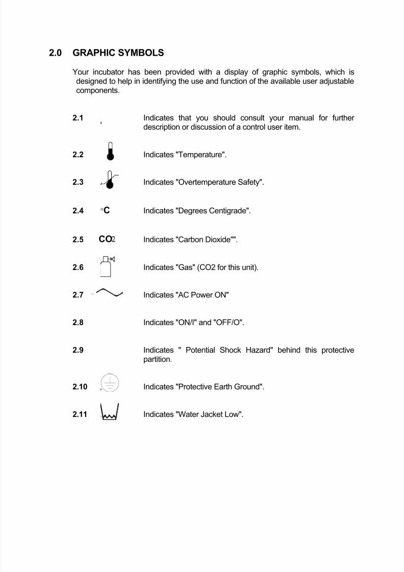
2.0 GRAPHIC SYMBOLS
Your incubator has been provided with a display of graphic symbols, which isdesigned to help in identifying the use and function of the available user adjustablecomponents.
2.1 Indicates that you should consult your manual for further description or discussion of a control user item.
2.2 Indicates "Temperature".
2.3 Indicates "Overtemperature Safety".
2.4 °C Indicates "Degrees Centigrade".
2.5 CO2 Indicates "Carbon Dioxide"".
2.6 Indicates "Gas" (CO2 for this unit).
2.7 Indicates "AC Power ON"
2.8 Indicates "ON/I" and "OFF/O".
2.9 Indicates " Potential Shock Hazard" behind this protectivepartition.
2.10 Indicates "Protective Earth Ground".
2.11 Indicates "Water Jacket Low".
8/2/2019 2300 or 2400MP Incubator
http://slidepdf.com/reader/full/2300-or-2400mp-incubator 5/23
3.0 INSTALLATION
Local city, county, or other ordinances may govern the use of this equipment. If you have any questions about local requirements, please contact the appropriatelocal agency. Installation may be performed by the end user. It is unnecessary for
this unit to be installed by a technician.
Under normal circumstances this unit is intended for use indoors, at roomtemperatures between 5° and 40°C , at no greater than 80% Relative Humidity (at25°C) and with a supply voltage that does not vary by more than 10%. Customer services should be contacted for operating conditions outside of these limits.
CAUTION: Make sure that the incubator is located in its intended positionand level before filling the water jacket.
3.1 Power Source: The power supply must be properly grounded (earthed) andcorrectly sized to match the unit data plate rating. The supply voltage mustmatch the data plate voltage within +\- 10%. These units are intended for 50/60Hz application. If supplied with a detachable cord set, plug the femaleend into the inlet on the unit and the male plug into the supply. Assure thatunits requiring a fuse have a fuse installed. This fuse may be at the inlet or apart of the cord set male plug.
3.2 Location: When selecting a site for the unit, consider conditions which mayaffect performance, such as heat from steam radiators, ovens, autoclaves,etc. Avoid direct sun, fast-moving air currents, heating/cooling ducts, and
high-traffic areas. To ensure air circulation around the unit, allow a minimumof 5cm between the incubator and walls or partitions which might obstructfree airflow.
3.3 Lifting/Handling: These units are heavy and care should be taken to useappropriate lifting devices that are sufficiently rated for these loads. Unitsshould only be lifted from their bottom surfaces. Doors, handles and knobsare not adequate for lifting or transport. All moving parts, such as shelvesand trays should be removed and doors need to be positively locked in theclosed position during transfer to prevent shifting and damage.
3.4 Leveling: The unit must sit level and solidly. Leveling feet are supplied andmust be installed in the four holes in the bottom corners of the unit. With thefeet installed and the unit standing upright, each foot can be raised by turningit in a counterclockwise direction. Adjust the foot at each corner of the unituntil the unit stands level and solid without rocking. If the unit must bemoved, drain all the water from the unit and turn the leveling feet all the wayclockwise to prevent damage while moving.
8/2/2019 2300 or 2400MP Incubator
http://slidepdf.com/reader/full/2300-or-2400mp-incubator 6/23
3.5 Cleaning: The unit chamber should be cleaned and disinfected prior to use.
Remove all of the interior parts, if assembled, and clean thoroughly,including all corners using a suitable disinfectant that is appropriate to your application. Regular periodic cleaning is required. Special care should be
taken when cleaning around sensing heads to prevent damage. DO NOTuse chlorine-based bleaches or abrasive cleaners as this will damage thestainless steel interior.
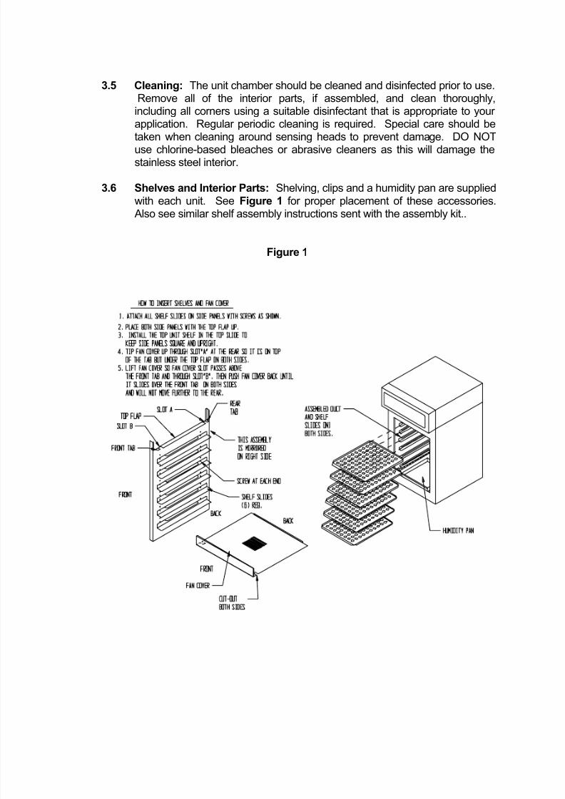
3.6 Shelves and Interior Parts: Shelving, clips and a humidity pan are suppliedwith each unit. See Figure 1 for proper placement of these accessories.Also see similar shelf assembly instructions sent with the assembly kit..
Figure 1
8/2/2019 2300 or 2400MP Incubator
http://slidepdf.com/reader/full/2300-or-2400mp-incubator 7/23
4.0 CONTROL PANEL OVERVIEW (See Figure 2)
Units with a detachable cord have a fused inlet located at the top rear of the controlpanel. This inlet has a recessed male plug, fuse, and a filtering system designed to
protect the circuitry from power surges. This inlet also prevents any internallygenerated interference from feeding back to the power supply system. All controlsare located on the front panel, except the Over Temperature Safety which is locatedat the back.
4.1 Power Switch: The I/O (ON/OFF) switch controls all of the power for theincubator and must be in the I/On position before any systems areoperational. Both Temperature and CO2 displays will illuminate when thepower switch is in the I/ON position.
4.2 Water Low: This pilot lamp will light whenever the internal water jacket floatswitch has been tripped to the closed position. When the water drops lowenough the float switch closes the circuit turning on the indicator light.
4.3 Safety Activated: This pilot lamp will light whenever the Over TemperatureSafety thermostat has activated and taken control of the element. Duringnormal operating conditions this indicator light should never be on.
4.4 Temperature Control: This digital display is marked C° and indicates theactual temperature within the chamber to .1°C. The UP/DOWN buttons areused for imputing the set point, calibrating the display, and muting or unmuting the audible alarm. The HIGH and LOW alarm indicators will lightwhenever there is an alarm condition associated with the temperature withinthe chamber. The MUTE indicator will light whenever the audible alarm hasbeen deactivated.
4.5 Heating: This pilot lamp will light whenever the Temperature Controller isactivating the heating element.
8/2/2019 2300 or 2400MP Incubator
http://slidepdf.com/reader/full/2300-or-2400mp-incubator 8/23
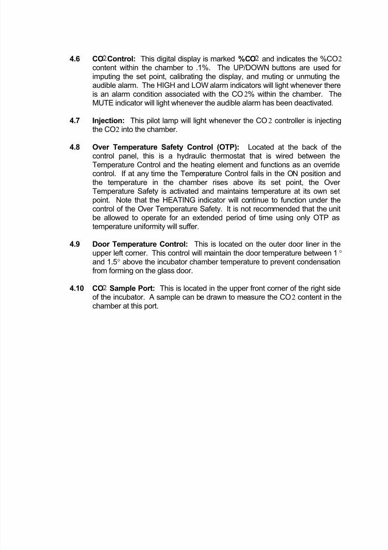
4.6 CO2Control: This digital display is marked %CO2 and indicates the %CO2
content within the chamber to .1%. The UP/DOWN buttons are used for imputing the set point, calibrating the display, and muting or unmuting theaudible alarm. The HIGH and LOW alarm indicators will light whenever there
is an alarm condition associated with the CO2% within the chamber. TheMUTE indicator will light whenever the audible alarm has been deactivated.
4.7 Injection: This pilot lamp will light whenever the CO2 controller is injectingthe CO2 into the chamber.
4.8 Over Temperature Safety Control (OTP): Located at the back of thecontrol panel, this is a hydraulic thermostat that is wired between theTemperature Control and the heating element and functions as an overridecontrol. If at any time the Temperature Control fails in the ON position andthe temperature in the chamber rises above its set point, the Over
Temperature Safety is activated and maintains temperature at its own setpoint. Note that the HEATING indicator will continue to function under thecontrol of the Over Temperature Safety. It is not recommended that the unitbe allowed to operate for an extended period of time using only OTP astemperature uniformity will suffer.
4.9 Door Temperature Control: This is located on the outer door liner in theupper left corner. This control will maintain the door temperature between 1° and 1.5° above the incubator chamber temperature to prevent condensationfrom forming on the glass door.
4.10 CO2 Sample Port: This is located in the upper front corner of the right sideof the incubator. A sample can be drawn to measure the CO2 content in thechamber at this port.
8/2/2019 2300 or 2400MP Incubator
http://slidepdf.com/reader/full/2300-or-2400mp-incubator 9/23
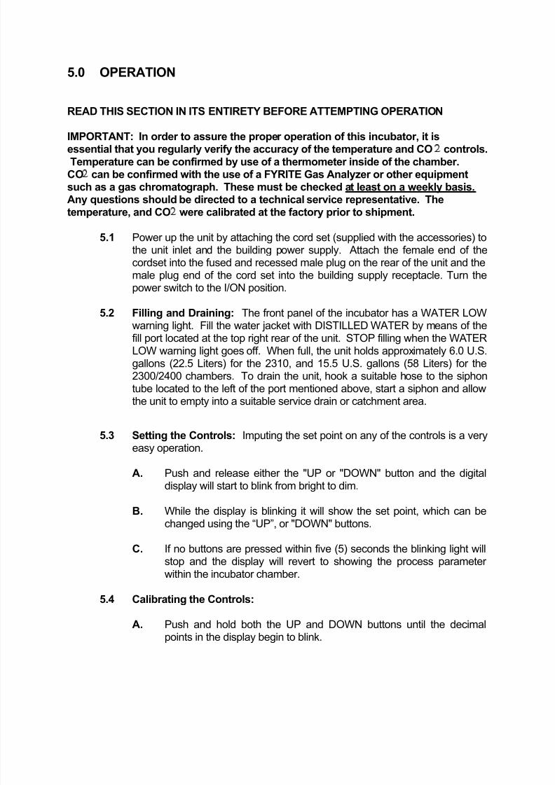
5.0 OPERATION
READ THIS SECTION IN ITS ENTIRETY BEFORE ATTEMPTING OPERATION
IMPORTANT: In order to assure the proper operation of this incubator, it isessential that you regularly verify the accuracy of the temperature and CO2 controls.Temperature can be confirmed by use of a thermometer inside of the chamber.CO2 can be confirmed with the use of a FYRITE Gas Analyzer or other equipmentsuch as a gas chromatograph. These must be checked at least on a weekly basis.Any questions should be directed to a technical service representative. Thetemperature, and CO2 were calibrated at the factory prior to shipment.
5.1 Power up the unit by attaching the cord set (supplied with the accessories) tothe unit inlet and the building power supply. Attach the female end of thecordset into the fused and recessed male plug on the rear of the unit and the
male plug end of the cord set into the building supply receptacle. Turn thepower switch to the I/ON position.
5.2 Filling and Draining: The front panel of the incubator has a WATER LOWwarning light. Fill the water jacket with DISTILLED WATER by means of thefill port located at the top right rear of the unit. STOP filling when the WATERLOW warning light goes off. When full, the unit holds approximately 6.0 U.S.gallons (22.5 Liters) for the 2310, and 15.5 U.S. gallons (58 Liters) for the2300/2400 chambers. To drain the unit, hook a suitable hose to the siphontube located to the left of the port mentioned above, start a siphon and allowthe unit to empty into a suitable service drain or catchment area.
5.3 Setting the Controls: Imputing the set point on any of the controls is a veryeasy operation.
A. Push and release either the "UP or "DOWN" button and the digitaldisplay will start to blink from bright to dim.
B. While the display is blinking it will show the set point, which can bechanged using the “UP”, or "DOWN" buttons.
C. If no buttons are pressed within five (5) seconds the blinking light willstop and the display will revert to showing the process parameter within the incubator chamber.
5.4 Calibrating the Controls:
A. Push and hold both the UP and DOWN buttons until the decimalpoints in the display begin to blink.
8/2/2019 2300 or 2400MP Incubator
http://slidepdf.com/reader/full/2300-or-2400mp-incubator 10/23
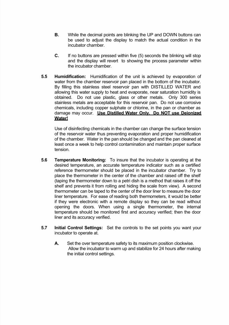
B. While the decimal points are blinking the UP and DOWN buttons can
be used to adjust the display to match the actual condition in theincubator chamber.
C. If no buttons are pressed within five (5) seconds the blinking will stopand the display will revert to showing the process parameter withinthe incubator chamber.
5.5 Humidification: Humidification of the unit is achieved by evaporation of water from the chamber reservoir pan placed in the bottom of the incubator.By filling this stainless steel reservoir pan with DISTILLED WATER andallowing this water supply to heat and evaporate, near saturation humidity isobtained. Do not use plastic, glass or other metals. Only 300 seriesstainless metals are acceptable for this reservoir pan. Do not use corrosivechemicals, including copper sulphate or chlorine, in the pan or chamber as
damage may occur. Use Distilled Water Only. Do NOT use DeionizedWater!
Use of disinfecting chemicals in the chamber can change the surface tensionof the reservoir water thus preventing evaporation and proper humidificationof the chamber. Water in the pan should be changed and the pan cleaned atleast once a week to help control contamination and maintain proper surfacetension.
5.6 Temperature Monitoring: To insure that the incubator is operating at thedesired temperature, an accurate temperature indicator such as a certified
reference thermometer should be placed in the incubator chamber. Try toplace the thermometer in the center of the chamber and raised off the shelf (taping the thermometer down to a petri dish is a method that raises it off theshelf and prevents it from rolling and hiding the scale from view). A secondthermometer can be taped to the center of the door liner to measure the door liner temperature. For ease of reading both thermometers, it would be better if they were electronic with a remote display so they can be read withoutopening the doors. When using a single thermometer, the internaltemperature should be monitored first and accuracy verified; then the door liner and its accuracy verified.
5.7 Initial Control Settings: Set the controls to the set points you want your incubator to operate at.
A. Set the over temperature safety to its maximum position clockwise.Allow the incubator to warm up and stabilize for 24 hours after makingthe initial control settings.
8/2/2019 2300 or 2400MP Incubator
http://slidepdf.com/reader/full/2300-or-2400mp-incubator 11/23
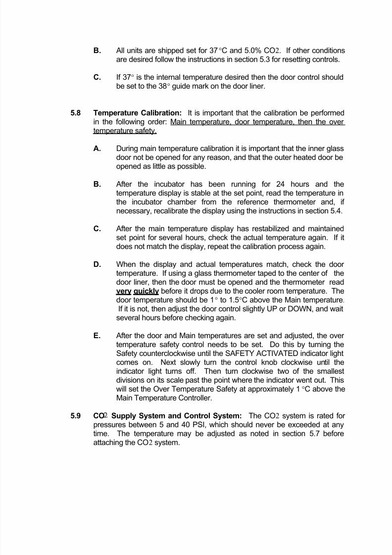
B. All units are shipped set for 37°C and 5.0% CO2. If other conditionsare desired follow the instructions in section 5.3 for resetting controls.
C. If 37° is the internal temperature desired then the door control shouldbe set to the 38° guide mark on the door liner.
5.8 Temperature Calibration: It is important that the calibration be performedin the following order: Main temperature, door temperature, then the over temperature safety.
A. During main temperature calibration it is important that the inner glassdoor not be opened for any reason, and that the outer heated door beopened as little as possible.
B. After the incubator has been running for 24 hours and the
temperature display is stable at the set point, read the temperature inthe incubator chamber from the reference thermometer and, if necessary, recalibrate the display using the instructions in section 5.4.
C. After the main temperature display has restabilized and maintainedset point for several hours, check the actual temperature again. If itdoes not match the display, repeat the calibration process again.
D. When the display and actual temperatures match, check the door temperature. If using a glass thermometer taped to the center of thedoor liner, then the door must be opened and the thermometer read
very quickly before it drops due to the cooler room temperature. Thedoor temperature should be 1° to 1.5°C above the Main temperature.If it is not, then adjust the door control slightly UP or DOWN, and waitseveral hours before checking again.
E. After the door and Main temperatures are set and adjusted, the over temperature safety control needs to be set. Do this by turning theSafety counterclockwise until the SAFETY ACTIVATED indicator lightcomes on. Next slowly turn the control knob clockwise until theindicator light turns off. Then turn clockwise two of the smallestdivisions on its scale past the point where the indicator went out. This
will set the Over Temperature Safety at approximately 1°C above theMain Temperature Controller.
5.9 CO2 Supply System and Control System: The CO2 system is rated for pressures between 5 and 40 PSI, which should never be exceeded at anytime. The temperature may be adjusted as noted in section 5.7 beforeattaching the CO2 system.
8/2/2019 2300 or 2400MP Incubator
http://slidepdf.com/reader/full/2300-or-2400mp-incubator 12/23
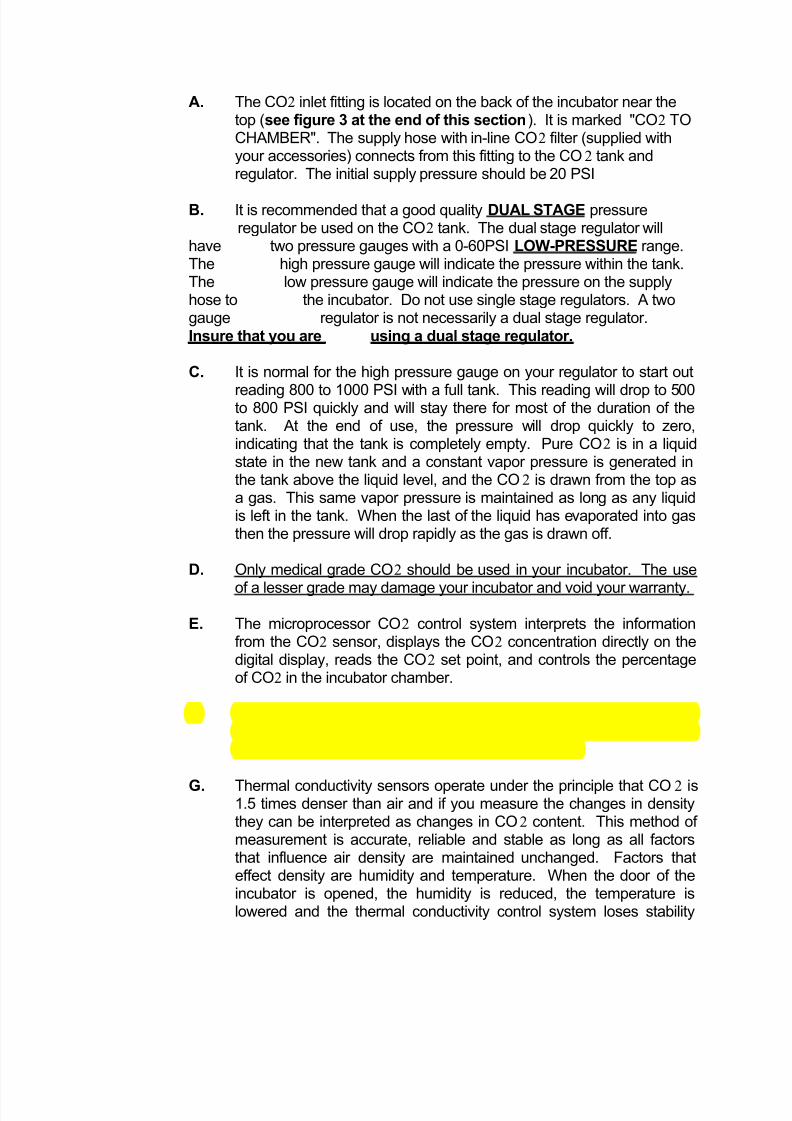
A. The CO2 inlet fitting is located on the back of the incubator near thetop (see figure 3 at the end of this section). It is marked "CO2 TOCHAMBER". The supply hose with in-line CO2 filter (supplied withyour accessories) connects from this fitting to the CO2 tank andregulator. The initial supply pressure should be 20 PSI
B. It is recommended that a good quality DUAL STAGE pressureregulator be used on the CO2 tank. The dual stage regulator will
have two pressure gauges with a 0-60PSI LOW-PRESSURE range.The high pressure gauge will indicate the pressure within the tank.The low pressure gauge will indicate the pressure on the supplyhose to the incubator. Do not use single stage regulators. A twogauge regulator is not necessarily a dual stage regulator.Insure that you are using a dual stage regulator.
C. It is normal for the high pressure gauge on your regulator to start out
reading 800 to 1000 PSI with a full tank. This reading will drop to 500to 800 PSI quickly and will stay there for most of the duration of thetank. At the end of use, the pressure will drop quickly to zero,indicating that the tank is completely empty. Pure CO2 is in a liquidstate in the new tank and a constant vapor pressure is generated inthe tank above the liquid level, and the CO2 is drawn from the top asa gas. This same vapor pressure is maintained as long as any liquidis left in the tank. When the last of the liquid has evaporated into gasthen the pressure will drop rapidly as the gas is drawn off.
D. Only medical grade CO2 should be used in your incubator. The use
of a lesser grade may damage your incubator and void your warranty.
E. The microprocessor CO2 control system interprets the informationfrom the CO2 sensor, displays the CO2 concentration directly on thedigital display, reads the CO2 set point, and controls the percentageof CO2 in the incubator chamber.
F. There are two types of CO2 sensors available, thermal conductivity(TC) and infrared (IR). The 2310 and 2300 units operate with TCsensors, and the 2400 units operate with IR sensors.
G. Thermal conductivity sensors operate under the principle that CO2 is1.5 times denser than air and if you measure the changes in densitythey can be interpreted as changes in CO2 content. This method of measurement is accurate, reliable and stable as long as all factorsthat influence air density are maintained unchanged. Factors thateffect density are humidity and temperature. When the door of theincubator is opened, the humidity is reduced, the temperature islowered and the thermal conductivity control system loses stability
8/2/2019 2300 or 2400MP Incubator
http://slidepdf.com/reader/full/2300-or-2400mp-incubator 13/23
until the conditions in the incubator have recovered to originalconditions.
H. Infrared sensors operate under the principle that a certain frequency
of infrared light is absorbed by CO2. The more CO2 is present themore light is absorbed. Advantages to this system are that it is onlysensitive to CO2, so its accuracy is consistent no matter what theconditions are in the incubator.
I. Both types of CO2 sensors are factory calibrated and under normalcircumstances need no calibration in the field, how ever, it isrecommended that the accuracy of your CO2 control system bemonitored by measuring the actual CO2 concentration on a weeklybasis with a FYRITE or other measuring device. This should be donewhen the chamber has not been disturbed for an extended period of
time i.e. after the weekend or first thing on Monday morning. See5.10.
5.10 Setting the CO2 Control: Set the CO2 control to the desired set point usingthe procedure described in section 5.3. Attach the supply hose to theincubator and turn on the CO2 supply.
5.11 Adjusting CO2 Display: After the incubator has had several hours tostabilize at CO2 set point, measure the actual CO2% with a Fyrite. If there isany difference between the Fyrite and the display, use the procedure
described in section 5.4 for making the display match the Fyrite. SeeSection 6.0 for Fyrite use.
NOTE: When using the Fyrite, insure that gas is not being injected while thereading is being taken. Change the CO2 set point to 0.0 prior to taking thesample, and then change the set point back to the desired value after the useof the Fyrite.
5.12 Alarm Conditions: The temperature control and the CO2 control are bothequipped with visual and audible alarms.
A. Temperature Alarms: The temperature control has alarm indicatorsfor high and low conditions that are activated whenever the actualtemperature is 1C° above or 1C° below the set point.
B. CO2 Alarms: The CO2 controller has alarm indicators for high andlow alarm conditions that are activated whenever the actual CO2% is1% above or below the set point.
8/2/2019 2300 or 2400MP Incubator
http://slidepdf.com/reader/full/2300-or-2400mp-incubator 14/23
C. Audible Alarms: Both controls are equipped with audible alarms that
are activated when either of the HIGH or LOW indicators areactivated. The audible alarms can be muted for a single alarmoccurrence by pressing and holding down either the UP or DOWN
button for several seconds until the alarm mutes. There is a built indelay of 15 minutes on the occurrence of a LOW alarm. Thisprevents the audible alarm from activating every time the door isopened and the temperature drops.
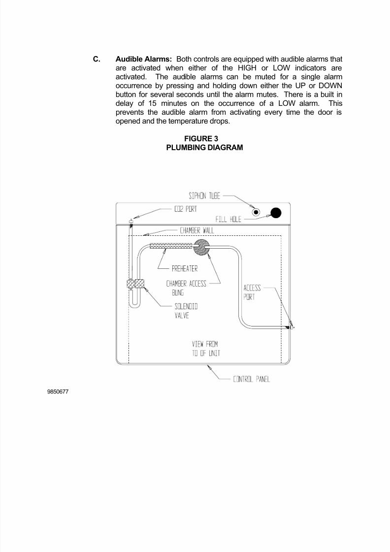
FIGURE 3PLUMBING DIAGRAM
9850677

8/2/2019 2300 or 2400MP Incubator
http://slidepdf.com/reader/full/2300-or-2400mp-incubator 15/23
6.0 FYRITE CO2 CHECKING:
A Bacharach FYRITE CO2 Gas Analyzer is recommended to measure CO2 concentrations in the incubator chamber. This test instrument is not supplied withthe incubator but is readily available from your dealer. Follow the instructions
provided with the Fyrite instrument carefully to insure correct and accurate readings.
1. Press button on top of Fyrite canister to release CO2 concentration. Tipcanister to the side to ensure all fluid is released from the top of canister.
2. Loosen screw on slide scale and align top of fluid with zero on the scale.Tighten screw.
3. Connect hose and aspirator bulb to unit being tested. The sample port for connection is located in the upper front corner of the right side of the incubator.
4. Place the hose sampling cap directly over the plunger valve on top of canister and depress firmly.
5. With button depressed, squeeze bulb 27 times. On the last squeeze, and withbulb still deflated, release hose from button.
6. Turn Fyrite canister upside down 3 times, each time allowing all fluid to flowto the opposite end of the canister.
7. Tip canister to the 45 degree position to ensure all fluid has been releasedfrom top of canister.
8. Read CO2 concentration in %.
NOTE: Your Fyrite indicator will come with a complete set of detailed instructionswhich should be followed carefully. The fluid used inside this Fyrite instrument ispoisonous and corrosive and must not be taken internally. In event of a spill or accidental body contact with the Fyrite fluid, follow instructions on the refill bottlecarefully.
8/2/2019 2300 or 2400MP Incubator
http://slidepdf.com/reader/full/2300-or-2400mp-incubator 16/23
7.0 MAINTENANCE
NOTE: Prior to any maintenance or service on this unit, disconnect theservice cord from the power supply.
7.1 Cleaning: Cleaning and decontamination are recommended on a regular basis. To prepare the incubator for cleaning remove all parts such as theshelf standards and humidity pan. All stainless steel parts are autoclavable.
A. First clean the chamber with soap and water, rinse and let dry. Todecontaminate use a disinfectant that is appropriate and effective to your application. Do not use chlorine-based bleach or abrasives as this willdamage the chamber interior.
B. Clean the humidity pan and replenish it with distilled water on a weeklybasis.
7.2 Check CO2 supply periodically; don't let it run out. (Automatic tank switchesare available from your dealer.)
7.3 CO2 supply lines and connections can be checked for leaks with a liquidsoap solution. Apply a liquid soap solution to all areas of the CO2 supply lineand then look for bubbles which will indicate a leak.
7.4 Keep the CO2 flow system free of impurities. Erratic CO2 control is usuallytraceable to the CO2 pressure regulator on the tank, impurities in the tank, or impurities in the solenoid valve. Replace the CO2 in-line filter annually or
when the filter has become noticeably dirty on the upstream side.
7.5 There is no maintenance necessary for controls. If controls fail to operate asspecified, review Section 8.0, Troubleshooting before calling for service.
7.6 Storage: If the incubator is to be turned off for any length of time, dry thechamber and humidity pan thoroughly and leave at room temperature.Failure to do this may cause the interior to become contaminated. Noadjustment to controls should be required when restarting the unit.
8/2/2019 2300 or 2400MP Incubator
http://slidepdf.com/reader/full/2300-or-2400mp-incubator 17/23
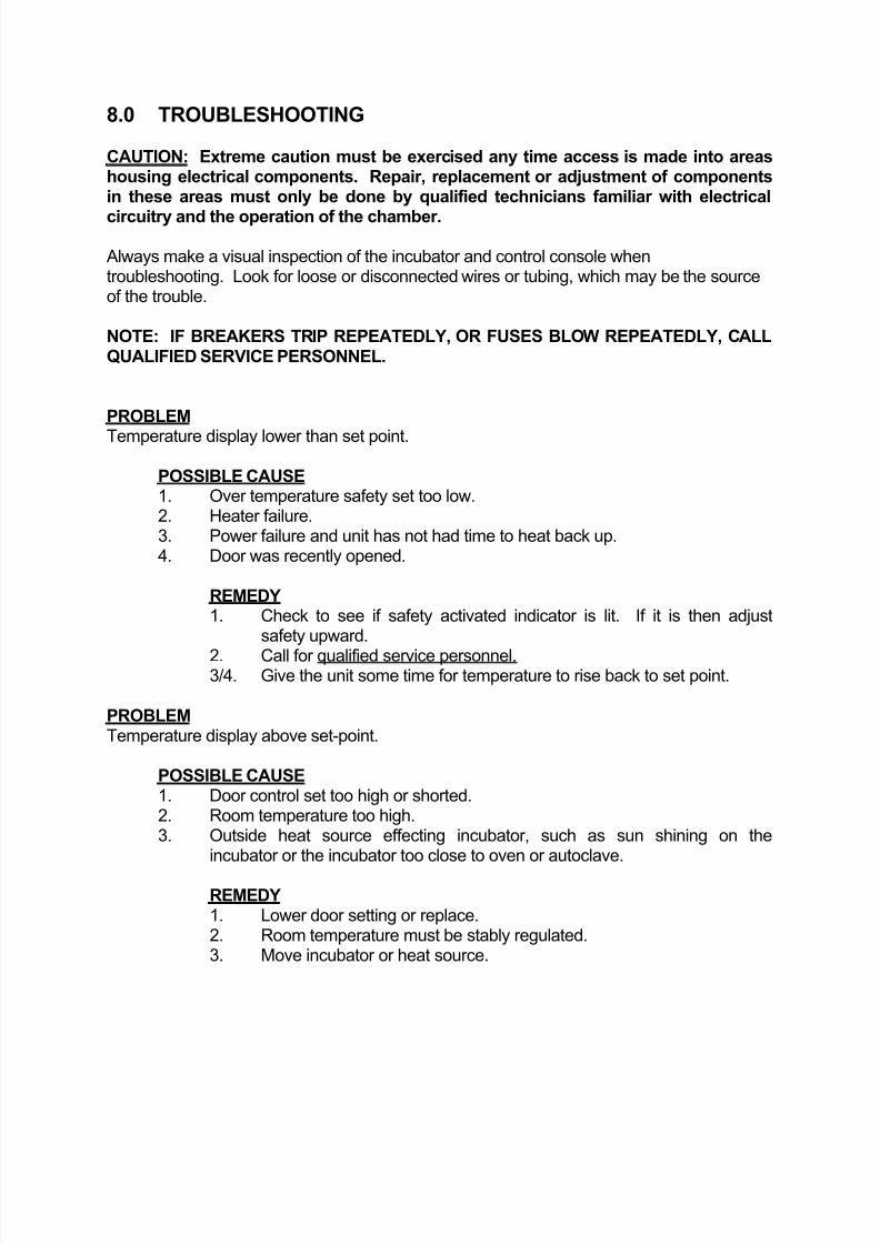
8.0 TROUBLESHOOTING
CAUTION: Extreme caution must be exercised any time access is made into areashousing electrical components. Repair, replacement or adjustment of componentsin these areas must only be done by qualified technicians familiar with electrical
circuitry and the operation of the chamber.
Always make a visual inspection of the incubator and control console whentroubleshooting. Look for loose or disconnected wires or tubing, which may be the sourceof the trouble.
NOTE: IF BREAKERS TRIP REPEATEDLY, OR FUSES BLOW REPEATEDLY, CALLQUALIFIED SERVICE PERSONNEL.
PROBLEM
Temperature display lower than set point.
POSSIBLE CAUSE 1. Over temperature safety set too low.2. Heater failure.3. Power failure and unit has not had time to heat back up.4. Door was recently opened.
REMEDY 1. Check to see if safety activated indicator is lit. If it is then adjust
safety upward.
2. Call for qualified service personnel.3/4. Give the unit some time for temperature to rise back to set point.
PROBLEM Temperature display above set-point.
POSSIBLE CAUSE 1. Door control set too high or shorted.2. Room temperature too high.3. Outside heat source effecting incubator, such as sun shining on the
incubator or the incubator too close to oven or autoclave.
REMEDY 1. Lower door setting or replace.2. Room temperature must be stably regulated.3. Move incubator or heat source.
8/2/2019 2300 or 2400MP Incubator
http://slidepdf.com/reader/full/2300-or-2400mp-incubator 18/23
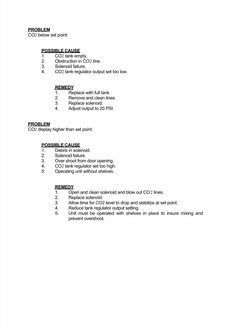
PROBLEM CO2 below set point.
POSSIBLE CAUSE
1. CO2 tank empty.2. Obstruction in CO2 line.3. Solenoid failure.4. CO2 tank regulator output set too low.
REMEDY 1. Replace with full tank.2. Remove and clean lines.3. Replace solenoid.4. Adjust output to 20 PSI.
PROBLEM CO2 display higher than set point.
POSSIBLE CAUSE 1. Debris in solenoid.2. Solenoid failure.3. Over shoot from door opening.4. CO2 tank regulator set too high.
5. Operating unit without shelves.
REMEDY 1. Open and clean solenoid and blow out CO2 lines.2. Replace solenoid.3. Allow time for CO2 level to drop and stabilize at set point.4. Reduce tank regulator output setting.5. Unit must be operated with shelves in place to insure mixing and
prevent overshoot.
8/2/2019 2300 or 2400MP Incubator
http://slidepdf.com/reader/full/2300-or-2400mp-incubator 19/23
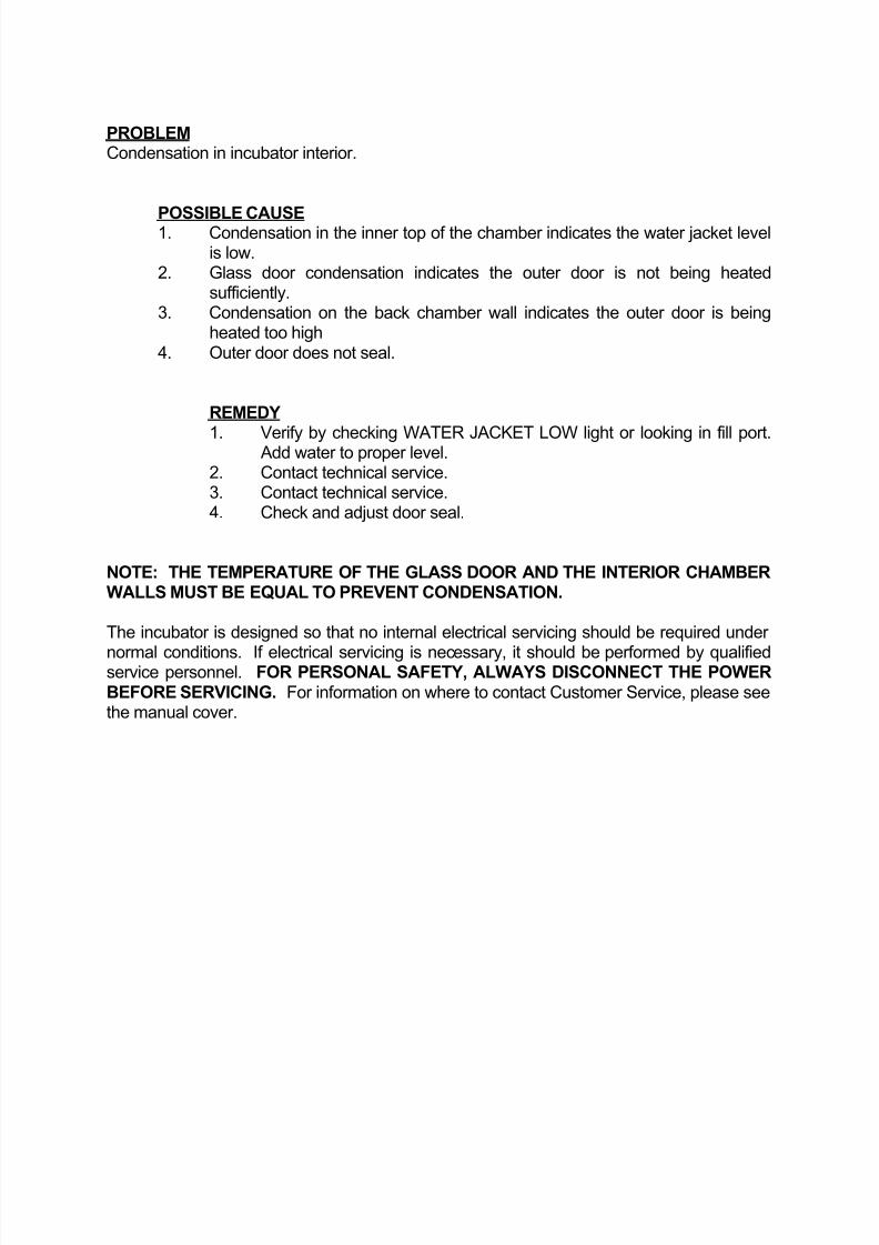
PROBLEM Condensation in incubator interior.
POSSIBLE CAUSE 1. Condensation in the inner top of the chamber indicates the water jacket levelis low.
2. Glass door condensation indicates the outer door is not being heatedsufficiently.
3. Condensation on the back chamber wall indicates the outer door is beingheated too high
4. Outer door does not seal.
REMEDY
1. Verify by checking WATER JACKET LOW light or looking in fill port.Add water to proper level.
2. Contact technical service.3. Contact technical service.4. Check and adjust door seal.
NOTE: THE TEMPERATURE OF THE GLASS DOOR AND THE INTERIOR CHAMBERWALLS MUST BE EQUAL TO PREVENT CONDENSATION.
The incubator is designed so that no internal electrical servicing should be required under
normal conditions. If electrical servicing is necessary, it should be performed by qualifiedservice personnel. FOR PERSONAL SAFETY, ALWAYS DISCONNECT THE POWERBEFORE SERVICING. For information on where to contact Customer Service, please seethe manual cover.
8/2/2019 2300 or 2400MP Incubator
http://slidepdf.com/reader/full/2300-or-2400mp-incubator 20/23
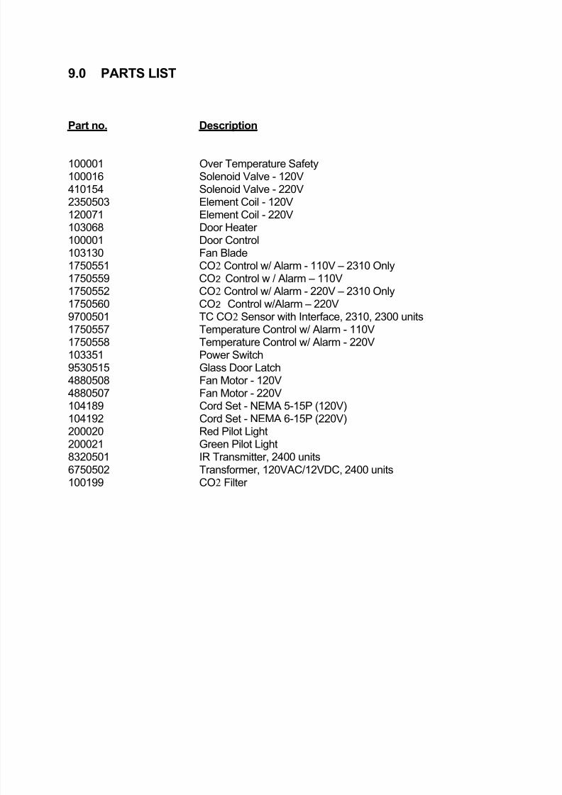
9.0 PARTS LIST
Part no. Description
100001 Over Temperature Safety100016 Solenoid Valve - 120V410154 Solenoid Valve - 220V2350503 Element Coil - 120V120071 Element Coil - 220V103068 Door Heater 100001 Door Control103130 Fan Blade1750551 CO2 Control w/ Alarm - 110V – 2310 Only
1750559 CO2 Control w / Alarm – 110V1750552 CO2 Control w/ Alarm - 220V – 2310 Only1750560 CO2 Control w/Alarm – 220V9700501 TC CO2 Sensor with Interface, 2310, 2300 units1750557 Temperature Control w/ Alarm - 110V1750558 Temperature Control w/ Alarm - 220V103351 Power Switch9530515 Glass Door Latch4880508 Fan Motor - 120V4880507 Fan Motor - 220V104189 Cord Set - NEMA 5-15P (120V)
104192 Cord Set - NEMA 6-15P (220V)200020 Red Pilot Light200021 Green Pilot Light8320501 IR Transmitter, 2400 units6750502 Transformer, 120VAC/12VDC, 2400 units100199 CO2 Filter
8/2/2019 2300 or 2400MP Incubator
http://slidepdf.com/reader/full/2300-or-2400mp-incubator 21/23
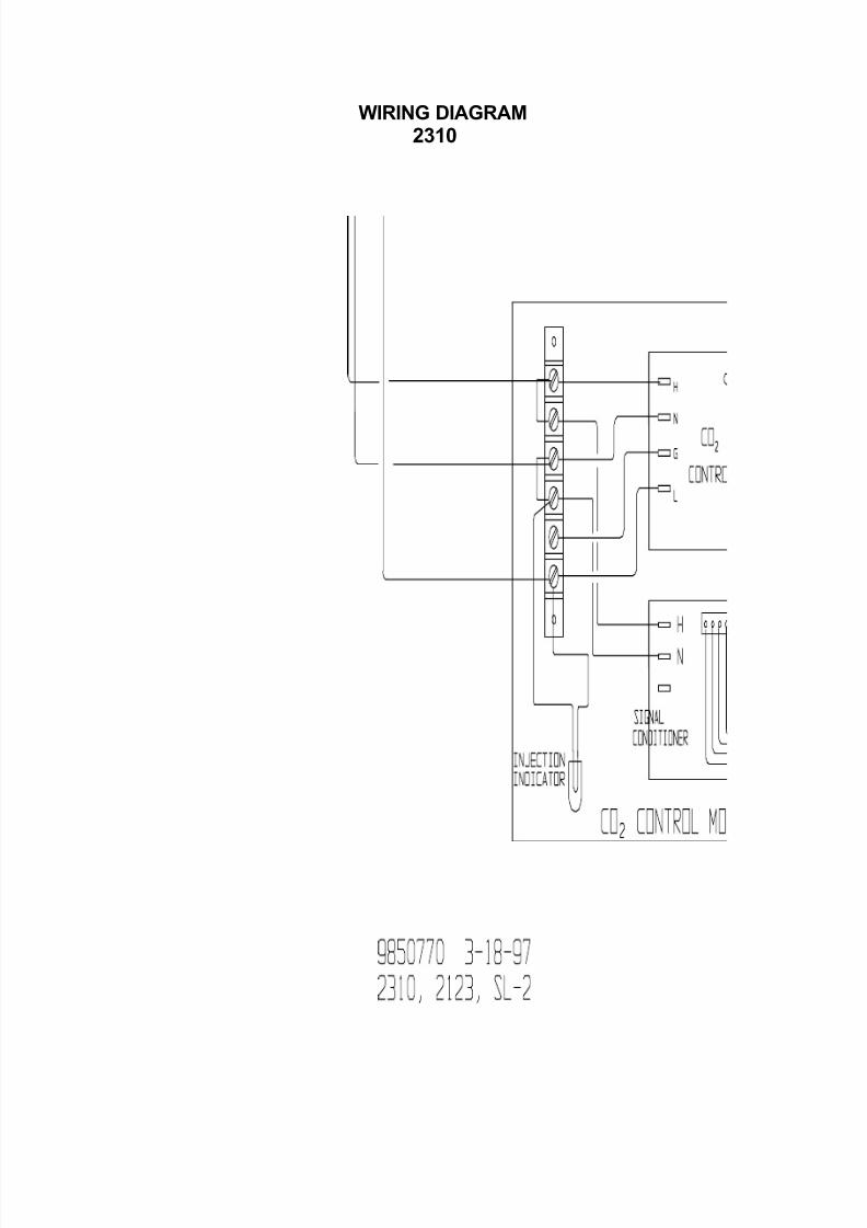
WIRING DIAGRAM 2310
8/2/2019 2300 or 2400MP Incubator
http://slidepdf.com/reader/full/2300-or-2400mp-incubator 22/23
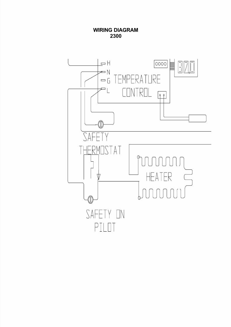
WIRING DIAGRAM2300
8/2/2019 2300 or 2400MP Incubator
http://slidepdf.com/reader/full/2300-or-2400mp-incubator 23/23
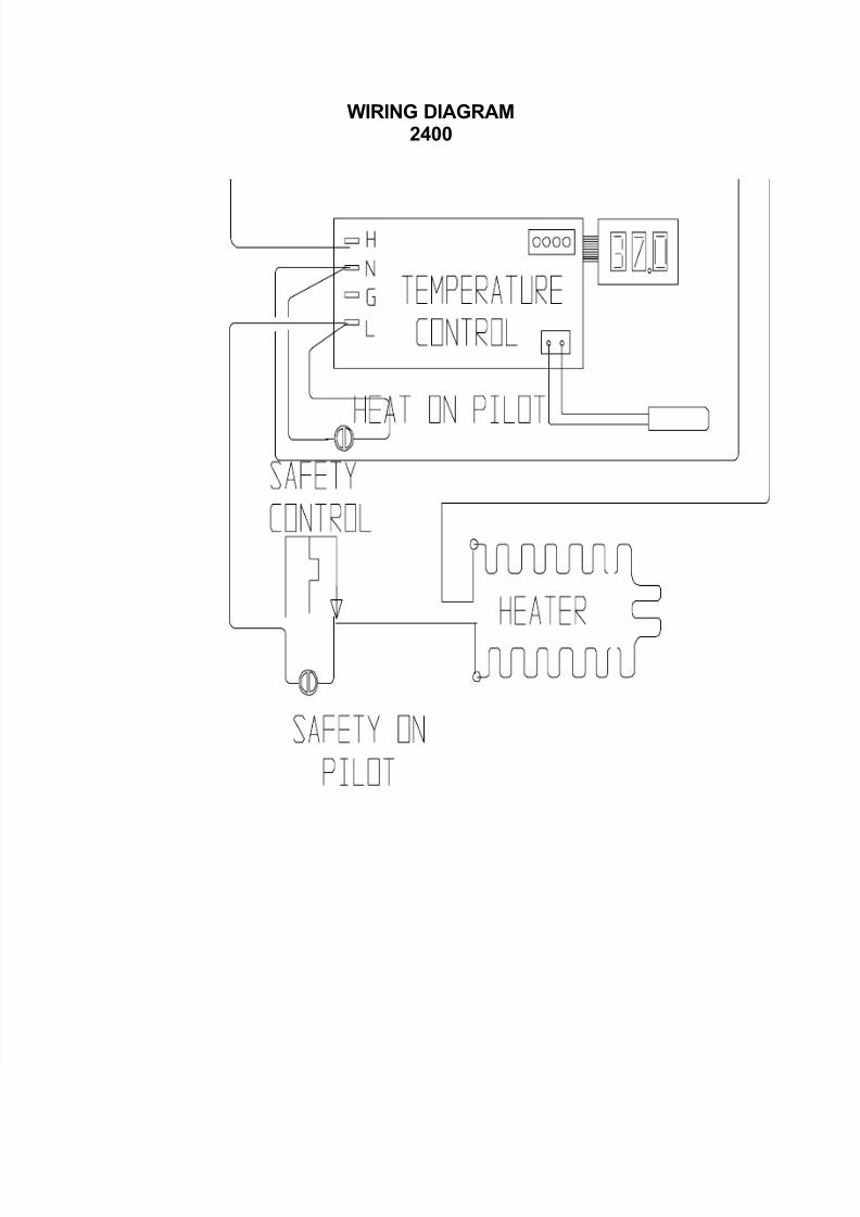
WIRING DIAGRAM2400


![[XLS] - Mar15/District Reasi new proforma... · Web view2035 2300 2036 2300 2037 2300 2038 2300 2039 2300 2040 2300 2041 2300 2042 2300 2043 2300 2044 2300 2045 2300 2046 2300 2047](https://img.pdfslide.us/doc/110x75/5aa68dbc7f8b9a517d8ea409/xls-mar15district-reasi-new-proformaweb-view2035-2300-2036-2300-2037-2300.jpg)