Embed Size (px)
Citation preview

Features and Benefits• High pressure construction eliminates
undesirable regulators and relief valves for supply pressures.
• Hydraulic dampening provides smooth“open-close” operation to preventdetrimental valve slamming.
• Ductile iron housing provides longproduct life with durable, cost effectiveoperation.
• Output shaft made of high strength alloysteel or 17-4PH stainless transmitstorque without fatigue.
• Sintered bronze bushings or Teflon®
composite bearings on output shafteliminate sideloading of valve stem tomaximize stem packing performance.
• Chrome-plated steel piston rod providesstrength and corrosion resistance forenduring high-cycle applications.
• Sintered bronze piston rod bushingsprovide low-friction support and precisealignment of the piston rod to increaseefficiency, reduce maintenance andextend actuator life.
• Heat-treated stainless steel thrust pin and rollers transfer piston force to 17-4PH stainless steel or ductile ironyoke by rolling to reduce friction, forlonger life and more efficient torquetransmission.
• Teflon® guide bands ensure low-frictionpiston guidance during operation toprotect cylinder walls from potentialscoring and extend seal performance with a continuous cylinder wiping action.
• Bi-directional travel stops provideaccurate valve rotation adjustment.
• ISO 5211 mounting promotes easier valve adaption by utilizing internationallyrecognized mounting patterns.
• NAMUR drive slot on output shaftenables accessory-driven componentsto maintain a compact, low profile assembly.
• Tectyl-coated springs can be disarmedwithout special tools to safely and easilydisassemble the actuator in the field,reducing down time and providing a “man-safe” spring.
• Easily removable housing coverprovides effortless access for internalinspection.
General ApplicationsDesigned specifically for automating quarter-turn pipeline valves, providingcontrol for any quarter-turn ball, plug or butterfly valve application.
Technical DataSupply pressure: Up to 2,250 psig
(see torque chart, MORMC-0333)
Supply medium: Any pneumatic orhydraulic fluidcompatible withmaterials ofconstruction.
Temperature ratingStandard: -20°F to 210°FOptional: -65°F to 300°F Angular rotation: 90 degrees ±8 degrees
Morin Series HP Actuator
Copyright © 2011 Tyco Flow Control. All rights reserved. MORMC-0072-US-1103
Flow ControlMorin is either a trademark or registered trademark of Tyco International Services AG or its affiliates in theUnited States and/or other countries. All other brand names, product names, or trademarks belong to theirrespective holders.
2,250 psig Operating Pressure RatingDirect Gas/Hydraulic ActuatorsDuctile Iron/Stainless Steel Quarter-turnDouble Acting and Spring Return Models

Morin Series HP Actuator
Copyright © 2011 Tyco Flow Control. All rights reserved. MORMC-00722
Principles of ConstructionUsing high quality materials of construction and modern rugged designconcepts Morin becomes the standard for low cost valve actuation whileproviding high quality performance.
The actuator housings are all machined from ductile iron castings. Thisproduces a rugged, low cost product through reduced machining timeand by eliminating wasteful excess material. Housings are then epoxyelectro-coated inside and out for corrosion resistance
Any components that rotate or slide during operation, such as the highstrength output shaft, chrome-plated piston rod, stainless steel thrust pinor the ductile iron piston, are all supported by replaceable frictionreducing bearings.
Bi-directional Travel StopsAdjustable stops on each end capprovide the flexibility of accurate valverotation positioning at the end of the“open” and “close” stroke. Both stops arelocated on the cylinder centerline, theoptimal position to maximize traveladjustment and eliminate any detrimentalside loading on the travel stops.Adjustable from 82° to 98°.
Morin Scotch Yoke The heart of any scotch yoke actuator is the yoke. Morin uses either 17-4PH orductile iron for this critical area as standard.
The yoke is the mechanism used to convert linear force to torque. The yoke iscritical to actuator performance. It must be rugged, yet precisely machined togive long life at high efficiency. Morin understands this and ensures that all ouryoke designs meet this test.
Morin has a Rugged Heart
Spring Designed for SafetyAll spring return models incorporate a“man safe” spring design that allowsthe actuator to be safely assembledand disassembled in the field withoutthe need for special tools. The integraltie rods are bored and tapped toprovide a means of loading andunloading the spring in a safe andconvenient manner.
Scotch Yoke Torque Characteristics (symmetrical shown)
Single Acting Spring Return Double Acting Air to Air
AirBreak
SpringBreak
SpringEnd
AirEnd
Break Torque
ActualTorque
PublishedTorque
Stroke
AirStroke
RunningTorque
SpringStroke
125
100
75
50
25
0°45°
90°
125
100
75
50
25
0°45°
90°
Torque
Stroke
Torque

Morin Series HP Actuator
Copyright © 2011 Tyco Flow Control. All rights reserved. MORMC-00723
Piston Rod BearingsSintered bronze
Shaft BearingsSintered bronze orTeflon® composite
Hydraulic Heavy WalledCylinderSteel HeadsSteel Cylinder Xylan™ CoatedDuctile Iron Piston powder coated
Scotch Yoke 17-4PH or A335 Ductile Iron
Model HP15 is standard with 17-4PH shaft.
Housing A395 Ductile Iron
Ductile Iron powder coated
Spring CylinderDuctile Iron has powder coated
Steel Cylinder Xylan™ CoatedDuctile Iron Piston powder coated
Superior materials of construction offer long life, and mean less downtime
Note: See Morin Series HP IOM for a complete bill of materials.
Morin Understands Actuator DesignMorin understands that the most efficient design for one torque range is not the most efficient for another. Morin uses the standard scotchyoke design for lower torque ranges and a side bar design for the higher torque ranges. This gives a rugged design with economic cost.
Standard Design, Scotch Yoke Side Bar Design, Scotch Yoke
Morin Series HP Actuator
Copyright © 2011 Tyco Flow Control. All rights reserved. MORMC-00724
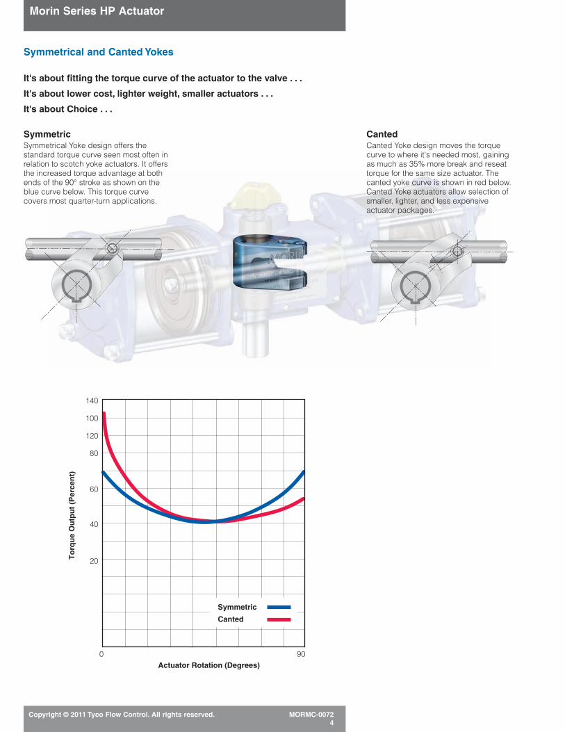
Symmetrical and Canted Yokes
It's about fitting the torque curve of the actuator to the valve . . .
It's about lower cost, lighter weight, smaller actuators . . .
It's about Choice . . .
Actuator Rotation (Degrees)900
To
rqu
e O
utp
ut
(Per
cen
t)
140
100
120
80
60
40
20
Symmetric
Canted
SymmetricSymmetrical Yoke design offers thestandard torque curve seen most often inrelation to scotch yoke actuators. It offersthe increased torque advantage at bothends of the 90° stroke as shown on theblue curve below. This torque curvecovers most quarter-turn applications.
CantedCanted Yoke design moves the torquecurve to where it's needed most, gainingas much as 35% more break and reseattorque for the same size actuator. Thecanted yoke curve is shown in red below.Canted Yoke actuators allow selection ofsmaller, lighter, and less expensiveactuator packages.

Morin Series HP Actuator
Copyright © 2011 Tyco Flow Control. All rights reserved. MORMC-00725
Mechanical Data
Actuator Cylinder Volume Symmetric CantedModel Bore Stroke Cubic In Weight MOP* MAP** MOP* MAP**
Double Acting (inch) (inch) 90° Stroke (lbs) (psi) (psi) (psi) (psi)
HP15-2-1DA 2.13 3 11 30 1900 2250
HP15-2-2DA 2.13 3 19 43 1500 2250HP15-3-1DA 3.25 3 25 48 700 1500
HP15-3-2DA 3.25 3 47 61 600 1500HP25-3-1DA 3.25 5 41 155 2000 2250
HP25-3-2DA 3.25 5 73 186 1600 2250HP25-4-1DA 4.25 5 71 160 1100 2250
HP25-4-2DA 4.25 5 133 196 900 2250HP30-4-1DA 4.25 6 85 365 2250 2250
HP30-4-2DA 4.25 6 151 401 2000 2250HP30-6-1DA 6.25 6 184 410 1100 2250
HP30-6-2DA 6.25 6 349 491 1000 2250HP30-8-1DA 8.26 6 321 460 600 1500
HP30-8-2DA 8.26 6 624 591 500 1500HP65-4-1DA 4.25 12 170 1315 2250 2250
HP65-4-2DA 4.25 12 303 1351 2250 2250HP65-6-1DA 6.25 12 368 1360 2250 2250
HP65-6-2DA 6.25 12 699 1441 2250 2250HP65-8-1DA 8.26 12 642 1410 1300 1500
HP65-8-2DA 8.26 12 1247 1541 1200 1500HP80-4-1DA 4.25 16 227 2560 2250 2250
HP80-4-2DA 4.25 16 404 2596 2250 2250HP80-6-1DA 6.25 16 491 2605 2250 2250
HP80-6-2DA 6.25 16 931 2686 2250 2250HP80-8-1DA 8.26 16 857 2655 1500 1500
HP80-8-2DA 8.26 16 1663 2786 1500 1500
Actuator Cylinder Volume Symmetric CantedModel Bore Stroke Cubic In Weight MOP* MAP** MOP* MAP**
Double Acting (inch) (inch) 90° Stroke (lbs) (psi) (psi) (psi) (psi)
HP15-2-1-023S 2.13 3 11 35 1900 2250
HP15-2-1-046S 2.13 3 11 45 1900 2250HP15-2-1-072S 2.13 3 11 55 1900 2250
HP15-2-1-100S 2.13 3 11 75 1900 2250HP15-3-1-100S 3.25 3 25 190 1000 1500
HP25-3-1-210S 3.25 5 41 250 2000 2250HP25-3-1-420S 3.25 5 41 260 2000 2250
HP25-4-1-210S 4.25 5 71 260 1400 2250HP25-4-1-420S 4.25 5 71 265 1400 2250
HP30-4-1-370S 4.25 6 85 440 2250 2250HP30-4-1-740S 4.25 6 85 600 2250 2250
HP30-6-1-575S 6.25 6 184 1010 1500 2250HP30-6-1-740S 6.25 6 184 910 1500 2250
HP30-6-1-1150S 6.25 6 184 1115 1500 2250HP30-8-1-740S 8.26 6 321 1075 900 1500
HP30-8-1-1150S 8.26 6 321 1160 900 1500HP65-6-1-1485S 6.25 12 368 1435 2250 2250
HP65-6-1-2385S 6.25 12 368 1783 2250 2250HP65-6-1-3731S 6.25 12 368 2721 2250 2250
HP65-8-1-1485S 8.26 12 642 1485 1500 1500HP65-8-1-3731S 8.26 12 642 3300 1200 1500
HP65-8-1-5336S 8.26 12 642 3903 1500 1500HP80-6-1-6044S 6.25 16 491 5583 2250 2250
HP80-6-1-7114S 6.25 16 491 6208 2250 2250HP80-8-1-6044S 8.26 16 857 5633 1500 2250
HP80-8-1-7114S 8.26 16 857 6258 1500 2250
Notes:* Maximum Operating Pressure
(MOP) = The Maximum pressureunder normal operationproducing the maximumallowable output torque.
** Maximum Allowable Pressure (MAP) = The Static pressureallowed under normal operatingconditions for a fully strokedactuator against the travel stop.
–
––
–1500
8001100
6002000
800400
1600700
4002250
1800900
22501600
9002250
22501500
22502250
1500
–
––
–2250
22502250
22502250
22502000
22502250
20002250
22502000
22502250
20002250
22502000
22502250
2000
–
––
––
22502250
14001400
22502250
15001500
1500900
9002250
22502250
15001500
15002250
22501500
1500
–
––
––
22502250
22502250
22502250
22502250
22502000
20002250
22502250
20002000
20002250
22502000
2000

Morin Series HP Actuator
Copyright © 2011 Tyco Flow Control. All rights reserved. MORMC-00726
Dimensional Data (inches)
NPT1 NPT2 ISODouble Acting A B C1 C2 D1 D2 E F G J K L M Q Ports Ports Flange
HP15U-2-1DA 20.25 11.38 3.50 – 5.50 – 3.06 1.75 – 2.18 4.34 6.69 2.25 1.25 3/8 1/8 F12
HP15U-2-2DA 22.75 11.38 3.50 – 5.50 – 3.06 – – 2.18 4.34 6.69 2.25 – 3/8 – F12HP15U-3-1DA 23.06 14.19 5.50 – 6.50 – 3.06 1.75 – 2.18 4.34 6.69 2.25 1.25 1/2 3/8 F12
HP15U-3-2DA 28.37 14.19 5.50 – 6.50 – 3.06 – – 2.18 4.34 6.69 2.25 – 1/2 – F12HP25U-3-1DA 35.54 19.66 5.50 – 8.44 – 5.62 2.75 – 4.38 8.13 11.81 3.19 2.12 1/2 3/8 F16
HP25U-3-2DA 39.33 19.66 5.50 – 8.44 – 5.62 – – 4.38 8.13 11.81 3.19 – 1/2 – F16HP25U-4-1DA 38.16 22.28 7.00 – 9.19 – 5.62 2.75 – 4.38 8.13 11.81 3.19 2.12 1/2 3/8 F16
HP25U-4-2DA 44.57 22.28 7.00 – 9.19. – 5.62 – – 4.38 8.13 11.81 3.19 – 1/2 – F16HP30U-4-1DA 45.16 25.60 7.00 – 13.50 – 7.63 3.50 – 5.44 9.50 14.81 6.88 2.50 1/2 1/2 F30
HP30U-4-2DA 51.19 25.60 7.00 – 13.50 – 7.63 – – 5.44 9.50 14.81 6.88 – 1/2 – F30HP30U-6-1DA 47.99 28.43 9.00 – 14.51 – 7.63 3.50 0.44 5.44 9.50 14.81 6.89 2.50 1/2 3/8 F30
HP30U-6-2DA 52.67 28.43 9.00 – 14.51 – 7.63 – 0.44 5.44 9.50 14.81 6.89 – 1/2 – F30HP30U-8-1DA 48.49 28.93 10.63 – 15.33 – 7.63 3.50 1.25 5.44 9.50 14.81 6.89 2.50 3/4 1/2 F30
HP30U-8-2DA 57.87 28.93 10.63 – 15.33 – 7.63 – 1.25 5.44 9.50 14.81 6.89 – 3/4 – F30HP65U-4-1DA 60.79 44.13 7.00 – 21.55 – 16.53 – 3.84 7.96 15.30 16.47 7.58 5.31 1/2 1/2 F35
HP65U-4-2DA 88.27 44.13 7.00 – 21.55 – 16.53 – 3.84 7.96 15.30 16.47 7.58 5.31 1/2 – F35HP65U-6-1DA 59.82 43.16 9.00 – 21.55 – 16.53 – 2.84 7.96 15.30 16.47 7.58 5.31 1/2 3/8 F35
HP65U-6-2DA 86.32 43.16 9.00 – 21.55 – 16.53 – 2.84 7.96 15.30 16.47 7.58 – 1/2 – F35HP65U-8-1DA 60.69 44.03 10.63 – 21.55 – 15.16 – 2.03 7.96 15.30 16.47 7.58 5.31 3/4 1/2 F35
HP65U-8-2DA 88.06 44.03 10.63 – 21.55 – 15.16 – 2.03 7.96 15.30 16.47 7.58 – 3/4 – F35HP80U-4-1DA 77.10 55.40 7.00 – 28.75 – 21.58 – 7.12 10.30 20.09 21.27 10.13 5.00 1/2 1/2 F48
HP80U-4-2DA 110.80 55.40 7.00 – 28.75 – 21.58 – 7.12 10.30 20.09 21.27 10.13 – 1/2 – F48HP80U-6-1DA 78.45 56.75 9.00 – 28.75 – 21.58 – 6.12 10.30 20.09 21.27 10.13 5.00 1/2 3/8 F48
HP80U-6-2DA 113.50 56.75 9.00 – 28.75 – 21.58 – 6.12 10.30 20.09 21.27 10.13 – 1/2 – F48HP80U-8-1DA 80.73 59.03 10.63 – 28.75 – 20.20 – 5.31 10.30 20.09 21.27 10.13 – 3/4 1/2 F48
HP80U-8-2DA 118.06 59.03 10.63 – 28.75 – 20.20 – 5.31 10.30 20.09 21.27 10.13 – 3/4 – F48
NPT1 NPT2 ISOSpring Return A B C1 C2 D1 D2 E F G J K L M Q Ports Ports Flange
HP15U-2-1-023S 24.44 11.38 3.50 4.81 5.50 6.16 2.79 – 0.25 2.18 4.34 6.69 2.25 1.25 3/8 – F12
HP15U-2-1-046S 24.59 11.38 3.50 4.81 5.50 6.16 2.79 – 0.25 2.18 4.34 6.69 2.25 1.25 3/8 – F12HP15U-2-1-072S 26.15 11.38 3.50 5.81 5.50 6.68 2.79 – 0.75 2.18 4.34 6.69 2.25 1.25 3/8 – F12
HP15U-2-1-100S 26.15 11.38 3.50 7.12 5.50 7.31 2.79 – 1.38 2.18 4.34 6.69 2.25 1.25 3/8 – F12HP15U-3-1-100S 28.97 14.19 5.50 7.12 6.50 7.31 2.79 – 1.38 2.18 4.34 6.69 2.25 1.25 1/2 – F12
HP25U-3-1-210S 46.45 19.66 5.50 11.50 8.44 11.44 4.75 – 2.00 4.38 8.13 11.82 3.19 2.12 1/2 – F16HP25U-3-1-420S 46.45 19.66 5.50 11.50 8.44 11.44 4.75 – 2.00 4.38 8.13 11.82 3.19 2.12 1/2 – F16
HP25U-4-1-210S 49.08 22.28 7.00 11.50 9.19 11.44 4.75 – 2.00 4.38 8.13 11.82 3.19 2.12 1/2 – F16HP25U-4-1-420S 49.08 22.28 7.00 11.50 9.19 11.44 4.75 – 2.00 4.38 8.13 11.82 3.19 2.12 1/2 – F16
HP30U-4-1-370S 57.49 25.60 7.00 13.50 13.50 16.75 6.94 – 2.69 5.44 9.50 14.81 6.88 2.24 1/2 – F30HP30U-4-1-740S 57.49 25.60 7.00 13.50 13.50 16.75 6.94 – 2.69 5.44 9.50 14.81 6.88 2.24 1/2 – F30
HP30U-6-1-575S 62.98 28.43 9.00 17.00 14.50 18.50 6.35 – 4.44 5.44 9.50 14.81 6.88 2.50 1/2 – F30HP30U-6-1-740S 60.32 28.43 9.00 13.50 14.50 16.75 6.94 – 2.69 5.44 9.50 14.81 6.88 2.24 1/2 – F30
HP30U-6-1-1150S 62.98 28.43 9.00 17.00 14.50 18.50 6.35 – 4.44 5.44 9.50 14.81 6.88 2.50 1/2 – F30HP30U-8-1-740S 60.82 28.93 10.63 13.50 15.33 16.75 6.94 – 2.69 5.44 9.50 14.81 6.88 2.24 3/4 – F30
HP30U-8-1-1150S 63.49 28.93 10.63 17.00 15.33 18.50 6.35 – 4.44 5.44 9.50 14.81 6.88 2.50 3/4 – F30HP65U-6-1-1485S 98.10 43.16 9.00 13.50 21.55 21.55 15.89 – 0.59 7.96 15.30 16.47 7.58 2.50 1/2 – F35
HP65U-6-1-2385S 100.38 44.90 9.00 17.00 21.55 22.09 15.26 – 1.19 7.96 15.30 16.47 7.58 2.50 1/2 – F35HP65U-6-1-3731S 106.24 44.90 9.00 24.62* 21.55 25.90 14.61 – 4.98 7.96 15.30 16.47 7.58 4.70 1/2 – F35
HP65U-8-1-1485S 98.89 44.02 10.63 13.50 21.55 21.55 15.89 – 1.21 7.96 15.30 16.47 7.58 4.50 3/4 – F35HP65U-8-1-3731S 105.24 44.02 10.63 24.62* 21.55 25.90 14.61 – 4.98 7.96 15.30 16.47 7.58 4.70 3/4 – F35
HP65U-8-1-5336S 110.19 44.02 10.63 29.00* 21.55 28.08 14.10 – 6.53 7.96 15.30 16.47 7.58 5.54 3/4 – F35HP80U-6-1-6044S 138.39 56.75 9.00 24.62* 28.75 28.08 19.52 – 1.69 10.30 20.09 21.27 10.13 8.24 1/2 – F48
HP80U-6-1-7114S 143.89 56.75 9.00 29.00* 28.75 28.08 19.02 – 3.88 10.30 20.09 21.27 10.13 6.78 1/2 – F48HP80U-8-1-6044S 140.67 59.03 10.63 24.62* 28.75 28.08 19.52 – 1.69 10.30 20.09 21.27 10.13 8.24 3/4 – F48
HP80U-8-1-7114S 146.17 59.03 10.63 29.00* 28.7 5 28.08 19.02 – 3.88 10.30 20.09 21.27 10.13 6.78 3/4 – F48
Notes:For drawings containing C1, C2, D1, D2, NPT1, NPT2 dimensions see pages 7 and 8.
* Diameter dimension.

Morin Series HP Actuator
Copyright © 2011 Tyco Flow Control. All rights reserved. MORMC-00727
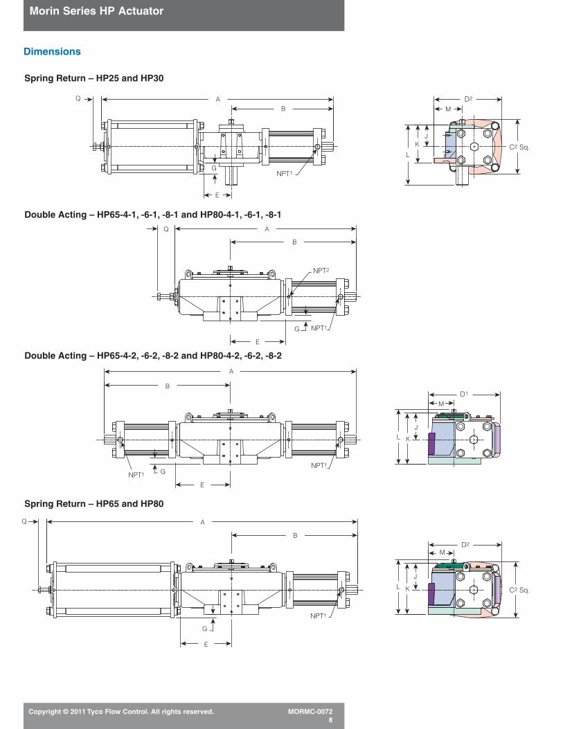
Dimensions
Double Acting – HP15-2-1, HP15-3-1
Double Acting – HP15-2-2
Spring Return – HP15
Double Acting – HP25-3-1, 4-1; HP30-4-1, -6-1, -8-1
Double Acting – HP25-3-2, -4-2; HP30-4-2, -6-2, -8-2
AQ
F
Q
Q
F
B
A
B
E
E
NPT1
NPT1
A
B
E
E
G
NPT1
A
B
E
G NPT1
A
B
G NPT1NPT1
NPT1
NPT2
NPT2
L
KJ
M
D1
C1 Sq.
L K
J
M
D1
C1 Sq.
L KJ
M
D2
C2 Sq.
Morin Series HP Actuator
Copyright © 2011 Tyco Flow Control. All rights reserved. MORMC-00728
Dimensions
Spring Return – HP25 and HP30
Double Acting – HP65-4-1, -6-1, -8-1 and HP80-4-1, -6-1, -8-1
Spring Return – HP65 and HP80
Double Acting – HP65-4-2, -6-2, -8-2 and HP80-4-2, -6-2, -8-2
L K
J
M
L
KJ
M
D2
D2
D1
C2 Sq.
C2 Sq.L K
J
M
AQ
B
E
G
AB
GNPT1
A
B
E
E
A
Q
Q
B
G
NPT1
NPT1
NPT1
NPT1
E
G
NPT2

Morin Series HP Actuator
Copyright © 2011 Tyco Flow Control. All rights reserved. MORMC-00729
Mounting Details
Model HP15 – Top and bottom of housing (symmetrical) – ISO 5211-F12
Model HP25 – Bottom of housing – ISO 5211-F16
0.998 Square0.995
0.251 +0.010 C’Bore x 0.209 +0.010 Deep-0.000 -0.000M6 Tap x 1/2" Deep
M5 x 0.8 Tap 0.37 Deep(4) Places as Shown
1.181 x 3.149" Rectangle(NAMUR Pattern)
2.000/1.994 Diameter Shaft1/2 Sq. x 3.19 Long Keyway
with 0.031 Radius Inside Keyway Corners(To be used w/1/2" x 33/16" key)
1/2 – 13 UNC * Tap x 0.65 Deep(4) Places as Shown on4.92 Dia. Bolt Circle(Morin Standard)
3/4 – 10 UNC ** Tap x 1.18 Deep(4) Places as Shown on6.50 Diameter Bolt Circle
B
A
A
Section A – A
Section B – BB
3.691.18
1.19
Sym.
0.94
0.157/0.160 Wide0.197/0.205 DeepDrive Slot
NAMUR DriveBoth Ends
Model HP25 and HP30 – Top of housing – mounting details
0.251 C’Bore x 0.209 Deep
M6 Tap x 1/2" Deep
M5 x 0.80 Tap x 3/8 Deep(4) Places on NAMUR Pattern
0.157/0.160 Wide x 0.197/0.205 DeepNAMUR Accessory Drive Slot
10 – 32 UNF *** Tap x 0.875 Deep(4) Places on Keystone Pattern
0.998/0.995Square
NAMUR Adapter
0.1970.205
HP25 3.68HP30 5.118HP25 3.149
HP30 3.68
1.181
1.61
1.18 +0.01-0.00
SHUT
SHUT
OP
EN
OP
EN
Model HP30 – Bottom of housing – ISO 5211-F30
3.000/2.994 Diameter Shaft3/4 Sq. x 3.75 Long Keyway with
0.031 Radius Inside Keyway Corners(To be used with 3/4" x 313/16" key)
3/4 – 10 UNC ** Tap x 1.18 Deep(8) Places as Shown on11.73 Diameter Bolt Circle
22.5°Typ.
C
C
Section C – C
1.185.31
4.56
+0.010 -0.000
+0.010 -0.000

Morin Series HP Actuator
Copyright © 2011 Tyco Flow Control. All rights reserved. MORMC-007210
Mounting Details
Metric Thread OptionMetric Tap Model Number
*M12 HP15
**M20 HP25 and HP30
***M5 HP25 and HP30
****M30 HP65
*****M36 HP80
Replace “U” with “M” in order number designation.
Model HP65 and HP80 – Top of housing – mounting details
Model HP65 – Bottom of housing – ISO 5211-F35
Model HP80 – Bottom of housing – ISO 5211-F48
0.251 C’Bore x 0.209 DeepM6 Tap x 1/2" Deep
Female Drive
6.250 +0.005 Dia. Bore x 12.5 Deep-0.000
1.501 +0.005 Rectangular Keyway-0.000
with 0.12 Radius Inside Keyway Corners(To be used with 11/2" x 1" key)
M5 x 0.80 Tap 3/8 Deep(4) Places on NAMUR Pattern1.181 x 3.149 Rectangle
0.157/0.160 Wide x 0.197/0.205 Deep
NAMUR Accessory Drive Slot
1– 8 UNC **** Tap x 13/4 Deep(8) Places as Shown on14.02 Diameter Bolt Circle
22.5°Typ.
45°
0.996/0.993Square
1.181
3.150
NAMUR Adapter
0.1970.205
1.18
E
E
Section E – E
1.18
Female Drive
8.750 +0.005 Dia. Bore x 17 Deep-0.000
2.000 +0.005 Rectangular Keyway-0.000
with 0.12 Radius Inside Keyway Corners(To be used with 2" x 11/2" key)
11/4 – 7 UNC ***** Tap x 21/2 Deep(12) Places as Shown on19.00 Diameter Bolt Circle
15.0°Typ.
45°
E
E
Section E – E
1.18
+0.010 -0.000
+0.010 -0.000
+0.010 -0.000

Manual OptionsTo provide the actuation package bestsuited for your application, the Morin lineoffers a full range of manual accessories.
Epoxy Painting (EX) Offshore rated,three-part coating system for high level of environmental protection.
Hydraulic Override (MHP) Manualoperation when power is lost. Includes speed controls.
Direct Mounting Cast AdaptersMany valve top works covered, includingsome ISO mounting. Assures economicbut correct mounting alignment.
High or Low Temperature RatingsStandard rating of -20°F to 210°F [-29°C to 99°C] covers most applications.Optional ratings down to -65°F [-54°C]and up to 300°F [149°C].
Morin Series HP Actuator
Copyright © 2011 Tyco Flow Control. All rights reserved. MORMC-007211
Model Numbering
HP - 30 U C - 4 - 1 - 370S080 - MHP
Model
HP – High Pressure Gas/hydraulic
Actuator Size
15 – 1.5" Moment Arm25 – 2.5" Moment Arm30 – 3.0" Moment Arm65 – 6.0" Moment Arm80 – 8.0" Moment Arm
Mounting Interface Bolting
U – UNC Mounting ThreadsM – Metric Mounting Threads
Yoke Design
(blank) – Symmetrical YokeC – Canted Yoke
Nominal Cylinder Bore (inches)
Number of Active Cylinders
1 – Single hydraulic cylinder on double acting or spring return2 – Two hydraulic cylinders on double acting
Function
Double Acting Spring ReturnDA See code from Morin Torque Book (MORMC-0333)
Fail Closed (CW) ends in "0" (i.e. 218S080)Fail Open (CCW) ends in "1" (i.e. 218S081)
Add on Option
(blank) – No options (standard configuration)
(Other options available - consult your sales representative}
DP1 Drain ports located 90 from std portDP2 Drain ports located 180 form std portsEX Epoxy paintG Grease fill - 3/4 fill in housingV High temp seals (Viton®)HS Hole through length of output shaft for
grease fitting of output shaftHD1 Hydraulic damper/speed control -
full strokeMHP Manual hydraulic overrideK K-Mass fire-proofingLT Low temp seals
P1M Prox prep - 5/8" w/Magnetic activatorP1 Prox prep - 5/8" w/Ferrous activatorP2 Prox prep - 18 mm w/Ferrous activatorP3 Prox prep - 12 mm w/Ferrous activatorSF Stainless steel fastenersSO Stainless steel output shaftSSP Stainless steel springsTB Teflon® bushing for output shaft and
piston/rodTBO Teflon® bushing for output shaftU U.H.M.W.P.E. Bushings
± °F/°C

Morin Series HP Actuator
Copyright © 2011 Tyco Flow Control. All rights reserved. MORMC-007212
www.tycoflowcontrol.com
Tyco Flow Control (TFC) provides the information herein in good faith but makes no representation as to its comprehensiveness or accuracy. This data sheet is intended only as a guide to TFC products and services. Individuals using this data sheet must exercise their independent judgment in evaluating product selection and determining product appropriateness for their particular purpose and system requirements. TFC MAKES NO REPRESENTATIONS OR WARRANTIES, EITHER EXPRESS OR IMPLIED, INCLUDING WITHOUT LIMITATION ANY WARRANTIES OF MERCHANTABILITY OR FITNESS FOR A PARTICULAR PURPOSE WITH RESPECT TO THE INFORMATION SET FORTH HEREIN OR THE PRODUCT(S) TO WHICH THE INFORMATION REFERS. ACCORDINGLY, TFC WILL NOT BE RESPONSIBLE FOR DAMAGES (OF ANY KIND OR NATURE, INCLUDING INCIDENTAL, DIRECT, INDIRECT, OR CONSEQUENTIAL DAMAGES) RESULTING FROM THE USE OF OR RELIANCE UPON THIS INFORMATION. Patents and Patents Pending in the U.S. and foreign countries. Tyco reserves the right to change product designs and specifications without notice. All registered trademarks are the property of their respective owners. Printed in the USA.
Also Available
The Series S Actuator (All Stainless)
The Series B and C Actuators
Setting an unrivaled standard in actuationat a price unexpectedly low for stainlesssteel.
• Up To 160 psig max operating pressure(see torque chart, MORMC-0333).
• Double acting break torques to 240,000 lb.in.
• Spring end torques to 104,125 lb.in.
For additional information, refer todatasheet MORMC-0024.
Setting a new standard in actuation at a price you’d expect from a commodityproduct.
• Up To 160 psig max operating pressure(see torque chart, MORMC-0333).
• Double acting break torques to1,400,000 lb.in.
• Spring end torques to 583,288 lb.in.
For additional information, refer to datasheet MORMC-0023.
18-8 Stainless Steel
Glass Filled Teflon®
17-4 PH Stainless Steel
316 Stainless SteelTeflon®
316 Stainless Steel316 Stainless Steel
316 Stainless Steel (Series B)Carbon Steel (Series C)
Ductile Iron
Sintered Bronzeor Teflon® composite
17-4 PH Stainless Steelor Ductile Iron
Chrome-plated SteelTeflon®