Embed Size (px)
Citation preview
Camin Srl – Viale della Regione Veneto 20 – 35127 – Padova – Italy – www.osip.it - 1 -
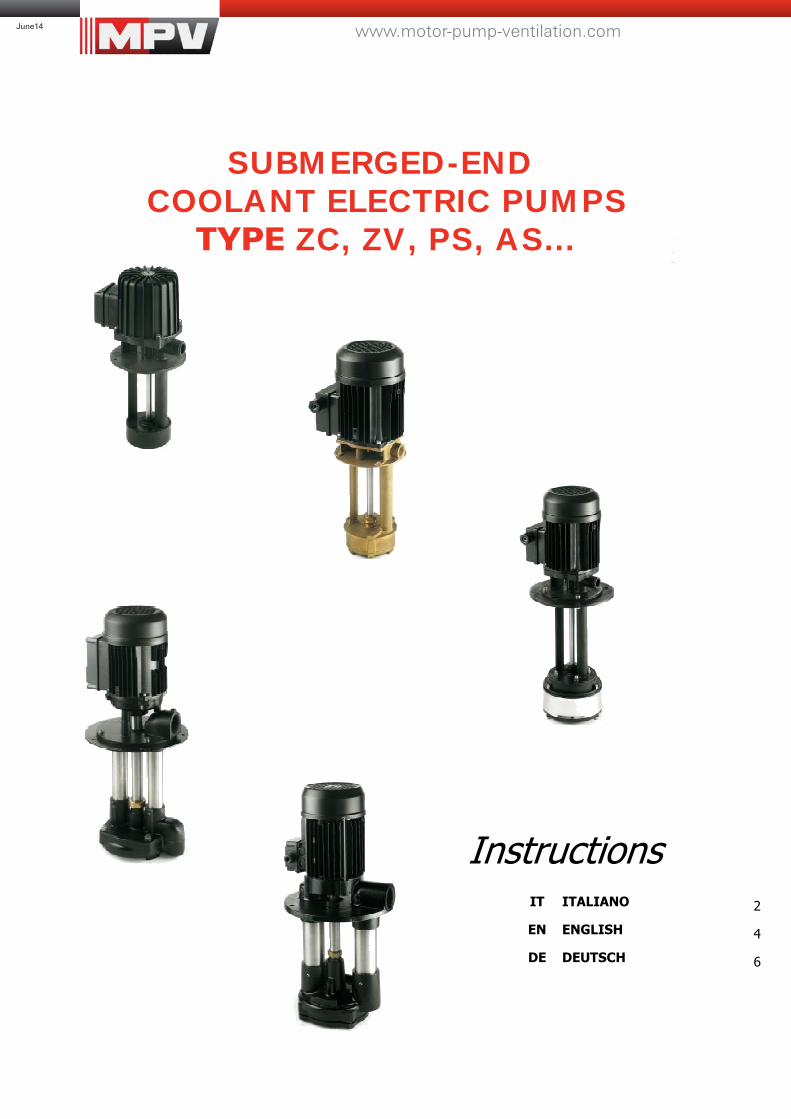
SUBMERGED-END
COOLANT ELECTRIC PUMPS TYPE ZC, ZV, PS, AS...
Instructions
IT ITALIANO
2
EN ENGLISH
4
DE DEUTSCH
6
www.motor-pump-ventilation.comJune14
- 2 -
ITALIANO
1. PREMESSA − Leggere attentamente le informazioni contenute in questo
opuscolo prima di mettere in funzione l’apparecchio. I danni all’apparecchio risultanti da un’errata messa in funzione faranno decadere automaticamente tutti i diritti di garanzia.
− Prestare particolare attenzione al capitolo che tratta la materia della sicurezza.
− Conservare questo opuscolo per consultarlo in caso di dubbi.
2. APPLICAZIONI
Queste pompe sono costruite principalmente per la circolazione di liquidi refrigeranti e miscele lubrificanti nelle macchine utensili, nelle macchine per la lavorazione del vetro e della plastica.
3. CONDIZIONI D’IMPIEGO − La temperatura del liquido non deve superare i 50° C. − Questi apparecchi sono idonei al pompaggio di liquidi
meccanicamente e chimicamente neutri. − Non utilizzare con idrocarburi o liquidi infiammabili. − L’utilizzo dell’apparecchio con liquidi contenenti sabbia o
altri materiali abrasivi ne può pregiudicare notevolmente la vita media. In questi casi si consiglia l’uso delle elettropompe tipo ZC/ZA le quali sono in grado di convogliare fluidi contenenti piccole impurità. Per una garanzia di lungo funzionamento è comunque meglio predisporre una adeguata decantazione o filtraggio ed eseguire una periodica pulizia della vasca.
− L’apparecchio non deve mai lavorare a secco.
L’utilizzo a secco danneggia le parti di tenuta e di guida.
4. SICUREZZA
L’utilizzo incauto di apparecchi elettrici a contatto con l’acqua possono ragionevolmente rappresentare un pericolo per l’incolumità delle persone. E’ perciò necessario seguire scrupolosamente le istruzioni che seguono. Nel caso rimanessero dei dubbi, contattare il produttore o un esperto elettricista. Se la pompa viene fornita senza cavo elettrico il collegamento dovrà essere eseguito a regola d’arte da un tecnico specializzato e in ottemperanza alle norme vigenti nello stato di utilizzo.
Non toccare la spina con le mani umide! Staccare sempre la corrente prima di maneggiare la pompa. Non tagliare né incidere il cavo elettrico.
L’impianto di alimentazione deve essere dotato di un interruttore differenziale con una capacità massima di 30 mA.
5. PREPARATIVI PER LA MESSA IN FUNZIONE L’installazione è un’operazione che può risultare di una certa complessità, pertanto deve essere effettuata da installatori competenti e autorizzati. Installare l’apparecchio in un luogo asciutto arieggiato e protetto da intemperie con temperatura ambientale massima di 40° C. − Per collegare la pompa è necessario utilizzare il minor
numero di raccordi sia dritti che curvi. − Il tubo di aspirazione può essere del tipo sia rigido che
flessibile avente una superficie interna liscia per ridurre al minimo le perdite di carico.
− Rimuovere eventuali impurità dalla pompa prima di metterla in funzione.
− Verificare la libera rotazione dell’albero motore agendo con un cacciavite nell’apposito intaglio posto nella parte posteriore del motore.
− Fissare adeguatamente mediante viti e dadi la flangia della pompa al coperchio della vasca (vedi fig. 2).
− Mantenere una distanza minima di 25mm tra il fondo della vasca e la sezione di aspirazione (vedi fig. 2).
− Riempire la vasca fino a coprire il corpo pompa immerso (vedi fig. 2).
6. MESSA IN FUNZIONE
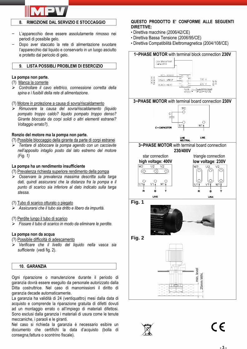
Prima della messa in funzione l’installatore deve assicurarsi che la tensione e la frequenza di alimentazione corrispondano ai dati di targa della pompa. Effettuare il collegamento elettrico con cavo adeguato e disporre i ponti della morsettiera come da schema riportato nel presente opuscolo. Nei motori trifase controllare che il senso di rotazione sia quello indicato dalla freccia posizionata nel copriventola. Durante il funzionamento assicurarsi che il livello del liquido all’interno della vasca non scenda sotto il livello minimo (vedi fig. 2).
7. PULIZIA E MANUTENZIONE
Staccare la tensione dall’apparecchio prima di effettuare qualsiasi manutenzione. Se l’apparecchio necessita di riparazione contattare uno specialista. Se la pompa rimane inutilizzata per lungo tempo è consigliabile svuotarla completamente, risciacquarla con acqua pulita e riporla in luogo asciutto. Per riutilizzarla ripetere le operazioni elencate in questo opuscolo.
- 3 -
8. RIMOZIONE DAL SERVIZIO E STOCCAGGIO − L’apparecchio deve essere assolutamente rimosso nei
periodi di possibile gelo. − Dopo aver staccato la rete di alimentazione svuotare
l’apparecchio dal liquido e conservarlo in un luogo asciutto e protetto dal pericolo di gelo.
9. LISTA POSSIBLI PROBLEMI DI ESERCIZIO
La pompa non parte. (?) Manca la corrente � Controllare il cavo elettrico, connessione corretta della
spina e i fusibili della rete di alimentazione. (?) Motore in protezione a causa di sovra/riscaldamento � Rimuovere la causa del sovra/riscaldamento (liquido
pompato troppo caldo? liquido pompato troppo denso? Girante bloccata da corpi solidi o altri elementi estranei? Voltaggio errato?).
Ronzio del motore ma la pompa non parte. (?) Possibile bloccaggio della girante da parte di corpi estranei � Tentare di sbloccare la pompa agendo con un cacciavite
nell’apposito intaglio posto dal lato estremo del motore (Fig. 1)
La pompa ha un rendimento insufficiente (?) Prevalenza richiesta superiore rendimento della pompa � Osservare la prevalenza massima descritta sulla targa
dati, quindi assicurarsi che la distanza fra la pompa e il punto di scarico sia inferiore al dato indicato sulla targa stessa.
(?) Tubo di scarico otturato o piegato � Assicurarsi che il tubo sia dritto e libero da impurità. (?) Perdite lungo il tubo di scarico � Fissare il tubo di scarico in modo da eliminare le perdite. La pompa non da acqua (?) Possibile difficoltà di adescamento � Verificare che il livello del liquido nella vasca sia
sufficiente (vedi fig. 2).
10. GARANZIA Ogni riparazione o manutenzione durante il periodo di garanzia dovrà essere eseguito da personale autorizzato dalla Ditta costruttrice. Nel caso di manomissioni il diritto di garanzia decade automaticamente. La garanzia ha validità di 24 (ventiquattro) mesi dalla data di acquisto e comprende la riparazione gratuita di difetti dovuti ad un montaggio errato o all’impiego di materiali difettosi. Sono esclusi dalla garanzia i materiali di usura come le tenute meccaniche, i paraoli e le giranti. Nel caso si richieda la garanzia è necessario esibire un documento che certifichi la data d’acquisto (bolla di consegna,fattura o scontrino fiscale).
QUESTO PRODOTTO E’ CONFORME ALLE SEGUENTI DIRETTIVE: • Direttiva macchine (2006/42/CE) • Direttiva Bassa Tensione (2006/95/CE) • Direttiva Compatibilità Elettromagnetica (2004/108/CE)
1~PHASE MOTOR with terminal block connection 230V
3~PHASE MOTOR with terminal board connection 230V
3~PHASE MOTOR with terminal board connection
230/400V star connection
high voltage: 400V
triangle connection low voltage: 230V
Fig. 1
Fig. 2
min
. lev
el25
mm
MIN
.
- 4 -
1. ASSUMPTION
− Please read these instructions carefully before use.
Damages resulting as consequence of instructions disregards will not be covered by manufacturer’s warranty.
− Please pay particular attention to the chapter
relating the safety instructions. − Save these instructions and refer to them anytime your
are in doubt.
2. APPLICATION These electric pumps have been engineered mainly to pump coolant liquids and lubricating mixtures into machines tool systems, machines for production of glass or plastic materials.
3. USE CONDITIONS − Liquid temperature must not exceed 50° C. − These pumps are suitable to be used in to chemically
neutral liquids. − Do not pump hydrocarbons or any other
inflammable liquid. − Pumping liquids containing sand or other abrasive
substances may reduce sensitively the life of the pumps. In this case we suggest pumps type ZC/ZA. In any case we recommend to assemble a strainer at the suction and clean the tank periodically.
− Never run pump dry. Dry runs may damage seals
and cause possible hazards of burns to persons handling the pump.
4. SAFETY
Careless use of electric appliances is always dangerous. Electric appliances used into water represent a potential hazards of electric shock. Thus we strongly recommend to pay full attention to the next instructions. If you still have doubts, contact an expert electrician or the manufacturer. Eventual connection of a power cord must performed by an expert electrician in accordance of the regulations is use in your Country
HAZARD! Do not touch the plug with wet hands! Switch off and unplug the pump before any maintenance. Do not cut or engrave the power cable.
Mains system must be provided of a residual current device of max 30 mA capacity.
5. INSTALLATION Installation may result to be fairly complicated therefore it should be carried out by a skilled person. Install your pump as close to the well as possible in a dry and environmentally protected place where temperature should not exceed 40° C. − Use the fewest possible elbows and fittings to connect
the pipe. − The pipe can be either rigid or flexible with smooth
internal surface in order to reduce at minimum the flow resistance.
− Remove all impurities from the pump housing before first use.
− Check the free motor rotation before start acting with a screwdriver into the groove of the fan side motor shaft.
− Sit the pump on a smooth surface and fix it with proper bolts in order to avoid vibrations.
− Fix properly the flange of the pump to the tank cover with screws and nuts (fig.2).
− Keep a minimum distance of 25 mm from the base of the tank and the suction hole of the pump (fig.2)
− Fill the tank till cover the submerged pump/end (fig.2).
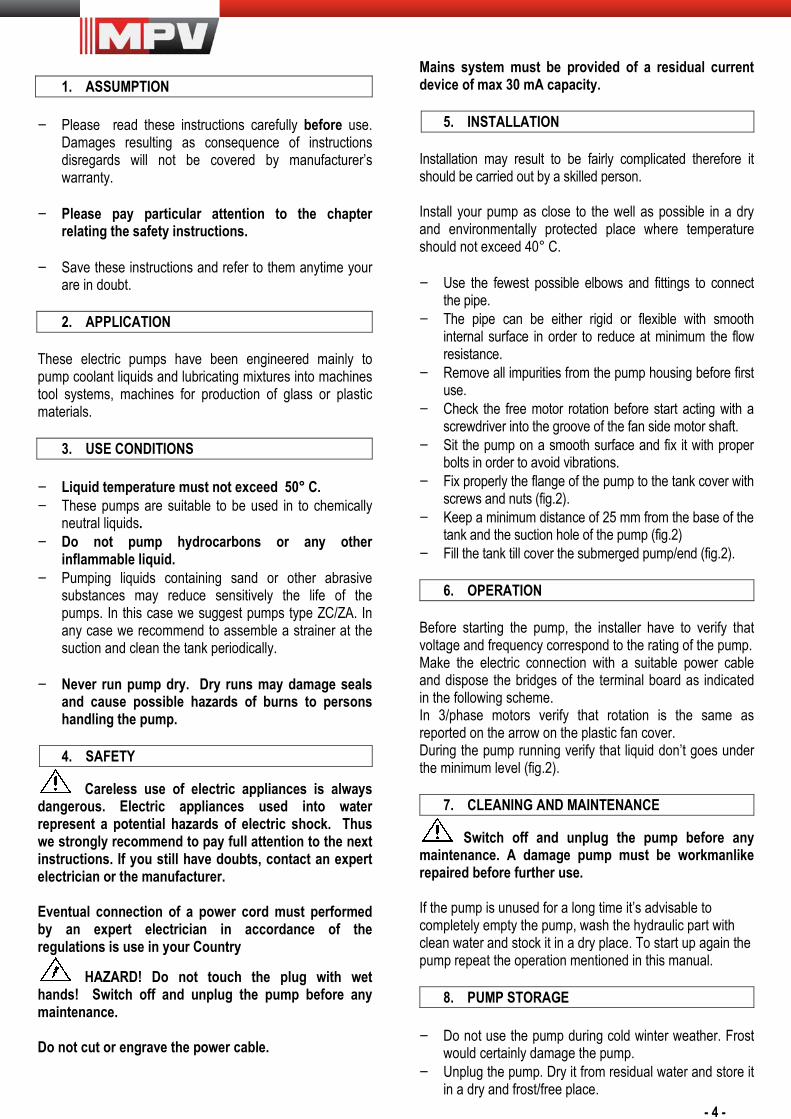
6. OPERATION Before starting the pump, the installer have to verify that voltage and frequency correspond to the rating of the pump. Make the electric connection with a suitable power cable and dispose the bridges of the terminal board as indicated in the following scheme. In 3/phase motors verify that rotation is the same as reported on the arrow on the plastic fan cover. During the pump running verify that liquid don’t goes under the minimum level (fig.2).
7. CLEANING AND MAINTENANCE
Switch off and unplug the pump before any maintenance. A damage pump must be workmanlike repaired before further use. If the pump is unused for a long time it’s advisable to completely empty the pump, wash the hydraulic part with clean water and stock it in a dry place. To start up again the pump repeat the operation mentioned in this manual.
8. PUMP STORAGE − Do not use the pump during cold winter weather. Frost
would certainly damage the pump. − Unplug the pump. Dry it from residual water and store it
in a dry and frost/free place.
- 5 -
9. TROUBLESHOOTING Motor does not start (?) Mains voltage missing � Check the power cable, proper plug connection and
mains fuse efficiency (?) Motor protector tripped for overheating � Remove cause for overheating (pumped liquid too hot?
Impeller blocked by foreign objects? Wrong voltage?). Motor hums but does not run. (?) Impeller blocked by foreign objects � Check the free rotation acting with a screwdriver into
the groove of the fan side motor shaft (Fig. 1) Pump works but water delivery is poor (?) Required head is too high compare the pump performance � Check characteristics in data plate and reduce distance
from pump and taps (in height) if necessary. (?) Pipe bended, too small in size or clogged � Straight pipe, use larger piping or remove objects
clogging (?) Pipes leak � Check connections . Pump does not deliver any water (?) Possible prime difficulties � Check if there is enough water in the tank(fig. 2).
10. CONDITIONS OF WARRANTY Any repairs or maintenance during the period covered by warranty must be carried out by authorised staff. In the event of the pump being tampered with the warranty automatically becomes void. The warranty comprises the free elimination of faults caused by errors in assembly or the use of faulty materials within 24 (twentyfour) months from the date of purchase. Materials subject to wear such as mechanical seals, oil seals and impellers are not included in the warranty. Should intervention under warranty be required it is necessary to show a document which proves the date of purchase (delivery note, invoice or receipt).
THIS PRODUCT COMPLIES WITH THE FOLLOWING DIRECTIVES: • Directive on machines (2006/42/CE) • Directive on low voltage (2006/95/CE) • Directive on electromagnetic compliance (2004/108/CE)
1~PHASE MOTOR with terminal block connection 230V
3~PHASE MOTOR with terminal board connection 230V
3~PHASE MOTOR with terminal board connection
230/400V star connection
high voltage: 400V
triangle connection low voltage: 230V
Fig. 1
Fig. 2
min
. lev
el25
mm
MIN
.
- 6 -
1. VORBEMERKUNGEN
− Lesen Sie bitte die in diesem Heft enthaltenen
Informationen aufmerksam durch, bevor Sie das Gerät in Betrieb setzen. Durch falsche Inbetriebsetzung entstehende Schäden bewirken automatisch den Verlust aller Garantierechte.
− Achten Sie besonders auf das Kapitel, das die Sicherheit betrifft.
− Bewahren Sie dieses Heft auf, um es in Zweifelsfällen zurate zu ziehen.
2. ANWENDUNGEN
Diese Pumpen werden hauptsächlich für den Umlauf von Kühlflüssigkeiten und Schmiermittelgemischen in Werkzeugmaschinen und Maschinen zur Glas/ und Kunststoffverarbeitung gebaut.
3. GEBRAUCHSBEDINGUNGEN − Die Flüssigkeitstemperatur darf 50°C nicht
überschreiten. − Diese Geräte sind für das Pumpen mechanisch und
chemisch neutraler Flüssigkeiten geeignet. − Nicht mit Kohlenwasserstoffen oder entflammbaren
Flüssigkeiten verwenden. − Die Benutzung des Geräts mit Flüssigkeiten, die Sand
oder andere abreibende Materialien enthalten, kann seine durchschnittliche Lebensdauer beträchtlich verringern. In diesen Fällen empfehlen wir die Verwendung der Elektropumpen vom Typ ZC/ZA, die in der Lage sind, kleine Unreinheiten enthaltende Flüssigkeiten zu leiten. Zur Garantie einer langen Betriebsdauer sollte jedenfalls eine geeignete Dekantierung oder Filterung vorgesehen und der Behälter in regelmäßigen Abständen gereinigt werden.
− Das Gerät darf niemals trocken arbeiten. Die
Trockenbenutzung beschädigt die Dichtungs/ und Führungsteile.
4. SICHERHEIT
Die unvorsichtige Benutzung elektrischer Geräte, die mit Wasser in Berührung kommen, kann eine Gefahr für die Unversehrtheit der Personen darstellen. Deshalb müssen die folgenden Anweisungen genau befolgt werden. In Zweifelsfällen wenden Sie sich bitte an den Hersteller oder an einen erfahrenen Elektriker. Wenn die Pumpe ohne Elektrokabel geliefert wird, ist der Anschluss von einem spezialisierten Techniker kunstgerecht und unter Beachtung der im Benutzungsland geltenden Vorschriften vorzunehmen.
Den Stecker nicht mit feuchten Händen berühren! Vor Handhabung der Pumpe immer den Strom abstellen. Das Elektrokabel nicht schneiden oder einritzen.
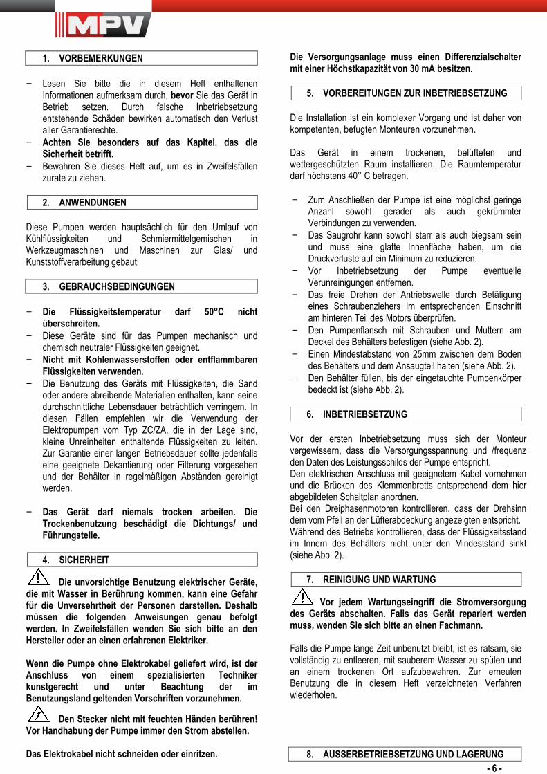
Die Versorgungsanlage muss einen Differenzialschalter mit einer Höchstkapazität von 30 mA besitzen.
5. VORBEREITUNGEN ZUR INBETRIEBSETZUNG Die Installation ist ein komplexer Vorgang und ist daher von kompetenten, befugten Monteuren vorzunehmen. Das Gerät in einem trockenen, belüfteten und wettergeschützten Raum installieren. Die Raumtemperatur darf höchstens 40° C betragen. − Zum Anschließen der Pumpe ist eine möglichst geringe
Anzahl sowohl gerader als auch gekrümmter Verbindungen zu verwenden.
− Das Saugrohr kann sowohl starr als auch biegsam sein und muss eine glatte Innenfläche haben, um die Druckverluste auf ein Minimum zu reduzieren.
− Vor Inbetriebsetzung der Pumpe eventuelle Verunreinigungen entfernen.
− Das freie Drehen der Antriebswelle durch Betätigung eines Schraubenziehers im entsprechenden Einschnitt am hinteren Teil des Motors überprüfen.
− Den Pumpenflansch mit Schrauben und Muttern am Deckel des Behälters befestigen (siehe Abb. 2).
− Einen Mindestabstand von 25mm zwischen dem Boden des Behälters und dem Ansaugteil halten (siehe Abb. 2).
− Den Behälter füllen, bis der eingetauchte Pumpenkörper bedeckt ist (siehe Abb. 2).
6. INBETRIEBSETZUNG
Vor der ersten Inbetriebsetzung muss sich der Monteur vergewissern, dass die Versorgungsspannung und /frequenz den Daten des Leistungsschilds der Pumpe entspricht. Den elektrischen Anschluss mit geeignetem Kabel vornehmen und die Brücken des Klemmenbretts entsprechend dem hier abgebildeten Schaltplan anordnen. Bei den Dreiphasenmotoren kontrollieren, dass der Drehsinn dem vom Pfeil an der Lüfterabdeckung angezeigten entspricht. Während des Betriebs kontrollieren, dass der Flüssigkeitsstand im Innern des Behälters nicht unter den Mindeststand sinkt (siehe Abb. 2).
7. REINIGUNG UND WARTUNG
Vor jedem Wartungseingriff die Stromversorgung des Geräts abschalten. Falls das Gerät repariert werden muss, wenden Sie sich bitte an einen Fachmann. Falls die Pumpe lange Zeit unbenutzt bleibt, ist es ratsam, sie vollständig zu entleeren, mit sauberem Wasser zu spülen und an einem trockenen Ort aufzubewahren. Zur erneuten Benutzung die in diesem Heft verzeichneten Verfahren wiederholen.
8. AUSSERBETRIEBSETZUNG UND LAGERUNG
- 7 -
− In den Zeiten, in denen Frostgefahr besteht, muss das
Gerät unbedingt außer Betrieb gesetzt werden. − Nach Trennen der Stromversorgung das Gerät von der
Flüssigkeit leeren und an einem trockenen, vor Frost geschützten Ort aufbewahren.
9. LISTE MÖGLICHER BETRIEBSSTÖRUNGEN
Die Pumpe läuft nicht an. (?) Kein Strom vorhanden � Das Elektrokabel, den richtigen Anschluss des Steckers
und die Sicherungen des Versorgungsnetzes kontrollieren. (?) Motorschutz ausgelöst wegen Heißlaufen � Die Ursache des Heißlaufens beseitigen (gepumpte
Flüssigkeit zu heiß? Gepumpte Flüssigkeit zu dickflüssig? Laufrad durch Festkörper oder andere Fremdkörper blockiert? Falsche Spannung?).
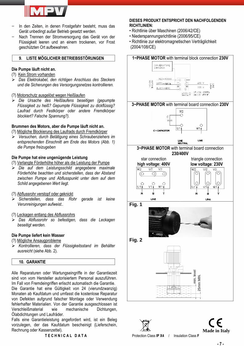
Brummen des Motors, aber die Pumpe läuft nicht an. (?) Mögliche Blockierung des Laufrads durch Fremdkörper � Versuchen, durch Betätigung eines Schraubenziehers im
entsprechenden Einschnitt am Ende des Motors (Abb. 1) die Pumpe freizugeben
Die Pumpe hat eine ungenügende Leistung (?) Verlangte Förderhöhe höher als die Leistung der Pumpe � Die auf dem Leistungsschild angegebene maximale
Förderhöhe beachten und sicherstellen, dass der Abstand zwischen Pumpe und Abflusspunkt unter dem auf dem Schild angegebenen Wert liegt.
(?) Abflussrohr verstopf oder geknickt � Sicherstellen, dass das Rohr gerade ist keine
Verunreinigungen aufweist.. (?) Leckagen entlang des Abflussrohrs � Das Abflussrohr so befestigen, dass die Leckagen
beseitigt werden. Die Pumpe liefert kein Wasser (?) Mögliche Ansaugprobleme � Kontrollieren, dass der Flüssigkeitsstand im Behälter
ausreicht (siehe Abb. 2).
10. GARANTIE Alle Reparaturen oder Wartungseingriffe in der Garantiezeit sind von vom Hersteller autorisiertem Personal auszuführen. Im Fall von Fremdeingriffen erlischt automatisch die Garantie. Die Garantie hat eine Gültigkeit von 24 (vierundzwanzig) Monaten ab Kaufdatum und umfasst die kostenlose Reparatur von Defekten aufgrund falscher Montage oder Verwendung fehlerhafter Materialien. Von der Garantie ausgeschlossen ist Verschleißmaterial wie mechanische Dichtungen, Ölabdichtungen und Laufräder. Falls eine Garantieleistung angefordert wird, ist ein Beleg vorzulegen, der das Kaufdatum bescheinigt (Lieferschein, Rechnung oder Kassenzettel).
DIESES PRODUKT ENTSPRICHT DEN NACHFOLGENDEN RICHTLINIEN: • Richtlinie über Maschinen (2006/42/CE) • Niederspannungsrichtlinie (2006/95/CE) • Richtlinie zur elektromagnetischen Verträglichkeit (2004/108/CE)
1~PHASE MOTOR with terminal block connection 230V
3~PHASE MOTOR with terminal board connection 230V
3~PHASE MOTOR with terminal board connection
230/400V star connection
high voltage: 400V
triangle connection low voltage: 230V
Fig. 1
Fig. 2
min
. lev
el25
mm
MIN
.
Made in Italy T E C H N I C A L D A T A Protection Class IP X4 / Insulation Class F
- 8 -
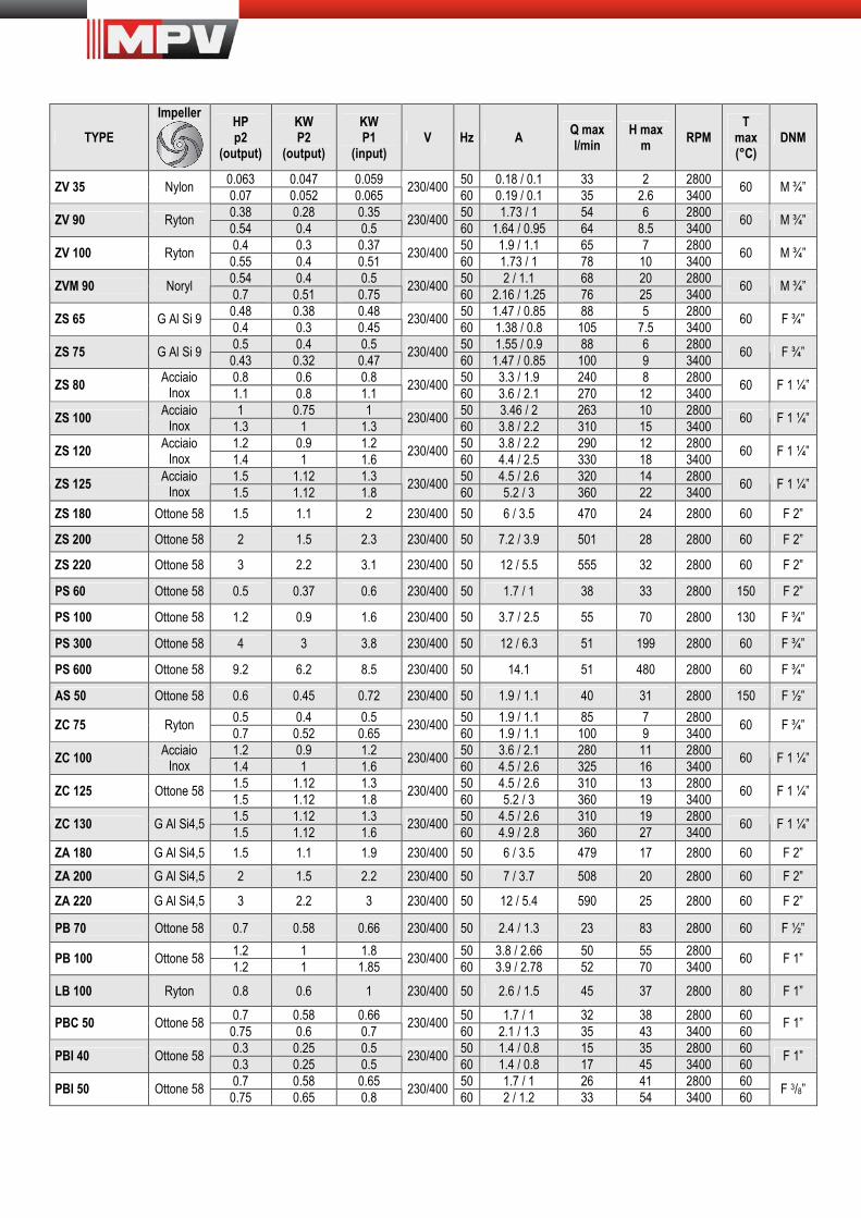
TYPE
Impeller
HP p2
(output)
KW P2
(output)
KW P1
(input) V Hz A
Q max l/min
H max m
RPM T
max (°C)
DNM
0.063 0.047 0.059 50 0.18 / 0.1 33 2 2800 ZV 35 Nylon
0.07 0.052 0.065 230/400
60 0.19 / 0.1 35 2.6 3400 60 M ¾”
0.38 0.28 0.35 50 1.73 / 1 54 6 2800 ZV 90 Ryton
0.54 0.4 0.5 230/400
60 1.64 / 0.95 64 8.5 3400 60 M ¾”
0.4 0.3 0.37 50 1.9 / 1.1 65 7 2800 ZV 100 Ryton
0.55 0.4 0.51 230/400
60 1.73 / 1 78 10 3400 60 M ¾”
0.54 0.4 0.5 50 2 / 1.1 68 20 2800 ZVM 90 Noryl
0.7 0.51 0.75 230/400
60 2.16 / 1.25 76 25 3400 60 M ¾”
0.48 0.38 0.48 50 1.47 / 0.85 88 5 2800 ZS 65 G Al Si 9
0.4 0.3 0.45 230/400
60 1.38 / 0.8 105 7.5 3400 60 F ¾”
0.5 0.4 0.5 50 1.55 / 0.9 88 6 2800 ZS 75 G Al Si 9
0.43 0.32 0.47 230/400
60 1.47 / 0.85 100 9 3400 60 F ¾”
0.8 0.6 0.8 50 3.3 / 1.9 240 8 2800 ZS 80
Acciaio Inox 1.1 0.8 1.1
230/400 60 3.6 / 2.1 270 12 3400
60 F 1 ¼”
1 0.75 1 50 3.46 / 2 263 10 2800 ZS 100
Acciaio Inox 1.3 1 1.3
230/400 60 3.8 / 2.2 310 15 3400
60 F 1 ¼”
1.2 0.9 1.2 50 3.8 / 2.2 290 12 2800 ZS 120
Acciaio Inox 1.4 1 1.6
230/400 60 4.4 / 2.5 330 18 3400
60 F 1 ¼”
1.5 1.12 1.3 50 4.5 / 2.6 320 14 2800 ZS 125
Acciaio Inox 1.5 1.12 1.8
230/400 60 5.2 / 3 360 22 3400
60 F 1 ¼”
ZS 180 Ottone 58 1.5 1.1 2 230/400 50 6 / 3.5 470 24 2800 60 F 2”
ZS 200 Ottone 58 2 1.5 2.3 230/400 50 7.2 / 3.9 501 28 2800 60 F 2”
ZS 220 Ottone 58 3 2.2 3.1 230/400 50 12 / 5.5 555 32 2800 60 F 2”
PS 60 Ottone 58 0.5 0.37 0.6 230/400 50 1.7 / 1 38 33 2800 150 F 2”
PS 100 Ottone 58 1.2 0.9 1.6 230/400 50 3.7 / 2.5 55 70 2800 130 F ¾”
PS 300 Ottone 58 4 3 3.8 230/400 50 12 / 6.3 51 199 2800 60 F ¾”
PS 600 Ottone 58 9.2 6.2 8.5 230/400 50 14.1 51 480 2800 60 F ¾”
AS 50 Ottone 58 0.6 0.45 0.72 230/400 50 1.9 / 1.1 40 31 2800 150 F ½”
0.5 0.4 0.5 50 1.9 / 1.1 85 7 2800 ZC 75 Ryton
0.7 0.52 0.65 230/400
60 1.9 / 1.1 100 9 3400 60 F ¾”
1.2 0.9 1.2 50 3.6 / 2.1 280 11 2800 ZC 100
Acciaio Inox 1.4 1 1.6
230/400 60 4.5 / 2.6 325 16 3400
60 F 1 ¼”
1.5 1.12 1.3 50 4.5 / 2.6 310 13 2800 ZC 125 Ottone 58
1.5 1.12 1.8 230/400
60 5.2 / 3 360 19 3400 60 F 1 ¼”
1.5 1.12 1.3 50 4.5 / 2.6 310 19 2800 ZC 130 G Al Si4,5
1.5 1.12 1.6 230/400
60 4.9 / 2.8 360 27 3400 60 F 1 ¼”
ZA 180 G Al Si4,5 1.5 1.1 1.9 230/400 50 6 / 3.5 479 17 2800 60 F 2”
ZA 200 G Al Si4,5 2 1.5 2.2 230/400 50 7 / 3.7 508 20 2800 60 F 2”
ZA 220 G Al Si4,5 3 2.2 3 230/400 50 12 / 5.4 590 25 2800 60 F 2”
PB 70 Ottone 58 0.7 0.58 0.66 230/400 50 2.4 / 1.3 23 83 2800 60 F ½”
1.2 1 1.8 50 3.8 / 2.66 50 55 2800 PB 100 Ottone 58
1.2 1 1.85 230/400
60 3.9 / 2.78 52 70 3400 60 F 1”
LB 100 Ryton 0.8 0.6 1 230/400 50 2.6 / 1.5 45 37 2800 80 F 1”
0.7 0.58 0.66 50 1.7 / 1 32 38 2800 60 PBC 50 Ottone 58
0.75 0.6 0.7 230/400
60 2.1 / 1.3 35 43 3400 60 F 1”
0.3 0.25 0.5 50 1.4 / 0.8 15 35 2800 60 PBI 40 Ottone 58
0.3 0.25 0.5 230/400
60 1.4 / 0.8 17 45 3400 60 F 1”
0.7 0.58 0.65 50 1.7 / 1 26 41 2800 60 PBI 50 Ottone 58
0.75 0.65 0.8 230/400
60 2 / 1.2 33 54 3400 60 F 3/8”


![University of Zurich Zurich Open ... · sione del Bene. Così Socrate afferma: “predìco che prima di saperlo [il Bene] nessuno potrà adeguatamente conoscere quelle stesse cose](https://img.pdfslide.us/doc/110x75/5c6a376b09d3f20f298c3e01/university-of-zurich-zurich-open-sione-del-bene-cosi-socrate-afferma.jpg)
![Management HowTo Business plan: progettare e …...2016/09/29 · Tasso di conversione dell’e—commerce per rispettare il CPA massimo [Fissare] Sezione Informatica-Telecomunicazioni](https://img.pdfslide.us/doc/110x75/5f6751650a15f5089e166dd8/management-howto-business-plan-progettare-e-20160929-tasso-di-conversione.jpg)