Embed Size (px)
Citation preview
Series MPI-822H220W PFC INDUSTRIAL ATX POWER SUPPLY
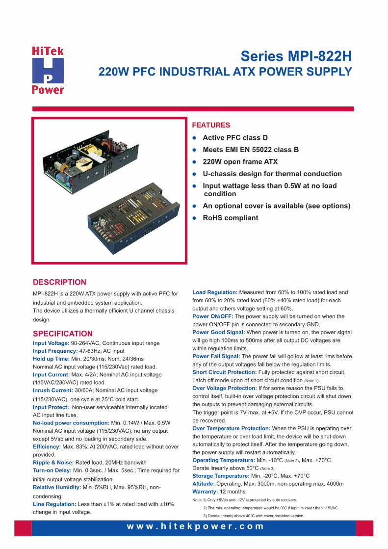
FEATURES
l
l
l
l
l
l
l
Active PFC class D
Meets EMI EN 55022 class B
220W open frame ATX
An optional cover is available (see options)
RoHS compliant
U-chassis design for thermal conduction
Input wattage less than 0.5W at no load condition
DESCRIPTION
MPI-822H is a 220W ATX power supply with active PFC for
industrial and embedded system application.
The device utilizes a thermally efficient U channel chassis
design.
90
Min. 20
Max. 4/2
Min. 0.14W / Max. 0.5W
Min. 0.3sec. / Max. 5sec.; Time required for
initial output voltage stabilization.
Min. 5%RH, Max. 95%RH, non-
condensing
Input Voltage:
Inrush Current:
Input Protect:
No-load power consumption:
Efficiency:
Turn-on Delay:
Line Regulation:
-264VAC, Continuous input range
47-63Hz, AC input
/30ms; Nom. 24/36ms
Nominal AC input voltage (115/230Vac) rated load.
A; Nominal AC input voltage
(115VAC/230VAC) rated load.
30/60A; Nominal AC input voltage
(115/230VAC), one cycle at 25°C cold start.
Non-user serviceable internally located
AC input line fuse.
Nominal AC input voltage (115/230VAC), no any output
except 5Vsb and no loading in secondary side.
Max. 83%; At 200VAC, rated load without cover
provided.
Rated load, 20MHz bandwith
Less than ±1% at rated load with ±10%
change in input voltage.
Input Frequency:
Hold up Time:
Input Current:
Ripple & Noise:
Relative Humidity:
w w w . h i t e k p o w e r . c o m
SPECIFICATION
Load Regulation:
Power ON/OFF:
Power Good Signal:
Power Fail Signal:
Short Circuit Protection:
Over Voltage Protection:
Over Temperature Protection:
Operating Temperature:
Storage Temperature:
Altitude:
Warranty:
Measured from 60% to 100% rated load and
from 60% to 20% rated load (60% ±40% rated load) for each
output and others voltage setting at 60%.
The power supply will be turned on when the
power ON/OFF pin is connected to secondary GND.
When power is turned on, the power signal
will go high 100ms to 500ms after all output DC voltages are
within regulation limits.
The power fail will go low at least 1ms before
any of the output voltages fall below the regulation limits.
Fully protected against short circuit.
Latch off mode upon of short circuit condition (Note 1).
If for some reason the PSU fails to
control itself, built-in over voltage protection circuit will shut down
the outputs to prevent damaging external circuits.
The trigger point is 7V max. at +5V. If the OVP occur, PSU cannot
be recovered.
When the PSU is operating over
the temperature or over load limit, the device will be shut down
automatically to protect itself. After the temperature going down,
the power supply will restart automatically.
Min. -10°C (Note 2), Max. +70°C
Derate linearly above 50°C (Note 3).
Min. -20°C, Max. +70°C
Operating: Max. 3000m, non-operating max. 4000m
12 months
Note: 1) Only +5Vsb and -12V is protected by auto recovery.
2) The min. operating temperature would be 0°C if input is lower than 115VAC.
3) Derate linearly above 40°C with cover provided version.
Series MPI-822H220W PFC INDUSTRIAL ATX POWER SUPPLY
SPECIFICATION
Approvals:
EMI (Note 1):
EMS:
UL 60950-1, 2nd edition UL approved
CSA C22.2 No. 60950-1-07, 2nd edition cUL approved
EN 60950-1, 2nd edition Declaration of conformity
Input to output, Min. 3000VAC
EN 61000-3-2 & EN 610003-3 - Class D
EN 55022 / CISPR 22 & FCC Part 15 - Class B
IEC 61000-4-2 8kV air discharge, 6kV contact discharge - Criteria A
IEC 61000-4-3 3V/m - Criteria A
IEC 61000-4-4 2kV line & PE - Criteria A
IEC 61000-4-5 L-N: ± 1kV, L/N-PE: 2kV - Criteria A
IEC 61000-4-6 10V - Criteria A
IEC 61000-4-8 10A/M - Criteria A
IEC 61000-4-11 Voltage dips > 95%, 0.5 cycle - Criteria A
Voltage dips > 30%, 25 cycles - Criteria A
Voltage interruptions > 95%, 250 cycles - Criteria B
Hi-Pot:
PFC:
NOTE
1) As this is a component power supply, it needs to be installed in a suitable enclosure to pass the EMI/EMC tests. The final assembly has to comply with the valid EMI/EMC and safety regulations.
w w w . h i t e k p o w e r . c o m
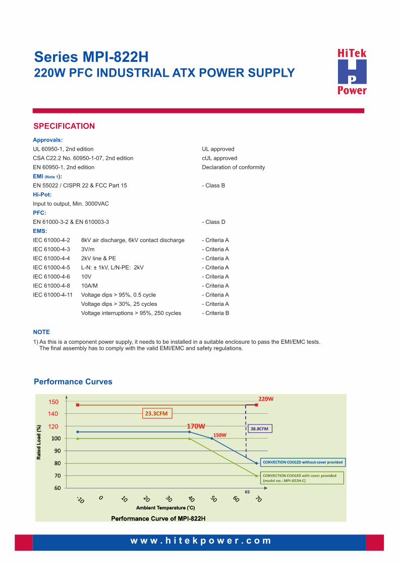
Performance Curves
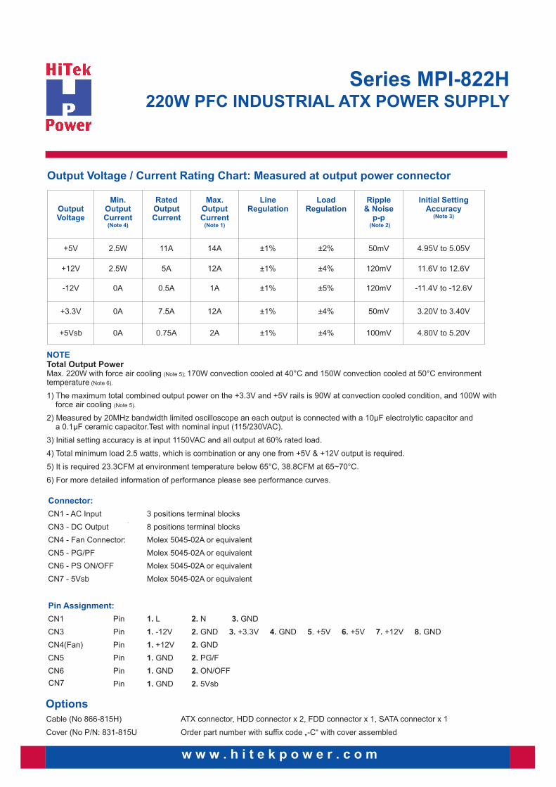
Output Voltage / Current Rating Chart: Measured at output power connector
w w w . h i t e k p o w e r . c o m
Series MPI-822H220W PFC INDUSTRIAL ATX POWER SUPPLY
Output Voltage
Min. OutputCurrent
(Note 4)
Rated Output Current
Max. OutputCurrent
(Note 1)
Line Regulation
Load Regulation
Ripple & Noise
p-p (Note 2)
Initial SettingAccuracy
(Note 3)
+5V 2.5W 11A 14A ±1% ±2% 50mV 4.95V to 5.05V
+12V 2.5W 5A 12A ±1% ±4% 120mV 11.6V to 12.6V
-12V 0A 0.5A 1A ±1% ±5% 120mV -11.4V to -12.6V
+3.3V 0A 7.5A 12A ±1% ±4% 50mV 3.20V to 3.40V
+5Vsb 0A 0.75A 2A ±1% ±4% 100mV 4.80V to 5.20V
NOTETotal Output PowerMax. 220W with force air cooling (Note 5); 170W convection cooled at 40°C and 150W convection cooled at 50°C environment temperature (Note 6).
1) The maximum total combined output power on the +3.3V and +5V rails is 90W at convection cooled condition, and 100W with force air cooling (Note 5).
2) Measured by 20MHz bandwidth limited oscilloscope an each output is connected with a 10µF electrolytic capacitor and a 0.1µF ceramic capacitor.Test with nominal input (115/230VAC).
3) Initial setting accuracy is at input 1150VAC and all output at 60% rated load.
4) Total minimum load 2.5 watts, which is combination or any one from +5V & +12V output is required.
5) It is required 23.3CFM at environment temperature below 65°C, 38.8CFM at 65~70°C.
6) For more detailed information of performance please see performance curves.
Options
Cable (No 866-815H) ATX connector, HDD connector x 2, FDD connector x 1, SATA connector x 1
Cover (No P/N: 831-815U Order part number with suffix code „-C“ with cover assembled
CN7
w w w . h i t e k p o w e r . c o m
Series MPI-822H220W PFC INDUSTRIAL ATX POWER SUPPLY
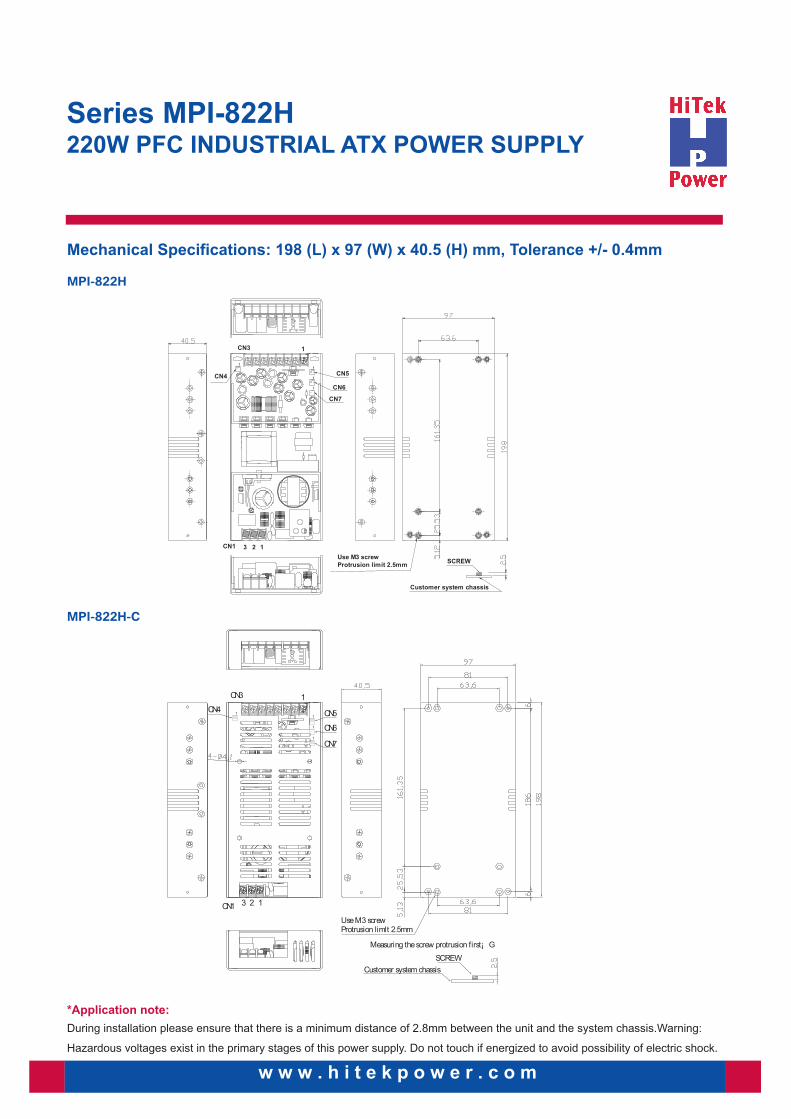
Mechanical Specifications: 198 (L) x 97 (W) x 40.5 (H) mm, Tolerance +/- 0.4mm
MPI-822H
1
1
1CN1 23
CN3 1
CN4 CN5
CN6
CN7
Use M3 screwProtrusion limlt 2.5mm
SCREW
Customer system chassis
Measuring the screw protrusion first¡ G
1
1
MPI-822H-C
CN1 3 2 1
CN3
CN4 CN5
CN6
CN7
1
1
1
Use M3 screwProtrusion limit 2.5mm
SCREW
Customer system chassis
1
1
*Application note:
During installation please ensure that there is a minimum distance of 2.8mm between the unit and the system chassis.Warning:
Hazardous voltages exist in the primary stages of this power supply. Do not touch if energized to avoid possibility of electric shock.
GERMANY
E-Mail: [email protected]
Joh.-Friedr.-Boettger-Str. 2163322 Roedermark
Phone +49 6074 69285-0Fax: +49 6074 69285-10
Revision 02/2014
w w w . h i t e k p o w e r . c o m