Embed Size (px)
Citation preview
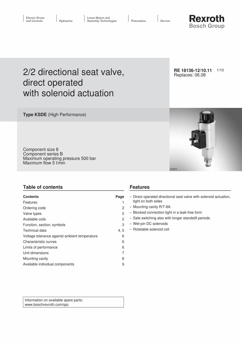
1/102/2 directional seat valve, direct operated with solenoid actuation
Type KSDE (High Performance)
Component size 8Component series BMaximum operating pressure 500 barMaximum flow 5 l/min
RE 18136-12/10.11Replaces: 06.08
Table of contents
Contents PageFeatures 1Ordering code 2Valve types 2Available coils 2Function, section, symbols 3Technical data 4, 5Voltage tolerance against ambient temperature 6Characteristic curves 6Limits of performance 6Unit dimensions 7Mounting cavity 8Available individual components 9
Features
– Direct operated directional seat valve with solenoid actuation, tight on both sides
– Mounting cavity R/T-8A– Blocked connection tight in a leak-free form– Safe switching also with longer standstill periods– Wet-pin DC solenoids– Rotatable solenoid coil
H7077
Information on available spare parts: www.boschrexroth.com/spc
InhaltTable of contents 1Features 1Ordering code (valve without coil) 1) 2
Valve types (without coil) 1) 2
Available coils (separate order) 1) 2
Function, section, symbols 3Technical data (For applications outside these parameters, please consult us!) 4Technical data (For applications outside these parameters, please consult us!) 5Voltage tolerance against ambient temperature; duty cycle 6Characteristic curves (measured with HLP46, ϑoil = 40 °C ± 5 °C and 24 V coil) 6Limits of performance (measured with HLP46, ϑoil = 40 °C ± 5 °C and 24 V coil) 6Unit dimensions (dimensions in mm) 7
Mounting cavity R/T-8A; 2 main ports; thread M16 x 1.5 (dimen-
sions in mm) 8Available individual components 9Notes 10Notes 11Notes 12
KSDE RE 18136-12/10.112/10 Bosch Rexroth AG Hydraulics
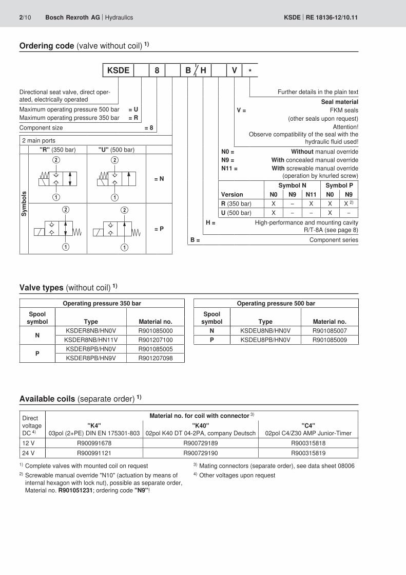
Ordering code (valve without coil) 1)
Directional seat valve, direct oper-ated, electrically operated
Maximum operating pressure 500 bar = UMaximum operating pressure 350 bar = RComponent size = 8
2 main ports"R" (350 bar) "U" (500 bar)
Sym
bols
2
1
2
1
= N
2
1
2
1
= P
Further details in the plain textSeal material
V = FKM seals(other seals upon request)
Attention! Observe compatibility of the seal with the
hydraulic fluid used!N0 = Without manual overrideN9 = With concealed manual override N11 = With screwable manual override
(operation by knurled screw)
VersionSymbol N Symbol P
N0 N9 N11 N0 N9R (350 bar) X – X X X 2)
U (500 bar) X – – X –H = High-performance and mounting cavity
R/T-8A (see page 8) B = Component series
KSDE 8 B H V *
Operating pressure 500 barSpool
symbol Type Material no.N KSDEU8NB/HN0V R901085007P KSDEU8PB/HN0V R901085009
Available coils (separate order) 1)
Direct voltage DC 4)
Material no. for coil with connector 3)
"K4" 03pol (2+PE) DIN EN 175301-803
"K40" 02pol K40 DT 04-2PA, company Deutsch
"C4" 02pol C4/Z30 AMP Junior-Timer
12 V R900991678 R900729189 R90031581824 V R900991121 R900729190 R900315819
1) Complete valves with mounted coil on request2) Screwable manual override "N10" (actuation by means of
internal hexagon with lock nut), possible as separate order, Material no. R901051231; ordering code "N9"!
Valve types (without coil) 1)
Operating pressure 350 barSpool
symbol Type Material no.
NKSDER8NB/HN0V R901085000KSDER8NB/HN11V R901207100
PKSDER8PB/HN0V R901085005KSDER8PB/HN9V R901207098
3) Mating connectors (separate order), see data sheet 080064) Other voltages upon request
4
2
1
23
1
(P)
(A)
5
6
RE 18136-12/10.11 KSDE 3/10Hydraulics Bosch Rexroth AG
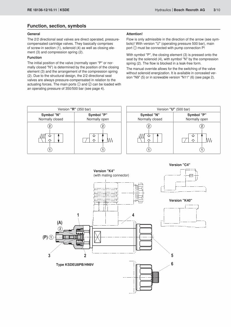
Function, section, symbolsGeneralThe 2/2 directional seat valves are direct operated, pressure-compensated cartridge valves. They basically comprises of screw-in section (1), solenoid (4) as well as closing ele-ment (3) and compression spring (2).FunctionThe initial position of the valve (normally open "P" or nor-mally closed "N") is determined by the position of the closing element (3) and the arrangement of the compression spring (2). Due to the structural design, the 2/2 directional seat valves are always pressure-compensated in relation to the actuating forces. The main ports ① and ② can be loaded with an operating pressure of 350/500 bar (see page 4).
Attention!Flow is only admissible in the direction of the arrow (see sym-bols)! With version "U" (operating pressure 500 bar), main port ① must be connected with pump connection P!
With symbol "P", the closing element (3) is pressed onto the seat by the solenoid (4), with symbol "N" by the compression spring (2). The flow is blocked in a leak-free form.The manual override allows for the the switching of the valve without solenoid energization. It is available in concealed ver-sion "N9" (5) or in screwable version "N11" (6) (see page 2).
Version "R" (350 bar)Symbol "N"
Normally closedSymbol "P"
Normally open
2
1
2
1
Version "U" (500 bar)Symbol "N"
Normally closedSymbol "P"
Normally open
2
1
2
1
Version "K4" (with mating connector)
Version "C4"
Version "K40"
Type KSDEU8PB/HN9V

KSDE RE 18136-12/10.114/10 Bosch Rexroth AG Hydraulics
Technical data (For applications outside these parameters, please consult us!)
hydraulicMaximum operating pressure – Version "U" bar 500 (at all ports if P ≥ A; for design reasons)
– Version "R" bar 350 (at all ports)Maximum flow – Version "U" l/min 3 (see limits of performance page 6)
– Version "R" l/min 5 (see limits of performance page 6)Hydraulic fluid See table belowHydraulic fluid temperature range °C –40 to +80Viscosity range mm2/s 4 to 500Maximum permitted degree of contamination of the hydraulic fluid - cleanliness class according to ISO 4406 (c)
Class 20/18/15 1)
Load cycles – Version "R" (350 bar) 10 million – Version "U" (500 bar) 5 million
generalWeight – Valve kg 0.30
– Coil kg 0.25Installation position AnyAmbient temperature range °C –40 to +110
1) The cleanliness classes specified for the components must be adhered to in hydraulic systems. Effective filtration pre-vents faults and at the same time increases the service life of the components.
For the selection of the filters see www.boschrexroth.com/filter.
Hydraulic fluid Classification Suitable sealing materials StandardsMineral oils and related hydrocarbons HL, HLP, HLPD, HVLP, HVLPD FKM DIN 51524
Environmentally compatible– Insoluble in water
HETG FKMISO 15380
HEES FKM– Soluble in water HEPG FKM ISO 15380
Flame-resistant– Water-free HFDU, HFDR FKM ISO 12922– Water-containing HFAS FKM ISO 12922
Important information on hydraulic fluids!– For more information and data on the use of other hydrau-
lic fluids refer to data sheet 90220 or contact us!– There may be limitations regarding the technical valve
data (temperature, pressure range, service life, mainte-nance intervals, etc.)!
– The flash point of the process and operating medium used must be 40 K higher than the maximum solenoid sur-face temperature.
– Flame-resistant – water-containing: Maximum pressure differential per control edge 175 bar, otherwise, increased cavitation erosion! Tank pre-loading < 1 bar or > 20 % of the pressure differential. The pressure peaks should not exceed the maximum operating pressures!
– Environmentally compatible: When using environmen-tally compatible hydraulic fluids that are simultaneously zinc-solving, zinc may accumulate in the medium (700 mg zinc per pole tube).

RE 18136-12/10.11 KSDE 5/10Hydraulics Bosch Rexroth AG
electric Voltage type Direct voltageSupply voltage 2) V 12 DC; 24 DCVoltage tolerance against ambient temperature See characteristic curves page 6Power consumption W 22Duty cycle % See characteristic curves page 6Maximum coil temperature 3) °C 150Switching time according to ISO 6403 (solenoid horizontal)
– ON (1 → 2) ms ≤ 80– OFF (2 → 1) ms ≤ 80
Maximum switching frequency – Version "R" 1/h 9000– Version "U" 1/h 3600
Type of protection according to VDE 0470-1 (DIN EN 60529) DIN 40050-9
– Version "K4" IP 65 with mating connector mounted and locked– Version "C4" IP 66 with mating connector mounted and locked
IP 69K with Rexroth mating connector (Material no. R901022127)
– Version "K40" IP 69K with mating connector mounted and locked
2) Other voltages upon request3) Due to the temperatures occurring at the surfaces of the
solenoid coils, the standards ISO 13732-1 and EN 982 need to be adhered to!
With the electrical connection "K4", the protective earth-ing conductor (PE ) must be connected correctly.
Technical data (For applications outside these parameters, please consult us!)

120
110
100
90
80
70
60
50-30 -10 0 10 30 50 70 90 110
1
2
3
-20 20 40 60 80 100
120
110
100
90
80
70
60
50
00
10
20
30
40
1 2
50
3 5
60
4
1
0
100
200
300
400
0 1 2 3 4 5
500
1
2
KSDE RE 18136-12/10.116/10 Bosch Rexroth AG Hydraulics
Attention!The limits of performance were determined when the solenoids were at operating temperature and at 10 % undervoltage.
1 Version "R" and "U" 1 → 2 2 → 1
1 Version "U" 1 → 22 Version "R" 1 → 2
2 → 1
Voltage tolerance against ambient temperature; duty cycle
Ambient temperature in °C →
Duty
cyc
le in
% →
Adm
issib
le s
uppl
y vo
ltage
in %
of
the
nom
inal
vol
tage
→
1 Maximum voltage2 Duty cycle3 Minimum response
voltageAdmissible supply voltage range
Characteristic curves (measured with HLP46, ϑoil = 40 °C ± 5 °C and 24 V coil)
Flow in l/min →
Pres
sure
diff
eren
tial in
bar
→
∆p-qV-Characteristic curves
Limits of performance (measured with HLP46, ϑoil = 40 °C ± 5 °C and 24 V coil)
Flow in l/min →
Ope
ratin
g pr
essu
re in
bar
→

Ø37
84 (9
0)15
9218,668
0LS
1
2
4
5
8
9
3
55
1; 6
2
1
(P)
(A)
113 1)
12128
99 2) 11
64,4
1; 7
RE 18136-12/10.11 KSDE 7/10Hydraulics Bosch Rexroth AG
Unit dimensions (dimensions in mm)
1 Mating connector (separate order, see data sheet 08006)
2 Space required to remove the mating connector
3 SW24, tightening torque MA = 45+5 Nm
4 Dimension for "K4" mating con-nector, without circuitry
5 Dimension () for "K4" mating con-nector, with circuitry
6 Version "K40"7 Version "C4"8 Nut, tightening torque
MA = 5+1 Nm9 Coil (separate order, see
page 2)10 Concealed manual override "N9",
optional 11 Screwable manual override "N11",
optional12 Screwable manual override "N10"
(separate order, see page 2)
① = main port 1, pump P 3)
② = main port 2, actuator A 3)
LS = location shoulder
1) Operated2) Screwed in3) Attention!
Unambiguous pinout. P and A must not be exchanged or closed!

Ø9,5±0,1
Ø11,1+0,05A-BØ0,2
A-BØ0,05 B
Rmax 8
Ø14,48+0,1
A-BØ0,05m
in 10
13,5±
0,119
,05+0
,1
0 LS
Rmax 8
M16 x 1,5–6HØ16,65+0,05
A
Rz 16
Ø17,86+0,05A-BØ0,05
min Ø32 1; 3)
0,8+0
,8
3,6±0
,1
11,1±
0,1
max
Ø4,8
2
1
45°
+0,25“Y”
“X”
“X”
Rz 16
Rz 16
A-B0,05
30º 2)
A-BØ0,05
Ø17,15+0,05
“Y”
Ø11,9+0,1
R0,8 2)
Rz 1625º 2)75º
A-BØ0,05
-0,2 +0,2Rz 32
3)
A-BØ0,05
KSDE RE 18136-12/10.118/10 Bosch Rexroth AG Hydraulics
Mounting cavity R/T-8A; 2 main ports; thread M16 x 1.5 (dimensions in mm)
1) Deviating from T-8A2) All seal ring insertion faces are rounded and free of burrs3) With counterbore
Tolerance for all angles ±0.5°
① = main port 1② = main port 2LS = location shoulder
RE 18136-12/10.11 KSDE 9/10Hydraulics Bosch Rexroth AG
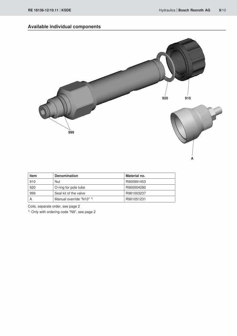
Available individual components
Item Denomination Material no.910 Nut R900991453920 O-ring for pole tube R900004280999 Seal kit of the valve R961003237A Manual override "N10" 1) R901051231
A
Coils, separate order, see page 21) Only with ordering code "N9", see page 2
920 910
999

Bosch Rexroth AG HydraulicsZum Eisengießer 197816 Lohr am Main, Germany Phone +49 (0) 93 52 / 18-0 Fax +49 (0) 93 52 / 18-23 [email protected] www.boschrexroth.de
© This document, as well as the data, specifications and other informa-tion set forth in it, are the exclusive property of Bosch Rexroth AG. It may not be reproduced or given to third parties without its consent. The data specified above only serve to describe the product. No state-ments concerning a certain condition or suitability for a certain applica-tion can be derived from our information. The information given does not release the user from the obligation of own judgment and verification. It must be remembered that our products are subject to a natural process of wear and aging.
KSDE RE 18136-12/10.1110/10 Bosch Rexroth AG Hydraulics
Notes
Bosch Rexroth AG HydraulicsZum Eisengießer 197816 Lohr am Main, Germany Phone +49 (0) 93 52 / 18-0 Fax +49 (0) 93 52 / 18-23 [email protected] www.boschrexroth.de
© This document, as well as the data, specifications and other informa-tion set forth in it, are the exclusive property of Bosch Rexroth AG. It may not be reproduced or given to third parties without its consent. The data specified above only serve to describe the product. No state-ments concerning a certain condition or suitability for a certain applica-tion can be derived from our information. The information given does not release the user from the obligation of own judgment and verification. It must be remembered that our products are subject to a natural process of wear and aging.
RE 18136-12/10.11 KSDE 11/10Hydraulics Bosch Rexroth AG
Notes

Bosch Rexroth AG HydraulicsZum Eisengießer 197816 Lohr am Main, Germany Phone +49 (0) 93 52 / 18-0 Fax +49 (0) 93 52 / 18-23 [email protected] www.boschrexroth.de
© This document, as well as the data, specifications and other informa-tion set forth in it, are the exclusive property of Bosch Rexroth AG. It may not be reproduced or given to third parties without its consent. The data specified above only serve to describe the product. No state-ments concerning a certain condition or suitability for a certain applica-tion can be derived from our information. The information given does not release the user from the obligation of own judgment and verification. It must be remembered that our products are subject to a natural process of wear and aging.
KSDE RE 18136-12/10.1112/10 Bosch Rexroth AG Hydraulics
Notes