Embed Size (px)
Citation preview

Whether or not the flow conditions correspond to the 'ponded water case' can be found from the piezometer readings.
21.9 Mole Drainage
Heavy soils of low hydraulic conductivity (less than 0.01 m/day) often require very closely spaced drainage systems (2-4 m spacings) for satisfactory water control. With conventional pipes, the cost of such systems is usually uneconomic and hence alternative techniques are required. Surface drainage is one possibility; the other is mole drainage.
Mole drains are unlined circular soil channels which function like pipe drains. Their major advantage is their low cost, and hence they can be installed economically at very close spacings. Their disadvantage is their restricted life, but, providing benefit- cost ratios are favourable, a short life can be acceptable.
The success of a mole drainage system is dependent upon satisfactory water entry into the mole channel and upon the mole channel itself remaining stable and open for an acceptable period. Currently, mole drainage systems are most commonly used for surface water control in perched watertable situations. These systems, as applied in the United Kingdom and in New Zealand, have been comprehensively reviewed by Nicholson (1942) for the U.K., and by Hudson, et al. (1962) and Bowler (1980) for New Zealand.
Mole drains are also used in some groundwater problem areas and in paddy fields (Soong and Wei 1985). Their use as a temporary subsurface drainage system for the reclamation of saline and saline sodic soils has been successful in field experiments (Sommerfeldt and Chang 1986; Spoor et al. 1990).
21.9.1 Mole Drain Formation
Mole drains are formed with a mole plough (Figure 21.51), which comprises a cylindrical foot attached to a narrow leg, followed by a slightly larger diameter cylindrical expander. The foot and expander form the drainage channel and the leg generates a slot with associated soil fissures which extend from the surface down into the channel. The leg fissures are vertical and are formed at an angle of approximately 45" to the direction of travel (Godwin et al. 1981). Mole plough dimensions, as commonly used in the United Kingdom and New Zealand, are given in Table 21.14.
Table 21.14 Common mole plough dimensions
Foot Expander h g Side length diameter diameter thickness of leg
("> (") (") ("1 United Kingdom 75 85 - 100 25 200 New Zealand 50 75 16 200
913
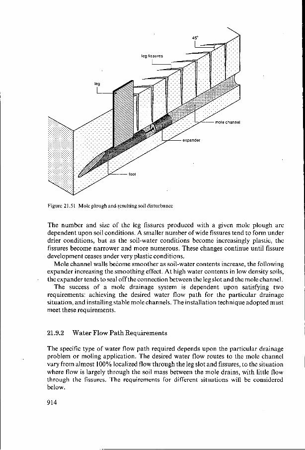
Figure 21 .S 1 Mole plough and resulting soil disturbance
The number and size of the leg fissures produced with a given mole plough are dependent upon soil conditions. A smaller number of wide fissures tend to form under drier conditions, but as the soil-water conditions become increasingly plastic, the fissures become narrower and more numerous. These changes continue until fissure development ceases under very plastic conditions.
Mole channel walls become smoother as soil-water contents increase, the following expander increasing the smoothing effect. At high water contents in low density soils, the expander tends to seal off the connection between the leg slot and the mole channel.
The success of a mole drainage system is dependent upon satisfying two requirements: achieving the desired water flow path for the particular drainage situation, and installing stable mole channels. The installation technique adopted must meet these requirements.
'
21.9.2 Water Flow Path Requirements
The specific type of water flow path required depends upon the particular drainage problem or moling application. The desired water flow routes to the mole channel vary from almost 100% localized flow through the leg slot and fissures, to the situation where flow is largely through the soil mass between the mole drains, with little flow through the fissures. The requirements for different situations will be considered below.
914
. . . . . . . . . . . . . . . . . . . watertable . . . . . . . . . . . . . . . . . .
. . . . . . . . . . . . . . . . . . . . . . . . . . . . . . . . . . . . . . . . . . . .
ponded water V
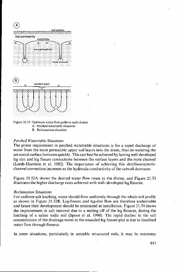
Figure 21.52 Optimum water flow paths to mole drains A: Perched watertable situation B: Reclamation situation
Perched Watertable Situations The prime requirement in perched watertable situations is for a rapid discharge of water from the more permeable upper soil layers into the drain, thus de-watering the saturated surface horizons quickly. This can best be achieved by having well-developed leg slot and leg fissure connections between the surface layers and the mole channel (Leeds-Harrison et al. 1982). The importance of achieving this slot/fissure/mole- channel connection increases as the hydraulic conductivity of the subsoil decreases.
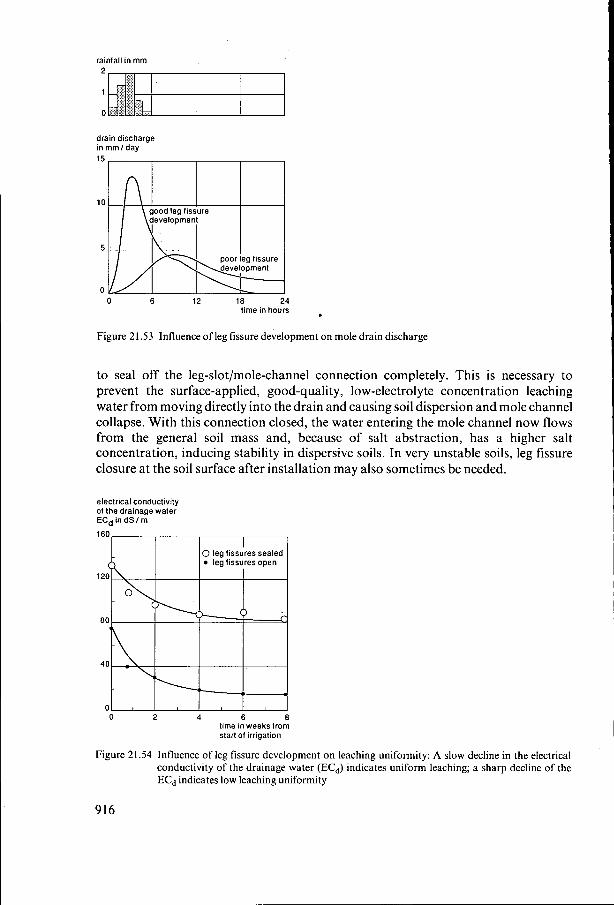
Figure 21.52A shows the desired water flow route to the drains, and Figure 21.53 illustrates the higher discharge rates achieved with well- developed leg fissures.
Reclamation Situations For uniform salt leaching, water should flow uniformly through the whole soil profile as shown in Figure 21.52B. Leg-fissure and leg-slot flow are therefore undesirable and hence their development should be minimized at installation. Figure 21.54 shows the improvement in salt removal due to a sealing off of the leg fissures, during the leaching of a saline sodic soil (Spoor et al. 1990). The rapid decline in the salt concentration of the drainage water in the unsealed leg fissure plot is due to localized water flow through fissures.
In some situations, particularly in unstable structured soils, it may be necessary
915
rainfall in mm 2
1
O
drain discharge in mm I day
O 6 12 18 24 time in hours ,
Figure 21.53 Influence of leg fissure development on mole drain discharge
to seal off the leg-slot/mole-channel connection completely. This is necessary to prevent the surface-applied, good-quality, low-electrolyte concentration leaching water from moving directly into the drain and causing soil dispersion and mole channel collapse. With this connection closed, the water entering the mole channel now flows from the general soil mass and, because of salt abstraction, has a higher salt concentration, inducing stability in dispersive soils. In very unstable soils, leg fissure closure at the soil surface after installation may also sometimes be needed.
electrical conductivity of the drainage water ECd in dS I m
O 2 4 6 8 time in weeks trom start of irrigation
Figure 21.54 Influence of leg fissure development on leaching uniformity: A slow decline in the electrical conductivity of the drainage water (ECd) indicates uniform leaching; a sharp decline of the ECd indicates low leaching uniformity
916
Flood Irrigation Situations A direct fissure/leg-slot connection between the soil surface and the mole channel in flood irrigation situations is highly undesirable, since it will result in the direct loss of irrigation water to the drain, and will increase the risk of high velocity water flow through the fissures and drains causing soil erosion. Throttled or sealed connections are therefore required in these situations.
Groundwater Control Situations In groundwater control situations, the presence or absence of leg fissures has little influence on the flow of water into the mole channel. The type of fissure development in the surface layers at installation is therefore not particularly critical.
Paddy Field Situations Drainage is only required in paddy fields at certain growth stages of the rice crop, the discharge from the mole drains being blocked at other times. The mole drains will function either with or without fissure development, although discharge rates will differ accordingly, in a similar manner to the situation illustrated in Figure 21.53. Providing there is good mole channel stability, good fissure/leg-slot/mole-channel connections are desirable to allow the rapid drawdown of water from the paddy above.
21.9.3 Achievement of Desired Water Flow Paths
The desired water flow path can be achieved by modifying, as necessary, the extent of leg fissure development and the effectiveness of the connection between the leg slot and the mole channel itself. Fissure development can be modified by moling under different moisture conditions as described in Section 21.9.1, or by adjusting the geometry of the mole plough leg (Spoor et al. 1989).
The number and size of the leg fissures generated in any given soil condition depends upon the sliding resistance between the soil and the side of the leg. The greater this resistance, the fewer the number but the wider and more well-developed the fissures become. Within limits, this resistance, and hence crack development, can be' increased by increasing leg thickness, leg roughness, or side area, and vice versa. Crack development is most sensitive to leg thickness and roughness when soil adhesion is low, and to side area when adhesion is high. It is also greater in soils with high air-filled porosities.
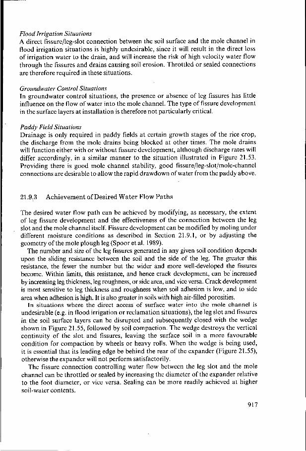
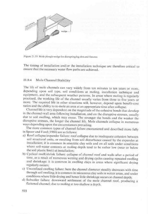
In situations where the direct access of surface water into the mole channel is undesirable (e.g. in flood irrigation or reclamation situations), the leg slot and fissures in the soil surface layers can be disrupted and subsequently closed with the wedge shown in Figure 21.55, followed by soil compaction. The wedge destroys the vertical continuity of the slot and fissures, leaving the surface soil in a more favourable condition for compaction by wheels or heavy rolls. When the wedge is being used, it is essential that its leading edge be behind the rear of the expander (Figure 21.55), otherwise the expander will not perform satisfactorily.
The fissure connection controlling water flow between the leg slot and the mole channel can be throttled or sealed by increasing the diameter of the expander relative to the foot diameter, or vice versa. Sealing can be more readily achieved at higher soil-water contents.
917
e) Slurry failure: here the channel rapidly fills with slurried soil; it is common in the less stable structured soils and in all soils where significant water inflow occurs soon after installation;
f) Infill failure: soil falling into the mole channel from the surface layers through open leg fissures and leg slot; it is common following surface cultivation during dry periods with open leg slots;
g) Erosion failure: soil eroded from channel floor and walls; it is most common in weakly structured soils and when large channel gradients induce high flow velocities.
Adjustments to the mole-foot and expander geometry and to the installation technique can assist, in certain situations, in maximizing channel resistance to collapse through specific failure mechanisms. Identifying the failure mechanisms most likely to be active allows the selection of the most appropriate equipment and installation techniques to maximize mole channel life. The soil, timing, equipment, and installation factors influencing mole channel stability and the requirements for extensive channel life will now be discussed.
21.9.5 Requirements for Long-Term Mole Channel Stability
' i
Numerous factors, detailed below, influence the success of a moling scheme, and the more closely the soil and installation conditions approach them, the more successful the operation is likely to be.
Clay Content Soil clay content is particularly important because of its influence on the magnitude of the cohesive forces which are necessary for channel stability. Some of the best moling soils have clay contents in excess of 45%, whereas soils with less than 30% clay are rarely good molers. Uniform soils are most satisfactory. Mole channels in soils containing sand or silt pockets are more prone to collapse.
Clay Mineralogy The major influence of clay mineralogy is on the nature of mole channel deterioration. Smectitic clays are more likely to collapse through expander and cyclical swell/shrink failures, and micaceous clays through unconfined swelling.
Structural Stability on Wetting Soil structural stability on wetting is a crucial factor influencing channel life. The more resistant the soil structural units are to collapse on wetting, the more stable the mole channels are likely to be (Rycroft and Alcock 1974). The Childs and Emerson Stability Tests (Childs 1942; Emerson 1967) are frequently used to assess soil structural stability for moling purposes. The Emerson Test, based on visual assessments of the slaking and dispersion properties of soils, is quick and useful for identifying very weakly structured soils. The Childs Test is more time-consuming but is appropriate for the complete range of soils. Structural stability is assessed on a basis of differences between the water-release characteristics of initially air-dry samples, wetted very rapidly by flooding, and slowly through capillarity.
919
Weakly structured and dispersive soils are unsuitable for moling, unless the electrolyte or salt concentration of the drainage water entering the mole channel can be increased to improve stability. This can be achieved in saline soils by preventing the direct access of surface water of low electrolyte concentration through the leg fissures and leg slot. The introduction of soil-amending materials such as gypsum into the neighbourhood of the channel also assists an increasing electrolyte concentration.
Soil Packing State Soil aggregate density itself cannot be changed during the moling operation because the aggregates at moling depth are usually saturated. There are some indications, however, that mole channels in soils with a high bulk density tend to be more stable than those in low density ones, because of slower swelling rates.
Timing of Moling Operation Significant water inflow into the mole channel soon after formation reduces channel life considerably and induces slurry failure. If the channel can age or mature for a number of weeks (2 to 3 minimum) before being wetted, it will be much more resistant to collapse. Moling during a drying period is therefore most desirable. An extended drying period after moling in smectitic clay soils may, however, cause excessive and undesirable shrinkage in the leg slot area, leading to considerable channel in-fill with surface soil. Where moling has to be done in the presence of a perched watertable or of free water at moling depth with immediate water entry, this moling should be regarded as a de-watering operation and the operation should be repeated later under drier conditions.
Soil at moling depth needs to be in a state of plastic consistency to enable the formation of the most stable, firm, smooth-walled mole channel. The smooth wall is preferably fissured at intervals along its length, the fissures acting as focal points for water entry.
Moling Depth Mole channels are commonly installed at depths between 0.4 and 0.7 m, although there is no restriction to deeper installation. Wherever possible, installation should always be in the most suitable and structurally stable soil layer. Moles should be installed deeper in situations where deep soil drying and cracking are likely to occur; this reduces the risks of cyclical swell/shrink failures.
For any mole-foot/expander combination, there is a critical minimum moling depth for stable channel formation. Working shallower than this critical depth loosens the soil and induces a rapid subsoiler failure. This loosening failure can be readily identified by excessive soil heave at the surface and through the absence of the leg fissures, angled at 45" to the direction of travel (see Figure 21.51). The herringbone pattern of leg fissures along the mole run is usually very obvious at the soil surface when the moles are being installed correctly, below the critical minimum depth. Reducing the diameters of the mole plough foot and expander brings the critical minimum moling depth closer to the surface, hence allowing shallower moling.
Mole Drain Spacing Because of the semi-permanent nature of mole drains and the risks of collapse, spacings
920
closer than those required to meet the drainage design criteria are usually adopted. This ensures that drainage performance is not seriously impaired if some of the mole drains collapse. These closer spacings have minimal implications on cost, because mole drains are very cheap to install. Common mole drain spacings range between 2.0 and 3.5 m.
Length of Mole Run The length of the mole run between outfalls is dependent upon the estimated chances of moling success. The greater the risk of channel failure, the shorter the length of run adopted, to minimize the effect of local collapse on overall drainage efficiency. Factors such as the moling qualities of the soil, surface irregularities and gradients, possible reverse gradients, and the presence of sand and silt pockets are usually considered when deciding upon run length. Common lengths of run vary from approximately 20 to 100 m. The length may have to be reduced on steep gradients to avoid channel erosion.
Mole Foot and Expander Diameter The most commonly used diameters for mole foot and expander were indicated in Table 21.14. The choice is dependent upon the most probable type of mole channel failure, soil conditions at installation, depth requirements, and the power available.
Where unconfined swelling failures are expected, larger diameter mole channels should be installed to extend their working life. Soils prone to roof collapse and expander failure, on the other hand, benefit from smaller diameter channels. Expander failure is very common following installation under marginally dry conditions (soil at or very close to its plastic limit). In these circumstances, the expander diameter should be only slightly larger than the foot diameter, its function being only to smooth out the channel walls rather than induce further deformation.
In situations where it is necessary to seal off the mole channel from the leg slot above, this can be achieved by increasing the expander diameter relative to the foot diameter. Conversely, in circumstances where a good open connection is required between leg slot and channel and the leg slot and fissures are only weakly formed, removing the expander completely will help keep the connection open. This latter situation is common when moling under softer, very plastic soil conditions.
In all cases when foot and expander diameters are being manipulated, care is required to ensure that the changes do not cause a subsoiler failure through installation above the critical minimum depth. When power is limited, smaller diameter channels are installed at shallower depths. ,
Mole Channel Outlets A good stable outfall for the mole channel is essential for successful moling. Outfalls
, into open ditches must be stabilized with short lengths of pipe (0.8 to 1.0 m long) at the outlet. Severe channel wall drying from an open ditch outfall during very dry periods can cause premature collapse, particularly in smectitic clay soils. Closing the outfalls at the beginning of a dry period will help to avoid this problem, otherwise a longer length of stabilizing pipe should be inserted into the channel to protect and support the most vulnerable section near the open ditch.
Very satisfactory, although more expensive, outfalls can be achieved by drawing
92 1
soil surface
‘collector or field drain
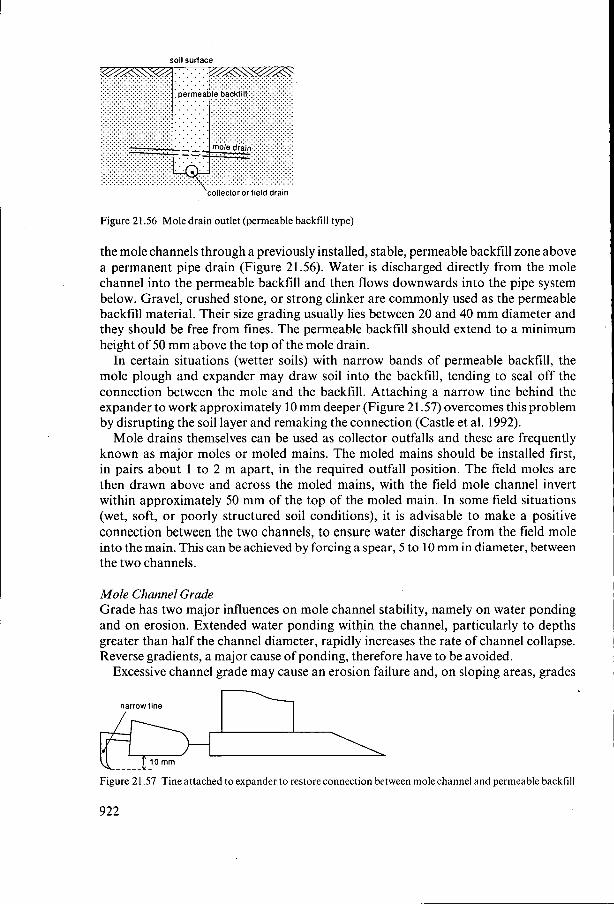
Figure 21.56 Mole drain outlet (permeable backfill type)
the mole channels through a previously installed, stable, permeable backfill zone above a permanent pipe drain (Figure 21.56). Water is discharged directly from the mole channel into the permeable backfill and then flows downwards into the pipe system below. Gravel, crushed stone, or strong clinker are commonly used as the permeable backfill material. Their size grading usually lies between 20 and 40 mm diameter and they should be free from fines. The permeable backfill should extend to a minimum height of 50 mm above the top of the mole drain.
In certain situations (wetter soils) with narrow bands of permeable backfill, the mole plough and expander may draw soil into the backfill, tending to seal off the connection between the mole and the backfill. Attaching a narrow tine behind the expander to work approximately 10 mm deeper (Figure 21.57) overcomes this problem by disrupting the soil layer and remaking the connection (Castle et al. 1992).
Mole drains themselves can be used as collector outfalls and these are frequently known as major moles or moled mains. The moled mains should be installed first, in pairs about 1 to 2 m apart, in the required outfall position. The field moles are then drawn above and across the moled mains, with the field mole channel invert within approximately 50 mm of the top of the moled main. In some field situations (wet, soft, or poorly structured soil conditions), it is advisable to make a positive connection between the two channels, to ensure water discharge from the field mole into the main. This can be achieved by forcing a spear, 5 to 10 mm in diameter, between the two channels.
Mole Channel Grade Grade has two major influences on mole channel stability, namely on water ponding and on erosion. Extended water ponding within the channel, particularly to depths greater than half the channel diameter, rapidly increases the rate of channel collapse. Reverse gradients, a major cause of ponding, therefore have to be avoided.
Excessive channel grade may cause an erosion failure and, on sloping areas, grades
narrow line
Figure 21.57 Tine attached to expander to restore connection between mole channel and permeable backfill
922
between 1 in 40 and 1 in 60 are often considered optimum. Lower grades are satisfactory, providing local reverse grades can be avoided.
The risk of local reverse grades developing increases as local variations in surface elevation increase. In certain situations, it may be advantageous to grade the mole channel positively, to a gradient different from that of the general soil surface.
Under certain conditions, with relatively large channel gradients and higher flow velocities, a local channel blockage can disrupt water flow, causing water to ‘blow-out’ to the surface, creating a wet area. This problem can be minimized by reducing channel gradients.
Grade Control at Installation The gradient of the installed mole channel is usually similar to the average gradient of the soil surface. No direct grade-control measures (e.g. the use of rotating lasers) are normally employed at installation. The channel gradient is controlled either by the mole plough itself, or through its hitching arrangement to the tractor. Critical requirements are to avoid reverse gradients and sudden changes in channel grade. Reverse gradients encourage water ponding, and sudden grade changes induce subsoiler failures in the channel; both cause rapid collapse.
The prime grading requirement during mole drain installation is that the mole foot should run at the required depth, parallel to the average grade of the soil surface. Local surface undulations should not cause the mole channel to deviate significantly from this average grade. The potential for achieving this is dependent upon the type of mole plough, its adjustment, and the site conditions.
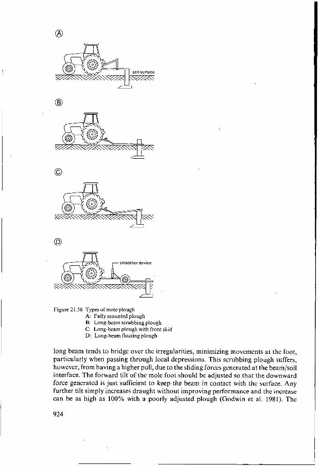
Four basic types of mole plough are available (Figure 21.58): A) Fully mounted: the plough is attached directly to the 3-point linkage of the tractor; B) Long-beam scrubbing mole plough: here a long beam (3 to 4 m long), carrying
the mole plough leg and foot, moves along in contact with the soil surface; C) Long-beam mole plough with front skids: the beam runs clear of the ground, but
it is supported on front skids; the depth is controlled by angling the leg and foot assembly relative to the beam;
D) Long-beam floating mole plough: the complete beam rides clear of the soil surface; this plough is usually attached to the tractor through a smoother device to reduce the effects of tractor pitching on mole foot movement.
The first three types of plough have been described in detail by Hudson et al. (1962) and the fourth by Spoor et al. (1987).
The best results with the mounted mole plough are achieved when it is used with the tractor linkage operating in ‘free float’, rather than in draught control mode. The depth of operation and hence channel gradient in draught control can vary greatly, even on smooth surfaces, because of changes in soil conditions. Mounted mole ploughs are only satisfactory on smooth field surfaces. Once local surface irregularities become significant, performance is poor. It is also essential to ensure that the tractor can generate adequate traction for the operation, without having to be operated in draught control.
The long-beam scrubbing and front-skid mole ploughs are more satisfactory than the mounted types when local surface undulations are more significant. The scrubbing
923
o
smoother device
Figure 21.58 Types of mole plough A: Fully mounted plough B: Long-beam scrubbing plough C Long-beam plough with front skid D: Long-beam floating plough
long beam tends to bridge over the irregularities, minimizing movements at the foot, particularly when passing through local depressions. This scrubbing plough suffers, however, from having a higher pull, due to the sliding forces generated at the beam/soil interface. The forward tilt of the mole foot should be adjusted so that the downward force generated is just sufficient to keep the beam in contact with the surface. Any further tilt simply increases draught without improving performance and the increase can be as high as 100% with a poorly adjusted plough (Godwin et al. 1981). The
924
. . . . . . . . '??% . . . . .K. . .4,5n!.: . :Y, F: . .
' , ' " " . . . . L~.'.'.'.'.',', . . . . . . . . . . . . . . . . . . . . . . . . .
. . . . . . . . . . . . . . . . . . . . . . . . . . . . . .
. . . . . . . . . . . . . . . . . . . . . . . . . . . . . . . . . . . . . . . . . . . . . . . . . . . . . . . . . . . . . . . . . . . . . . . . . . . . . . . . . . . . . . . . . . . . . . . . . . . . . . . . . . . . . . . . . . . . . . . . . . . . . . . . . . . . . . . . . . . . . . . . . . . . . . . . . . . . . . . . . . . . . . . . . . . . . . . . . . . . . . . . . . . . . . . . . . . . . . . . . . . . . . . . . . . . . . . . . . . . . . . . . . . . . . . . . . . . . . . . . . . .
@
. . . . . . . . . . . . . . . . . . . . . . . . . . . . . . . . . . . . . . . . . . . . . . . . . . . . . . . . . . . . . . . . . . . . . . . . . . . . . .
. . . . . . . . . . . . . . . . . . . . . . . . . . . . . . mole channel. . . . . . . . . . . . . . . . . . . . . . . . . . . . . .
. . . . . . . . . . . . . . . . . . . . . . . . . . . . . . . . . . . . . . . . . . . . . . . . . . . . . . . . . . . . . . . . . . . . . . . . . . . . . . . . . . . . . . . . . . . . . . . . . . . . . . . . . . . . . . . . . . . . . . . . . . . . . . . . . . . . . . . .
. . . . . . . . . . . . . . . . . . . . . . . . . . . . . . . . . . . . . . .
. . . . . . . . . . . . . . . . . . . . . . . . . . . . . . . . . . . . . . . . . . . . . . . . . . . . . . . . . . . . . . . . . . . . . . . . . . . . . . . . . . . . . . . . . . . . . . . . . . . . . . . . . . . . . . . . . . . . . . . . . .
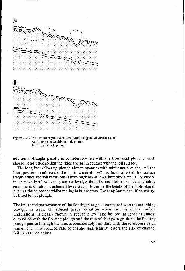
Figure 2 1.59 Mole channel grade variation (Note: exaggerated vertical scale) A: Long-beam scrubbing mole plough B: Floating mole plough
additional draught penalty is considerably less with the front skid plough, which should be adjusted so that the skids are just in contact with the soil surface.
The long-beam floating plough always operates with minimum draught, and the foot position, and hence the mole channel itself, is least affected by surface irregularities and soil variations. This plough also allows the mole channel to be graded independently of the average surface level, without the need for sophisticated grading equipment. Grading is achieved by raising or lowering the height of the mole plough hitch at the smoother whilst moling is in progress. Rotating lasers can, if necessary, be fitted to this plough.
The improved performance of the floating plough as compared with the scrubbing plough, in terms of reduced grade variation when moving across surface undulations, is clearly shown in Figure 21.59. The hollow influence is almost eliminated with the floating plough and the rate of change in grade as the floating plough passes through the rise, is considerably less than with the scrubbing beam implement. This reduced rate of change significantly lowers the risk of channel failure a t those points.
925
21.9.6 Gravel Moles
In situations where mole channels collapse quickly, through causes other than complete soil structural instability, their life can be increased considerably by in-filling them with stone or gravel (Mulqueen 1985). The installation equipment comprises a hollow leg approximately 75 mm wide, with a gravel hopper above. The gravel is inserted into the channel through the hollow leg, and the thickness of the gravel zone in the channel is controlled by an adjustable gate at the rear of the leg. The size range of gravel used is between 5 and 15 mm diameter, to ensure free flow without bridging during installation. The large side area of the leg produces leg fissures similar to conventional mole plough leg fissures. These fissures provide direct access for water from the surface layers into the gravel filled channel.
21.9.7 Mole Drainage Investigations
The performance of mole drainage systems, and the identification of changes in installation and equipment that may be advantageous for the future, can be determined by direct observation and through measurements of the discharge characteristics of the system.
Leg-fissure development, and the extent of any sealing of leg-slot/channel connections at the time of installation, can be most readily determined by excavating along one side of the leg slot and channel to expose the section shown in Figure 21.51. The extent of mole channel deterioration or failure with time can be determined by taking gypsum or plastic foam castes of the channel itself or by observation through an endoscope (Leeds-Harrison et al. 1983). The caste method is a destructive one, whereas regular observations can be made through the endoscope without causing any channel damage. The endoscope offers many advantages for identifying the nature of channel deterioration. For endoscope observation, an access tube is either inserted into the top of the mole channel at installation, or augered in later. A 10 mm diameter plastic pipe is commonly used for this purpose.
The efficiency of the mole drainage system can best be assessed on the basis of the shape of the discharge hydrograph (Figure 21.53; Leeds-Harrison et al. 1982). With a satisfactory mole channel, a peaked hydrograph indicates good leg-fissure development, and a flat one, poor development. Deterioration in the channel itself will reduce the peak of the hydrograph. The desired shape of hydrograph will depend on the type of mole system and the water flow path required.
.
21.9.8 Introducing Mole Drainage into New Areas
The successful introduction of mole drainage into new areas is unlikely to be achieved without careful consideration of the water flow regime required and the type of equipment and technique needed to achieve the desired flow regime and stable mole channels under the prevailing and subsequent soil-water and weather conditions. Endoscope observations and discharge characteristics enable the existing problems to be quickly identified and provide the necessary information for making
926
improvements to the installation method. Detailed information is provided in Spoor (1 994) on the possibilities and the development techniques required for extending mole drainage into new areas.
References
Abdel-Dayem, M.S. 1986. A comparative study on the use of PVC and PE in manufacturing corrugated drainage tubing. Ministry of Irrigation, Water Research Center, Drainage Research Institute, Technical Report 53. Giza, Egypt, 24 p.
Boers, T.M. and C.L. van Someren 1979. Design of gravel envelope for silty and fine sandy soils in Pakistan. In: J. Wesseling (ed.), Proceedings of the International Drainage Workshop. ILRI, Wageningen, pp.
Bons, A. and T. van Zeijts 1991. Jet flushing, a method for cleaning subsurface drainage systems. Govt.
Bowler, D.G. 1980. The drainage of wet soils. Publ. Hodder & Stoughton. Broughton, R.S. (ed.) 1984. Mardan SCARP subsurface drainage design analyses, Canadian Drainage
Team, MARDAN SCARP, WAPDA, Lahore, Pakistan, 224 p. Broughton, R.S., M.A. Makhlouf and J. Metzger 1990. Features of large diameter corrugated polyethylene
pipes manufactured at Aga, Egypt. Proceedings of Symposium on Land Drainage for Salinity Control in Arid and Semi-arid Regions, Vol. 3. Cairo, Egypt, pp. 142-151.
Broughton, R.S., B.W. Fuller and R.B. Bonnell 1992. Water conveyance capacity of corrugated plastic drain pipe with internal diameters between 38 and 75 mm. Proceedings of the 6th International Drainage Symposium. Nashville Tennessee, American Society of Agricultural Engineers (ASAE), St. Joseph, pp.
Calhoun, C . 1972. Development of design criteria and acceptance specifications for plastic filter cloths.
Carroll, R.G. 1983. Geotextile Filter Criteria. Transportation Research Record 916, pp. 46-53. Castle, D.A., G. Spoor, E.O. Onasanya and A.K. Ormandy 1992. Mole plough and soil factors influencing
the hydraulic connection between mole channels and the permeable backfill placed over pipe drains. Journal of Agricultural Engineering Research 51, pp. 217-235.
Cavelaars, J.C. 1966. Hydrological aspects of the application of plastic drain pipes and filter materials. Symposium on Hydrological and Technical Problems of Land Drainage, October 1965, Prague.
Cavelaars, J.C. 1967. Problems of water entry into plastic and other drain tubes. Agricultural Engineering Symposium at the National College of Agric. Engineering. Silsoe, 5/E/46, 13 p.
Cavelaars, J.C. 1979. Composing a drainage pipe line of sections of different diameters. Proceedings International Drainage Workshop at Wageningen. ILRI Publication 25, pp. 402-413.
Comité Français des Géotextiles et Géomembranes 1986. Recommendations pour I’emploi des géotextiles dans les systkmes de drainage et de la filtration. Boulogne-Billancourt.
Childs, E.C. 1942. Stability of clay soils. Soil Science 53, pp. 79-72 Chow, V.T. 1973. Open channel hydraulics, International edition. McGraw-Hill Book Co., Singapore,
Christopher, B.R. and R.D. Holtz 1985. Geotextile Engineering Manual. U.S. Federal Highway
Dieleman, P.J. and B.V. Trafford 1976. Drainage Testing. Irrigation and Drainage Paper 28, FAO, Rome. Dierickx, W. 1980. Electrolytic analogue study of the effect of openings and surrounds of various
permeability on the performance of field drainage pipes. Rijksstation voor Landbouwtechniek, Publication 77, Merelbeke.
Dierickx, W. 1993. Research and developments in selecting drainage materials, Irrigation and Drainage Systems, Vol. 6, No. 4, pp. 291-310
Dinc, G., G.E. Merva and E.H. Kidder 1971. Proceedings National Drainage Symposium, Chicago. ASAE, St. Joseph, pp. 11-14.
EI Atfy, H., O. Wahid El-Din, H. El-Gamaal and H.P. Ritzema 1990. Hydraulic performance of subsurface collector drains in Egypt. Symposium on Land Drainage for Salinity Control in Arid and Semi-arid Regions. Drainage Research Institute, Cairo, Vol. 3, pp. 393-404.
713-73 1.
Service for Land and Water Use, Information Paper 28, Utrecht.
288-296.
Technical report 5-72-7 USWES, Vicksburg.
pp. 89-150.
Administration, Report FHWA-TS-86/203.
927
EI Atfy, H.E., M.Q. Abdel-Alim and H.P. Ritzema 1991. A modified layout of the subsurface drainage system for rice areas in the Nile Delta, Egypt. Agricultural Water Management 19, pp. 289-302.
Emerson, W.W. 1967. A classification of soil aggregates based on their coherence in water. Australian Journal of Soil Science 5, pp. 47-58.
Engelund, F. 1953. On the laminar and turbulent flow ofgroundwater through homogeneous sands. Trans. Danish Academy ofTechn. Science, No. 3.
Framji, K.K., B.C. Garg and S.P. Kauthish (eds.) 1987. Design practices for covered drains in an agricultural land drainage system. International Commission on Irrigation and Drainage, New Delhi, 438 p.
Giroud, J.P. 1982. Filter criteria for geotextiles. In: Proceedings of the Second International Conference on Geotextiles. Vol. 1. LasVegas, pp. 103-108.
Godwin, R.J., G. Spoor, P.B. Leeds-Harrison 1981. An experimental investigation into the force mechanics and resulting soil disturbance of mole ploughs. Journal of Agricultural Engineering Research 26, pp. 477-479.
Heerten, G. 1983. Filtereigenschaften von Geotextilen für den Erd- and Wasserbau. Wasser un Boden,
Heidemij 1972. Onderzoek naar de wrijvingsweerstand in een geribbelde plastic buis. N.V.
Hudson, A.W., H.G. Hopewell, D.G. Bowler and M.W. Cross 1962. The drainage of farm lands. Bulletin
Huisman, L. 1969. Stromingsweerstanden in leidingen. Mededeling nr. 14, KIWA, Rijswijk. Irwin, R.H. 1982. Hydraulic roughness of corrugated plastic tubing. Proceedings Second International
Irwin, R.W. and C . Tsang 1972. Hydraulic roughness of corrugated plastic tubing. ASAE, St. Joseph,
Irwin, R.W. and J. Motcyka 1979. Friction factors for corrugated plastic drainage pipe. Journal of the
Johnson, H.P. 1971. Hydraulic roughness in drain tile. National Drainage Symposium. ASAE, St. Joseph,
Kirkham, D. 1951. The effect of circular perforations of flow into subsurface drain tubes. Part 11.
Kirkham, D. 1957. The ponded water case. In: J.N. Luthin (ed.), Drainage of agricultural lands. American
Leeds-Harrison, P.B., G. Spoor, R.J. Godwin 1982. Water flow to mole drains. Journal of Agricultural
Leeds-Harrison, P.B., R.K. Fry, C.J. Cronin and J.E. Gregory 1983. A technique for the non-destructive
Millar, P.J., K.W. Ho and H.R. Turnbull 1980. A study of filter fabrics for geotechnical applications in
Mulqueen, J. 1985. The development ofgravel moledrainage. Journal of Agricultural Engineering Research,
Nederlands Normalisatie-Instituut 1990. NEN 5168: Geotextielen-Bepaling van de karakteristieke
Nicholson, H.H. 1942. The principles of field drainage. Cambridge, University Press. Ogink, H.J.M. 1975. Investigations on the hydraulic characteristics of synthetic fabrics. Delft Hydraulics
ONeil, P.V. 1983. Advanced Engineering Mathematics. Wadsworth Publishing Co., Belmont, pp.
Rankilor, P.R. 1981. Membranes in ground engineering. Wiley. Rycroft, D.W. and M. Alcock 1974. The assessment of suitability of soils for moling. Technical Bulletin
Schober, W. and H. Teindl 1979. Filter criteria for geotextiles. In: Proceedings of the Seventh European
Schultz, B. 1990. Guidelines in the construction of horizontal subsurface drainage systems. International
Smedema, L.K. and D.W. Rycroft 1983. Land drainage: planning and design of agricultural drainage
Soil Conservation Service 1971. National Engineering Handbook 16. Drainage of Agricultural Land. U.S.
pp. 348-353.
Heidemaatschappij Beheer, Arnhem, 14 p.
No. 18, Massey College, Palmerston North.
Drainage Workshop, Washington, pp. 52-62.
pp. 290-291,295 p.
Irrigation and Drainage Division, Vol. 105, IRI. pp. 29-36.
pp. 15-19.
Experiments and results. Agricultural Engineering 32,5, pp. 2 10-224.
Society of Agronomy, Madison, pp. 139-180.
Engineering Research 27, pp. 81-91.
monitoring of subsurface drains. Journal of Agricultural Engineering Research, 28, pp. 479-484.
New Zealand. Ministry of Works and Development, Central Laboratories Report no. 2-8OjS.
3 2 , ~ ~ . 143-151.
poriegrootte in droge toestand. NNI, Delft.
Laboratory, Publication 146.
1049- 1052.
75/5. Field Drainage Experimental Unit, Cambridge.
Conference on Soil Mechnics and Foundation Engineering. Vol. 2. Brighton, pp. 121-129.
Commission on Irrigation and Drainage, New Delhi, 236 p.
systems. Batsford, London, 376 p.
Department of Agriculture, Washington.
928
Soil Conservation Service 1988. Standard on Subsurface Drains. USDA-SCS, Washington D.C., pp.
Sommerfeldt, J.G. and C. Chang 1986. Desalinization of an irrigated, mole-drained saline clay loam soil. Canadian Journal of Soil Science, 67, pp. 263-269.
Soong, Si-Fu and Zhang Wei 1985. Subsurface drainage in lowland rice fields in China. In Soil Physics and Rice, IRRI, Los Banos, pp. 351-366.
Spalding, R. 1970. Selection of materials for subsurface drains. RRL Report LR 346, Road Research Laboratory, Crowthome.
Spoor, G. 1994. Application of mole drainage in the solution of subsoil management problems. In: N.S. Jayawardene and B.A. Stewart (eds.), Innovative management of subsoils. Advances in Soil Science. Springer-Verlag. New York. In press.
Spoor, G. and R.A. Ford 1986. Mechanics of mole drainage channel deterioration. Journal of Soil Science,
Spoor.G., R.J. Godwin and S.M. Miller 1987. Mole plough grade control. Journal of Agricultural Engineering Research, 38, pp. 145- 166.
Spoor, G., M.J. Hann and A.S. Centeno 1989. Influence of mole plough leg and expander geometry on soil disturbance. Proceedings I I th Congress on Agricultural Engineering, CIGR, Dublin.
Spoor, G., C.J. Cronin and P.B. Leeds-Harrison 1990. Mole drain installation for leaching purposes. Proceedings of Symposium on Land Drainage for Salinity Control in Arid and Semi Arid Areas. Cairo, Section 3, pp. 47-54.
Stuyt, L.C.P.M. 1992. The water acceptance of wrapped subsurface drains. Ph.D. Thesis Agricultural University, Wageningen, 305 p.
Sweetland, D.B. 1977. The performance on non woven fabrics as drainage screens in subdrains. Master of Science Thesis, University of Strathclyde.
U.S. Bureau of Reclamation 1978. Drainage Manual. U.S. Govt. Printing Office, Washington, 286 p. Van der Sluys, L. and W. Dierickx 1990. Comparative study of different porometry determination methods
for geotextiles. Geotextile and Geomembrane 9, pp. 183-198. Van Zeijts, T.E.J. 1987. Quality control of subsurface drainage works in The Netherlands. In: Installation
of pipe drains. Govt. Service for Land and Water Use, Information Paper 21, Utrecht, pp. 23-32. Van Zeijts, T.E.J. 1992. Recommendations on the use ofenvelopes based on experience in The Netherlands.
In: Proceedings 5th International Drainage Workshop, Lahore, Volume 3, IWASRI, Lahore, 5238-97. Van Zeijts, T.E.J. and W.H. Naarding 1990. Possibilities and limitations of trenchless pipe drain installation
in irrigated areas. In: Installation of pipe drains. Govt. Service for Land and Water Use, Information Paper 21, Utrecht,pp. 10-22.
Van Zeijts, T.E.J. and G. Zijlstra 1990. Rodding, a simple method for checking mistakes in drain installation. In: Symposium on Land Drainage for Salinity Control in Arid and Semi-Arid Regions, Cairo, Volume 3, Drainage Research Institute, Cairo, pp. 84-93.
Vlotman, W.F., F.A. Zuberi and M. Alikhan 1990. Gravel envelope selection, design and installation. In: W.F. Vlotman (ed.), Drain envelope testing, design and research. Workshop Proceedings. IWASRl Publication IO, pp. 3-3 I .
Vlotman, W.F., Shafiq-ur-Rehman and M.N. Bhutta 1992. Drain envelope design and review. ASAE 1992 Winter Meeting, Paper 922649,25 p.
Wahid El-Din, O., S. Abdel Dayem and M.H. Amer 1990. Hydraulic characteristics of some drain pipes used in Egypt. Proceedings of Symposium on Land Drainage for Salinity Control in Arid and Semi-arid Regions, Vol. 2. Cairo, pp. 225-236.
Wesseling, J. and F. Homma 1967. Hydraulic resistance of drain pipes. Netherlands Journal of Agricultural Sciences, 15, pp. 183-197.
Widmoser, P. 1966. Potentialströmungen zu geschitzten Rohren. Schweizerische Bauzeitung 84, no. 52. Willardson, L.S. 1974. Envelope materials. In: J. van Schilfgaarde (ed.), Drainage for Agriculture.
Agronomy 17. American Society of Agronomy, Madison, pp. 179-202. Winger, R.J. and W.F. Ryan 1970. Gravel envelopes for pipe drains design. Trans. ASAE 14(3). American
Society of Agricultural Engineers, St. Joseph, pp. 47 1-479. Zeigler, E.R., R.J. Winger and L.S. Willardson 1977. Friction, grade and alignment studies for corrugated
plastic drain tubing. Proceedings Irrigation and Drainage Specialty Conference. Water Management for Irrigation and Drainage, ASCE, Reno, pp. 146-161.
60611-60617.
38, pp. 369-382.
929