Embed Size (px)
Citation preview

103
All exposed concrete surfaces and adjoining work stained by spilling or
leakage of concrete shall be cleaned to the satisfaction of the Construction
Officer.
All cracks that appear in the concrete prior to acceptance of the work shall be
“veed” and filled with sealant.
2.1.5.8 EVALUATION AND ACCEPTANCE
After the removal of the forms any concrete, judged by the Construction
Officer as defective and beyond repair, shall be rejected, demolished and
replaced with new concrete in a manner acceptable to the CO. The
evaluation and acceptance of concrete shall be in accordance with Chapter
17 of ACI Standard 301.
2.1.5.9 INSPECTION
Installation of reinforcing steel, pipes, sleeves, anchors and other embedded
items, batching, mixing, transportation, placing, curing and finishing of
concrete shall at all times be subject to the inspection of the Construction
Officer.
No concrete shall be placed without prior notice to and approval of the
Construction Officer.
2.1.5.10 FIELD CONTROL
Sets of four (4) field control cylinder specimens will be taken at random by
the Construction Officer, in conformity with ASTM C31. Generally,
approximately one (1) per 50 cubic meters, but not less than one (1) set per
day will be made during concreting operations.
Two (2) cylinders will be tested after 7 days and two cylinders after 28 days.
Compressive tests, in accordance with the Standard test described in ASTM
Method C39, will be performed by a laboratory acceptable to the owner, and
paid directly by the Contractor.
The Contractor shall provide the concrete for the test cylinders and such
auxiliary personnel and equipment needed to take the test specimens.
2.1.5.11 FIELD TESTING
Should the average strength of the 28-day test specimens be less than that
specified in Table A, the Construction Officer may require drilled core
samples from the portion of the structure which was determined by him to
represent the deficient 28-day test specimens.
If the strength of any of the drilled core samples is less than the minimum
requirements shown in Table A, the Construction Officer may direct the
Contractor to strengthen or replace the portions of the structure concerned at
the Contractor’s expense, and the Construction Officer’s satisfaction
Drilled core samples shall be taken and tested in accordance with ASTM C42
except that they shall have an L/D ratio of not less than 1.25 prior to capping
for testing. All core samples so tested shall be tested in a saturated state.
All costs associated with the cutting and preparing of drilled core samples
shall be done by the Contractor. Testing of the drilled core samples shall be
at the expense of the Contractor.

104
Slump tests, entrained air measurements, temperature, and testing of
admixtures will be made in the field by the contractor at his own expense in
the presence of the Construction Officer.
2.2 CONCRETE REINFORCEMENT
2.2.1 GENERAL
2.2.1.1 SCOPE OF WORK
The Contractor shall furnish, fabricate and install all steel bar and tie wire,
clips, supports, chairs and spaces required for the reinforcement of concrete,
as shown on the Drawings and/or specified herein.
2.2.1.2 STANDARD SPECIFICATION REFERENCE
The following Standards are referred to:
ASTM A82 Cold Drawn Steel Wire for Concrete Reinforcement
ASTM A497 Welded Deformed Steel Wire Fabric for Concrete
Reinforcement
ASTM A615 Deformed Billet Steel Bars for Concrete Reinforcement
ASTM 315 Manual of Standard Practice for Detailing Reinforced
Concrete Structures
2.2.1.3 SHOP DRAWINGS
The Contractor shall submit three (3) sets of completely detailed working
drawings and schedules of all reinforcement for review to the CO. The
bending diagrams and bar lists shall be detailed in accordance with ACI 315.
Fabrication of reinforcement steel shall not proceed until the construction
joint locations and the shop drawings have been reviewed by the CO and
returned to Contractor marked “No comment”.
2.2.1.4 SUBSTITUTIONS
The following reinforcing steel bar sizes shall be used for all reinforced
concrete design under this Contract:
Bar Designation Approximate Cross
Section Area (mm2)
Approximate Unit
Weight (kg/m)
#10
#12
#16
#25
#28
#32
#36
78
113
201
492
615
804
1018
0.616
0.888
1.579
3.854
4.833
6.313
7.991

105
Should the Contractor wish to use reinforcing steel bars having areas
different from those shown (with consequent different designations), the
following requirements shall apply.
If the proposed substitute bar has an area from 97% to 105% of the
designated bar, a direct substitution may be made without changes to bar
spacing.
If the proposed substitute bar has an area less than 97% of the designated bar,
the substitution may be unacceptable without changes in bar spacing. If the
proposed substitute bar has an area more than 105% of the designated bar,
changes in spacing may be proposed by the Contractor. Changes in spacing
are limited to a maximum spacing of 300mm. All proposed changes shall be
submitted to the CO for approval.
Proposed changes spacing shall be submitted to the CO for
consideration by way of the reinforcing arrangement drawings
required as shop drawings. These should not be prepared until the
CO’s sanction in principle to the substitution has been obtained and
the CO’s guidelines received on such related criteria as maximum
and minimum spacing and bond requirements.
Approval by the CO of bar size substitution does not relieve the
Contractor from other specified requirements including steel grade
and bar deformations.
2.2.2 PRODUCTS
2.2.2.1 MATERIALS
Reinforcement steel shall be deformed, new billet steel bars conforming to
ASTM A615, grade 40 substantially free from mill scale, rust, grease or other
foreign matter.
Rail-steel bars will not be permitted in the work.
Reinforcement steel shall bear a mill identification symbol, and shall be
tagged with the size and mark number so that different types may be
identified and shall be stored off the ground to protect the steel moisture and
dirt, until placed in final position.
Steel wire for tying reinforcing and waterstops shall conform to ASTM A82.
Welded wire fabric for concrete reinforcement shall conform to ASTM A497.
Welded intersections shall be spaced no further apart than 40cm in the
direction of the principal reinforcement.
2.2.3 EXECUTION
2.2.3.1 FABRICATION OF REINFORCEMENT
Reinforcement steel shall be accurately formed to the dimensions shown on
the shop drawings and bar schedules.
All reinforcing bars shall be bent cold around a pin with a free revolving
collar having a diameter proportional to the diameter of the bar of not less
than the following:

106
a. Two times for stirrups.
b. Six times for bars up to and including 25mm diameter.
c. Eight times for bars over 25mm diameter.
Reinforcement steel shall not be straightened nor rebent. Bars with kinks or
bends not shown on the Drawings will not be accepted.
2.2.3.2 INSTALLATION OF REINFORCEMENT
Reinforcing bars shall be accurately placed as shown on the Drawings and in
accordance with the shop drawings and schedules. The reinforcing bars shall
be secured against displacement with annealed iron wire ties of minimum
1.5mm diameter or suitable clips at the intersections.
Except as otherwise indicated on the Drawings, reinforcement steel shall be
installed with a clearance for concrete cover follows:
a. Concrete placed directly on earth 75mm
b. Formed surfaces in contact with the
soil, water or exposed to the water 50mm
c. Concrete cover of main reinforcement
steel for columns and beams 50mm
d. Walls not in contact with the soil,
water or exposed to the weather 40mm
e. Underside of slabs over water surfaces
but not in contact with the water 50mm
f. All other slab surfaces 25mm
No reinforcing bars shall be welded.
All reinforcing bars in slabs shall be supported on concrete cubes or chairs of
the correct height, containing soft steel wires embedded therein for fastening
to the reinforcement steel. Such spacers or chairs shall have a minimum
compressive strength of 21 MPa.
Reinforcing bars for vertical surfaces in beams, columns and walls shall be
properly and firmly positioned from the forms by means of stainless steel
(tipped) boisters or other equal methods approved by the CO.
Reinforcement steel projecting from structures that are to be concreted or
where concrete has already been poured shall not be bent out of its correct
position.
Lapping of reinforcing bars shall be as indicated on the Drawings.
Before being placed in position, reinforcing bars shall be thoroughly cleaned
of rust, scale, dirt and other coating. When there is delay in placing of
concrete after reinforcing bars are in place, bars shall be re-inspected and
cleaned when necessary.

107
4.0 STRUCTURAL STEEL WORKS
4.1 DESCRIPTION
The work includes the furnishing of all labor, materials, equipment and transportation
required to complete fabrication, delivery and erection of all structural steel indicated in the
drawings and herein specified.
4.2 REFERENCE
The following publications of the issues listed below, but referred to thereafter by basic
designation only, form part of this specification to the extent indicated by the reference
thereto:
American Institute of Steel Construction (AISC) Publications:
Code of Standard Practice for Steel Buildings and Bridges, dated September 1,
1976.
Manual of Steel Construction - 7th Edition, including Supplements 1,2 and 3.
American National Standards Institute (ANSI) Publications:
B27.2 Plain Washers
American Society for Testing and Materials (ASTM) Publications:
A27 or A148 Cast Steel
A36 Structural Steel
A53 Steel Pipe
A12-73 Zinc (Hot-Galvanized) Coating on Products Fabricated from Rolled,
Pressed and Forged Steel Shapes, Plates, NBA’s and Strips.
A153-73 Zinc-Coating (Hot Dip) on iron and Steel Hardware.
A307-76B Carbon Steel Externally & Internally Threaded Standard Fasteners.
A325-76C High Strength Bolts for Structural Steel Joints, including suitable
Nuts and Plain Hardened Washers.
A550-77 Cold-Formed Welded and Seamless Carbon Structural Tubing in Rounds
and Shapes.
American Welding Society (AWS) Publications:
A5.1 Welding Electrodes
C1.1-75 Structural Welding Code

108
4.3 REQUIREMENT
In conformance with the General Conditions, the Contractor is required to furnish a
certificate from the manufacturer or producer, certifying that all materials or products
delivered to the job site meet the measurements specified herein.
4.4 SHOP DRAWINGS
The Contractor shall submit shop drawings to the Construction Engineer for approval in
accordance with the General Conditions. Shop Drawings shall consist of all shop and
erection details. All members and connection for any portion of the structure shown or not
shown on the contract drawings shall be detailed by the fabrication and indicated on the
shop symbols in accordance with the American Welding Society (AWS) Structural Welding
Code.
4.5 MATERIALS
Materials shall conform to the respective publications and other requirements specified
herein and as shown, and shall be the approved products of manufacturers regularly engaged
in the manufacture of such products.
Structural Steel shall conform to ASTM A36.
Structural Tubing shall conform to ASTM A500 or A501.
Steel Pipe shall conform to ASTM A53, Grade b.
Cast Steel, except as specified otherwise, and shall conform to ASTM A27 or A148,
as applicable. Castings to be welded shall be of composition suitable for welding
under field conditions.
High Strength Bolts, including Nuts and Washers, shall conform to ASTM A325.
Plain Washers, other those in contact with high strength bolt heads and nuts shall
conform to ASNI Standard B27.2, Type B.
Welding Electrodes and Rods shall conform to AWS A5.1, E60XX series.
Zinc Coating for threaded products shall conform to ASTM A153 and ASTM A123
for structural shapes.
Materials shall be delivered, stored, handled and installed in a manner to protect them from
all damage curing the entire construction period. Storage conditions shall be approved by
the Construction Officer in accordance with the General Conditions.
4.6 FABRICATION
4.6.1 GENERAL
Structural Steelworks material shall be in accordance with the applicable provisions
of these specifications. Fabrications and assembly shall be done in the shop to the
greater extent possible. Structural siteworks, except surfaces of steel to be encased
in concrete and surfaces of friction-type high-strength bottled connections, shall be
prepared for painting in accordance with the section entitled PAINTING and primed
with paint material specified. All materials shall be cleaned and straight. If
109
straightening is necessary, it shall be done by a process and in a manner that will not
damage the material.
Shearing, Flame cutting, and Chipping, shall be done carefully and accurately.
Flame-cut edges of members shall have all knicks removed. The top and bottom
surfaces of base plates, cap plates of columns and pedestals, sole plates, and
masonry plates shall be planned, or be hot straightened, and parts of members in
contact with them shall be faced. Sole plates of beams and girders shall have full
contact with the flanges. Compression joints, depending upon contact bearing, shall
have bearing surfaces machined to a common plane after the members are
completed. Bolts shall not be made or enlarged by burning. Members that cannot be
fitted up properly by cutting with a saw or by reaming holes to a maximum holes
elongation of 3mm larger than the nominal diameter will be rejected unless other
correction is approved by the Construction Officer. Gas cutting (Flame cutting) shall
be done by the use of mechanically guided torch. The use of a gas torch in the field
will not be permitted on any major member in the structural framing under stress,
and shall be subject to the approval of the Construction Officer. The radius of re-
entrant flame cut fillets shall not be less than 13mm, and all burned edges shall be
finished by grinding.
4.6.2 WELDED CONSTRUCTION
Welding on structural steelworks and tubular structures shall be done in accordance
with the applicable standards for welding of AWS Code D1.1.
4.6.2.1 QUALIFICATION OF WELDERS
Welding work shall only be performed by certified welders qualified in
accordance with the requirements of the AWS D1.1.
4.6.2.2 PROCEDURES
Welding procedures, type of electrodes, and type of equipment required for
the work shall be in accordance with the applicable provisions of AWS
D1.1. Type of electrodes to be used shall be compatible with the metal to be
welded.
4.6.3 BOLTED CONSTRUCTION
Holes for bolts shall be 1.5mm larger than the nominal diameter of bolt. Holes shall
be clean cut, without torn or rugged edges. Outside burrs resulting from reaming or
drilling shall be removed. Bolt holes shall be at right angles to the member. The
slope of bolted parts in contact with the bolt head shall not exceed 1:20 with respect
to a plane normal to the bolt axis. Where the surface of a bolted part has a slope of
more than 1:20, a beveled washer shall be used to compensate for lack of
parallelism.
4.6.3.1 COMMON BOLTS
Bolts transmitting shear shall be threaded to which a length that is not more
than one thread will be within the grip of the metal and the bolt shall be of
such length that they will extend entirely through the nuts, with the beveled
end outside of the nut. Bolt heads and nuts shall be drawn tight against the
work with a suitable wrench. Bolt threads shall be tapped with a hammer
while the nut being tightened.
4.6.3.2 HIGH-STRENGTH STEEL BOLTS

110
The allowable working stresses for high-strength steel bolts shall be as
given in ASTM A325. Bolted parts shall not be solidly together when
assembled and shall not be separated by gaskets or any other interposed
compressible materials. When assembled, all joints surfaces, including those
adjacent to the bolts heads, nuts, or washers, shall be free of scale, except
tight mill scale, and shall also be free of burrs, dirt, and other foreign
material that would prevent seating of the parts. Contact surfaces within the
friction type of joints shall be free fasteners in the joint are tight, at least the
minimum bolt tension shown in ASTM A325, for the size of fastener used.
Threaded bolts shall be tightened with properly calibrated wrenches or by
the “turn-of-the nut” method. Any bolt tightened by the calibrated wrench
method (or by torque control) shall have a hardened washer under the
element (nut or bolt head) turned tightening.
4.6.3.3 MATCH MARKING
Members and component parts of structures shall be assembled and matched
marked prior to insure accurate assembly and adjustment of position on
final erection. Painted assembly markings shall be removed from many
surfaces to be welded or bolted. Scratch or notch marks shall be located in a
manner that will not affect the strength of the members or cause
concentrations of stress.
4.6.3.4 SHOP PAINTING
Except as otherwise specified, all structural steelworks, except zinc-coated
surfaces and steelworks to be embedded in concrete or mortar, shall be shop
primed in accordance with the section entitled PAINTING.
4.7 ERECTION
4.7.1 GENERAL
Except as modified herein, erection shall be in accordance with the applicable
specifications and standards of the AISC Manual of Steel Construction. Erecting
equipment shall be suitable for the work and shall be in first class condition. Safety
belts and lines shall be used by workmen aloft on high structures, unless safe
working platforms or safety nets are provided.
4.7.2 ANCHORAGE
Anchor bolts and other connections between the structural steel and foundations
shall be provided and shall be properly located and built into the connecting work.
4.8 BASE AND BEARING PLATES
Base plates for columns and bearing plates for beams, girders and similar members shall be
provided with full bearing after the supported members have been plumbed and properly
positioned. The area under any plate bearing on concrete or masonry shall be dry-packed
solidly with grout.
4.9 ASSEMBLY
All members shall be adjusted to the well planned or bolted and rigidly made together
during final bolting or welding. Drifting done during assembling shall not distort the metal
or enlarge the holes. The member shall be free from twists, bends and other deformation.

111
The frame of steel structures shall be carried up true and plumb as shown and shown and all
match markings shall be followed.
Temporary bracing shall be used whenever necessary to support all loads to which all the
structure may be subjected and shall be left placed as long may be required for safety. The
various members forming parts of a completed frame or structure after being assembled
shall be aligned and adjusted accurately before being fastened. Fastening of splices of
compression members shall be done after the abutting surfaces have been brought
completely into contact. No welding or bolting shall be done until as much of the structure
as will be stiffened hereby has been aligned properly. Bearing surfaces and surfaces which
will be in permanent contact shall be cleaned before the members are assembled. Bearing
plates shall be set in exact position and shall have a full and even bearing upon the masonry.
As erection progresses, the work shall be bolted or welded sufficiently to take care of all
dead load, wind and erection stresses. Splices will be permitted only where indicated.
Erection bolts used in welded construction may be tightened securely and left in place,
unless otherwise indicated.
Field Bolting shall be in accordance with the requirements specified for the shop fabrication.
Unfair holes shall be corrected by reaming.
Field welding shall be as specified for shop fabrication of welded construction. Any shop
paint on surface adjacent to joints to be field welded shall be wire brushed to reduce the
paint film to a minimum.
4.10 FIELD REPAIR OF ZINC COATING
All zinc-coating that has been damaged in handling, transporting, welding or bolting shall be
repaired in accordance with the COATING section entitled PAINTING.
4.11 FIELD PRIMING
After erection, the field bolt heads and nuts, field welds, and any abrasions in the shop coat
shall be cleaned and primed in accordance with the section called PAINTING.
4.12 PAINTING
The type of paint, the number of coats, and the extent of the painting shall be in
conformance with the section entitled PAINTING. In general, all exposed surfaces of steel
work shall be painted. Surfaces where the shop coat has been damaged shall be retouched
using the same system as the original shop painting. Surfaces which will be contact after
erection, except when in contact in welded or bolted connections, shall be given one finish
coat or welds and the areas adjacent thereto shall be done promptly after the acceptance of
the weld and shall be as specified under shop painting.
4.13 INSPECTION
Inspection shall be made promptly to permit immediate correction of defects. The inspector
will mark each piece which is accepted, with the mark assigned to him. Unrestricted
inspection shall be conducted in both shop and field, to verify preparation, size, gauging,
location, acceptability of welds, identification marking and operation and current
characteristics or welding sets in use. The procedure for calibration of wrenches and
installation of bolts shall be subject to the approval of the Construction Officer. The
inspection and testing of welds shall be performed by the Contractor as deemed necessary by
the Construction Officer all at the expense of the Contractor, and shall be in accordance with
the applicable provisions of AWS Code D1.1.
112
4.14 FINAL CLEAN UP
Upon completion of erection and before final acceptance, the erector shall remove from the
jobsite all false-works, rubbish, and temporary structures furnished by him.

113
5.0 MOISTURE AND THERMAL PROTECTION
5.1 ROOFING
5.1.1 DESCRIPTION
The work includes installation of pre-painted Rib-type Long-span roofing complete
with hardware and accessories.
5.1.2 GENERAL
The work includes furnishing all materials and requirements performing all
operations to provide a long span corrugated twin ribbed roofing and miscellaneous
roofing works as required to provide an acceptable installation. Surfaces to which
metal formed roofing sheets are to be applied shall be thoroughly cleaned and
prepared, free from any defects that may affect the application. Metal formed
roofing shall be locked and lapped and installed as applicable. Specific installation
details shall be in accordance with manufacturer’s recommended installation
practice.
Metal formed roofing and sheets and accessories shall be carefully handled at all
times in strong and handling to prevent damage to the surfaces, edges and ends and
shall be slightly elevated for drainage.
Metal formed roofing and sheets and accessories shall be delivered to the site in the
original
sealed container or packages bearing the manufacturer’s name and brand designated
where materials are covered by a reference specification number, type and class as
applicable.
5.1.3 INSTALLATION
Lay and install the first sheet with the turned down edge towards the outside of the
area to be covered. Overlap the next sheet to the previous sheet in such a manner
that the exposed edge is turned down and the covered edge is turned up. Side up
fasteners should be done by rivets and washers spaced from 300 mm to 450 mm on
centers.
Care should be exercised in the proper anchorage of all roof frames.
Ridge strips for ridge rolls and ridge flashings are attached to the roofing sheets by
means of rivets. Other flashings are to be fabricated from plain sheets of the same
materials as the roofing in accordance with details and/or site requirements. These
are also attached to roofing sheets by means of rivet.
5.1.4 TEMPORARY PROTECTION
Metal formed roofing sheet surfaces requiring protection from stains, discoloration,
surface abrasion and other construction abuses shall be suitably protected in
accordance with the manufacturer’s recommendations.
114
5.1.5 FINAL CLEARING
Upon completion, the Contractor shall clean the metal formed roofing sheets
surfaces and drain line of burrs, leaves, stones and other foreign matter that may
impair the flow of water. Surface shall be kept clean by periodic inspection.
5.2 RADIANT HEAT BARRIER
5.2.1 SCOPE OF WORK
The Contractor shall furnish and install all labor and material to complete the
work.
5.2.2 MATERIAL
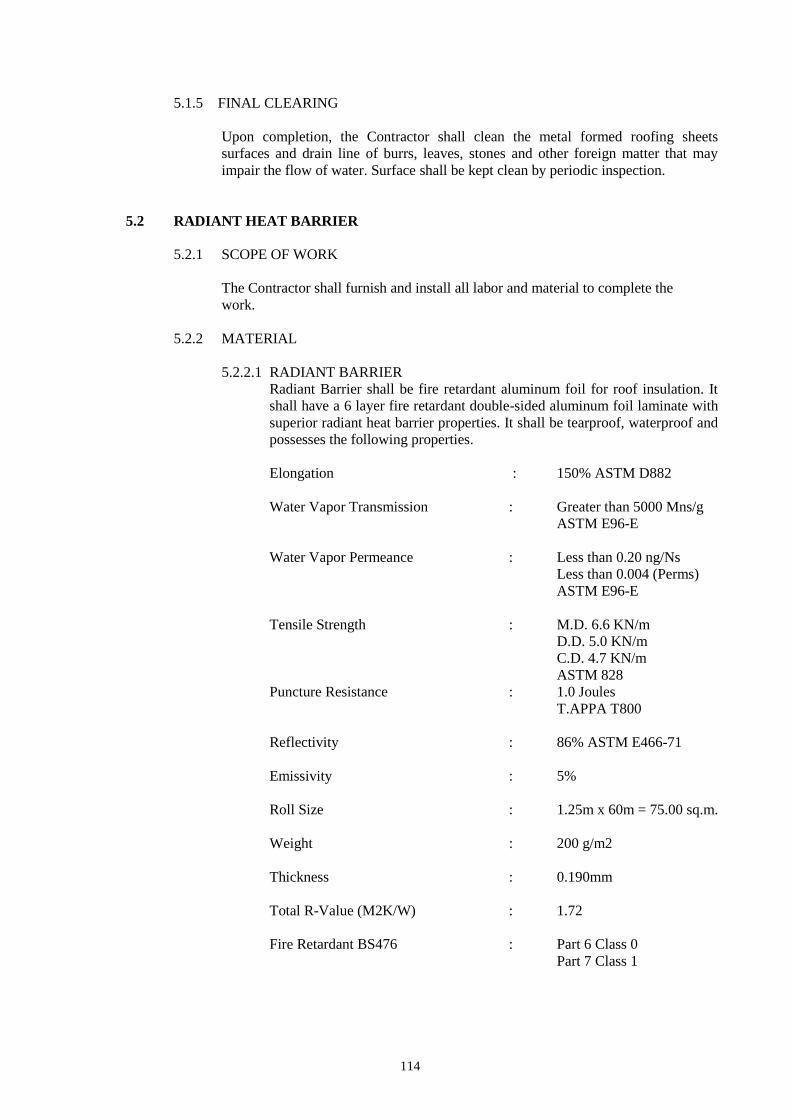
5.2.2.1 RADIANT BARRIER
Radiant Barrier shall be fire retardant aluminum foil for roof insulation. It
shall have a 6 layer fire retardant double-sided aluminum foil laminate with
superior radiant heat barrier properties. It shall be tearproof, waterproof and
possesses the following properties.
Elongation : 150% ASTM D882
Water Vapor Transmission : Greater than 5000 Mns/g
ASTM E96-E
Water Vapor Permeance : Less than 0.20 ng/Ns
Less than 0.004 (Perms)
ASTM E96-E
Tensile Strength : M.D. 6.6 KN/m
D.D. 5.0 KN/m
C.D. 4.7 KN/m
ASTM 828
Puncture Resistance : 1.0 Joules
T.APPA T800
Reflectivity : 86% ASTM E466-71
Emissivity : 5%
Roll Size : 1.25m x 60m = 75.00 sq.m.
Weight : 200 g/m2
Thickness : 0.190mm
Total R-Value (M2K/W) : 1.72
Fire Retardant BS476 : Part 6 Class 0
Part 7 Class 1

115
5.2.3 WORKMANSHIP
The product shall be delivered to the site in its original package or container bearing
the manufacturers name and brand designation.
All materials shall be installed by skilled and selected workmen familiar with the
aforementioned product.
5.2.4 INSTALLATION
The installation shall have a joint overlap of 75mm. It shall be unrolled foil down
length of roof from ridge.
For further information, see manufacturer’s specifications.
5.3 ELASTOMERIC WATERPROOFING MEMBRANE
5.3.1 SCOPE OF WORK
The Contractor shall furnish and install all materials and labor required to provide
waterproofing on designated locations.
5.3.2 MATERIAL
Elastomeric waterproofing membrane shall be liquid applied single component and
made by a reputable manufacturer.
5.3.3 PREPARATION
All surfaces to be waterproofed should be clean, sound and dry. Concrete surfaces
should have a light steel-trowel followed by a fine hair-broom or equivalent finish
that is dry and free from dust, oil and other contaminants. Remove all high spots.
Moss and lichen must be removed physically followed by treatment with fungal
wash down through and allow to dry. Lattence should be removed from concrete by
grit blasting, wire brushing or water jet blasting and allowing to dry.
For installation procedure and other information, see manufacturer’s specification.
116
ITEM 100 – CLEARING AND GRUBBING
100.1 Description
This item shall consist of clearing, grubbing, removing and disposing all vegetation
and debris as designated in the Contract, except those objects that are designated to
remain in place or are to be removed in consonance with other provisions of this
Specification. The work shall also include the preservation from injury or
defacement of all objects designated to remain.
100.2 Construction Requirements
100.2.1 General
The Engineer will establish the limits of work and designate all trees, shrubs,
plants and other things to remain. The Contractor shall preserve all objects
designated to remain. Paint required for cut or scarred surface of trees or
shrubs selected for retention shall be an approved asphalt base paint prepared
especially for tree surgery.
Clearing shall extend one (1) meter beyond the toe of the fill slopes or
beyond rounding of cut slopes as the case maybe for the entire length of the
project unless otherwise shown on the plans or as directed by the Engineer
and provided it is within the right of way limits of the project, with the
exception of trees under the jurisdiction of the Forest Management Bureau
(FMB).
100.2.2 Clearing and Grubbing
All surface objects and all trees, stumps, roots and other protruding
obstructions, not designated to remain, shall be cleared and/or grubbed,
including mowing as required, except as provided below:
(1) Removal of undisturbed stumps and roots and nonperishable solid
objects with a minimum depth of one (1) meter below subgrade or
slope of embankment will not be required.
(2) In areas outside of the grading limits of cut and embankment
areas, stumps and nonperishable solid objects shall be cut off not
more than 150 mm (6 inches) above the ground line or low water
level.
(3) In areas to be rounded at the top of cut slopes, stumps shall be cut
off flush with or below the surface of the final slope line.
(4) Grubbing of pits, channel changes and ditches will be required
only to the depth necessitated by the proposed excavation within such
areas.
(5) In areas covered by cogon/talahib, wild grass and other
vegetations, top soil shall be cut to a maximum depth of 150 mm
below the original ground surface or as designated by the Engineer,

117
and disposed outside the clearing and grubbing limits as indicated in
the typical roadway section.
Except in areas to be excavated, stump holes and other holes from which
obstructions are removed shall be backfilled with suitable material and
compacted to the required density.
If perishable material is burned, it shall be burned under the constant care of
component watchmen at such times and in such a manner that the
surrounding vegetation, other adjacent property, or anything designated to
remain on the right of way will not be jeopardized. If permitted, burning shall
be done in accordance with applicable laws, ordinances, and regulation.
The Contractor shall use high intensity burning procedures, (i.e., incinerators,
high stacking or pit and ditch burning with forced air supplements) that
produce intense burning with little or no visible smoke emission during the
burning process. At the conclusion of each burning session, the fire shall be
completely extinguished so that no smoldering debris remains.
In the event that the Contractor is directed by the Engineer not to start
burning operations or to suspend such operations because of hazardous
weather conditions, material to be burned which interferes with subsequent
construction operations shall be moved by the Contractor to temporary
locations clear of construction operations and later, if directed by the
Engineer, shall be placed on a designated spot and burned.
Materials and debris which cannot be burned and perishable materials may
be disposed off by methods and at locations approved by the Engineer, on or
off the project. If disposal is by burying, the debris shall be placed in layers
with the material so disturbed to avoid nesting. Each layer shall be covered or
mixed with earth material by the land-fill method to fill all voids. The top
layer of material buried shall be covered with at least 300 mm (12 inches) of
earth or other approved material and shall be graded, shaped and compacted
to present a pleasing appearance. If the disposal location is off the project,
the Contractor shall make all necessary arrangements with property owners
in writing for obtaining suitable disposal locations which are outside the
limits of view from the project. The cost involved shall be included in the
unit bid price. A copy of such agreement shall be furnished to the Engineer.
The disposal areas shall be seeded, fertilized and mulched at the Contractor’s
expense.
Woody material may be disposed off by chipping. The wood chips may be
used for mulch, slope erosion control or may be uniformly spread over
selected areas as directed by the Engineer. Wood chips used as mulch for
slope erosion control shall have a maximum thickness of 12 mm (1/2 inch)
and faces not exceeding 3900 mm2 (6 square inches) on any individual
surface area. Wood chips not designated for use under other sections shall be
spread over the designated areas in layers not to exceed 75 mm (3 inches)
loose thickness. Diseased trees shall be buried or disposed off as directed by
the Engineer.

118
All merchantable timber in the clearing area which has not been removed
from the right of way prior to the beginning of construction shall become the
property of the Contractor, unless otherwise provided.
Low hanging branches and unsound or unsightly branches on trees or shrubs
designated to remain shall be trimmed as directed. Branches of trees
extending over the roadbed shall be trimmed to give a clear height of 6 m (20
feet) above the roadbed surface. All trimming shall be done by skilled
workmen and in accordance with good tree surgery practices.
Timber cut inside the area staked for clearing shall be felled within the area
to be cleared.
100.2.3 Individual Removal of Trees or Stumps
Individual trees or stumps designated by the Engineer for removal and
located in areas other than those established for clearing and grubbing and
roadside cleanup shall be removed and disposed off as specified under
Subsection 100.2.2 except trees removed shall be cut as nearly flush with the
ground as practicable without removing stumps.
100.3 Method of Measurement
Measurement will be by one or more of the following alternate methods:
1. Area Basis. The work to be paid for shall be the number of hectares and
fractions thereof acceptably cleared and grubbed within the limits indicated
on the Plans or as may be adjusted in field staking by the Engineer. Areas not
within the clearing and grubbing limits shown on the Plans or not staked for
clearing and grubbing will not be measured for payment.
2. Lump-Sum Basis. When the Bill of Quantities contains a Clearing and
Grubbing lump-sum item, no measurement of area will be made for such
item.
3. Individual Unit Basis (Selective Clearing). The diameter of trees will be
measured at a height of 1.4 m (54 inches) above the ground. Trees less than
150 mm (6 inches) in diameter will not be measured for payment.
When Bill of Quantities indicates measurement of trees by individual unit basis, the
units will be designated and measured in accordance with the following schedule of
sizes:
Diameter at height of 1.4 m Pay Item Designation
Over 150 mm to 900 mm Small
Over 900 mm Large
100.4 Basis of Payment
The accepted quantities, measured as prescribed in Section 100.3, shall be paid for at
the Contract unit price for each of the Pay Items listed below that is included in the
Bill of Quantities, which price and payment shall be full compensation for furnishing

119
all labor, equipment, tools and incidentals necessary to complete the work prescribed
in this Item.
Payment will be made under:
Pay Item
Number Description
Unit of
Measurement
100 (1) Clearing and Grubbing Hectare
100 (2) Clearing and Grubbing Lump Sum
100 (3) Individual Removal of Trees, Small Each
100 (4) Individual removal of Trees, Large Each

120
ITEM 102 – EXCAVATION
102.1 Description
This Item shall consist of roadway and drainage and borrow excavation and the
disposal of material in accordance with this Specification and in conformity with the
lines, grades and dimensions shown on the Plans or established by the Engineer.
102.1.1 Roadway Excavation
Roadway excavation will include excavation and grading for roadways,
parking areas, intersections, approaches, slope rounding, benching,
waterways and ditches; removal of unsuitable material from the roadbed and
beneath embankment areas; and excavating selected material found in the
roadway as ordered by the Engineer for specific use in the improvement.
Roadway excavation will be classified as “unclassified excavation”, “rock
excavation”, “common excavation”, or “muck excavation” as indicated in the
Bill of Quantities and hereinafter described.
(1) Unclassified Excavation. Unclassified excavation shall consist of
the excavation and disposal of all materials regardless of its nature,
not classified and included in the Bill of Quantities under other pay
items.
(2) Rock Excavation. Rock excavation shall consist of igneous,
sedimentary and metamorphic rock which cannot be excavated
without blasting or the use of rippers, and all boulders or other
detached stones each having a volume of 1 cubic meter or more as
determined by physical measurements or visually by the Engineer.
(3) Common Excavation. Common excavations shall consist of all
excavation not included in the Bill of Quantities under “rock
excavation” or other pay items.
(4) Muck Excavation. Muck excavation shall consist of the removal
and disposal of deposits of saturated or unsaturated mixtures of soils
and organic matter not suitable for foundation material regardless of
moisture content.
102.1.2 Borrow Excavation
Borrow excavation shall consist of the excavation and utilization of approved
material required for the construction of embankments or for other portions
of the work, and shall be obtained from approved sources, in accordance with
Clause 61 and the following:
Borrow, Case 1
Borrow Case 1 will consist of material obtained from sources
designated on the Plans or in the Special Provisions.
121
Borrow, Case 2
Borrow Case 2 will consist of material obtained from sources
provided by the Contractor.
The material shall meet the quality requirements determined by the Engineer
unless otherwise provided in the Contract.
102.2 Construction Requirements
102.2.1 General
When there is evidence of discrepancies on the actual elevations and that
shown on the Plans, a pre-construction survey referred to the datum plane
used in the approved Plan shall be undertaken by the Contractor under the
control of the Engineer to serve as basis for the computation of the actual
volume of the excavated materials.
All excavations shall be finished to reasonably smooth and uniform surfaces.
No materials shall be wasted without authority of the Engineer. Excavation
operations shall be conducted so that material outside of the limits of slopes
will not be disturbed. Prior to excavation, all necessary clearing and grubbing
in that area shall have been performed in accordance with Item 100, Clearing
and Grubbing.
102.2.2 Conservation of Topsoil
Where provided for on the Plans or in the Special Provisions, suitable topsoil
encountered in excavation and on areas where embankment is to be placed
shall be removed to such extent and to such depth as the Engineer may direct.
The removed topsoil shall be transported and deposited in storage piles at
locations approved by the Engineer. The topsoil shall be completely removed
to the required depth from any designated area prior to the beginning of
regular excavation or embankment work in the area and shall be kept
separate from other excavated materials for later use.
102.2.3 Utilization of Excavated Materials
All suitable material removed from the excavation shall be used in the
formation of the embankment, subgrade, shoulders, slopes, bedding, and
backfill for structures, and for other purposes shown on the Plans or as
directed.
The Engineer will designate as unsuitable those soils that cannot be properly
compacted in embankments. All unsuitable material shall be disposed off as
shown on the Plans or as directed without delay to the Contractor.
Only approved materials shall be used in the construction of embankments
and backfills.
All excess material, including rock and boulders that cannot be used in
embankments shall be disposed off as directed.

122
Material encountered in the excavation and determined by the Engineer as
suitable for topping, road finishing, slope protection, or other purposes shall
be conserved and utilized as directed by the Engineer.
Borrow material shall not be placed until after the readily accessible roadway
excavation has been placed in the fill, unless otherwise permitted or directed
by the Engineer. If the Contractor places more borrow than is required and
thereby causes a waste of excavation, the amount of such waste will be
deducted from the borrow volume.
102.2.4 Prewatering
Excavation areas and borrow pits may be prewatered before excavating the
material. When prewatering is used, the areas to be excavated shall be
moistened to the full depth, from the surface to the bottom of the excavation.
The water shall be controlled so that the excavated material will contain the
proper moisture to permit compaction to the specified density with the use of
standard compacting equipment. Prewatering shall be supplemented where
necessary, by truck watering units, to ensure that the embankment material
contains the proper moisture at the time of compaction.
The Contractor shall provide drilling equipment capable of suitably checking
the moisture penetration to the full depth of the excavation.
102.2.5 Presplitting
Unless otherwise provided in the Contract, rock excavation which requires
drilling and shooting shall be presplit.
Presplitting to obtain faces in the rock and shale formations shall be
performed by: (1) drilling holes at uniform intervals along the slope lines, (2)
loading and stemming the holes with appropriate explosives and stemming
material, and (3) detonating the holes simultaneously.
Prior to starting drilling operations for presplitting, the Contractor shall
furnish the Engineer a plan outlining the position of all drill holes, depth of
drilling, type of explosives to be used, loading pattern and sequence of firing.
The drilling and blasting plan is for record purposes only and will not
absolve the Contractor of his responsibility for using proper drilling and
blasting procedures. Controlled blasting shall begin with a short test section
of a length approved by the Engineer. The test section shall be presplit,
production drilled and blasted and sufficient material excavated whereby the
Engineer can determine if the Contractor’s methods are satisfactory. The
Engineer may order discontinuance of the presplitting when he determines
that the materials encountered have become unsuitable for being presplit.
The holes shall be charged with explosives of the size, kind, strength, and at
the spacing suitable for the formations being presplit, and with stemming
material which passes a 9.5 mm (3/8 inch) standard sieve and which has the
qualities for proper confinement of the explosives.

123
The finished presplit slope shall be reasonably uniform and free of loose
rock. Variance from the true plane of the excavated backslope shall not
exceed 300 mm (12 inches); however, localized irregularities or surface
variations that do not constitute a safety hazard or an impairment to drainage
courses or facilities will be permitted.
A maximum offset of 600 mm (24 inches) will be permitted for a
construction working bench at the bottom of each lift for use in drilling the
next lower presplitting pattern.
102.2.6 Excavation of Ditches, Gutters, etc.
All materials excavated from side ditches and gutters, channel changes,
irrigation ditches, inlet and outlet ditches, toe ditchers, furrow ditches, and
such other ditches as may be designated on the Plans or staked by the
Engineer, shall be utilized as provided in Subsection 102.2.3.
Ditches shall conform to the slope, grade, and shape of the required cross-
section, with no projections of roots, stumps, rock, or similar matter. The
Contractor shall maintain and keep open and free from leaves, sticks, and
other debris all ditches dug by him until final acceptance of the work.
Furrow ditches shall be formed by plowing a continuous furrow along the
line staked by the Engineer. Methods other than plowing may be used if
acceptable to the Engineer. The ditches shall be cleaned out by hand shovel
work, by ditcher, or by some other suitable method, throwing all loose
materials on the downhill side so that the bottom of the finished ditch shall be
approximately 450 mm (18 inches) below the crest of the loose material piled
on the downhill side. Hand finish will not be required, but the flow lines shall
be in satisfactory shape to provide drainage without overflow.
102.2.7 Excavation of Roadbed Level
Rock shall be excavated to a depth of 150 mm (6 inches) below subgrade
within the limits of the roadbed, and the excavation backfilled with material
designated on the Plans or approved by the Engineer and compacted to the
required density.
When excavation methods employed by the Contractor leave undrained
pockets in the rock surface, the Contractor shall at his own expense, properly
drain such depressions or when permitted by the Engineer fill the depressions
with approved impermeable material.
Material below subgrade, other than solid rock shall be thoroughly scarified
to a depth of 150 mm (6 inches) and the moisture content increased or
reduced, as necessary, to bring the material throughout this 150 mm layer to
the moisture content suitable for maximum compaction. This layer shall then
be compacted in accordance with Subsection 104.3.3.

124
102.2.8 Borrow Areas
The Contractor shall notify the Engineer sufficiently in advance of opening
any borrow areas so that cross-section elevations and measurements of the
ground surface after stripping may be taken, and the borrow material can be
tested before being used. Sufficient time for testing the borrow material shall
be allowed.
All borrow areas shall be bladed and left in such shape as to permit accurate
measurements after excavation has been completed. The Contractor shall not
excavate beyond the dimensions and elevations established, and no material
shall be removed prior to the staking out and cross-sectioning of the site. The
finished borrow areas shall be approximately true to line and grade
established and specified and shall be finished, as prescribed in Clause 61,
Standard Specifications for Public Works and Highways, Volume 1. When
necessary to remove fencing, the fencing shall be replaced in at least as good
condition as it was originally. The Contractor shall be responsible for the
confinement of livestock when a portion of the fence is removed.
102.2.9 Removal of Unsuitable Material
Where the Plans show the top portion of the roadbed to be selected topping,
all unsuitable materials shall be excavated to the depth necessary for
replacement of the selected topping to the required compacted thickness.
Where excavation to the finished graded section results in a subgrade or
slopes of unsuitable soil, the Engineer may require the Contractor to remove
the unsuitable material and backfill to the finished graded section with
approved material. The Contractor shall conduct his operations in such a way
that the Engineer can take the necessary cross-sectional measurements before
the backfill is placed.
The excavation of muck shall be handled in a manner that will not permit the
entrapment of muck within the backfill. The material used for backfilling up
to the ground line or water level, whichever is higher, shall be rock or other
suitable granular material selected from the roadway excavation, if available.
If not available, suitable material shall be obtained from other approved
sources. Unsuitable material removed shall be disposed off in designated
areas shown on the Plans or approved by the Engineer.
102.3 Method of Measurement
The cost of excavation of material which is incorporated in the Works or in other
areas of fill shall be deemed to be included in the Items of Work where the material
is used.
Measurement of Unsuitable or Surplus Material shall be the net volume in its
original position.
For measurement purposes, surplus suitable material shall be calculated as the
difference between the net volume of suitable material required to be used in
embankment corrected by applying a shrinkage factor or a swell factor in case of

125
rock excavation, determined by laboratory tests to get its original volume
measurement, and the net volume of suitable material from excavation in the original
position. Separate pay items shall be provided for surplus common, unclassified and
rock material.
The Contractor shall be deemed to have included in the contract unit prices all costs
of obtaining land for the disposal of unsuitable or surplus material.
102.4 Basis of Payment
The accepted quantities, measured as prescribed in Section 102.3 shall be paid for at
the contract unit price for each of the Pay Items listed below that is included in the
Bill of Quantities which price and payment shall be full compensation for the
removal and disposal of excavated materials including all labor, equipment, tools,
and incidentals necessary to complete the work prescribed in this Item.
Payment will be made under:
Pay Item
Number Description
Unit of
Measurement
102 (1) Unsuitable Excavation Cubic Meter
102 (2) Surplus Common Excavation Cubic Meter
102 (3) Surplus Rock Excavation Cubic Meter
102 (4) Surplus Unclassified Excavation Cubic Meter
126
ITEM 201 – AGGREGATE BASE COURSE
201.1 Description
This Item shall consist of furnishing, placing and compacting an aggregate base
course on a prepared subgrade/subbase in accordance with this Specificaton and the
lines, grades, thickness and typical cross-sections shown on the Plans, or as
established by the Engineer.
201.2 Material Requirements
Aggregate for base course shall consist of hard, durable particles or fragments of
crushed stone, crushed slag or crushed or natural gravel and filler of natural or
crushed sand or other finely divided mineral matter. The composite material shall be
free from vegetable matter and lumps or balls of clay, and shall be of such nature
that it can be compacted readily to form a firm, stable base.
In some areas where the conventional base course materials are scarce or non-
available, the use of 40% weathered limestone blended with 60% crushed stones or
gravel shall be allowed, provided that the blended materials meet the requirements of
this Item.
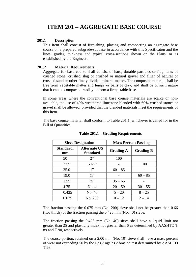
The base course material shall conform to Table 201.1, whichever is called for in the
Bill of Quantities
Table 201.1 – Grading Requirements
Sieve Designation Mass Percent Passing
Standard,
mm
Alternate US
Standard Grading A Grading B
50 2” 100
37.5 1-1/2” - 100
25.0 1” 60 – 85 -
19.0 ¾” - 60 – 85
12.5 ½” 35 – 65 -
4.75 No. 4 20 – 50 30 – 55
0.425 No. 40 5 – 20 8 – 25
0.075 No. 200 0 – 12 2 – 14
The fraction passing the 0.075 mm (No. 200) sieve shall not be greater than 0.66
(two thirds) of the fraction passing the 0.425 mm (No. 40) sieve.
The fraction passing the 0.425 mm (No. 40) sieve shall have a liquid limit not
greater than 25 and plasticity index not greater than 6 as determined by AASHTO T
89 and T 90, respectively.
The coarse portion, retained on a 2.00 mm (No. 10) sieve shall have a mass percent
of wear not exceeding 50 by the Los Angeles Abrasion test determined by AASHTO
T 96.
127
The material passing the 19 mm (3/4 inch) sieve shall have a soaked CBR value of
not less than 80% as determined by AASHTO T 193. The CBR value shall be
obtained at the maximum dry density (MDD) as determined by AASHTO T 180,
Method D.
If filler, in addition to that naturally present, is necessary for meeting the grading
requirements or for satisfactory bonding, it shall be uniformly blended with the base
course material on the road or in a pugmill unless otherwise specified or approved.
Filler shall be taken from sources approved by the Engineer, shall be free from hard
lumps and shall not contain more than 15 percent of material retained on the 4.75
mm (No. 4) sieve.
201.3 Construction Requirements
201.3.1 Preparation of Existing Surface
The existing surface shall be graded and finished as provided under Item 105,
Subgrade Preparation, before placing the base material.
201.3.2 Placing
It shall be in accordance with all the requirements of Subsection 200.3.2,
Placing.
201.3.3 Spreading and Compacting
It shall be in accordance with all the requirements of Subsection 200.3.3,
Spreading and Compacting.
201.3.4 Trial Sections
Trial sections shall conform in all respects to the requirements specified in
Subsection 200.3.4.
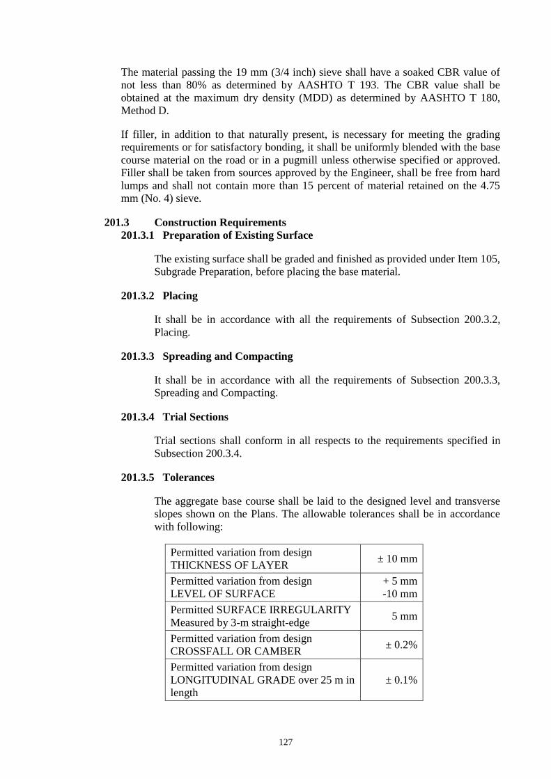
201.3.5 Tolerances
The aggregate base course shall be laid to the designed level and transverse
slopes shown on the Plans. The allowable tolerances shall be in accordance
with following:
Permitted variation from design
THICKNESS OF LAYER ± 10 mm
Permitted variation from design
LEVEL OF SURFACE
+ 5 mm
-10 mm
Permitted SURFACE IRREGULARITY
Measured by 3-m straight-edge 5 mm
Permitted variation from design
CROSSFALL OR CAMBER ± 0.2%
Permitted variation from design
LONGITUDINAL GRADE over 25 m in
length
± 0.1%

128
201.4 Method of Measurement
Aggregate Base Course will be measured by the cubic meter (m3). The quantity to be
paid for shall be the design volume compacted in-place as shown on the Plans, and
accepted in the completed base course. No allowance shall be given for materials
placed outside the design limits shown on the cross-sections. Trial sections shall not
be measured separately but shall be included in the quantity of aggregate base
course.
201.5 Basis of Payment
The accepted quantities, measured as prescribed in Section 201.4, shall be paid for at
the contract unit price for Aggregate Base Course which price and payment shall be
full compensation for furnishing and placing all materials, including all labor,
equipment, tools and incidentals necessary to complete the work prescribed in this
Item.
Payment will be made under:
Pay Item
Number Description
Unit of
Measurement
201 Aggregate Base Course Cubic Meter

129
ITEM 311 – PORTLAND CEMENT CONCRETE
PAVEMENT
311.1 Description
This Item shall consist of pavement of Portland Cement Concrete, with or without
reinforcement, constructed on the prepared base in accordance with this
Specification and in conformity with lines, grades, thickness and typical cross-
section shown on the Plans.
311.2 Material Requirements
311.2.1 Portland Cement
It shall conform to the applicable requirements of Item 700, Hydraulic
Cement. Only Type I Portland Cement shall be used unless otherwise
provided for in the Special Provisions. Different brands or the same brands
from different mills shall not be mixed nor shall they be used alternately
unless the mix is approved by the Engineer. However, the use of Portland
Pozzolan Cement Type IP meeting the requirements of AASHTO M
240/ASTM C 695, Specifications for Blended Hydraulic Cement shall be
allowed, provided that trial mixes shall be done and that the mixes meet the
concrete strength requirements, the AASHTO/ASTM provisions pertinent to
the use of Portland Pozzolan Type IP shall be adopted.
Cement which for any reason has become partially set or which contains
lumps of caked cement will be rejected. Cement salvaged from discarded or
used bags shall not be used.
Samples of Cement shall be obtained in accordance with AASHTO T 127.
311.2.2 Fine Aggregate
It shall consist of natural sand, stone screenings or other inert materials with
similar characteristics, or combinations thereof, having hard, strong and
durable particles. Fine aggregate from different sources of supply shall not be
mixed or stored in the same pile nor used alternately in the same class of
concrete without the approval of the Engineer.
It shall not contain more than three (3) mass percent of material passing the
0.075 mm (No. 200 sieve) by washing nor more than one (1) mass percent
each of clay lumps or shale. The use of beach sand will not be allowed
without the approval of the Engineer.
If the fine aggregate is subjected to five (5) cycles of the sodium sulfate
soundness test, the weighted loss shall not exceed 10 mass percent.
The fine aggregate shall be free from injurious amounts of organic
impurities. If subjected to the colorimatic test for organic impurities and a
color darker than the standard is produced, it shall be rejected. However,
when tested for the effect of organic impurities of strength of mortar by
130
AASHTO T 71, the fine aggregate may be used if the relative strength at 7
and 28 days is not less than 95 mass percent.
The fine aggregate shall be well-graded from course to fine and shall
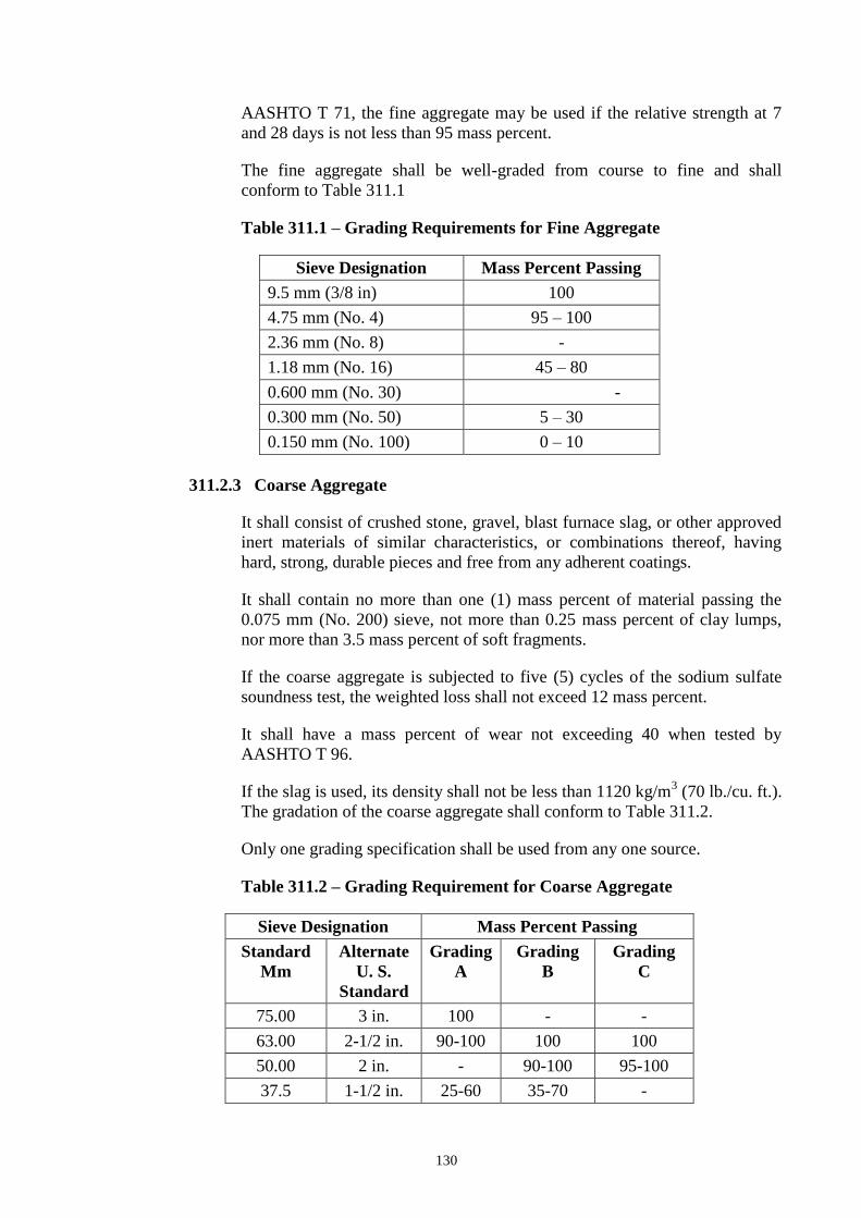
conform to Table 311.1
Table 311.1 – Grading Requirements for Fine Aggregate
Sieve Designation Mass Percent Passing
9.5 mm (3/8 in) 100
4.75 mm (No. 4) 95 – 100
2.36 mm (No. 8) -
1.18 mm (No. 16) 45 – 80
0.600 mm (No. 30) -
0.300 mm (No. 50) 5 – 30
0.150 mm (No. 100) 0 – 10
311.2.3 Coarse Aggregate
It shall consist of crushed stone, gravel, blast furnace slag, or other approved
inert materials of similar characteristics, or combinations thereof, having
hard, strong, durable pieces and free from any adherent coatings.
It shall contain no more than one (1) mass percent of material passing the
0.075 mm (No. 200) sieve, not more than 0.25 mass percent of clay lumps,
nor more than 3.5 mass percent of soft fragments.
If the coarse aggregate is subjected to five (5) cycles of the sodium sulfate
soundness test, the weighted loss shall not exceed 12 mass percent.
It shall have a mass percent of wear not exceeding 40 when tested by
AASHTO T 96.
If the slag is used, its density shall not be less than 1120 kg/m3 (70 lb./cu. ft.).
The gradation of the coarse aggregate shall conform to Table 311.2.
Only one grading specification shall be used from any one source.
Table 311.2 – Grading Requirement for Coarse Aggregate
Sieve Designation Mass Percent Passing
Standard
Mm
Alternate
U. S.
Standard
Grading
A
Grading
B
Grading
C
75.00 3 in. 100 - -
63.00 2-1/2 in. 90-100 100 100
50.00 2 in. - 90-100 95-100
37.5 1-1/2 in. 25-60 35-70 -

131
25.0 1 in. - 0-15 35-70
19.0 ¾ in. 0-10 - -
12.5 ½ in. 0-5 0-5 10-30
4.75 No. 4 - - 0-5
311.2.4 Water
Water used in mixing, curing or other designated application shall be
reasonably clean and free of oil, salt, acid, alkali, grass or other substances
injurious to the finished product. Water will be tested in accordance with and
shall meet the requirements of Item 714, Water. Water which is drinkable
may be used without test. Where the source of water is shallow, the intake
shall be so enclosed as to exclude silt, mud, grass or other foreign materials.
311.2.5 Reinforcing Steel
It shall conform to the requirements of Item 404, Reinforcing Steel. Dowels
and tie bars shall conform to the requirements of AASHTO M 31 or M 42,
except that rail steel shall not be used for tie bars that are to be bent and
restraightened during construction. Tie bars shall be deformed bars. Dowels
shall be plain round bars. Before delivery to the site of work, one-half of the
length of each dowel shall be painted with one coat of approved lead or tar
paint.
The sleeves for dowel bars shall be metal of approved design to cover 50 mm
(2 inches), plus or minus 5 mm (1/4 inch) of the dowel, with a closed end,
and with a suitable stop to hold the end of the sleeve at least 25 mm (1 inch)
from the end of the dowel. Sleeves shall be of such design that they do not
collapse during construction.
311.2.6 Joint Fillers
Poured joint fillers shall be mixed asphalt and mineral or rubber filler
conforming to the applicable requirements of Item 705, Joint Materials.
Preformed joint filler shall conform to the applicable requirements of Item
705. It shall be punched to admit the dowels where called for in the Plans.
The filler for each joint shall be furnished in a single piece for the full depth
and width required for the joint.
311.2.7 Admixtures
Air-entraining admixture shall conform to the requirements of AASHTO M
154.
Chemical admixtures, if specified or permitted, shall conform to the
requirements of AASHTO M 194.

132
Fly Ash, if specified or permitted as a mineral admixture and as 20% partial
replacement of Portland Cement in concrete mix shall conform to the
requirements of ASTM C 618.
Admixture should be added only to the concrete mix to produce some desired
modifications to the properties of concrete where necessary, but not as partial
replacement of cement.
311.2.8 Curing Materials
Curing materials shall conform to the following requirements as specified;
a) Burlap cloth - AASHTO M 182
b) Liquid membrane forming
compounds
- AASHTO M 148
c) Sheeting (film) materials - AASHTO M 171
Cotton mats and water-proof paper can be used.
311.2.9 Calcium Chloride/Calcium Nitrate
It shall conform to AASHTO M 144, if specified or permitted by the
Engineer, as accelerator.
311.2.10 Storage of Cement and Aggregate
All cement shall be stored, immediately upon delivery at the Site, in
weatherproof building which will protect the cement from dampness. The
floor shall be raised from the ground. The buildings shall be placed in
locations approved by the Engineer. Provisions for storage shall be ample,
and the shipments of cement as received shall be separately stored in such a
manner as to allow the earliest deliveries to be used first and to provide easy
access for identification and inspection of each shipment. Storage buildings
shall have capacity for storage of a sufficient quantity of cement to allow
sampling at least twelve (12) days before the cement is to be used. Bulk
cement, if used, shall be transferred to elevated air tight and weatherproof
bins. Stored cement shall meet the test requirements at any time after storage
when retest is ordered by the Engineer. At the time of use, all cement shall be
free-flowing and free of lumps.
The handling and storing of concrete aggregates shall be such as to prevent
segregation or the inclusion of foreign materials. The Engineer may require
that aggregates be stored on separate platforms at satisfactory locations.
In order to secure greater uniformity of concrete mix, the Engineer may
require that the coarse aggregate be separated into two or more sizes.
Different sizes of aggregate shall be stored in separate bins or in separate
stockpiles sufficiently removed from each other to prevent the material at the
edges of the piles from becoming intermixed.
133
311.2.11 Proportioning, Consistency and Strength of Concrete
The Contractor shall prepare the design mix based on the absolute volume
method as outlined in the American Concrete Institute (ACI) Standard 211.1,
“Recommended Practice for Selecting Proportions for Normal and
Heavyweight Concrete”.
It is the intent of this Specification to require at least 364 kg of cement per
cubic meter of concrete to meet the minimum strength requirements. The
Engineer shall determine from laboratory tests of the materials to be used, the
cement content and the proportions of aggregate and water that will produce
workable concrete having a slump of between 40 and 75 mm (1-1/2 and 3
inches) if not vibrated or between 10 and 40 mm (1/2 and 1-1/2 inches) if
vibrated, and a flexural strength of not less than 3.8 MPa (550 psi) when
tested by the third-point method or 4.5 MPa (650 psi) when tested by the
mid-point method at fourteen (14) days in accordance with AASHTO T97
and T177, respectively; or a compressive strength of 24.1 MPa (3500 psi) for
cores taken at fourteen (14) days and tested in accordance with AASHTO
T24.
Slump shall be determined using AASHTO T 119.
The designer shall consider the use of lean concrete (econocrete) mixtures
using local materials or specifically modified conventional concrete mixes in
base course and in the lower course composite, monolithic concrete
pavements using a minimum of 75 mm (3 inches) of conventional concrete as
the surface course.
The mix design shall be submitted to the Engineer for approval and shall be
accompanied with certified test data from an approved laboratory
demonstrating the adequacy of the mix design. A change in the source of
materials during the progress of work may necessitate a new design mix.
311.3 Construction Requirements
311.3.1 Quality Control of Concrete
1. General
The Contractor shall be responsible for the quality control of all materials
during the handling, blending, and mixing and placement operations.
2. Quality Control Plan
The Contractor shall furnish the Engineer a Quality Control Plan detailing his
production control procedures and the type and frequency of sampling and
testing to insure that the concrete produces complies with the Specifications.
The Engineer shall be provided free access to recent plant production
records, and if requested, informational copies of mix design, materials
certifications and sampling and testing reports.

134
3. Qualification of Workmen
Experienced and qualified personnel shall perform all batching or mixing
operation for the concrete mix, and shall be present at the plant and job site to
control the concrete productions whenever the plant is in operation. They
shall be identified and duties defined as follows:
a. Concrete Batcher. The person performing the batching or mixing
operation shall be capable of accurately conducting aggregate surface
moisture determination and establishing correct scale weights for
concrete materials. He shall be capable of assuring that the
proportioned batch weights of materials are in accordance with the
mix design.
b. Concrete Technician. The person responsible for concrete
production control and sampling and testing for quality control shall
be proficient in concrete technology and shall have a sound
knowledge of the Specifications as they relate to concrete production.
He shall be capable of conducting tests on concrete and concrete
materials in accordance with these Specifications. He shall be capable
of adjusting concrete mix designs for improving workability and
Specification compliance and preparing trial mix designs. He shall be
qualified to act as the concrete batcher in the batcher’s absence.
4. Quality Control Testing
The Contractor shall perform all sampling, testing and inspection necessary
to assure quality control of the component materials and the concrete.
The Contractor shall be responsible for determining the gradation of fine and
coarse aggregates and for testing the concrete mixture for slump, air content,
water-cement ratio and temperature. He shall conduct his operations so as to
produce a mix conforming to the approved mix design.
5. Documentation
The Contractor shall maintain adequate records of all inspections and tests.
The records shall indicate the nature and number of observations made, the
number and type of deficiencies found, the quantities approved and rejected,
and nature of any corrective action taken.
The Engineer may take independent assurance samples at random location
for acceptance purposes as he deems necessary.
311.3.2 Equipment
Equipment and tools necessary for handling materials and performing all
parts of the work shall be approved by the Engineer as to design, capacity
and mechanical condition. The equipment shall be at the jobsite sufficiently
ahead of the start of construction operations to be examined thoroughly and
approved.

135
1. Batching Plant and Equipment
a. General. The batching shall include bins, weighing hoppers, and
scales for the fine aggregate and for each size of coarse aggregate. If
cement is used in bulk, a bin, a hopper, and separate scale for cement
shall be included. The weighing hopper shall be properly sealed and
vented to preclude dusting operation. The batch plant shall be
equipped with a suitable non-resettable batch counter which will
correctly indicate the number of batches proportioned.
b. Bins and Hoppers. Bins with adequate separate compartments for
fine aggregate and for each size of coarse aggregate shall be provided
in the batching plant.
c. Scales. Scales for weighing aggregates and cement shall be of
either the beam type or the springless-dial type. They shall be
accurate within one-half percent (0.5%) throughout the range of use.
Poises shall be designed to be locked in any position and to prevent
unauthorized change.
Scales shall be inspected and sealed as often as the Engineer may
deem necessary to assure their continued accuracy.
d. Automatic Weighing Devices. Unless otherwise allowed on the
Contract, batching plants shall be equipped with automatic weighing
devices of an approved type to proportion aggregates and bulk
cement.
2. Mixers.
a. General. Concrete may be mixed at the Site of construction or at a
central plant, or wholly or in part in truck mixers. Each mixer shall
have a manufacturer’s plate attached in a prominent place showing
the capacity of the drum in terms of volume of mixed concrete and
the speed of rotation of the mixing drum or blades.
b. Mixers at Site of Construction. Mixing shall be done in an
approved mixer capable of combining the aggregates, cement and
water into a thoroughly mixed and uniform mass within the specified
mixing period and discharging and distributing the mixture without
segregation on the prepared grade. The mixer shall be equipped with
an approved timing device which will automatically lock the
discharge lever when the drum has been charged and released it at the
end of the mixing period. In case of failure of the timing device, the
mixer may be used for the balance of the day while it is being
repaired, provided that each batch is mixed 90 seconds. The mixer
shall be equipped with a suitable nonresettable batch counter which
shall correctly indicate the number of the batches mixed.
c. Truck Mixer and Truck Agitators. Truck mixers used for mixing
and hauling concrete, and truck agitators used for hauling central-
136
mixed concrete, shall conform to the requirements of AASHTO M
157.
d. Non-Agitator Truck. Bodies of non-agitating hauling equipment for
concrete shall be smooth, mortar-tight metal containers and shall be
capable of discharging the concrete at a satisfactory controlled rate
without segregation.
3. Paving and Finishing Equipment
The concrete shall be placed with an approved paver designed to spread,
consolidate, screed and float finish the freshly placed concrete in one
complete pass of the machine in such a manner that a minimum of hand
finishing will be necessary to provide a dense and homogeneous pavement in
conformance with the Plans and Specifications.
The finishing machine shall be equipped with at least two (2) oscillating type
transverse screed.
Vibrators shall operate at a frequency of 8,300 to 9,600 impulses per minute
under load at a maximum spacing of 60 cm.
4. Concrete Saw
The Contractor shall provide sawing equipment in adequate number of units
and power to complete the sawing with a water-cooled diamond edge saw
blade or an abrasive wheel to the required dimensions and at the required
rate. He shall provide at least one (1) stand-by saw in good working
condition and with an ample supply of saw blades.
5. Forms
Forms shall be of steel, of an approved section, and of depth equal to the
thickness of the pavement at the edge. The base of the forms shall be of
sufficient width to provide necessary stability in all directions. The flange
braces must extend outward on the base to not less than 2/3 the height of the
form.
All forms shall be rigidly supported on bed of thoroughly compacted material
during the entire operation of placing and finishing the concrete. Forms shall
be provided with adequate devices for secure setting so that when in place,
they will withstand, without visible spring or settlement, the impact and
vibration of the consolidation and finishing or paving equipment.
311.3.3 Preparation of Grade
After the subgrade of base has been placed and compacted to the required
density, the areas which will support the paving machine and the grade on
which the pavement is to be constructed shall be trimmed to the proper
elevation by means of a properly designed machine extending the prepared
work areas compacted at least 60 cm beyond each edge of the proposed
concrete pavement. If loss of density results from the trimming operations, it

137
shall be restored by additional compaction before concrete is placed. If any
traffic is allowed to use the prepared subgrade or base, the surface shall be
checked and corrected immediately ahead of the placing concrete.
The subgrade or base shall be uniformly moist when the concrete is placed.
311.3.4 Setting Forms
1. Base Support.
The foundation under the forms shall be hard and true to grade so that the
form when set will be firmly in contact for its whole length and at the
specified grade. (Any roadbed, which at the form line is found below
established grade, shall be filled with approved granular materials to grade in
lifts of three (3) cm or less, and thoroughly rerolled or tamped.)
Imperfections or variations above grade shall be corrected by tamping or by
cutting as necessary.
2. Form Setting
Forms shall be set sufficiently in advance of the point where concrete is
being placed. After the forms have been set to correct grade, the grade shall
be thoroughly tamped, mechanically or by hand, at both the inside and
outside edges of the base of the forms. The forms shall not deviate from true
line by more than one (1) cm at any point.
3. Grade and Alignment
The alignment and grade elevations of the forms shall be checked and
corrections made by the Contractor immediately before placing the concrete.
Testing as to crown and elevation, prior to placing of concrete can be made
by means of holding an approved template in a vertical position and moved
backward and forward on the forms.
When any form has been disturbed or any grade has become unstable, the
form shall be reset and rechecked.
311.3.5 Conditioning of Subgrade or Base Course
When side forms have been securely set to grade, the subgrade or base course
shall be brought to proper cross-section. High areas shall be trimmed to
proper elevation. Low areas shall be filled and compacted to a condition
similar to that of surrounding grade. The finished grade shall be maintained
in a smooth and compacted condition until the pavement is placed.
Unless waterproof subgrade or base course cover material is specified, the
subgrade or base course shall be uniformly moist when the concrete is
placed. If it subsequently becomes too dry, the subgrade or base course shall
be sprinkled, but the method of sprinkling shall not be such as to form mud
or pools of water.

138
311.3.6 Handling, Measuring and Batching Materials
The batch plant site, layout, equipment and provisions for transporting
material shall be such as to assure a continuous supply of material to the
work.
Stockpiles shall be built up in layers of not more than one (1) meter in
thickness. Each layer shall be completely in place before beginning the next
which shall not be allowed to “cone” down over the next lower layer.
Aggregates from different sources and of different grading shall not be
stockpiled together.
All washed aggregates and aggregates produced or handled by hydraulic
methods, shall be stockpiled or binned for draining at least twelve (12) hours
before being batched.
When mixing is done at the side of the work, aggregates shall be transported
from the batching plant to the mixer in batch boxes, vehicle bodies, or other
containers of adequate capacity and construction to properly carry the
volume required. Partitions separating batches shall be adequate and effective
to prevent spilling from one compartment to another while in transit or being
dumped. When bulk cement is used, the Contractor shall use a suitable
method of handling the cement from weighing hopper to transporting
container or into the batch itself for transportation to the mixer, with chute,
boot or other approved device, to prevent loss of cement, and to provide
positive assurance of the actual presence in each batch of the entire cement
content specified.
Bulk cement shall be transported to the mixer in tight compartments carrying
the full amount of cement required for the batch. However, if allowed in the
Special Provisions, it may be transported between the fine and coarse
aggregate. When cement is placed in contact with the aggregates, batches
may be rejected unless mixed within 1-1/2 hours of such contact. Cement in
original shipping packages may be transported on top of the aggregates, each
batch containing the number of sacks required by the job mix.
The mixer shall be charged without loss of cement. Batching shall be so
conducted as to result in the weight to each material required within a
tolerance of one (1) percent for the cement and two (2) percent for
aggregates.
Water may be measured either by volume or by weight. The accuracy of
measuring the water shall be within a range of error of not over than one (1)
percent. Unless the water is to be weighed, the water-measuring equipment
shall include an auxiliary tank from which the measuring tank shall be
equipped with an outside tap and valve to provide checking the setting,
unless other means are provided for readily and accurately determining the
amount of water in the tank. The volume of the auxiliary tank shall be at least
equal to that of the measuring tank.
139
311.3.7 Mixing Concrete
The concrete may be mixed at the site of the work in a central-mix plant, or
in truck mixers. The mixer shall be of an approved type and capacity. Mixing
time will be measured from the time all materials, except water, are in the
drum. Ready-mixed concrete shall be mixed and delivered in accordance
with requirements of AASHTO M 157, except that the minimum required
revolutions at the mixing speed for transit-mixed concrete may be reduced to
not less than that recommended by the mixer manufacturer. The number of
revolutions recommended by the mixer manufacturer shall be indicated on
the manufacturer’s serial plate attached to the mixer. The Contractor shall
furnish test data acceptable to the Engineer verifying that the make and
model of the mixer will produce uniform concrete conforming to the
provision of AASHTO M 157 at the reduced number of revolutions shown
on the serial plate.
When mixed at the site or in a central mixing plant, the mixing time shall not
be less than fifty (50) seconds nor more than ninety (90) seconds, unless
mixer performance tests prove adequate mixing of the concrete is a shorter
time period.
Four (4) seconds shall be added to the specified mixing time if timing starts
at the instant the skip reaches its maximum raised positions. Mixing time
ends when the discharge chute opens. Transfer time in multiple drum mixers
is included in mixing time. The contents of an individual mixer drum shall be
removed before a succeeding batch is emptied therein.
The mixer shall be operated at the drum speed as shown on the
manufacturer’s name plate attached on the mixer. Any concrete mixed less
than the specified time shall be discarded and disposed off by the Contractor
at his expense. The volume of concrete mixed per batch shall not exceed the
mixer’s nominal capacity in cubic metre, as shown on the manufacturer’s
standard rating plate on the mixer, except that an overload up to ten (10)
percent above the mixer’s nominal capacity may be permitted provided
concrete test data for strength, segregation, and uniform consistency are
satisfactory, and provided no spillage of concrete takes place.
The batches shall be so charged into the drum that a portion of the mixing
water shall be entered in advance of the cement and aggregates. The flow of
water shall be uniform and all water shall be in the drum by the end of the
first fifteen (15) seconds of the mixing period. The throat of the drum shall
be kept free of such accumulations as may restrict the free flow of materials
into the drum.
Mixed concrete from the central mixing plant shall be transported in truck
mixers, truck agitators or non-agitating truck specified in Subsection 311.3.2,
Equipment. The time elapsed from the time water is added to the mix until
the concrete is deposited in place at the Site shall not exceed forty five (45)
minutes when the concrete is hauled in non-agitating trucks, nor ninety (90)
minutes when hauled in truck mixers or truck agitators, except that in hot

140
weather or under other conditions contributing to quick hardening of the
concrete, the maximum allowable time may be reduced by the Engineer.
In exceptional cases and when volumetric measurements are authorized for
small project requiring less than 75 cu.m. of concrete per day of pouring, the
weight proportions shall be converted to equivalent volumetric proportions.
In such cases, suitable allowance shall be made for variations in the moisture
condition of the aggregates, including the bulking effect in the fine
aggregate. Batching and mixing shall be in accordance with ASTM C 685,
Section 6 through 9.
Concrete mixing by chute is allowed provided that a weighing scales for
determining the batch weight will be used.
Retempering concrete by adding water or by other means shall not be
permitted, except that when concrete is delivered in truck mixers, additional
water may be added to the batch materials and additional mixing performed
to increase the slump to meet the specified requirements, if permitted by the
Engineer, provided all these operations are performed within forty-five (45)
minutes after the initial mixing operation and the water-cement ratio is not
exceeded. Concrete that is not within the specified slump limits at the time of
placement shall not be used. Admixtures for increasing the workability or for
accelerating the setting of the concrete will be permitted only when
specifically approved by the Engineer.
311.3.8 Limitation of Mixing
No concrete shall be mixed, placed or finished when natural light is
insufficient, unless an adequate and approved artificial lighting system is
operated.
During hot weather, the Engineer shall require that steps be taken to prevent
the temperature of mixed concrete from exceeding a maximum temperature
of 900F (32
0C)
Concrete not in place within ninety (90) minutes from the time the
ingredients were charged into the mixing drum or that has developed initial
set shall not be used. Retempering of concrete or mortar which has partially
hardened, that is remixing with or without additional cement, aggregate, or
water, shall not be permitted.
In order that the concrete may be properly protected against the effects of
rain before the concrete is sufficiently hardened, the Contractor will be
required to have available at all times materials for the protection of the
edges and surface of the unhardened concrete.
311.3.9 Placing Concrete
Concrete shall be deposited in such a manner to require minimal rehandling.
Unless truck mixers or non-agitating hauling equipment are equipped with
means to discharge concrete without segregation of the materials, the

141
concrete shall be unloaded into an approved spreading device and
mechanically spread on the grade in such a manner as to prevent segregation.
Placing shall be continuous between transverse joints without the use of
intermediate bulkheads. Necessary hand spreading shall be done with
shovels, not rakes. Workmen shall not be allowed to walk in the freshly
mixed concrete with boots or shoes coated with earth or foreign substances.
When concrete is to be placed adjoining a previously constructed lane and
mechanical equipment will be operated upon the existing lane, that
previously constructed lane shall have attained the strength for fourteen (14)
day concrete. If only finishing equipment is carried on the existing lane,
paving in adjoining lanes may be permitted after three (3) days.
Concrete shall be thoroughly consolidated against and along the faces of all
forms and along the full length and on both sides of all joint assemblies, by
means of vibrators inserted in the concrete. Vibrators shall not be permitted
to come in contact with a joint assembly, the grade, or a side form. In no case
shall the vibrator be operated longer than fifteen (15) seconds in any one
location.
Concrete shall be deposited as near as possible to the expansion and
contraction joints without disturbing them, but shall not be dumped from the
discharge bucket or hopper into a joint assembly unless the hopper is well
centered on the joint assembly. Should any concrete material fall on or be
worked into the surface of a complete slab, it shall be removed immediately.
311.3.10 Test Specimens
As work progresses, at least one (1) set consisting of three (3) concrete beam
test specimens, 150 mm x 150 mm x 525 mm or 900 mm shall be taken from
each 330 m2 of pavement, 230 mm depth, or fraction thereof placed each day.
Test specimens shall be made under the supervision of the Engineer, and the
Contractor shall provide all concrete and other facilities necessary in making
the test specimens and shall protect them from damage by construction
operations. Cylinder samples shall not be used as substitute for determining
the adequacy of the strength of concrete.
The beams shall be made, cured, and tested in accordance with AASHTO T
23 and T 97.
311.3.11 Strike-off of Concrete and Placement of Reinforcement
Following the placing of the concrete, it shall be struck off to conform to the
cross-section shown on the Plans and to an elevation such that when the
concrete is properly consolidated and finished, the surface of the pavement
will be at the elevation shown on the Plans. When reinforced concrete
pavement is placed in two (2) layers, the bottom layer shall be struck off and
consolidated to such length and depth that the sheet of fabric or bar mat may
be laid full length on the concrete in its final position without further
manipulation. The reinforcement shall then be placed directly upon the

142
concrete, after which the top layer of the concrete shall be placed, struck off
and screeded. Any portion of the bottom layer of concrete which has been
placed more than 30 minutes without being covered with the top layer shall
be removed and replaced with freshly mixed concrete at the Contractor’s
expense. When reinforced concrete is placed in one layer, the reinforcement
may be firmly positioned in advance of concrete placement or it may be
placed at the depth shown on the Plans in plastic concrete, after spreading by
mechanical or vibratory means.
Reinforcing steel shall be free from dirt, oil, paint, grease, mill scale and
loose or thick rust which could impair bond of the steel with the concrete.
311.3.12 Joints
Joints shall be constructed of the type and dimensions, and at the locations
required by the Plans or Special Provisions. All joints shall be protected from
the intrusion of injurious foreign material until sealed.
1. Longitudinal Joint
Deformed steel tie bars of specified length, size, spacing and
materials shall be placed perpendicular to the longitudinal joints, they
shall be placed by approved mechanical equipment or rigidly secured
by chair or other approved supports to prevent displacement. Tie bars
shall not be painted or coated with asphalt or other materials or
enclosed in tubes or sleeves. When shown on the Plans and when
adjacent lanes of pavement are constructed separately, steel side
forms shall be used which will form a keyway along the construction
joint. Tie bars, except those made of rail steel, may be bent at right
angles against the form of the first lane constructed and straightened
into final position before the concrete of the adjacent lane is placed,
or in lieu of bent tie bars, approved two-piece connectors may be
used.
Longitudinal formed joints shall consist of a groove or cleft,
extending downward from and normal to, the surface of the
pavement. These joints shall be effected or formed by an approved
mechanically or manually operated device to the dimensions and line
indicated on the Plans and while the concrete is in a plastic state. The
groove or cleft shall be filled with either a premolded strip or poured
material as required.
The longitudinal joints shall be continuous, there shall be no gaps in
either transverse or longitudinal joints at the intersection of the joints.
Longitudinal sawed joints shall be cut by means of approved concrete
saws to the depth, width and line shown on the Plans. Suitable guide
lines or devices shall be used to assure cutting the longitudinal joint
on the true line. The longitudinal joint shall be sawed before the end
of the curing period or shortly thereafter and before any equipment or
vehicles are allowed on the pavement. The sawed area shall be

143
thoroughly cleaned and, if required, the joint shall immediately be
filled with sealer.
Longitudinal pavement insert type joints shall be formed by placing a
continuous strip of plastic materials which will not react adversely
with the chemical constituent of the concrete.
2. Transverse Expansion Joint
The expansion joint filler shall be continuous from form to form,
shaped to subgrade and to the keyway along the form. Preformed
joint filler shall be furnished in lengths equal to the pavement width
or equal to the width of one lane. Damaged or repaired joint filler
shall not be used.
The expansion joint filler shall be held in a vertical position. An
approved installing bar, or other device, shall be used if required to
secure preformed expansion joint filler at the proper grade and
alignment during placing and finishing of the concrete. Finished joint
shall not deviate more than 6 mm from a straight line. If joint fillers
are assembled in sections, there shall be no offsets between adjacent
units. No plugs of concrete shall be permitted anywhere within the
expansion space.
3. Transverse Contraction Joint/Weakened Joint
When shown on the Plans, it shall consist of planes of weakness
created by forming or cutting grooves in the surface of the pavement
and shall include load transfer assemblies. The depth of the weakened
plane joint should at all times not be less than 50 mm, while the width
should not be more than 6 mm.
1. a. Transverse Strip Contraction Joint. It shall be
formed by installing a parting strip to be left in place as shown
on the Plans.
2. b. Formed Groove. It shall be made by depressing an
approved tool or device into the plastic concrete. The tool or
device shall remain in place at least until the concrete has
attained its initial set and shall then be removed without
disturbing the adjacent concrete, unless the device is designed
to remain in the joint.
3. c. Sawed Contraction Joint. It shall be created by
sawing grooves in the surface of the pavement of the width
not more than 6 mm, depth should at all times not be less than
50 mm, and at the spacing and lines shown on the Plans, with
an approved concrete saw. After each joint is sawed, it shall
be thoroughly cleaned including the adjacent concrete surface.
4. Sawing of the joint shall commence as soon as the
concrete has hardened sufficiently to permit sawing without
excessive ravelling, usually 4 to 24 hours. All joints shall be
sawed before uncontrolled shrinkage cracking takes place. If
144
necessary, the sawing operations shall be carried on during the
day or night, regardless of weather conditions. The sawing of
any joint shall be omitted if crack occurs at or near the joint
location prior to the time of sawing. Sawing shall be
discounted when a crack develops ahead of the saw. In
general, all joints should be sawed in sequence. If extreme
condition exist which make it impractical to prevent erratic
cracking by early sawing, the contraction joint groove shall be
formed prior to initial set of concrete as provided above.
4. Transverse Construction Joint
It shall be constructed when there is an interruption of more than 30
minutes in the concreting operations. No transverse joint shall be
constructed within 1.50 m of an expansion joint, contraction joint, or
plane of weakness. If sufficient concrete has been mixed at the time
of interruption to form a slab of at least 1.5 m long, the excess
concrete from the last preceding joint shall be removed and disposed
off as directed.
5. Load Transfer Device
Dowel, when used, shall be held in position parallel to the surface and
center line of the slab by a metal device that is left in the pavement.
The portion of each dowel painted with one coat of lead or tar, in
conformance with the requirements of Item 404, Reinforcing Steel,
shall be thoroughly coated with approved bituminous materials, e.g.,
MC-70, or an approved lubricant, to prevent the concrete from
binding to that portion of the dowel. The sleeves for dowels shall be
metal designed to cover 50 mm plus or minus 5 mm (1/4 inch), of the
dowel, with a watertight closed end and with a suitable stop to hold
the end of the sleeves at least 25 mm (1 inch) from the end of the
dowel.
In lieu of using dowel assemblies at contraction joints, dowel may be
placed in the full thickness of pavement by a mechanical device
approved by the Engineer.
311.3.13 Final Strike-off (Consolidation and Finishing)
1. Sequence
The sequence of operations shall be the strike-off and consolidation, floating
and removal of laitance, straight-edging and final surface finish. Work
bridges or other devices necessary to provide access to the pavement surface
for the purpose of finishing straight-edging, and make corrections as
hereinafter specified, shall be provided by the Contractor.
In general, the addition of water to the surface of the concrete to assist in
finishing operations will not be permitted. If the application of water to the

145
surface is permitted, it shall be applied as fog spray by means of an approved
spray equipment.
2. Finishing Joints
The concrete adjacent to joints shall be compacted or firmly placed without
voids or segregation against the joint material assembly, also under and
around all load transfer devices, joint assembly units, and other features
designed to extend into the pavement. Concrete adjacent to joints shall be
mechanically vibrated as required in Subsection 311.3.9, Placing Concrete.
After the concrete has been placed and vibrated adjacent to the joints as
required in Subsection 311.3.9, the finishing machine shall be brought
forward, operating in a manner to avoid damage or misalignment of joints. If
uninterrupted operation of the finishing machine, to over and beyond the
joints causes segregation of concrete, damage to, or misalignment of the
joints, the finishing machine shall be stopped when the front screed is
approximately 20 cm (8 inches) from the joint. Segregated concrete shall be
removed from in front of and off the joint. The front screed shall be lifted and
set directly on top of the joint and the forward motion of the finishing
machine resumed. When the second screed is close enough to permit the
excess mortar in front of it to flow over the joint, it shall be lifted and carried
over the joint. Thereafter, the finishing machine may be run over the joint
without lifting the screeds, provided there is no segregated concrete
immediately between the joint and the screed or on top of the joint.
3. Machine Finishing
a. Non-vibratory Method. The concrete shall be distributed or spread
as soon as placed. As soon as the concrete has been placed, it shall be
struck off and screeded by an approved finishing machine. The
machine shall go over each area of pavement as many times and at
such intervals as necessary to give the proper compaction and leave a
surface of uniform texture. Excessive operation over a given area
shall be avoided. The tops of the forms shall be kept clean by an
effective device attached to the machine and the travel of the machine
on the forms shall be maintained true without wobbling or other
variation tending to affect the precision finish.
During the first pass of the finishing machine, a uniform ridge of
concrete shall be maintained ahead of the front screed in its entire
length.
b. Vibratory Method. When vibration is specified, vibrators for full
width vibration of concrete paving slabs, shall meet the requirements
in Subsection 311.3.2, Equipment. If uniform and satisfactory density
of the concrete is not obtained by the vibratory method at joints,
along forms, at structures, and throughout the pavement, the
Contractor will be required to furnish equipment and method which
will produce pavement conforming to the Specifications. All

146
provisions in item (a) above not in conflict with the provisions for the
vibratory method shall govern.
4. Hand Finishing
Hand finishing methods may only be used under the following conditions:
a. In the event of breakdown of the mechanical equipment, hand
methods may be used to finish the concrete already deposited on the
grade.
b. In narrow widths or areas of irregular dimensions where operations
of the mechanical equipment is impractical, hand methods may be
used.
Concrete, as soon as placed, shall be struck off and screeded. An approved
portable screed shall be used. A second screed shall be provided for striking
off the bottom layer of concrete if reinforcement is used.
The screed for the surface shall be at least 60 cm (2 feet) longer than the
maximum width of the slab to be struck off. It shall be of approved design,
sufficiently rigid to retain its shape, and constructed either of metal or other
suitable material shod with metal.
Consolidation shall be attained by the use of suitable vibrator or other
approved equipment.
In operation, the screed shall be moved forward on the forms with a
combined longitudinal and transverse shearing motion, moving always in the
direction in which the work is progressing and so manipulated that neither
end is raised from the side forms during the striking off process. If necessary,
this shall be repeated until the surface is of uniform texture, true to grade and
cross-section, and free from porous areas.
5. Floating
After the concrete has been struck off and consolidated, it shall be further
smoothed, trued, and consolidated by means of a longitudinal float, either by
hand or mechanical method.
a. Hand Method. The hand-operated longitudinal float shall be not
less than 365 cm (12 feet) in length and 15 cm (6 inches) in width,
properly stiffened to prevent flexibility and warping. The longitudinal
float, operated from foot bridges resting on the side forms and
spanning but not touching the concrete, shall be worked with a
sawing motion while held in a floating position parallel to the road
center line, and moving gradually from one side of the pavement to
the other. Movement ahead along the center line of the pavement
shall be in successive advances of not more than one-half the length
of the float. Any excess water or soupy material shall be wasted over
the side forms on each pass.
147
b. Mechanical Method. The mechanical longitudinal float shall be of
a design approved by the Engineer, and shall be in good working
condition. The tracks from which the float operates shall be
accurately adjusted to the required crown. The float shall be
accurately adjusted and coordinated with the adjustment of the
transverse finishing machine so that a small amount of mortar is
carried ahead of the float at all times. The forward screed shall be
adjusted so that the float will lap the distance specified by the
Engineer on each transverse trip. The float shall pass over each areas
of pavement at least two times, but excessive operation over a given
area will not be permitted. Any excess water or soupy material shall
be wasted over the side forms on each pass.
c. Alternative Mechanical Method. As an alternative, the Contractor
may use a machine composed of a cutting and smoothing float or
floats suspended from and guided by a rigid frame. The frame shall
be carried by four or more visible wheels riding on, and constantly in
contact with the side forms. If necessary, following one of the
preceding method of floating, long handled floats having blades not
less than 150 cm (5 feet) in length and 15 cm (6 inches) in width may
be used to smooth and fill in open-textured areas in the pavement.
Long-handled floats shall not be used to float the entire surface of the
pavement in lieu of, or supplementing, one of the preceding methods
of floating. When strike off and consolidation are done by the hand
method and the crown of the pavement will not permit the use of the
longitudinal float, the surface shall be floated transversely by means
of the long-handled float. Care shall be taken not to work the crown
out of the pavement during the operation. After floating, any excess
water and laitance shall be removed from the surface of the pavement
by a 3-m straight-edge or more in length. Successive drags shall be
lapped one-half the length of the blade.
6. Straight-edge Testing and Surface Correction
After the floating has been completed and the excess water removed, but
while the concrete is still plastic, the surface of the concrete shall be tested
for trueness with a 300 cm long straight-edge. For this purpose, the
Contractor shall furnish and use an accurate 300-cm straight-edge swung
from handles 100 cm (3 feet) longer than one-half the width of the slab. The
straight-edge shall be held in contact with the surface in successive positions
parallel to the road center line and the whole area gone over from one side of
the slab to the other as necessary. Advances along the road shall be in
successive stages of not more than one-half the length of the straight-edge.
Any depressions found shall be immediately filled with freshly mixed
concrete, struck off, consolidated and refinished. High areas shall be cut
down and refinished. Special attention shall be given to assure that the
surface across joints meets the requirements for smoothness. Straight-edge
testing and surface corrections shall continue until the entire surface is found
to be free from observable departures from the straight-edge and the slab
conforms to the required grade and cross-section.

148
7. Final Finish
If the surface texture is broom finished, it shall applied when the water sheen
has practically disappeared. The broom shall be drawn from the center to the
edge of the pavement with adjacent strokes slightly overlapping. The
brooming operation should be so executed that the corrugations produced in
the surface shall be uniform in appearance and not more than 1.5 mm in
depth. Brooming shall be completed before the concrete is in such condition
that the surface will be unduly roughened by the operation. The surface thus
finished shall be free from rough and porous areas, irregularities, and
depressions resulting from improper handling of the broom. Brooms shall be
of the quality size and construction and be operated so as to produce a
surface finish meeting the approval of the Engineer. Subject to satisfactory
results being obtained and approval of the Engineer, the Contractor will be
permitted to substitute mechanical brooming in lieu of the manual brooming
herein described.
If the surface texture is belt finished, when straight-edging is complete and
water sheen has practically disappeared and just before the concrete becomes
non-plastic, the surface shall be belted with 2-ply canvass belt not less than
20 cm wide and at least 100 cm longer than the pavement width. Hand belts
shall have suitable handles to permit controlled, uniform manipulation. The
belt shall be operated with short strokes transverse to the center line and with
a rapid advances parallel to the center line.
If the surface texture is drag finished, a drag shall be used which consists of a
seamless strip of damp burlap or cotton fabric, which shall produce a uniform
of gritty texture after dragging it longitudinally along the full width of
pavement. For pavement 5 m or more in width, the drag shall be mounted on
a bridge which travels on the forms. The dimensions of the drag shall be such
that a strip of burlap or fabric at least 100 cm wide is in contact with the full
width of pavement surface while the drag is used. The drag shall consist of
not less than 2 layers of burlap with the bottom layer approximately 15 cm
wider than the layer. The drag shall be maintained in such condition that the
resultant surface is of uniform appearance and reasonably free from grooves
over 1.5 mm in depth. Drag shall be maintained clean and free from
encrusted mortar. Drags that cannot be cleaned shall be discarded and new
drags be substituted.
Regardless of the method used for final finish, the hardened surface of
pavement shall have a coefficient of friction of 0.25 or more. Completed
pavement that is found to have a coefficient of friction less than 0.25 shall be
grounded or scored by the Contractor at his expense to provide the required
coefficient of friction.
8. Edging at Forms and Joints
After the final finish, but before the concrete has taken its initial set, the
edges of the pavement along each side of each slab, and on each side of
transverse expansion joints, formed joints, transverse construction joints, and
emergency construction joints, shall be worked with an approved tool and
149
rounded to the radius required by the Plans. A well – defined and continuous
radius shall be produced and a smooth, dense mortar finish obtained. The
surface of the slab shall not be unduly disturbed by tilting the tool during the
use.
At all joints, any tool marks appearing on the slab adjacent to the joints shall
be eliminated by brooming the surface. In doing this, the rounding of the
corner of the slab shall not be disturbed. All concrete on top of the joint filler
shall be completely removed.
All joints shall be tested with a straight-edge before the concrete has set and
correction made if one edge of the joint is higher than the other.
311.3.14 Surface Test
As soon as the concrete has hardened sufficiently, the pavement surface shall
be tested with a 3-m straight-edge or other specified device. Areas showing
high spots of more than 3 mm but not exceeding 12 mm in 3 m shall be
marked and immediately ground down with an approved grinding tool to an
elevation where the area or spot will not show surface deviations in excess of
3 mm when tested with 3 m straight-edge. Where the departure from correct
cross-section exceeds 12 mm, the pavement shall be removed and replaced
by and at the expense of the Contractor.
Any area or section so removed shall be not less than 1.5 m in length and not
less than the full width of the lane involved. When it is necessary to remove
and replace a section of pavement, any remaining portion of the slab adjacent
to the joints that is less than 1.5 m in length, shall also be removed and
replaced.
311.3.15 Curing
Immediately after the finishing operations have been completed and the
concrete has sufficiently set, the entire surface of the newly placed concrete
shall be cured in accordance with either one of the methods described herein.
Failure to provide sufficient cover material of whatever kind the Contractor
may elect to use, or the lack of water to adequately take care of both curing
and other requirements, shall be a cause for immediate suspension of
concreting operations. The concrete shall not be left exposed for more than ½
hour between stages of curing or during the curing period.
In all congested places, concrete works should be designed so that the
designed strength is attained.
1. Cotton of Burlap Mats
The surface of the pavement shall be entirely covered with mats. The mats
used shall be of such length (or width) that as laid they will extend at least
twice the thickness of the pavement beyond the edges of the slab. The mat
shall be placed so that the entire surface and the edges of the slab are
completely covered. Prior to being placed, the mats shall be saturated
150
thoroughly with water. The mat shall be so placed and weighted down so as
to cause them to remain in intimate contact with the covered surface. The mat
shall be maintained fully wetted and in position for 72 hours after the
concrete has been placed unless otherwise specified.
2. Waterproof Paper
The top surface and sides of the pavement shall be entirely covered with
waterproof paper, the units shall be lapped at least 45 cm. The paper shall be
so placed and weighted down so as to cause it to remain in intimate contact
with the surface covered. The paper shall have such dimension but each unit
as laid will extend beyond the edges of the slab at least twice the thickness of
the pavement, or at pavement width and 60 cm strips of paper for the edges.
If laid longitudinally, paper not manufactured in sizes which will provide this
width shall be securely sewed or cemented together, the joints being securely
sealed in such a manner that they do not open up or separate during the
curing period. Unless otherwise specified, the covering shall be maintained in
place for 72 hours after the concrete has been placed. The surface of the
pavement shall be thoroughly wetted prior to the placing of the paper.
3. Straw Curing
When this type of curing is used, the pavement shall be cured initially with
burlap or cotton mats, until after final set of the concrete or, in any case, for
12 hours after placing the concrete. As soon as the mats are removed, the
surface and sides of the pavement shall be thoroughly wetted and covered
with at least 20 cm of straw or hay, thickness of which is to be measured
after wetting. If the straw or hay covering becomes displaced during the
curing period, it shall be replaced to the original depth and saturated. It shall
be kept thoroughly saturated with water for 72 hours and thoroughly wetted
down during the morning of the fourth day, and the cover shall remain in
place until the concrete has attained the required strength.
4. Impervious Membrane Method
The entire surface of the pavement shall be sprayed uniformly with white
pigmented curing compound immediately after the finishing of the surface
and before the set of the concrete has taken place, or if the pavement is cured
initially with jute or cotton mats, it may be applied upon removal of the mass.
The curing compound shall not be applied during rain.
Curing compound shall be applied under pressure at the rate 4 L to not more
than 14 m2 by mechanical sprayers. The spraying equipment shall be
equipped with a wind guard. At the time of use, the compound shall be in a
thoroughly mixed condition with the pigment uniformly dispersed throughout
the vehicle. During application, the compound shall be stirred continuously
by effective mechanical means. Hand spraying of odd widths or shapes and
concrete surface exposed by the removal of forms will be permitted. Curing
compound shall not be applied to the inside faces of joints to be sealed, but
approved means shall be used to insure proper curing at least 72 hours and to
prevent the intrusion of foreign material into the joint before sealing has been

151
completed. The curing compound shall be of such character that the film will
harden within 30 minutes after application. Should the film be damaged from
any cause within the 72 hour curing period, the damaged portions shall be
repaired immediately with additional compound.
5. White Polyethylene Sheet
The top surface and sides of the pavement shall be entirely covered with
polyethylene sheeting. The units used shall be lapped at least 45 cm. The
sheeting shall be so placed and weighted down so as to cause it to remain
intimate contact with the surface covered. The sheeting as prepared for use
shall have such dimension that each unit as laid will extend beyond the edges
of the slab at least twice the thickness of the pavement. Unless otherwise
specified, the covering shall be maintained in place for 72 hours after the
concrete has been placed.
311.3.16 Removal of Forms
After forms for concrete shall remain in place undisturbed for not less than
twenty four (24) hours after concrete pouring. In the removal of forms,
crowbars should be used in pulling out nails and pins. Care should be taken
so as not to break the edges of the pavement. In case portions of the concrete
are spalled, they shall be immediately repaired with fresh mortar mixed in the
proportion of one part of Portland Cement and two parts fine aggregates.
Major honeycomb areas will be considered as defective work and shall be
removed and replaced at the expense of the Contractor. Any area or section
so removed shall not be less than the distance between weakened plane joint
nor less than the full width of the lane involved.
311.3.17 Sealing Joints
Joints shall be sealed with asphalt sealant soon after completion of the curing
period and before the pavement is opened to traffic, including the
Contractor’s equipment. Just prior to sealing, each joint shall be thoroughly
cleaned of all foreign materials including membrane curing compound and
the joint faces shall be clean and surface dry when the seal is applied.
The sealing material shall be applied to each joint opening to conform to the
details shown on the Plans or as directed by the Engineer. Material for seal
applied hot shall be stirred during heating so that localized overheating does
not occur. The pouring shall be done in such a manner that the material will
not be spilled on the exposed surfaces of the concrete. The use of sand or
similar material as a cover for the seal will not be permitted.
Preformed elastomeric gaskets for sealing joints shall be of the cross-
sectional dimensions shown on the Plans. Seals shall be installed by suitable
tools, without elongation and secured in placed with an approved lubricant
adhesive which shall cover both sides of the concrete joints. The seals shall
be installed in a compressive condition and shall at time of placement be
below the level of the pavement surface by approximately 6 mm.

152
The seals shall be in one piece for the full width of each transverse joint.
311.3.18 Protection of Pavement
The Contractor shall protect the pavement and its appurtenances against both
public traffic and traffic caused by his own employees and agents. This shall
include watchmen to direct traffic and the erection of and maintenance of
warning signs, lights, pavement bridges or cross-overs, etc. The Plans or
Special Provisions will indicate the location and type of device or facility
required to protect the work and provide adequately for traffic.
All boreholes after thickness and/or strength determinations of newly
constructed asphalt and concrete pavements shall be immediately
filled/restored with the prescribed concrete/asphalt mix after completion of
the drilling works.
Any damage to the pavement, occurring prior to final acceptance, shall be
repaired or the pavement be replaced.
311.3.19 Concrete Pavement – Slip Form Method
If the Contract calls for the construction of pavement without the use of fixed
forms, the following provisions shall apply:
1. Grade
After the grade or base has been placed and compacted to the required
density, the areas which will support the paving machine shall be cut
to the proper elevation by means of a properly designed machine. The
grade on which the pavement is to be constructed shall then be
brought to the proper profile by means of properly designed machine.
If the density of the base is disturbed by the grading operation, it shall
be corrected by additional compaction before concrete is placed. The
grade should be constructed sufficiently in advance of the placing of
the concrete. If any traffic is allowed to use the prepared grade, the
grade shall be checked and corrected immediately before the placing
of concrete.
2. Placing Concrete
The concrete shall be placed with an approved slip-form paver
designed to spread, consolidate, screed and float-finish the freshly
placed concrete in one complete pass of the machine in such a manner
that a minimum of hand finish will be necessary to provide a dense
and homogenous pavement in conformance with the Plans and
Specifications. The machine shall vibrate the concrete for the full
width and depth of the strip of pavement being placed. Such vibration
shall be accompanied with vibrating tubes or arms working in the
concrete or with a vibrating screed or pan operating on the surface of
the concrete. The sliding forms shall be rigidly held together laterally
to prevent spreading of the forms. The forms shall trail behind the

153
paver for such a distance that no appreciable slumping of the concrete
will occur, and that necessary final finishing can be accomplished
while the concrete is still within the forms. Any edge slump of the
pavement, exclusive of edge rounding, in excess of 6 mm shall be
corrected before the concrete has hardened.
The concrete shall be held at a uniform consistency, having a slump
of not more than 40 mm (1-12/ inches). The slip form paver shall be
operated with as nearly as possible a continuous forward movement
and that all operations of mixing, delivering and spreading concrete
shall be coordinated so as to provide uniform progress with stopping
and starting of the paver held to a minimum. If, for any reason, it is
necessary to stop the forward movement of the paver the vibratory
and tamping elements shall also be stopped immediately. No tractive
force shall be applied to the machine, except that which is controlled
from the machine.
3. Finishing
The surface smoothness and texture shall meet the requirements of
Subsections 311.3.13 and 311.3.14.
4. Curing
Unless otherwise specified, curing shall be done in accordance with
one of the methods included in Subsection 311.3.15. The curing
media shall be applied at the appropriate time and shall be applied
uniformly and completely to all surfaces and edges of the pavement.
5. Joints
All joints shall be constructed in accordance with Subsection
311.3.12.
6. Protection Against Rain
In order that the concrete may be properly protected against rain
before the concrete is sufficiently hardened, the Contractor will be
required to have available at all times, materials for the protection of
the edges and surface of the unhardened concrete. Such protective
materials shall consist of standard metal forms or wood planks having
a nominal thickness of not less than 50 mm (2 inches) and a nominal
width of not less than the thickness of the pavement at its edge for the
protection of the pavement edges, and covering material such as
burlap or cotton mats, curing paper or plastic sheeting materials for
the protection of the surface of the pavement. When rain appears
imminent, all paving operations shall stop and all available personnel
shall begin placing forms against the sides of the pavement and
covering the surface of the unhardened concrete with the protective
covering.

154
311.3.20 Acceptance of Concrete
The strength level of the concrete will be considered satisfactory if the
averages of all sets of three (3) consecutive strength test results equal or
exceed the specified strength, fc’ and no individual strength test result is
deficient by more than 15% of the specified strength, fc’.
Concrete deemed to be not acceptable using the above criteria may be
rejected unless the Contractor can provide evidence, by means of core tests,
that the quality of concrete represented by failed test results is acceptable in
place. At least three (3) representative cores shall be taken from each member
or area of concrete in place that is considered deficient. The location of cores
shall be determined by the Engineer so that there will be at least impairment
of strength of the structure. The obtaining and testing of drilled cores shall be
in accordance with AASHTO T 24.
Concrete in the area represented by the cores will be considered adequate if
the average strength of the cores is equal to at least 85% of, and if no single
core is less than 75% of, the specified strength, fc’.
If the strength of control specimens does not meet the requirements of this
Subsection, and it is not feasible or not advisable to obtain cores from the
structure due to structural considerations, payment of the concrete will be
made at an adjusted price due to strength deficiency of concrete specimens as
specified hereunder:
Deficiency in Strength of
Concrete Specimens,
Percent (%)
Percent (%) of
Contract
Price Allowed
Less than 5 100
5 to less than 10 80
10 to less than 15 70
15 to less than 20 60
20 to less than 25 50
25 or more 0
311.3.21 Opening to Traffic
The Engineer will decide when the pavement may be opened to traffic. The
road will not be opened to traffic until test specimens molded and cured in
accordance with AASHTO T 23 have attained the minimum strength
requirements in Subsection 311.2.11. If such tests are not conducted prior to
the specified age the pavement shall not be operated to traffic until 14 days
after the concrete was placed. Before opening to traffic, the pavement shall
be cleaned and joint sealing completed.

155
311.3.22 Tolerance and Pavement thickness
1. General
The thickness of the pavement will be determined by measurement of cores
from the completed pavement in accordance with AASHTO T 148.
The completed pavement shall be accepted on a lot basis. A lot shall be
considered as 1000 linear meters of pavement when a single traffic lane is
poured or 500 linear meters when two lanes are poured concurrently. The last
unit in each slab constitutes a lot in itself when its length is at least ½ of the
normal lot length. If the length of the last unit is shorter than ½ of the normal
lot length, it shall be included in the previous lot.
Other areas such as intersections, entrances, crossovers, ramp, etc., will be
grouped together to form a lot. Small irregular areas may be included with
other unit areas to form a lot.
Each lot will be divided into five (5) equal segments and one core will be
obtained from each segment in accordance with AASHTO T 24.
2. Pavement Thickness
It is the intent of this Specification that the pavement has a uniform thickness
as called for on the Plans for the average of each lot as defined. After the
pavement has met all surface smoothness requirements, cores for thickness
measurements will be taken.
In calculating the average thickness of the pavement, individual
measurements which are in excess of the specified thickness by more than 5
mm will be considered as the specified thickness plus 5 mm and
measurement which are less than the specified thickness by more than 25 mm
shall not be included in the average. When the average thickness for the lot is
deficient, the contract unit price will be adjusted for thickness in accordance
with paragraph (3 below).
Individual areas within a segment found deficient in thickness by more than
25 mm shall be evaluated by the Engineer, and if in his judgment, the
deficient areas warrant removal, they shall be removed and replaced by the
Contractor with pavement of the specified thickness at his entire expense.
However, if the evaluation of the Engineer is that the deficient area should
not be removed and replaced; such area will not be paid.
When the measurement of any core is less than the specified thickness by
more than 25 mm, the actual thickness of the pavement in this area will be
determined by taking additional cores at no less than 5 m intervals parallel to
the center line in each direction from the affected location until a core is
found in each direction, which is not deficient in thickness by more than 25
mm. The area of slab for which no payment will be made shall be the product
of the paving width multiplied by the distance along the center line of the
road between transverse sections found not deficient in thickness by more
156
than 25 mm. The thickness of the remainder of the segment to be used to get
the average thickness of each lot shall be determined by taking the average
thickness of additional cores which are not deficient by more than 25 mm.
3. Adjustment for Thickness
When the average thickness of the pavement per lot is deficient, payment for
the lot shall be adjusted as follows:
Deficiency in the
Average Thickness
per lot (mm)
Percent (%) of Contract
Price Per Lot
0 – 5 100% payment
6 – 10 95% payment
11 – 15 85% payment
16 – 20 70% payment
21 – 25 50% payment
More than
25
Remove and replace/ No
payment
No acceptance and final payment shall be made on completed pavement
unless core test for thickness determination is conducted, except for
Barangay Roads where the implementing office is allowed to waive such test.
311.4 Method of Measurement
The area to be paid for under this Item shall be the number of square meters (m2) of
concrete pavement placed and accepted in the completed pavement. The width for
measurements will be the width from outside edge to outside edge of completed
pavement as placed in accordance with the Plans or as otherwise required by the
Engineer in writing. The length will be measured horizontally along the center line
of each roadway or ramp. Any curb and gutter placed shall not be included in the
area of concrete pavement measured.
311.5 Basis of Payment
The accepted quantity, measured as prescribed in Section 311.4, shall be paid for at
the contract unit price for Portland Cement Concrete Pavement, which price and
payment shall be full compensation for preparation of roadbed and finishing of
shoulders, unless otherwise provided by the Special Provisions, furnishing all
materials, for mixing, placing, finishing and curing all concrete, for furnishing and
placing all joint materials, for sawing weakened plane joints, for fitting the
prefabricated center metal joint, for facilitating and controlling traffic, and for
furnishing all labor, equipment, tools and incidentals necessary to complete the Item.
Payment will be made under:
Pay Item
Number Description
Unit of
Measurement
311 (1) PCC Pavement (Plain) Square meter

157
311 (2) PCC Pavement (Reinforced) Square meter

158
Section VII. Drawings
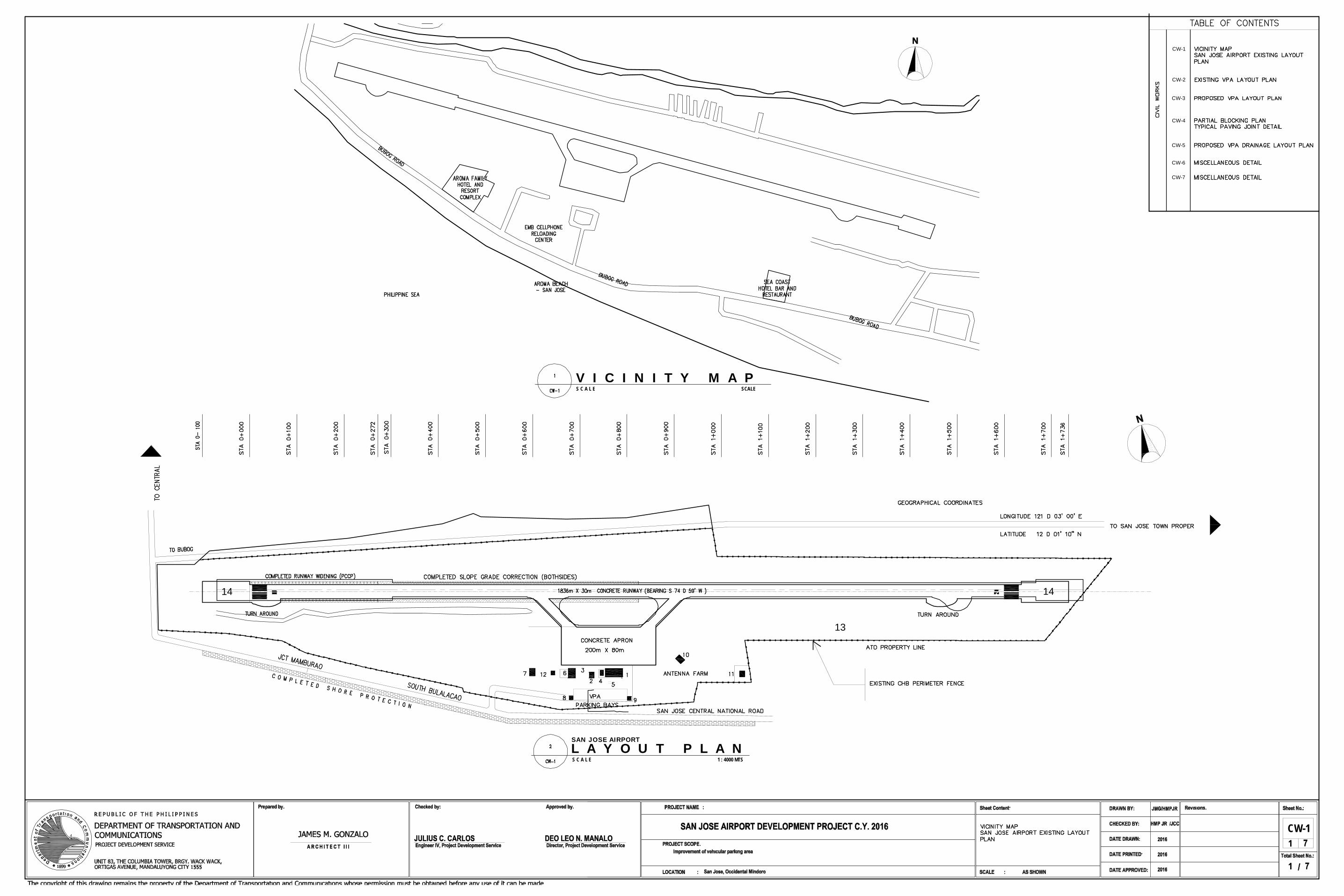
14 14
13
L A Y O U T P L A NS C A L E 1 : 4000 MTS
SAN JOSE AIRPORT
V I C I N I T Y M A PS C A L E SCALE
CW-11
1
CW-1
CW-2
CW-3
CW-4
CW-5
CW-6
CW-7

L A Y O U T P L A NS C A L E 1 : 250 MTS
EXISTING VEHICULAR PARKING AREA
PART OF EXISTING PTB
CW-22
2

L A Y O U T P L A NS C A L E 1 : 250 MTS
PROPOSED VEHICULAR PARKING AREA
PART OF EXISTING PTB
CW-33
3