Embed Size (px)
Citation preview
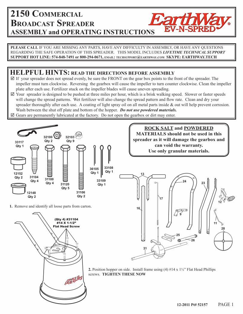
31104 Qty 4
32100 Qty 233117
Qty 1
36105 Qty 1
31100 Qty 4 31120
Qty 5
32103 Qty 9
31106 Qty 2
33108 Qty 1
33109 Qty 1
12152 Qty 2
12148 Qty 2
vvvvvvvv
vvvvvvvv
13
16
17
31
24
28
23
2526
9
11
121. Remove and identify all loose parts from carton.
(Qty 4) #31104#14 X 1-1/2”
Flat Head Screw
2. Position hopper on side. Install frame using (4) #14 x 1½” Flat Head Phillips screws. TIGHTEN THESE NOW
12-2011 Pt# 52157 PAGE 1
2150 CommerCialBroadCast spreaderASSEMBLY and OPERATING INSTRUCTIONS EV-N-SPREDEV-N-SPRED
EarthWayEarthWayRR
PLEASE CALL IF YOU ARE MISSING ANY PARTS, HAVE ANY DIFFICULTY IN ASSEMBLY, OR HAVE ANY QUESTIONS REGARDING THE SAFE OPERATION OF THIS SPREADER. THIS MODEL INCLUDES LIFETIME TECHNICAL SUPPORT SUPPORT HOT LINE: 574-848-7491 or 800-294-0671, email: [email protected] SKYPE: EARTHWAY.TECH
HELPFUL HINTS: READ THE DIRECTIONS BEFORE ASSEMBLY ; If your spreader does not spread evenly, be sure the FRONT on the gear box points to the front of the spreader. The impeller must turn clockwise. Reversing the gearbox will cause the impeller to turn counter clockwise. Clean the impeller plate after each use. Fertilizer stuck on the impeller blades will cause uneven spreading.
; Your spreader is designed to be pushed at three miles per hour, which is a brisk walking speed. Slower or faster speeds will change the spread patterns. Wet fertilizer will also change the spread pattern and flow rate. Clean and dry your spreader thoroughly after each use. A coating of light spray oil on all metal parts inside & out will help prevent corrosion. Wash between the shut off plate and bottom of the hopper. Do not use powdered materials.
; Gears are permanently lubricated at the factory. Do not open the gearbox or dirt may enter.
ROCK SALT and POWDERED MATERIALS should not be used in this
spreader as it will damage the gearbox and can void the warranty.
Use only granular materials.
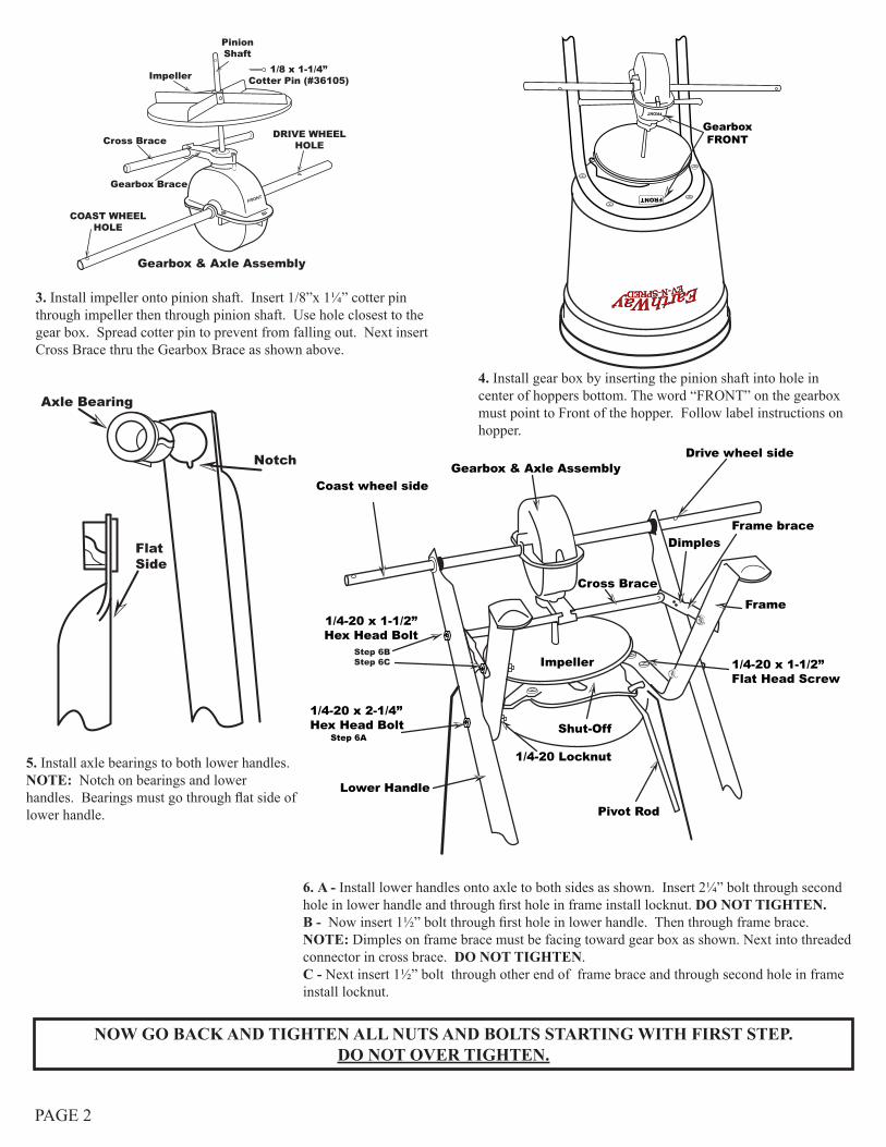
Gearbox & Axle AssemblyDrive wheel side
Coast wheel side
Frame brace
1/4-20 x 1-1/2”Hex Head Bolt
1/4-20 x 2-1/4”Hex Head Bolt
1/4-20 Locknut
Impeller
Cross Brace
Dimples
Frame
Lower Handle
Pivot Rod
Shut-Off
Step 6BStep 6C
Step 6A
1/4-20 x 1-1/2”Flat Head Screw
3. Install impeller onto pinion shaft. Insert 1/8”x 1¼” cotter pin through impeller then through pinion shaft. Use hole closest to the gear box. Spread cotter pin to prevent from falling out. Next insert Cross Brace thru the Gearbox Brace as shown above.
FRONT
PinionShaft
1/8 x 1-1/4”Cotter Pin (#36105)
DRIVE WHEELHOLE
COAST WHEELHOLE
Impeller
Cross Brace
Gearbox & Axle Assembly
Gearbox Brace
GearboxFRONT
FRONT
FRONT
4. Install gear box by inserting the pinion shaft into hole in center of hoppers bottom. The word “FRONT” on the gearbox must point to Front of the hopper. Follow label instructions on hopper.
Axle Bearing
FlatSide
Notch
5. Install axle bearings to both lower handles. NOTE: Notch on bearings and lower handles. Bearings must go through flat side of lower handle.
6. A - Install lower handles onto axle to both sides as shown. Insert 2¼” bolt through second hole in lower handle and through first hole in frame install locknut. DO NOT TIGHTEN. B - Now insert 1½” bolt through first hole in lower handle. Then through frame brace. NOTE: Dimples on frame brace must be facing toward gear box as shown. Next into threaded connector in cross brace. DO NOT TIGHTEN. C - Next insert 1½” bolt through other end of frame brace and through second hole in frame install locknut.
NOW GO BACK AND TIGHTEN ALL NUTS AND BOLTS STARTING WITH FIRST STEP. DO NOT OVER TIGHTEN.
PAGE 2
PAGE 3
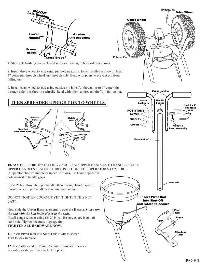
SLIDE
GearboxAxle Assembly
Lower Handle
Frame Brace
Cross Brace
Axle Bushing
7. Slide axle bushing over axle and into axle bearing to both sides as shown.
8. Install drive wheel to axle using pin hole nearest to lower handles as shown. Insert 2” cotter pin through wheel and through axle. Bend with pliers to prevent pin from falling out.
9. Install coast wheel to axle using outside pin hole. As shown, insert 1” cotter pin through axle (not thru the wheel). Bend with pliers to prevent pin from falling out.
2” Cotter Pin
1” Cotter Pin
Coast Wheel
Drive Wheel
10. NOTE: BEFORE INSTALLING GAUGE AND UPPER HANDLES TO HANDLE SHAFT, UPPER HANDLES FEATURE THREE POSITIONS FOR OPERATOR’S COMFORT. If operator chooses middle or upper positions, use handle spacer in hole nearest to handle grips.
Insert 2” bolt through upper handle, then through handle spacer through other upper handle and secure with locknut..DO NOT TIGHTEN LOCKNUT YET. TIGHTEN THIS NUT LAST.
Now slide the upper handle assembly over the handle shaft (on the end with the bolt holes closer to the end). Install gauge & lever using (2) 2” bolts. Be sure gauge is on left hand side. Tighten locknuts to gauge first. TIGHTEN ALL HARDWARE NOW.
11. Insert pivot rod into shut-off plate as shown. Turn to lock in place.
12. Insert other end of pivot rod into pivot and BraCket assembly as shown. Turn to lock in place.
TURN SPREADER UPRIGHT ON TO WHEELS.
Shut-OffPlate
Pivot Rodwith extra bend
RotatePivot
Angle
Attaching Arm
PivotRod
Insert Pivot Rodinto Shut-Off
and rotate to secure
1/4-20 x 2” Hex Head
Bolt
Gauge &Lever Assembly
HandleSpacer
Upper Handles
1/4-20Locknuts
POSITIONSLOWER
MIDDLE
UPPER
Handle Shaft
Long end
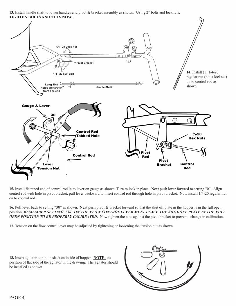
Control RodTabbed Hole
Control Rod
Lever Tension Nut
Gauge & Lever
30
1/4 - 20 Lock-nut
1/4 - 20 x 2” Bolt
Pivot Bracket
Long EndHoles are farther
from one endHandle Shaft
14. Install (1) 1/4-20 regular nut (not a locknut) on to control rod as shown.
15. Install flattened end of control rod in to lever on gauge as shown. Turn to lock in place. Next push lever forward to setting “0”. Align control rod with hole in pivot bracket, pull lever backward to insert control rod through hole in pivot bracket. Now install 1/4-20 regular nut on to control rod.
16. Pull lever back to setting “30” as shown. Next push pivot & bracket forward so that the shut off plate in the hopper is in the full open position. REMEMBER SETTING “30” ON THE FLOW CONTROL LEVER MUST PLACE THE SHUT-OFF PLATE IN THE FULL OPEN POSITION TO BE PROPERLY CALIBRATED. Now tighten the nuts against the pivot bracket to prevent change in calibration.
17. Tension on the flow control lever may be adjusted by tightening or loosening the tension nut as shown.
¼-20Hex Nuts
Pivot Bracket Control
Rod
PivotRod
18. Insert agitator to pinion shaft on inside of hopper. NOTE: the position of flat side of the agitator in the drawing. The agitator should be installed as shown.
PAGE 4
13. Install handle shaft to lower handles and pivot & bracket assembly as shown. Using 2” bolts and locknuts. TIGHTEN BOLTS AND NUTS NOW.
PAGE 5
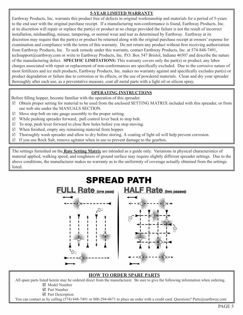
The settings furnished on the Rate Setting Matrix are intended as a guide only. Variations in physical characteristics of material applied, walking speed, and roughness of ground surface may require slightly different spreader settings. Due to the above conditions, the manufacturer makes no warranty as to the uniformity of coverage actually obtained from the settings listed.
HOW TO ORDER SPARE PARTSAll spare parts listed herein may be ordered direct from the manufacturer. Be sure to give the following information when ordering.
; Model Number ; Part Number ; Part Description
You can contact us by calling (574) 848-7491 or 800-294-0671 to place an order with a credit card. Questions? [email protected]
FULL Rate (one pass) HALF Rate (two passes)
SPREAD PATH
5-YEAR LIMITED WARRANTYEarthway Products, Inc. warrants this product free of defects in original workmanship and materials for a period of 5-years to the end user with the original purchase receipt. If a manufacturing non-conformance is found, Earthway Products, Inc. at its discretion will repair or replace the part(s) or product at no charge provided the failure is not the result of incorrect installation, mishandling, misuse, tampering, or normal wear and tear as determined by Earthway. Earthway at its discretion may require that the part(s) or product be returned along with the original purchase receipt at owners’ expense for examination and compliance with the terms of this warranty. Do not return any product without first receiving authorization from Earthway Products, Inc. To seek remedy under this warranty, contact Earthway Products, Inc. at 574-848-7491, [email protected] or write to Earthway Products, Inc. P.O. Box 547 Bristol, Indiana 46507 and describe the nature of the manufacturing defect. SPECIFIC LIMITATIONS: This warranty covers only the part(s) or product; any labor charges associated with repair or replacement of non-conformances are specifically excluded. Due to the corrosive nature of most fertilizers and ice melt products, Earthway Products, Inc. makes no warranty against and specifically excludes part(s) or product degradation or failure due to corrosion or its effects, or the use of powdered materials. Clean and dry your spreader thoroughly after each use, as a preventative measure, coat all metal parts with a light oil or silicon spray.
OPERATING INSTRUCTIONSBefore filling hopper, become familiar with the operation of this spreader.
5 Obtain proper setting for material to be used from the enclosed SETTING MATRIX included with this spreader, or from our web site under the MANUALS SECTION.
5 Move stop bolt on rate gauge assembly to the proper setting. 5 While pushing spreader forward, pull control lever back to stop bolt. 5 To stop, push lever forward to close flow holes before you stop moving. 5 When finished, empty any remaining material from hopper. 5 Thoroughly wash spreader and allow to dry before storing. A coating of light oil will help prevent corrosion. 5 If you use Rock Salt, remove agitator when in use to prevent damage to the gearbox.
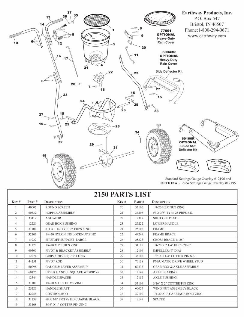
2150 PARTS LISTkey # part # desCription key # part # desCription
1 40002 ROUND SCREEN 20 32100 1/4-20 HEX NUT ZINC
2 60332 HOPPER ASSEMBLY 21 36208 #6 X 3/8" TYPE 25 PHPS S.S.
3 33117 AGITATOR 22 12317 SHUT OFF PLATE
4 12220 GEAR BOX BUSHING 23 25222 LOWER HANDLE
5 31104 #14 X 1 1/2 TYPE 25 FHPS ZINC 24 25106 FRAME
6 32103 1/4-20 NYLON INS LOCKNUT ZINC 25 44249 FRAME BRACE
7 11927 SHUTOFF SUPPORT- LARGE 26 25228 CROSS BRACE 11.25”
8 31120 1/4-20 X 2" HHCS ZINC 27 31106 1/4-20 X 2 1/4" HHCS ZINC
9 60300 PIVOT & BRACKET ASSEMBLY 28 12109 IMPELLER (9" DIA)
10 12274 GRIP (2150/2170) 7.5" LONG 29 36105 1/8" X 1 1/4" COTTER PIN S.S.
11 44251 PIVOT ROD 30 70138 PNEUMATIC DRIVE WHEEL STUD
12 60298 GAUGE & LEVER ASSEMBLY 31 60333 GEAR BOX & AXLE ASSEMBLY
13 60175 UPPER HANDLE SQUARE W/GRIP ea 32 12148 AXLE BEARING
14 12344 HANDLE SPACER 33 12152 AXLE BUSHING
15 31100 1/4-20 X 1 1/2 HHMS ZINC 34 33109 3/16" X 2" COTTER PIN ZINC16 25223 HANDLE SHAFT 35 60027 WING NUT ASSEMBLY BLACK
17 42256 CONTROL ROD 36 37100 1/4-20 X 1" CARRIAGE BOLT ZINC
18 31138 #8 X 3/8" PMT #8 HD COARSE BLACK 37 12147 SPACER
19 33108 3/16" X 1" COTTER PIN ZINC
23
10
24
7
22
28
21
9
11
20
6
2
3
1
19
30
3132
33
34
29
23
2526
8
5
8
6
6
17
20
27
15 25
15
13 353637
14
16
15
27
12
4
1815
60043ROPTIONALHeavy-Duty Rain Cover
& Side Deflector Kit
77001OPTIONALHeavy-DutyRain Cover
60166ROPTIONAL3-Side Salt Deflector Kit
Earthway Products, Inc.P.O. Box 547
Bristol, IN 46507Phone:1-800-294-0671
www.earthway.com
30 20 10 0
Lesco Settings
Standard Settings Gauge Overlay #12196 andOPTIONAL Lesco Settings Gauge Overlay #12195
30 20 10 0
EarthWay Settings