Embed Size (px)
Citation preview

Series PA3000/5000Process Pump
Automatically Operated Type (Internal Switching Type)/Air Operated Type (External Switching Type)
Automaticallyoperated type
Switching valve Air supply port
Air exhaust port
Discharge port
Suction port
Compatible with a wide variety of fluids • PA3000: Max. discharge rate 20 l/min • PA5000: Max. discharge rate 45 l/min
Air operated type
5 port solenoid valves
Air supply port
Discharge port
Suction port
Transferring liquid by suction Transferring liquid by pressureAtomizing liquid Stirring liquid
• Prevents sticking of liquids
Application Example
Control with external switching valve makes constant cycling possible • Easily control the discharge rate. Easily adjust the flow with the external solenoid valve's ON/OFF cycle. • Easy to operate, even for minute flow, low press operation or operation involving air. • Can be used for operation with repetitive stopping.
669
High abrasion resistance and low particle generationNo sliding parts in wetted areas.
Self-priming makes priming unnecessaryExhausts the air inside the suction pipe to suck up liquid.
PA
PAP
PAX
PB
PAFPA�PB
212-PA.qxd 10.7.16 11:42 AM Page 1
Courtesy of Steven Engineering, Inc.-230 Ryan Way, South San Francisco, CA 94080-6370-Main Office: (650) 588-9200-Outside Local Area: (800) 258-9200-www.stevenengineering.com

Specifications
0Option
Automatically operated type
Air operated type
PA3000
JIS Symbol
Symbol03
Port sizePort size
3/8"
SymbolNilNFT
TypeRc
NPTG
NPTF
Thread type
Symbol
12
Diaphragm material
Diaphragmmaterial
PTFENBR
Automaticallyoperated
�
�
Applicable actuation
Air operated
�
—
Actuation
Symbol12
Material of body wetted areasMaterial of body wetted areas
ADC12 (Aluminum)SCS14 (Stainless steel)
Model PA3110Automatically operated
1 to 20 l/min
0 to 0.6 MPa
0.2 to 0.7 MPa
Max. 200 l/min (ANR) or less
80 dB (A) or less(Option: with silencer, AN200)
1.05 MPa
—
—
Air operated
PTFE
0.1 to 12 l/min
0 to 0.4 MPa
0.1 to 0.5 MPa
Max. 150 l/min (ANR) or less
0.75 MPa
50 million times
0.20
Rc, NPT, G, NPTF 3/8" Female thread
Rc, NPT, G, NPTF 1/4" Female thread
PTFE, PFA
1 m (Interior of pump dry)
Up to 6 m (liquid inside pump)
0 to 60°C (No freezing)
0 to 60°C (No freezing)
Horizontal (with mounting foot at bottom)
General environment
PA3120 PA3210 PA3220 PA3113Actuation
Port size
Material
Discharge rate
Average discharge pressure
Pilot air pressure
Air consumption
Note 1)
Noise
Withstand pressure
Diaphragm life
Fluid temperature
Ambient temperature
Recommended operating cycle
Pilot air solenoid valve recommended Cv factor
Mass
Mounting orientation
Packaging
Main fluid suction discharge port
Pilot air supply/exhaust port
Body wetted areas
Diaphragm
Check valve
Dry
Wet
PTFE
ADC12
NBR NBRPTFE
SCS14 ADC12 SCS14
1.7 kg 2.2 kg 1.7 kg 2.2 kg
100 million times 50 million times 50 million times100 million times
PA3213
FLUID OUTAIR SUP
AIR EXH FLUID IN
1 13PA 03
FLUID OUTP1P2
FLUID IN
Made to order specifications(For details, refer to pages 724 to 726)
Products complying with ATEX
With air operated reset port Note)
With operating cycle counting port Note)
Note) For automatically operated type only.
∗ Each of the values above are for normal temperatures and when the transferred fluid is fresh water.∗ Refer to page 727 for maintenance parts.∗ For related products, refer to page 728 and 729.Note 1) With cycles at 2 Hz or moreNote 2) After initial suction of liquid operating at 1 to 7 Hz, it can be used with operation at lower cycles.
Since a large quantity of liquid will be pumped out, use a suitable throttle in the discharge port if problems occur.
Note 3) With a low number of operating cycles, even a valve with a small Cv factor can be operated.
Symbol03
ActuationAutomatically operated
Air operated
Process PumpAutomatically Operated Type (Internal Switching Type)
Air Operated Type (External Switching Type)
Series PA3000
Made toOrder
Suction lifting range
Symbol
NilN
Option
Body onlyWith silencer
Automaticallyoperated
�
�
Applicable actuation
Airoperated
�
—
1 to 7 Hz (0.2 to 1 Hz also possible depending on conditions) Note 2)
72 dB (A) or less (excluding the noise from the
quick exhaust and solenoid valve)
Note 3)
How to Order
670Courtesy of Steven Engineering, Inc.-230 Ryan Way, South San Francisco, CA 94080-6370-Main Office: (650) 588-9200-Outside Local Area: (800) 258-9200-www.stevenengineering.com

Specifications
Automatically operated type
Air operated type
JIS Symbol
FLUID OUTAIR SUP
AIR EXH FLUID IN
FLUID OUTP1P2
FLUID IN
PA5000
Symbol0406
Port sizePort size
1/2"3/4"
Thread type
Diaphragm material
Material of body wetted areas
Model PA5110Automatically operated
5 to 45 l/min
0 to 0.6 MPa
0.2 to 0.7 MPa
Max. 300 l/min (ANR) or less
Up to 2 m(Interior of pump dry)
78 dB (A) or less(Option: with silencer, AN 200)
1.05 MPa
—
—
Air operated
PTFE
1 to 24 l/min
0 to 0.4 MPa
0.1 to 0.5 MPa
Max. 250 l/min (ANR) or less
Up to 0.5 m(Interior of pump dry)
0.75 MPa
0.45
Rc, NPT, G, NPTF 1/2", 3/4" Female thread
Rc, NPT, G, NPTF 1/4" Female thread
PTFE, PFA
Up to 6 m (Liquid inside pump)
50 million times
0 to 60°C (No freezing)
0 to 60°C (No freezing)
Horizontal (with mounting foot at bottom)
General environment
1 to 7 Hz (0.2 to 1 Hz also possible depending on conditions) Note 2)
72 dB (A) or less (excluding the noise from the
quick exhaust and solenoid valve)
PA5120 PA5210 PA5220 PA5113Actuation
Port size
Material
Discharge rate
Average discharge pressure
Pilot air pressure
Air consumption
Note 1)
Noise
Withstand pressure
Diaphragm life
Operating fluid temperature
Ambient temperature
Recommended operating cycle
Pilot air solenoid valve recommended Cv factor
Mass
Mounting orientation
Packaging
Main fluid suction discharge port
Pilot air supply/exhaust port
Body wetted areas
Diaphragm
Check valve
Dry
Wet
PTFE
ADC12
NBR NBRPTFE
SCS14 ADC12 SCS14
3.5 kg 6.5 kg 3.5 kg 6.5 kg
PA5213
How to Order
011PA 5 04
∗ Each of the values above are for normal temperatures and when the transferred fluid is fresh water.∗ Refer to page 727 for maintenance parts.∗ For related products, refer to page 728 and 729.Note 1) With cycles at 2 Hz or moreNote 2) After initial suction of liquid operating at 1 to 7 Hz, it can be used with operation at lower cycles.
Since a large quantity of liquid will be pumped out, use a suitable throttle in the discharge port if problems occur.
Note 3) With a low number of operating cycles, even a valve with a small Cv factor can be operated.
Process PumpAutomatically Operated Type (Internal Switching Type)
Air Operated Type (External Switching Type)
Series PA5000
Symbol12
Material of body wetted areasADC12 (Aluminum)
SCS14 (Stainless steel)
Suction lifting range
Symbol
12
Diaphragmmaterial
PTFENBR
Automaticallyoperated
�
�
Applicable actuation
Air operated
�
—
Symbol03
ActuationAutomatically operated
Air operated
SymbolNilNFT
TypeRc
NPTG
NPTF
Actuation
Option
Symbol
NilN
Option
Body onlyWith silencer
Automaticallyoperated
�
�
Applicable actuation
Airoperated
�
—
Made to order specifications(For details, refer to pages 724 to 726)
Products complying with ATEX
With air operated reset port Note)
With operating cycle counting port Note)
Note) For automatically operated type only.
Made toOrder
Note 3)
671
PA
PAP
PAX
PB
PAFPA�PB
Courtesy of Steven Engineering, Inc.-230 Ryan Way, South San Francisco, CA 94080-6370-Main Office: (650) 588-9200-Outside Local Area: (800) 258-9200-www.stevenengineering.com

Performance Curve: Automatically Operated Type
Required specifications example:Find the pilot air pressure and pilot air consumption for a discharge rate of 6 l/min and a discharge pressure of 0.25 MPa. <The transfer fluid is fresh water (viscosity 1 mPa·s, specific gravity 1.0).>∗ If the total lifting height is required instead of the discharge pressure, a discharge pressure of 0.1 MPa corresponds to a total lift of 10 m.
Selection procedures:1. First mark the intersection point for a discharge rate of 6 l/min and a discharge pressure of 0.25 MPa.2. Find the pilot air pressure for the marked point. In this case, the point is between the discharge curves (solid lines) for SUP = 0.2 MPa and
SUP = 0.5 MPa, and based on the proportional relationship to these lines, the pilot air pressure for this point is approximately 0.38 MPa.3. Next find the air consumption rate. Since the marked point is below the curve for 50 l/min (ANR), the maximum rate will be about 50
l/min (ANR).
Required specifications example:Find the pilot air pressure and pilot air consumption for a dis-charge rate of 2.7 l/min, and a viscosity of 100 mPa·s.Selection procedures:1. First find the ratio of the discharge rate for fresh water when
viscosity is 100 mPa·s from the graph below. It is determined to be 45%.
2. Next, in the required specification example, the viscosity is 100 mPa·s and the discharge rate is 2.7 l/min. Since this is equivalent to 45% of the discharge rate for fresh water, 2.7 l/min ÷ 0.45 = 6 l/min, indicating that a discharge rate of 6 l/min is required for fresh water.
3. Finally, find the pilot air pressure and pilot air consumption based on selection from the flow characteristic graphs.
Selection from Flow Characteristic Graph (PA3��0)
Selection from Viscosity Characteristic GraphViscosity Characteristics (Flow rate correction for viscous fluids)
Caution1. These flow characteristics are for fresh water (viscosity 1 mPa·s, specific gravity 1.0).2. The discharge rate differs greatly depending on properties (viscosity, specific gravity) of the fluid being
transferred and operating conditions (lifting range, transfer distance), etc.3. Use 0.75 kW per 100 l/min of air consumption as a guide for the relationship of the air consumption to the
compressor.
CautionViscosities up to 1000 mPa·s can be used.Dynamic viscosity ν = Viscosity µ/Density ρ.
ν =
ν(10–3 m2/s) = µ(mPa·s)/ρ(kg/m3)
PA3��0 Flow Characteristics PA5��0 Flow Characteristics
0.6
0.5
0.4
0.3
0.2
0.1
0
Discharge rate (l/min)
Dis
char
ge p
ress
ure
(MP
a)
SUP = 0.7 MPa
SUP = 0.5 MPa
SUP = 0.2 MPa
Air consumption 100 l/m
in (ANR)
Air consumption 50 l/min (ANR)
SUP = 0.7 MPa
SUP = 0.5 MPa
SUP = 0.2 MPa
Air consumption 200 l/m
in (ANR)
Air consumption 100 l/m
in (ANR)
10 20
0.6
0.5
0.4
0.3
0.2
0.1
0
Discharge rate (l/min)D
isch
arge
pre
ssur
e (M
Pa)
10 30 40 5020 60
100
50
01 10 100 1000
Viscosity (mPa·s)
Rat
io o
f dis
char
ge r
ate
agai
nst f
resh
wat
er (
%)
µρ
672
Series PA
Courtesy of Steven Engineering, Inc.-230 Ryan Way, South San Francisco, CA 94080-6370-Main Office: (650) 588-9200-Outside Local Area: (800) 258-9200-www.stevenengineering.com

Performance Curve: Air Operated Type
Required specification example: Find the pilot air pressure and pilot air consumption for a discharge rate of 6 l/min. <The transfer fluid is fresh water (viscosity 1 mPa·s, specific gravity 1.0).>Note 1) If the total lifting height is required instead of the discharge pressure, a dis-
charge pressure of 0.1 MPa corresponds to a total lift of 10 m.Selection procedures:1. First mark the intersection point for a discharge rate of 6 l/min and a dis-
charge pressure of 0.1 MPa.2. Find the pilot air pressure for the marked point. In this case, the point is
between the discharge curves (solid lines) for SUP = 0.2 MPa and SUP = 0.3 MPa, and based on the proportional relationship to these lines, the pilot air pressure for this point is approximately 0.25 MPa.
Required specification example: Find the pilot air pressure and pilot air consumption for a discharge rate of 2.7 l/min, and a viscosity of 100 mPa·s.
Selection procedures:1. First find the ratio of the discharge rate for fresh water when viscosity is 100
mPa·s from the graph below. It is determined to be 45%.2. Next, in the required specification example, the viscosity is 100m Pa·s and
the discharge rate is 2.7 l/min. Since this is equivalent to 45% of the discharge rate for fresh water, 2.7 l/min ÷ 0.45 = 6 l/min, indicating that a discharge rate of 6 l /min is required for fresh water.
3. Finally, find the pilot air pressure and pilot air consumption based on selection from the flow characteristic graphs.
Selection from Flow Characteristic Graph (PA3�13)
Selection from Viscosity Characteristic Graph
Caution
PA3�13 Flow Characteristics
PA3�13 Air Consumption
PA5�13 Air Consumption
PA5�13 Flow Characteristics
0
Find the air consumption for operation with a 4 Hz switching cycle and pilot air pressure of 0.3 MPa from the air consumption graph.Selection procedures:1. Look up from the 4 Hz switching cycle to find the intersection with SUP = 0.3 MPa.2. From the point just found, draw a line to the Y-axis to find the air
consumption. The result is approximately 50 l/min (ANR).
Calculating Air Consumption (PA3�13)
Caution1. These flow characteristics are for fresh water (viscosity 1 mPa·s,
specific gravity 1.0).2. The discharge rate differs greatly depending on properties (viscosity,
specific gravity) of the fluid being transferred and operating conditions (density, lifting range, transfer distance).
SUP = 0.5 MPa
SUP = 0.3 MPa
SUP = 0.2 MPa
2 3 4 5 6 7
20
40
60
80
100
120
140
160
10
Cycle (Hz)
Air
cons
umpt
ion
(l/m
in [A
NR
])
Cycle (Hz)
Air
cons
umpt
ion
(l/m
in [A
NR
])
Viscosity Characteristics (Flow rate correction for viscous fluids)
100
50
01 10 100 1000
Viscosity (mPa·s)
Rat
io o
f dis
char
ge r
ate
agai
nst f
resh
wat
er (
%)
Viscosities up to 1000 mPa·s can be used.Dynamic viscosity ν = Viscosity µ/Density ρ.ν =
ν(10–3 m2/s) = µ(mPa·s)/ρ(kg/m3)
µρ
0.5
0.4
0.3
0.2
0.1
0
Dis
char
ge p
ress
ure
(MP
a)
2 4 6 8 10 12
SUP = 0.4 MPa
SUP = 0.2 MPa
SUP = 0.3 MPa
Discharge rate (l/min)
SUP = 0.5 MPaCycle 7 HzCycle 5 HzCycle 3 Hz
5 10 15 20 25
Discharge rate (l/min)
0.1
0.2
0.3
0.4
0.5
Dis
char
ge p
ress
ure
(MP
a)
SUP = 0.2 MPa
SUP = 0.3 MPa
SUP = 0.5 MPa
SUP = 0.4 MPa
Cycle 5 HzCycle 3 HzCycle 1 Hz
0
50
100
150
200
250
300
1 32 54 76
SUP = 0.5 MPa
SUP = 0.3 MPaSUP = 0.4 MPa
SUP = 0.2 MPa
673
Series PAProcess PumpAutomatically Operated Type
PA
PAP
PAX
PB
PAFPA�PB
Courtesy of Steven Engineering, Inc.-230 Ryan Way, South San Francisco, CA 94080-6370-Main Office: (650) 588-9200-Outside Local Area: (800) 258-9200-www.stevenengineering.com

Automatically Operated Type
1. When air is supplied, it passes through the switching valve and enters drive chamber B.2. Diaphragm B moves to the right, and at the same time diaphragm A also moves to the right pushing pilot valve A. 3. When pilot valve A is pushed, air acts upon the switching valve, drive chamber A switches to a supply state, and the air which was in
drive chamber B is exhausted to the outside.4. When air enters drive chamber A, diaphragm B moves to the left pushing pilot valve B. 5. When pilot valve B is pushed, the air which was acting upon the switching valve is exhausted, and drive chamber B once again
switches to a supply state. A continuous reciprocal motion is generated by this repetition.
1. When air enters drive chamber B, the fluid in pump chamber B is forced out, and at the same time fluid is sucked into pump chamber A. 2. When the diaphragm moves in the opposite direction, the fluid in pump chamber A is forced out, and fluid is sucked into pump chamber B. 3. Continuous suction and discharge is performed by the reciprocal motion of the diaphragm.
Drive unit
Control unit
Pilot valve A Pilot valve B
Diaphragm BDiaphragm A Drive chamber A Drive chamber B
Check valve Shaft
Pump chamber BPump chamber A
Discharge port(FLUID OUT)
Suction port(FLUID IN)
Switching valve Air supply port (AIR SUP)
Air Operated Type
1. When air is supplied to P1 port, it enters drive chamber A.2. Diaphragm A moves to the left, and at the same time diaphragm B also moves to the left. 3. The fluid in pump chamber A is forced out to the discharge port, and the fluid is sucked into pump chamber B from the suction port.4. If air is supplied to the P2 port, the opposite will occur. Continuous suction and discharge of fluid is performed by repeating this process
with the control of an external solenoid valve (5 port valve).
5 port solenoid valves
P1 P2
Diaphragm BDiaphragm ADrive chamber A Drive chamber B
ShaftCheck valve
Pump chamber BPump chamber A
Air supply port(AIR SUP)
Discharge port(FLUID OUT)
Suction port(FLUID IN)
Working Principle
Air exhaust port(AIR EXH)
Dri
ve u
nit
Con
trol
uni
tD
rive
un
itEx
terna
l sole
noid
valve
674
Series PA
Courtesy of Steven Engineering, Inc.-230 Ryan Way, South San Francisco, CA 94080-6370-Main Office: (650) 588-9200-Outside Local Area: (800) 258-9200-www.stevenengineering.com

Mounting posture of the pump is set with the mounting bracket facing downward. Air to be supplied to the air supply port <AIR SUP> should be cleaned and filtered through AF filter, etc. Air with foreign matter or drainage etc. will have negative effects on the built-in sol-enoid valve and will lead to malfunction. When air needs additional purification, use a filter (Series AF), and a mist separator (Series AM) together.Maintain the proper tightening torque for fittings and mounting bolts, etc. Looseness can cause problems such as fluid and air leaks, while over tightening can cause damage to threads and parts, etc.
<Starting and Stopping> Refer to circuit example (1)1. Connect air piping to the air supply port <AIR SUP> and connect piping for the fluid to be transfered to the suction port <FLUID IN>
and the discharge port <FLUID OUT>. 2. Using a regulator, set the pilot air pressure within the range of 0.2 to 0.7 MPa. Then, the pump operates when power is applied to the 3
port solenoid valve of the air supply port <AIR SUP>, the sound of exhaust begins from the air exhaust port <AIR EXH> and fluid flows from the suction port <FLUID IN> to the discharge port <FLUID OUT>. At this time, the ball valve on the discharge side is in an open state. The pump performs suction with its own power even without pri-ming. (Dry state suction lifting range: max. 1 m) To restrict exhaust noise, attach a silencer (AN200-02: option) to the air exhaust port <AIR EXH>.
3. To stop the pump, exhaust the air pressure being supplied to the pump by the 3 port solenoid valve of the air supply port <AIR SUP>. The pump will also stop if the ball valve on the discharge side is closed.
<Discharge Flow Rate Adjustment>1. Adjustment of the flow rate from the discharge port <FLUID OUT> is performed with the ball valve connected on the discharge side or
the throttle connected on the air exhaust side. For adjustment from the air side, use of the silencer with throttle ASN2 (port size 1/4) connected to the air exhaust port <AIR EXH> is effective. Refer to circuit example (1).
2. When operating with a discharge flow rate below the specification range, provide a by-pass circuit from the discharge side to the suc-tion side to ensure the minimum flow rate inside the process pump. With a discharge flow rate below the minimum flow rate, the pro-cess pump may stop due to unstable operation. Refer to circuit example (2). (Minimum flow rates: PA3000 1 l/min, PA5000 5 l/min)
<Reset Button>When the pump stops during operation, press the reset button. This makes it possible to restore operation in case the switching valve be-comes clogged due to foreign matter in the supply air.
Operation
Circuit example (1)
Air filter Ball valveProcess Pump
Process Pump
BypassStrainer
Silencer Throttle Transfer fluid
AIRSUP
AIREXH
FLUIDOUT
FLUIDINAir supply
Regulator
3 portsolenoid valve
Circuit example (2)
Piping diagram
Discharge portFLUID OUT
Pilot air supply portAIR SUP
SilencerOption
Pilot air exhaust portAIR EXH
Suction portFLUID IN
Caution
Piping and Operation: Automatically Operated Type
Reset button
For related products, refer to page 728 and 729.
675
Series PAProcess PumpAutomatically Operated Type
PA
PAP
PAX
PB
PAFPA�PB
Courtesy of Steven Engineering, Inc.-230 Ryan Way, South San Francisco, CA 94080-6370-Main Office: (650) 588-9200-Outside Local Area: (800) 258-9200-www.stevenengineering.com

Piping and Operation: Air Operated Type
<Starting and Stopping> Refer to circuit example1. Connect air piping Note 1) to the pilot air supply port <P1>, <P2> and connect piping for the fluid to be transfered to the suction port
<FLUID IN> and the discharge port <FLUID OUT>. 2. Using a regulator, set the pilot air pressure within the range of 0.1 to 0.5 MPa. Then, the pump operates when power is applied to the
solenoid valve Note 2) of the pilot air supply port and fluid flows from the suction port <FLUID IN> to the discharge port <FLUID OUT>. At this time, the ball valve on the discharge side is in an open state. The pump performs suction with its own power even without priming. (Dry state suction lifting range: PA3 1 m, PA5 up to 0.5 m Note 3)) To restrict exhaust noise, attach a silencer to the solenoid valve air ex-haust port.
3. To stop the pump, exhaust the air pressure being supplied to the pump with the solenoid valve of the air supply port. Note 1) When used for highly permeable fluids, the solenoid valve may malfunction due to the gas contained in the exhaust. Implement
measures to keep the exhaust from going to the solenoid valve side.Note 2) For the solenoid valve, use an exhaust center 5 port valve, or a combination of residual exhaust 3 port valve and a pump drive 4
port valve. If air in the drive chamber is not released when the pump is stopped, the diaphragm will be subjected to pressure and its life will be shortened.
Note 3) When the pump is dry, operate the solenoid valve at a switching cycle of 1 to 7 Hz. If operated outside of this range, the suction lifting height may not reach the prescribed value.
<Discharge Flow Rate Adjustment>1. The flow rate from the discharge port <FLUID OUT> can be adjusted easily by changing the switching cycle of the solenoid valve on
the air supply port.
Circuit example (1)
Air filter Ball valveProcess Pump Process Pump
Strainer Strainer
Transfer fluid Transfer fluid
P1
P2
P1
P2
FLUIDOUT
FLUIDIN
FLUIDOUT
FLUIDIN
Air supply
Air supply
Regulator Air filter Regulator
5 portsolenoid valve
(Exhaust center)3 port
solenoidvalve
4 portsolenoid
valve
Circuit example (2)
Discharge portFLUID OUT
Suction portFLUID IN
Maintain the proper tightening torque for fittings and mounting bolts, etc. Looseness can cause problems such as fluid and air leaks, while over tightening can cause damage to threads and parts, etc.
Caution
Recommended Valve
PA3�13PA5�13
VQZ14�0 (Exhaust center)
VQZ24�0 (Exhaust center)
For related products, refer to page 728 and 729.
Piping diagram
Operation
Pilot air supply port: P1AIR SUP
Solenoid valve
Pilot air supply port: P2AIR SUP
676
Series PA
212-PA.qxd 10.7.16 11:42 AM Page 2
Courtesy of Steven Engineering, Inc.-230 Ryan Way, South San Francisco, CA 94080-6370-Main Office: (650) 588-9200-Outside Local Area: (800) 258-9200-www.stevenengineering.com

Dimensions
PA3��0/Automatically Operated Type
PA3�13/Air Operated Type
AIRSUP
AIREXH
FLUID OUT
FLUID I N
5.5
(185)
1054 x ø7
Silencer: AN200-02(Option)
7.5
Reset button
AIR SUP (Pilot air supply port) Rc, NPT, G, NPTF 1/4"
Rc, NPT, G, NPTF 1/4"
AIR EXH (Pilot air exhaust port)
2
100 130
3
FLUID INRc, NPT, G, NPTF 3/8"
FLUID OUTRc, NPT, G, NPTF 3/8"
44.5
74.5
115
68 85
90
32
PROCESSPUMP
FLUID OUT
FLUID I N
1054 x ø7 7.5
130
3
FLUID INRc, NPT, G, NPTF 3/8"
FLUID OUTRc, NPT, G, NPTF 3/8"
68 85
90
32
PROCESSPUMP
5.5
AIR SUP(P1)Rc, NPT, G, NPTF 1/4"
Rc, NPT, G, NPTF 1/4" AIR SUP(P2)
2
100
44.5
74.5
115P1
P2
677
Series PAProcess PumpAutomatically Operated Type
PA
PAP
PAX
PB
PAFPA�PB
212-PA.qxd 10.7.16 11:42 AM Page 3
Courtesy of Steven Engineering, Inc.-230 Ryan Way, South San Francisco, CA 94080-6370-Main Office: (650) 588-9200-Outside Local Area: (800) 258-9200-www.stevenengineering.com

PA5��0/Automatically Operated Type
PA5�13/Air Operated Type
FLUIDOUT
RESET
FLUIDI N
PROCESSPUMP
179 4 x ø9
90 90
56 165 56
112
202 1143.53
58.5
103.
5
125.
5
167
48.5
132.
5
AIR SUP(P1) Rc, NPT, G, NPTF 1/4"
P1
P2
FLUID INRc, NPT, G, NPTF 1/2", 3/4"
FLUID OUTRc, NPT, G, NPTF 1/2", 3/4"
Rc, NPT, G, NPTF 1/4" AIR SUP(P2)
FLUIDOUT
AIRSUP
RESET
AIREXH
FLUIDI N
PROCESSPUMP
179 4 x ø9
(257)
90 90
56 165 56
112
202 1143.53
58.5
103.
5
125.
5
167
48.5
132.
5
AIR SUP (Pilot air supply port)
Rc, NPT, G, NPTF 1/4"
Reset button
FLUID INRc, NPT, G, NPTF 1/2", 3/4"
FLUID OUTRc, NPT, G, NPTF 1/2", 3/4"
Rc, NPT, G, NPTF 1/4"
AIR EXH (Pilot air exhaust port)
Dimensions
Silencer: AN200-02(Option)
678
Series PA
Courtesy of Steven Engineering, Inc.-230 Ryan Way, South San Francisco, CA 94080-6370-Main Office: (650) 588-9200-Outside Local Area: (800) 258-9200-www.stevenengineering.com

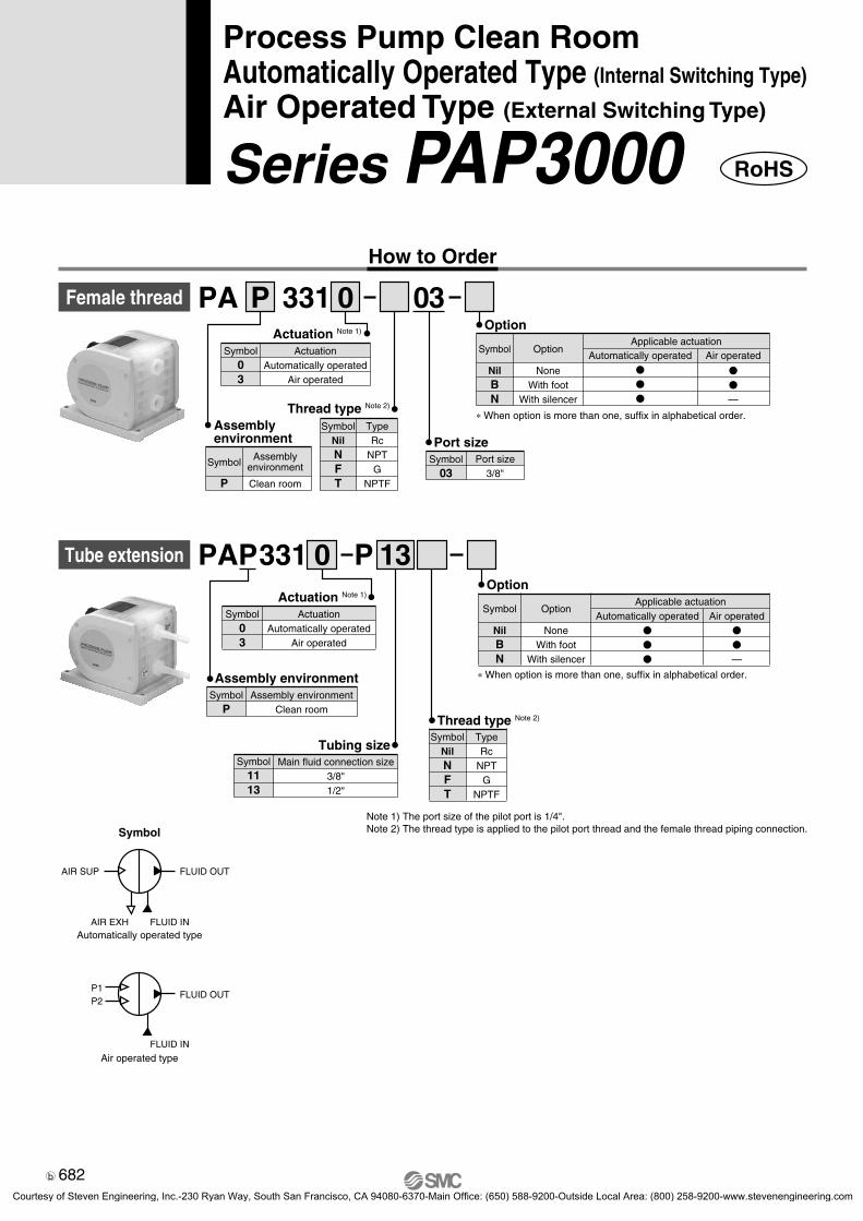
Series PAP3000Process Pump
Fluororesin Type
Body material made from New PFA
for superior corrosion resistance.New PFA
679
PA
PAP
PAX
PB
PAFPA�PB
Courtesy of Steven Engineering, Inc.-230 Ryan Way, South San Francisco, CA 94080-6370-Main Office: (650) 588-9200-Outside Local Area: (800) 258-9200-www.stevenengineering.com

Model Bodymaterial
New PFA PTFE
Diaphragmmaterial
Assemblyenvironment
Standard
Clean room
Standard
Clean room
1 to 13∗
0.1 to 9
•Foot•Silencer
•Foot
OptionDischarge rate
(l/min)
Automaticallyoperated type
Air pilotoperated type
PA3310PAP3310PA3313PAP3313
Variations
Resin coversPP
FootPP
Through boltsSS
Side bodiesNew PFA
DiaphragmsPTFE
Center platePPS
∗With 3/8" inlet/outlet tube:1 to 12
With the use of New New PFA for body material,With the use of New PFA for body material,
PortsNew PFA
FLUIDOUT
FLUIDIN
DiaphragmmaterialPTFE
DiaphragmmaterialPTFEBody material
New PFABody materialNew PFA
680
high corrosion resistance is achieved!
5-way valveAir supply port
Discharge port
Suction port
Air pilot actuation reset is now a standard feature.When the pump is used in an environment where manual reset is not possible, designing a circuit as the one shown below allows the use of air pressure for reset purposes.With the use of an air pilot actuation reset circuit, resetting can be done by releasing the air pressure after supplying it to the reset port.
high corrosion resistance is achieved!
CleanYou can order your process pump assembled in a
Clean room environment and double-packaged
(Order number PAP331�).
Side bodies and ports are molded to achieve a
great reduction in dust generation.
External switching valve control makes constant cycling possible.• Discharge rate is easily controlled.
The flow rate can be easily adjusted by the number of ON/OFF cycles of the external solenoid valve.
• Stable operation is possible in spite of such conditions as a minimal flow rate, low pressure operation, or the entrainment of gasses.
• Can be used for operation with repetitive stopping.
Air pilot actuation is standard.
Air pilot actuation reset circuit
RegulatorProcess
pump Ballvalve
Airfilter
Strainer
AIR SUP
AIR EXHFLUID IN
FLUID OUT
Compact & Light weight (Without foot)
110
mm
138 mm120 mm
Reset button
Mass: 2.1 kg
681
PA
PAP
PAX
PB
PAFPA�PB
Courtesy of Steven Engineering, Inc.-230 Ryan Way, South San Francisco, CA 94080-6370-Main Office: (650) 588-9200-Outside Local Area: (800) 258-9200-www.stevenengineering.com
Symbol
Automatically operated type
FLUID OUTAIR SUP
AIR EXH FLUID IN
Air operated type
FLUID OUTP1P2
FLUID IN
Female thread 0331PA 03
SymbolNilNFT
TypeRc
NPTG
NPTF
P
Note 1) The port size of the pilot port is 1/4". Note 2) The thread type is applied to the pilot port thread and the female thread piping connection.
Assembly environment
Symbol
P
Assemblyenvironment
Clean room
Symbol03
Actuation Note 1)
ActuationAutomatically operated
Air operated
Thread type Note 2)
Symbol03
Port sizePort size
3/8"
Symbol
NilBN
Option
Option
NoneWith foot
With silencer
Applicable actuationAutomatically operated
�
�
�
Air operated
�
�
—
∗ When option is more than one, suffix in alphabetical order.
Assembly environment
Tube extension 0PAP331Actuation Note 1)
Symbol03
ActuationAutomatically operated
Air operated
Symbol
NilBN
Option
Option
NoneWith foot
With silencer
Applicable actuationAutomatically operated
�
�
�
Air operated�
�
—
P
SymbolNilNFT
Thread type Note 2)
TypeRc
NPTG
NPTF
13
∗ When option is more than one, suffix in alphabetical order.
Symbol1113
Tubing sizeMain fluid connection size
3/8"1/2"
SymbolP
Assembly environmentClean room
682
Process Pump Clean RoomAutomatically Operated Type (Internal Switching Type)
Air Operated Type (External Switching Type)
Series PAP3000How to Order
RoHS
RoHS-PAP.qxd 10.7.29 0:01 PM Page 1
Courtesy of Steven Engineering, Inc.-230 Ryan Way, South San Francisco, CA 94080-6370-Main Office: (650) 588-9200-Outside Local Area: (800) 258-9200-www.stevenengineering.com

Symbol
NilBN
Option
Option
NoneWith foot
With silencer
Applicable actuation
Automaticallyoperated
�
�
�
Air operated
�
�
—
∗ When option is more than one, suffix in alphabetical order.
Symbol
111113131113
1319191319
Fitting size
Fitting type
IN side
3344455
OUT side
3434545
Symbol12
Fitting typeLQ1LQ2
With nut S S 130 1
Integral fitting type
PAP331
PAP331 S 130
Symbol1113
Fitting sizeFitting sizeLQ2 3/8"LQ2 1/2"
Note 1) The port size of the pilot port is 1/4". Note 2) The thread type is applied to the pilot port thread and the female
thread piping connection.Note 3) Refer to the pamphlet “High-Purity Fluoropolymer Fittings HYPER
FITTING®/Series LQ1, 2 Work Procedure Instructions” (M-E05-1) for connecting tubing with special tools. (Downloadable from our website.)
SymbolNilNFT
TypeRc
NPTG
NPTF
Thread type Note 2)
Symbol
NilBN
Option
Option
NoneWith foot
With silencer
Applicable actuation
Automaticallyoperated
�
�
�
Air operated
�
�
—
∗ When option is more than one, suffix in alphabetical order.
Symbol03
Actuation Note 1)
ActuationAutomatically operated
Air operated
Symbol03
Actuation Note 1)
ActuationAutomatically operated
Air operated
SymbolNilNFT
TypeRc
NPTG
NPTF
Thread type Note 2)
SymbolP
Assembly environmentClean room
Assembly environment
Assembly environmentSymbol
PAssembly environment
Clean room
683
Series PAP3000Process Pump Clean RoomAutomatically Operated Type/Air Operated Type
PA
PAP
PAX
PB
PAFPA�PB
7-03-04-PAP3000.qxd 09.10.1 1:24 PM Page 2
Courtesy of Steven Engineering, Inc.-230 Ryan Way, South San Francisco, CA 94080-6370-Main Office: (650) 588-9200-Outside Local Area: (800) 258-9200-www.stevenengineering.com

Specifications
Model PA3310 PAP3310 PA3313 PAP3313Automatically operated
1 to 13 l/min Note 1)
—
Rc, NPT, G, NPTF 3/8"
Female thread
Rc, NPT, G, NPTF 3/8" Female thread
3/8", 1/2" Tube extension
With nut (size 3, 4, 5)
3/8", 1/2" Integral fitting type
Rc, NPT, G, NPTF 3/8"
Female thread
Rc, NPT, G, NPTF 3/8" Female thread
3/8", 1/2" Tube extension
With nut (size 3, 4, 5)
3/8", 1/2" Integral fitting type
Air operated
0.1 to 9 l/min
80 dB (A) or less (Option: with silencer, AN200) 75 dB (A) or less (excluding the noise from the quick exhaust and solenoid valve)
2 to 4 Hz
Rc, NPT, G, NPTF 1/4" Female thread
New PFA
PTFE
PTFE, New PFA
0 to 0.4 MPa
0.2 to 0.5 MPa
140 l/min (ANR) or less
0.5 m (Interior of pump dry)
Up to 4 m (liquid inside pump)
0.75 MPa
50 million times
0 to 100°C (No freezing, heat cycle not applied)
0 to 100°C (No freezing, heat cycle not applied)
2.1 kg (without foot)
Horizontal (with mounting foot at bottom)
Actuation
Port size
Material
Discharge rate
Average discharge pressure
Pilot air pressure
Pilot air consumption
Noise
Withstand pressure
Diaphragm life
Fluid temperature
Ambient temperature
Recommended operating cycle
Mass
Mounting orientation
Packaging
Main fluid suction
discharge port
Pilot air supply/exhaust port
Body wetted areas
Diaphragm
Check valve
Dry
Wet
General environment Clean double packaging General environment Clean double packaging
∗ Each value of above represents at normal temperatures with fresh water.∗ Refer to page 727 for maintenance parts.∗ For related products, refer to page 728 and 729.Note 1) The discharge rates for PA(P)3310-P11, PA(P)3310S-�S11, PA(P)3310S-�S1113, PA(P)3310S-�S1311, PA(P)3310-S11 are between 1 to 12 l/min.
Suction lifting range
684
Series PAP3000
Courtesy of Steven Engineering, Inc.-230 Ryan Way, South San Francisco, CA 94080-6370-Main Office: (650) 588-9200-Outside Local Area: (800) 258-9200-www.stevenengineering.com

Required specifications example:Find the pilot air pressure and pilot air consumption for a discharge rate of 6 l/min and a discharge pressure of 0.25 MPa. <The transfer fluid is fresh water (viscosity 1 mPa·s, specific gravity 1.0).∗ If the total lifting height is required instead of the discharge pressure, a discharge pressure of 0.1 MPa corresponds to a total lift of 10 m.
Selection procedures:1. First mark the intersection point for a discharge rate of 6 l/min and a discharge pressure of 0.25 MPa.2. Find the pilot air pressure for the marked point. In this case, the point is between the discharge curves (solid lines) for SUP = 0.4 MPa and
SUP = 0.5 MPa, and based on the proportional relationship to these lines, the pilot air pressure for this point is approximately 0.43 MPa.3. Next find the air consumption rate. Find the intersection point for a discharge rate of 6 l/min and a discharge curve (solid line) for SUP =
0.43 MPa. Draw a line from this point to the Y axis to determine the air consumption rate. The result should be approx. 58 l/min (ANR).
PAP3310 Flow Characteristics PAP3310 Air Consumption
100
50
01 10 100 1000
Viscosity (mPa·s)Rat
io o
f dis
char
ge r
ate
agai
nst f
resh
wat
er (
%)
Performance Curve: Automatically Operated Type
Caution1. These flow characteristics are for fresh water (viscosity 1 mPa·s, specific gravity 1.0).2. The discharge rate differs greatly depending on properties (viscosity, specific gravity) of the fluid being
transferred and operating conditions (lifting range, transfer distance), etc.3. Use 0.75 kW per 100 l/min of air consumption as a guide for the relationship of the air consumption to the
compressor.
Viscosity Characteristics (Flow rate correction for viscous fluids)
Required specifications example:Find the pilot air pressure and pilot air consumption for a dis-charge rate of 2.7 l/min, and a viscosity of 100 mPa·s.Selection procedures:1. First find the ratio of the discharge rate for fresh water when
viscosity is 100 mPa·s from the graph below. It is determined to be 45%.
2. Next, in the required specification example, the viscosity is 100 mPa·s and the discharge rate is 2.7 l/min. Since this is equivalent to 45% of the discharge rate for fresh water, 2.7 l/min ÷ 0.45 = 6 l/min, indicating that a discharge rate of 6 l/min is required for fresh water.
3. Finally, find the pilot air pressure and pilot air consumption based on selection from the flow characteristic graphs.
Selection from Viscosity Characteristic Graph
CautionViscosities up to 1000 mPa·s can be used.Dynamic viscosity ν = Viscosity µ/Density ρ.
ν =
ν(10–3 m2/s) = µ(mPa·s)/ρ(kg/m3)
µρ
0.5
0.4
0.3
0.2
0.1
0
Discharge rate (l/min)
Dis
char
ge p
ress
ure
(MP
a)
42 6 1412108
SUP = 0.4 MPa
SUP = 0.3 MPa
SUP = 0.5 MPa
SUP = 0.2 MPa
120
100
80
60
40
20
0
Discharge rate (l/min)A
ir co
nsum
ptio
n (l
/min
[AN
R])
42 6 1412108
SUP = 0.4 MPa
SUP = 0.3 MPa
SUP = 0.2 MPa
SUP for models other than those belowPAP3310-P11PAP3310S-�S11PAP3310S-�S1113PAP3310S-�S1311PAP3310-S11
SUP for models other than those belowPAP3310-P11PAP3310S-�S11PAP3310S-�S1113PAP3310S-�S1311PAP3310-S11 SUP = 0.5 MPa
Selection from Flow Characteristic Graph (PAP3310)
685
Series PAP3000Process Pump Clean RoomAutomatically Operated Type
PA
PAP
PAX
PB
PAFPA�PB
Courtesy of Steven Engineering, Inc.-230 Ryan Way, South San Francisco, CA 94080-6370-Main Office: (650) 588-9200-Outside Local Area: (800) 258-9200-www.stevenengineering.com

PAP3313 Flow CharacteristicsRequired specification example: Find the pilot air pressure for a dis-charge rate of 6 l/min, a discharge pressure of 0.25 MPa, and a cycle of 4 Hz. <The transfer fluid is fresh water (viscosity 1 mPa·s, specific gravity 1.0).>Note) If the total lifting height is required instead of the discharge pressure, a dis-
charge pressure of 0.1 MPa corresponds to a total lift of 10 m.Selection procedures:1. First mark the intersection point for a discharge rate of 6 l/min and a dis-
charge pressure of 0.25 MPa.2. Find the pilot air pressure for the marked point. In this case, the point is
between the discharge curves (solid lines) for SUP = 0.4 MPa and SUP = 0.5 MPa, and based on the proportional relationship to these lines, the pilot air pressure for this point is approximately 0.45 MPa.
Selection from Flow Characteristic Graph (PAP3313)
Performance Curve: Air Operated Type
Required specifications example:Find the pilot air consumption for a discharge rate of 6 l/min, a cycle of 4 Hz and a pilot air pressure of 0.25 MPa.Selection procedures:1. In the graph for air consumption (4 Hz), start at a discharge rate of 6 l/min. 2. Mark where this point intersects with the air consumption rate. Based on the
proportional relationship between these lines, the intersection point will be between the discharge curves SUP = 0.2 MPa and SUP = 0.3 MPa.
3. From the point just found, draw a line to the Y-axis to find the air consump-tion. The result is approximately 70 l/min (ANR).
Calculating Air Consumption (PAP3313)
Viscosity Characteristics (Flow rate correction for viscous fluids)
100
50
01 10 100 1000
Viscosity (mPa·s)Rat
io o
f dis
char
ge r
ate
agai
nst f
resh
wat
er (
%)
PAP3313 Air Consumption (2 Hz)
PAP3313 Air Consumption (3 Hz)
PAP3313 Air Consumption (4 Hz)
Caution1. These flow characteristics are for fresh water (viscosity 1 mPa·s,
specific gravity 1.0).2. The discharge rate differs greatly depending on properties (viscosity,
specific gravity) of the fluid being transferred and operating condi-tions (density, lifting range, transfer distance).
Required specification example: Find the pilot air pressure for a discharge rate of 2.7 l/min, discharge pressure of 0.25 MPa and a viscosity of 100 mPa·s.Selection procedures:1. First find the ratio of the discharge rate for fresh water when viscosity is 100
mPa·s from the graph below. It is determined to be 45%.2. Next, in the required specification example, the viscosity is 100m Pa·s and
the discharge rate is 2.7 l/min. Since this is equivalent to 45% of the discharge rate for fresh water, 2.7 l/min ÷ 0.45 = 6 l/min, indicating that a discharge rate of 6 l /min is required for fresh water.
3. Finally, find the pilot air pressure and pilot air consumption based on selection from the flow characteristic graphs.
Selection from Viscosity Characteristic Graph
CautionViscosities up to 1000 mPa·s can be used.Dynamic viscosity ν = Viscosity µ/Density ρ.ν =
ν(10–3 m2/s) = µ(mPa·s)/ρ(kg/m3)
µρ
0.5
0.4
0.3
0.2
0.1
0
Discharge rate (l/min)
2 4 6 8 10
Dis
char
ge p
ress
ure
(MP
a)
SUP = 0.5 MPa
SUP = 0.4 MPa
SUP = 0.2 MPa
Cycle 4 HzCycle 3 HzCycle 2 Hz
2 4 6 8 10
40
80
120
00
Discharge rate (l/min)
Air
cons
umpt
ion
(l/m
in [A
NR
])
SUP = 0.5 MPa
SUP = 0.3 MPaSUP = 0.4 MPa
SUP = 0.2 MPa
2 4 6 8 10
40
80
120
00
Discharge rate (l/min)
Air
cons
umpt
ion
(l/m
in [A
NR
])
SUP = 0.5 MPa
SUP = 0.3 MPa
SUP = 0.4 MPa
SUP = 0.2MPa
2 4 6 8 10
40
80
120
00
Discharge rate (l/min)
Air
cons
umpt
ion
(l/m
in [A
NR
])
SUP = 0.5 MPa
SUP = 0.3 MPa
SUP = 0.2 MPa
SUP = 0.4 MPa
SUP = 0.3 MPa
686
Series PAP3000
Courtesy of Steven Engineering, Inc.-230 Ryan Way, South San Francisco, CA 94080-6370-Main Office: (650) 588-9200-Outside Local Area: (800) 258-9200-www.stevenengineering.com

PAP3313/Air Operated Type
Integral fitting type With nut Tube extension
64
1010
81
6730
8426
110
14
138 7
1012
139152
120
95
2 x M5 Depth 8
AIR SUP(P1)Rc, NPT, G, NPTF 1/4"
AIR SUP(P2)Rc, NPT, G, NPTF 1/4"
FLUID OUTRc, NPT, G, NPTF 3/8"
FLUID INRc, NPT, G, NPTF 3/8"
P2
P1
64
1010
81
67
30
138
84
26
110
14
7
4 x ø7
10
12
139
152
120
95
2 x M5 Depth 8
Reset buttonAIR SUPRc, NPT, G, NPTF 1/4"
AIR EXHRc, NPT, G, NPTF 1/4"
FLUID OUTRc, NPT, G, NPTF 3/8"
FLUID INRc, NPT, G, NPTF 3/8"
AIR EXH.
AIR SUP.
174 (for -S13)
168 (for -S11)
7
12
30188 7
12
193 (196 for size 13, 197 for size 19) 7
12
Foot(Option)
Foot(Option)
Air operated reset portRc, NPT, G, NPTF 1/8"
Main body base diagram
Dimensions
PAP3310/Automatically Operated Type
Main body base diagram
687
Series PAP3000Process Pump Clean RoomAutomatically Operated Type/Air Operated Type
PA
PAP
PAX
PB
PAFPA�PB
Courtesy of Steven Engineering, Inc.-230 Ryan Way, South San Francisco, CA 94080-6370-Main Office: (650) 588-9200-Outside Local Area: (800) 258-9200-www.stevenengineering.com

688Courtesy of Steven Engineering, Inc.-230 Ryan Way, South San Francisco, CA 94080-6370-Main Office: (650) 588-9200-Outside Local Area: (800) 258-9200-www.stevenengineering.com

Series PAX1000Process Pump
Automatically Operated Type, Built-in Pulsation Attenuator (Internal Switching Type)
Switching valve
Pulsation attenuatorair chamber
Air supply portAir exhaust port
Discharge port
Suction port
Space-saving design eliminates separate piping with built-in pulsation attenuator
Prevents spraying of discharge and foaming in tank
689
PA
PAP
PAX
PB
PAFPA�PB
Courtesy of Steven Engineering, Inc.-230 Ryan Way, South San Francisco, CA 94080-6370-Main Office: (650) 588-9200-Outside Local Area: (800) 258-9200-www.stevenengineering.com

Specifications
1 2PAX1
Symbol12
Body materialBody material
ADC12 (Aluminum)SCS14 (Stainless steel)
SymbolNilN
OptionOption
Body onlyWith silencer *
ActuationSymbol Actuation
Model PAX1112
Rc, NPT, G, NPTF 1/4", 3/8" Female thread
Automatic operation
Rc, NPT, G, NPTF 1/4" Female thread
PTFE
PTFE, SCS14
0.5 to 10 l/min
0 to 0.6 MPa
0.2 to 0.7 MPa
Max. 150 l/min (ANR)
Up to 2 m(Interior of pump dry)
Up to 6 m(Liquid inside pump)
84 dB(A) or less(Option: with silencer, AN200)
1.05 MPa
50 million cycles
0 to 60°C (No freezing)
0 to 60°C (No freezing)
Horizontal (Bottom facing down)
General environment
PAX1212
ADC12 SCS14
2.0 kg
∗ Each of the values above are for normal temperatures and when the transferred fluid is fresh water.∗ Refer to page 727 for maintenance parts.∗ Refer to pages 728 and 729 for related products.
3.5 kg
Port size
Actuation
Main fluid suctiondischarge port
Body wetted areas
Diaphragm
Check valve
Pilot air supply/exhaust port
Material
Suction lifting range
Noise
Discharge rate
Average discharge pressure
Pilot air pressure
Air consumption
Withstand pressure
Diaphragm life
Fluid temperature
Ambient temperature
Mass
Mounting position
Packaging
1 02
∗ For AIR EXH: AN200-02
SymbolNilNFT
Thread typeTypeRc
NPTG
NPTF
Symbol0203
Port sizePort size
1/4"3/8"2
Automatically operated typebuilt-in pulsation attenuator
JIS Symbol
Automatically operated type,built-in pulsation attenuator
FLUID OUTAIR SUP
AIR EXH FLUID IN
Dry
Wet
690
Process PumpAutomatically Operated Type, Built-in Pulsation Attenuator (Internal Switching Type)
Series PAX1000How to Order
Courtesy of Steven Engineering, Inc.-230 Ryan Way, South San Francisco, CA 94080-6370-Main Office: (650) 588-9200-Outside Local Area: (800) 258-9200-www.stevenengineering.com

Performance Curve: Automatically Operated Type, Built-in Pulsation Attenuator
Required specification example:Find the pilot air pressure and pilot air consumption for a dis-charge rate of 6 l /min and a discharge pressure of 0.25 MPa. <The transfer fluid is fresh water (viscosity 1 mPa·s, specific gravity 1.0).>∗ If the total lifting height is required instead of the discharge
pressure, a discharge pressure of 0.1 MPa corresponds to a to-tal lift of 10 m.
1. First mark the intersection point for a discharge rate of 6 l /min and a discharge pressure of 0.25 MPa.
2. Find the pilot air pressure for the marked point. In this case, the point is between the discharge curves (solid lines) for SUP = 0.2 MPa and SUP = 0.5 MPa, and based on the proportional relationship to these lines, the pilot air pressure for this point is approximately 0.45 MPa.
3. Next find the air consumption. Since the marked point is below the curve for 50 l /min (ANR), the maximum rate will be about 45 l /min (ANR).
Selection from Flow Characteristic GraphPAX1000 Flow Characteristics
Required specification example:Find the pilot air pressure and pilot air consumption for a dis-charge rate of 2.7 l /min, a discharge pressure of 0.25 MPa, and a viscosity of 100 mPa·s.Selection procedures1. First find the ratio of the discharge rate for fresh water when
viscosity is 100 mPa·s from the graph below. It is determined to be 45%.
2. Next, in the required specification example, the viscosity is 100 mPa·s and the discharge rate is 2.7 l /min. Since this is equiva-lent to 45% of the discharge rate for fresh water, 2.7 l /min ÷ 0.45 = 6 l /min, indicating that a discharge rate of 6 l /min is required for fresh water.
3. Finally, find the pilot air pressure and pilot air consumption
Selection from Viscosity Characteristic Graph
Caution
0.7
0.6
0.5
0.4
0.3
0.2
0.1
0 5
Discharge rate (l /min)
Dis
char
ge p
ress
ure
(MP
a)
SUP = 0.7 MPa
SUP = 0.5 MPa
SUP = 0.2 MPa
Air consumption 50 l /m
in(ANR)
Air consumption 30 l /m
in(ANR)
10
Viscosity Characteristics (Flow rate correction for viscous fluids)
100
50
01 10 100 1000
Viscosity (mPa·s)
Rat
io o
f dis
char
ge r
ate
agai
nst f
resh
wat
er (
%)
Viscosities up to 1000 mPa·s can be used.Dynamic viscosity ν = Viscosity µ/Density ρ.
ν =
ν(10–3m2/s) = µ(mPa·s)/ρ(kg/m3)
µρ
Caution1. These flow characteristics are for fresh water (viscosity 1
mPa·s, specific gravity 1.0).2. The discharge rate differs greatly depending on properties
(viscosity, specific gravity) of the fluid being transferred andoperating conditions (lifting range, transfer distance), etc.
3 . Use 0.75 kW per 100 l /min of air consumption as a guide for the relationship of the air consumption to the compressor.
691
Series PAX1000Process PumpAutomatically Operated Type, Built-in Pulsation Attenuator
PA
PAP
PAX
PB
PAFPA�PB
Courtesy of Steven Engineering, Inc.-230 Ryan Way, South San Francisco, CA 94080-6370-Main Office: (650) 588-9200-Outside Local Area: (800) 258-9200-www.stevenengineering.com
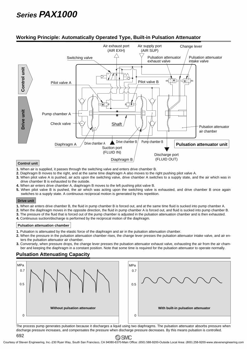
Working Principle: Automatically Operated Type, Built-in Pulsation Attenuator
Drive unit
1. Pulsation is attenuated by the elastic force of the diaphragm and air in the pulsation attenuation chamber.2. When the pressure in the pulsation attenuation chamber rises, the change lever presses the pulsation attenuator intake valve, and air en-
ters the pulsation attenuator air chamber.3. Conversely, when pressure drops, the change lever presses the pulsation attenuator exhaust valve, exhausting the air from the air cham-
ber and keeping the diaphragm in a constant position. Note that some time is required for the pulsation attenuator to operate normally.
Pulsation attenuation chamber
Control unit
Switching valve
Pilot valve A Pilot valve B
Diaphragm A Drive chamber A Drive chamber B Pump chamber B
Check valve ShaftPulsation attenuatorair chamber
Pulsation attenuator unit
Pulsation attenuatorexhaust valve
Pulsation attenuator intake valve
Change lever
Pump chamber A
Air supply port(AIR SUP)
Air exhaust port(AIR EXH)
Discharge port(FLUID OUT)
Suction port(FLUID IN)
Co
ntr
ol u
nit
Dri
ve u
nit
Diaphragm B
Pulsation Attenuating Capacity
With built-in pulsation attenuator
The process pump generates pulsation because it discharges a liquid using two diaphragms. The pulsation attenuator absorbs pressure when discharge pressure increases, and compensates the pressure when discharge pressure decreases. By this means pulsation is controlled.
0.5
0
0.7
MPa
Without pulsation attenuator
MPa
0.5
0
0.7
1. When air is supplied, it passes through the switching valve and enters drive chamber B.2. Diaphragm B moves to the right, and at the same time diaphragm A also moves to the right pushing pilot valve A. 3. When pilot valve A is pushed, air acts upon the switching valve, drive chamber A switches to a supply state, and the air which was in
drive chamber B is exhausted to the outside.4. When air enters drive chamber A, diaphragm B moves to the left pushing pilot valve B. 5. When pilot valve B is pushed, the air which was acting upon the switching valve is exhausted, and drive chamber B once again
switches to a supply state. A continuous reciprocal motion is generated by this repetition.
1. When air enters drive chamber B, the fluid in pump chamber B is forced out, and at the same time fluid is sucked into pump chamber A. 2. When the diaphragm moves in the opposite direction, the fluid in pump chamber A is forced out, and fluid is sucked into pump chamber B. 3. The pressure of the fluid that is forced out of the pump chamber is adjusted in the pulsation attenuation chamber and is then exhausted.4. Continuous suction/discharge is performed by the reciprocal motion of the diaphragm.
692
Series PAX1000
Courtesy of Steven Engineering, Inc.-230 Ryan Way, South San Francisco, CA 94080-6370-Main Office: (650) 588-9200-Outside Local Area: (800) 258-9200-www.stevenengineering.com
<Starting and Stopping> Refer to circuit example (1)1. Connect air piping to the air supply port <AIR SUR> and connect piping for the fluid to be transferred to the suction port <FLUID IN>
and the discharge port <FLUID OUT>.2. Using a regulator, set the pilot air pressure within the range of 0.2 to 0.7 MPa. Then, the pump operates when power is applied to the 3
port solenoid valve of the air supply port <AIR SUP>, the sound of exhaust begins from the air exhaust port <AIR EXH> and fluid flows from the suction port <FLUID IN> to the discharge port <FLUID OUT>.At this time, the ball valve on the discharge side is in an open state. The pump performs suction with its own power even without priming. (Dry state suction lifting range: max. 2 m) To restrict exhaust noise, attach a silencer (AN200-02: option) to the air exhaust port <AIR EXH>.
3. To stop the pump, exhaust the air pressure being supplied to the pump by the 3 port solenoid valve of the air supply port <AIR SUP>. The pump will also stop if the ball valve on the discharge side is closed.
<Discharge Flow Rate Adjustment>1. Adjustment of the flow rate from the discharge port <FLUID OUT> is performed with the ball valve connected on the discharge side or
the throttle connected on the air exhaust side. For adjustment from the air side, use of the silencer with throttle ASN2 (port size 1/4) connected to the air exhaust port <AIR EXH> is effective. Refer to circuit example (1).
2. When operating with a discharge flow rate below the specification range, provide a by-pass circuit from the discharge side to the suction side to ensure the minimum flow rate inside the process pump. With a discharge flow rate below the minimum flow rate, the process pump may stop due to unstable operation. Refer to circuit example (2). (Minimum flow rates: PAX1000 0.5 l /min)
<Reset Button>1. When the pump stops during operation, press the reset button. This makes it possible to restore operation in case the switching valve
becomes clogged due to foreign matter in the supply air. Maintenance is necessary if the reset button needs to be pressed frequently.
Operation
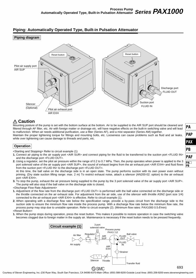
Piping: Automatically Operated Type, Built-in Pulsation Attenuator
Piping diagram
Pilot air supply portAIR SUP
Pilot air exhaust portAIR EXH
Silencer(Optional)
Reset button Reset button
Discharge portFLUID OUT
Suction portFLUID IN
PROCESS PUMP
CautionMounting posture of the pump is set with the bottom surface at the bottom. Air to be supplied to the AIR SUP port should be cleaned and filtered through AF filter, etc. Air with foreign matter or drainage etc. will have negative effects on the built-in switching valve and will lead to malfunction. When air needs additional purification, use a filter (Series AF), and a mist separator (Series AM) together.Maintain the proper tightening torque for fittings and mounting bolts, etc. Looseness can cause problems such as fluid and air leaks, while over tightening can cause damage to threads and parts, etc.
Air filter
Process pumpPAX1�12
Strainer
Silencer ThrottleTransfer fluid
AIRSUP
AIREXH
FLUIDOUT
FLUIDINAir supply
Regulator Ball valve
3 portsolenoid valveCircuit example (1)
693
Series PAX1000Process PumpAutomatically Operated Type, Built-in Pulsation Attenuator
PA
PAP
PAX
PB
PAFPA�PB
Courtesy of Steven Engineering, Inc.-230 Ryan Way, South San Francisco, CA 94080-6370-Main Office: (650) 588-9200-Outside Local Area: (800) 258-9200-www.stevenengineering.com

Dimensions
AIR SUP(Pilot air supply port)Rc, NPT, G, NPTF 1/4"
AIR EXH(Pilot air exhaust port)Rc, NPT, G, NPTF 1/4"
(175)
120
Bottom
32.5 45.5
FLUID INRc, NPT, G, NPTF 1/4", 3/8"
FLUID OUTRc, NPT, G, NPTF 1/4", 3/8"
75 5
23
Reset button
110
33
4529
125
69
FLUIDIN
AIRSUP
AIREXH
FLUIDOUT
PROCESS PUMP
RESET
Silencer : AN200-02(Option)
1057.5
100
10.5
4 x M8(Hexagonal bolt M6 is insertable)
694
Series PAX1000
Courtesy of Steven Engineering, Inc.-230 Ryan Way, South San Francisco, CA 94080-6370-Main Office: (650) 588-9200-Outside Local Area: (800) 258-9200-www.stevenengineering.com

Caution on Design
Warning
Caution
Product Specific Precautions 1Be sure to read before handling.Refer to front matters 42 and 43 for Safety Instructions.
Series PA�
1. Confirm the specifications.Give careful consideration to operating conditions such as the application, fluid and environment, and use the product within the operating ranges specified in this catalog.
2. Fluids• For the compatibility between the materials composing the
product and the fluids, check the compatibility check list. Since the compatibility of the fluid used may vary depending on its type, additives, concentration, temperature, etc., give sufficient consideration when selecting the material.
• For fluids other than those listed on the check list, please consult us. Also, use them within the range of the operating fluid temperatures.
• If foreign matters are mixed in the fluid, these may cause abrasion of the inside of the pump resulting in a problem. Use an appropriate filter (strainer) to remove them. In gener-al, 80 to 100 mesh (150 to 180 µm) filters are recommended.
• When transferring a coagulable liquid, take measures to pre-vent it from coagulating in the pump.
3. Water hammerIf a valve is operated abruptly etc., a high pressure may be ap-plied due to water hammer. Take measures to prevent pres-sures higher than specified from being applied.<Examples of measures>• Use a water hammer resistant valve to reduce the valve clos-
ing speed.• Use an elastic piping material such as rubber hose or an ac-
cumulator to absorb the impact pressure.
4. Liquid sealsProvide a relief valve in the system to prevent it from becom-ing a liquid-sealed circuit.
5. Fluid pressureDo not pressurize or decompress the fluid supplied.
6. Ensure space for maintenance.Secure the space required for maintenance and inspection. Take into consideration also leakage from the product. When transferring a flammable liquid or a liquid that may affect the human body or environment, take measures including fire ban and keeping the area off limits.
7. Use a design which prevents reverse pressure and reverse flow.If reverse pressure or flow occurs, this can cause equipment damage or malfunction, etc. Take safety measures in design-ing the circuit.
8. Measures against static electricityTake measures against static electricity as static electricity may occur depending on the fluid.
9. Cannot be used for transferring gases.If transferring gases, the product cannot provide sufficient transfer volume as it should due to the nature of compression. Besides, as the operational cycle is too short, unexpected mal-functions may occur within short periods of time. Therefore, do not operate the product for a long period of time with no liquid inside or with gas-liquid mixing.
10. Condensation and freezing of the pilot portFor the automatically operated type, the location around the switching valve and the air exhaust port can cool down quickly due to expansion of the supply air, and this may cause con-densation on the piping and the condensation may freeze dur-ing operation in winter. Take measures to ensure that water droplets from condensation are not splashed onto any electric parts or equipment.
1. Suspension of the pump operation• When the process pump is started or stopped by the pilot air
for the automatically operated type, use a 3-port solenoid valve to discharge the residual pressure. If the pump should stop while consuming the residual pressure, the built-in pilot air switching unit may become unstable and unable to be re-started. If it cannot be restarted, press the reset button.
• For the air operated type, combine an exhaust center 5-port solenoid valve or a 3-port solenoid valve for residual pres-sure release and a 4-port solenoid valve for driving the pump to discharge the residual pressure inside the pump when stopping it. If the pump is pressurized during suspension, its life will become shorter.
2. Use the constant pilot air pressure.The automatically operated type of some models adopts an air spring for the built-in air control circuit, and the pump may mal-function and stop when the pilot air pressure fluctuation ex-ceeds 50 kPa.
731
PA
PAP
PAX
PB
PAFPA�PB
Courtesy of Steven Engineering, Inc.-230 Ryan Way, South San Francisco, CA 94080-6370-Main Office: (650) 588-9200-Outside Local Area: (800) 258-9200-www.stevenengineering.com

Mounting Air Supply
Caution Warning
Product Specific Precautions 2Be sure to read before handling.Refer to front matters 42 and 43 for Safety Instructions.
Series PA�
1. Read the instruction manual before mounting the product.Read the instruction manual carefully and understand the con-tents before mounting the product. The manual should also be kept where it can be referred to whenever necessary.
2. Open the sealed package inside a clean room.Products specified for clean room are sealed and double pack-aged inside a clean room. We recommend that the inner pack-age should be opened inside a clean room or clean environ-ment.
3. Confirm the mounting orientation of the product.Since the mounting orientation varies depending on the prod-uct, check it in the instruction manual or the specifications herein.Also, secure all specified mounting positions when using the product.If the propagation of the vibration of the pump is not accept-able, insert vibro-isolating rubber when mounting.
Piping
Caution1. Flush the piping.
Flush and clean the piping before connecting the product. Any dirt or scale and the like left in the piping may cause malfunction or failure.
2. Use fittings with resin threads when connecting pip-ing to the product with resin threads at the ports.Using fittings with metal threads may cause damage to the ports.
3. Tighten screws with proper tightening torque.When screwing fittings into the product, tighten them with proper tightening torque as shown below.
1. Use clean air.Do not use compressed air that includes chemicals, synthetic oils containing organic solvents, salinities or corrosive gases, etc., as it can cause damage or malfunction.
2. Pay attention to avoid freezing when operating the product in low temperatures.The equipment operates while expanding the compressed air. During this time, the temperature inside the product decreases due to adiabatic expansion. If the ambient temperature is low, using compressed air containing a lot of moisture may cause freezing because heat cannot be gained from the surround-ings. In this case, take freeze prevention measures by using a membrane air dryer (such as series IDG).
Operating Environment
Warning1. Do not use in the following environments, as this
can cause failure.1) Locations with an atmosphere of corrosive gases, organic
solvents or chemical solutions, and where there may be contact with the same.
2) Locations where there is contact with sea spray, water or steam.
3) Locations where ultraviolet deterioration or overheating of resin may occur due to direct sunlight.
4) Locations near heat sources with poor ventilation (heat sources should be shielded by heat insulating material).
5) Locations with impact or vibration.6) Locations with excessive moisture and dust.
2. The product cannot be used under water.Do not use the product immersing it in water (liquid). Other-wise, liquid will enter the openings inside the product, resulting in malfunction.
3. Compressed air with low dew pointUsing super dry air as the fluid may affect the reliability (ser-vice life) of the equipment, because the lubrication characteris-tics inside the equipment will deteriorate. Please consult with SMC when using it.
Caution1. Quality of operating air
• Be sure to use only air filtrated by a micro mist separator (such as series AMD). Use of a super mist separator (such as series AME) is recommended to extend maintenance in-tervals.
• If a pump is operated by dried air and N2 gas, etc., the deteri-oration of the gaskets inside the switching valve will be ac-celerated and may result in substantially shortening the life span of the product.
Connection thread
PA3000, PA5000, PAX1000Proper tightening torque (N·m)
Rc, NPT, G, NPTF 1/4
Rc, NPT, G, NPTF 3/8
Rc, NPT, G, NPTF 1/2
Rc, NPT, G, NPTF 3/4
12 to 14
22 to 24
28 to 30
28 to 30
Connection thread
PA3300, PAP3300, PAF3000, PAF5000Proper tightening torque (N·m)
Rc, NPT, G, NPTF 1/8
Rc, NPT, G, NPTF 1/4 (PAF3000)
Rc, NPT, G, NPTF 1/4
Rc, NPT, G, NPTF 3/8
Rc, NPT, G, NPTF 3/4
0.4 to 0.5
0.8 to 1
1.5 to 2
2 to 2.5
4 to 5
Connection thread
PAX1000Proper tightening torque (N·m)
M5
Rc, NPT, G, NPTF 1/8
1/6 turn after tightening by hand
2 to 3
732Courtesy of Steven Engineering, Inc.-230 Ryan Way, South San Francisco, CA 94080-6370-Main Office: (650) 588-9200-Outside Local Area: (800) 258-9200-www.stevenengineering.com

Maintenance
Warning
Product Specific Precautions 3Be sure to read before handling.Refer to front matters 42 and 43 for Safety Instructions.
Series PA�
1. Perform maintenance after consulting the instruc-tion manual.Obtain the instruction manual for the equipment from SMC or our distributor and have sufficient knowledge of the equipment before performing maintenance. Incorrect handling may cause damage or malfunction of the equipment or system.
2. Perform maintenance work after confirming the safety of the system.Turn off the compressed air and power supply and exhaust any remaining compressed air in the system before removing the equipment and the compressed air supply/exhaust unit. Discharge the residual liquid or sufficiently displace it as nec-essary. Also, when reinstalling the equipment or restarting it after replacement, confirm the safety of the product before checking that it operates normally.
3. Do not disassemble the product, as disassembly will invalidate the product's warranty. When disassembly is necessary, please consult with SMC or our distributor.
4. Drain dischargeOperating the system with drain accumulated in the equipment or piping may cause malfunction of the equipment, splash over into the downstream side, or unexpected accident. Periodically discharge drain from components including the air filter.
5. Caution when transferring a high-temperature fluidThe product itself will become hot due to the high-temperature fluid. Since touching the product directly may cause burns, al-low sufficient time for the product to cool down when transfer-ring a high-temperature fluid. The measurement of the product temperature is recommended to confirm the safety of the sys-tem before performing work.
6. Caution when a temperature history cycle is ap-plied.When a temperature history (heat cycle) is applied for Series PAF3000/5000, the resin thread may extend. Additionally tighten with the specified torque (M3: 0.11 to 0.12 N·m) to pre-vent liquid leakage.
2. Service life of diaphragm and maintenance of con-sumable items• Regular maintenance is required for items including dia-
phragms, check valves, switching valves, pilot valves and manual caps.
• If the operating cycle of the process pump exceeds the ser-vice life of diaphragm, the diaphragm may be damaged due to deterioration. If it is damaged, the fluid will leak from the pilot air exhaust port and the air will blow out into the liquid circuit. Consider the pump operation (breathing, decline of discharge pressure, etc.) and the reference service life of diaphragm, and conduct necessary maintenance as early as possible.
• Items such as check valves, switching valves, pilot valves and manual caps may experience malfunction earlier than the diaphragm depending on the operating conditions. Please conduct periodic maintenance.
• When conducting maintenance, obtain the necessary parts indicated in the maintenance parts list (see page 727), and perform work according to the maintenance and instruction manuals.
[Calculation of reference service life (days) of dia-phragm]<Automatically operated type>
Reference service life (days) =A (amount of discharge per cycle) x B (reference number of cycles in service life)
Flow (l/min) x Operating time per day (hour) x 60 (min)<Air operated type>
The amount of discharge per cycle for the air operated type varies depending on the piping resistance. Therefore, calcu-late the service life (days) using the operating frequency of a solenoid valve.Reference service life (days) = B (reference number of cycles in service life)
Operating frequency of solenoid valve (Hz) x 60 (sec) x Operating time per day (hour) x 60 (min)
Caution1. Caution when transferring a highly penetrating liq-
uidWhen transferring a liquid that is highly penetrating through fluoropolymer, components of the transfer liquid may enter the openings inside the equipment. Also, they may become at-tached to the external surface of the equipment. In this case, take the same measures as handling the transfer liquid.
PA3�10
PA3�20
PA3�13
PA5�10
PA5�20
PA5��3
PA (P) 3310
PA (P) 3313
PAX1000
PB1011
PB1013
PAF3410
PAF3413
PAF5410
PAF5413
Air operated type
Automaticallyoperated type
Air operated type
Automatically operated type
Air operated type
Automatically operated type
Solenoid valve driving
Air operated type
Automatically operated type
Air operated type
Automatically operated type
Air operated type
PTFE
NBR
PTFE
PTFE
NBR
PTFE
PTFE
PTFE
PTFE
PTFE
PTFE
Approx. 0.04 l
Approx. 0.022 l ∗
Approx. 0.10 l
Approx.0.09 l ∗
Approx. 0.025 l
Approx. 0.037 l
Approx. 0.021 l
Approx. 0.004 l
Approx. 0.004 l
Approx. 0.054 l
Approx. 0.050 l ∗
Approx. 0.130 l
Approx. 0.190 l ∗
100 million cycles
50 million cycles
50 million cycles
50 million cycles
50 million cycles
50 million cycles
20 million cycles
50 million cycles
Approx. 75 ml
Approx. 315 ml
Approx. 85 ml
Approx. 90 ml
Approx. 9 ml
Approx. 105 ml
Approx. 100 ml
Approx. 600 ml
Model Operatingmethod
Diaphragmmaterial
Amountof dischargeper cycle A
Reference numberof cycles
in service life B
Volumeinside pump(wetted part)
∗ The amount of discharge per cycle for the air operated type is indicated assum-ing no piping resistance.
Maintenance
Caution
Automaticallyoperated type
733
PA
PAP
PAX
PB
PAFPA�PB
Courtesy of Steven Engineering, Inc.-230 Ryan Way, South San Francisco, CA 94080-6370-Main Office: (650) 588-9200-Outside Local Area: (800) 258-9200-www.stevenengineering.com

Lubrication Caution on Handling
Caution Warning1. The pump can be used without lubrication.
Do not lubricate the air operated type, the PAF series.
2. If lubricating the pump, continue lubrication.If lubricating a pump other than the air operated type or the PAF series, use turbine oil Class 1 (with no additives) ISO VG 32, and be sure to continue lubricating the pump.
1. Test before using with the actual equipment.Test the pump before using it with the actual equipment. Even if there is no problem in a short-term test, the liquid may pene-trate through the fluoropolymer diaphragm causing malfunc-tion in the pump air circuit.
2. StorageIn the case of long-term storage after use, first thoroughly re-move the liquid, and clean and dry the inside to prevent deteri-oration of the pump materials.
3. After a long period of non-use, perform a trial run prior to operation.
Product Specific Precautions 4Be sure to read before handling.Refer to front matters 42 and 43 for Safety Instructions.
Series PA�
734Courtesy of Steven Engineering, Inc.-230 Ryan Way, South San Francisco, CA 94080-6370-Main Office: (650) 588-9200-Outside Local Area: (800) 258-9200-www.stevenengineering.com