Embed Size (px)
Citation preview

A LYAPUNOV-FUNCTION BASED CONTROL FOR A THREE-PHASE
SHUNT HYBRID ACTIVE POWER FILTER
A Thesis Submitted in Partial Fulfillment of the Requirements
For the Award of the Degree of
Master of Technology
In
Electrical Engineering
by
Smruti Dash
Department of Electrical Engineering
National Institute of Technology
Rourkela
2011 – 2013
A LYAPUNOV-FUNCTION BASED CONTROL FOR A THREE-PHASE
SHUNT HYBRID ACTIVE POWER FILTER
A Thesis Submitted in Partial Fulfillment of the Requirements
For the Award of the Degree of
Master of Technology
In
Electrical Engineering
by
Smruti Dash
Under the guidance of
Prof. K.B.Mohanty
Department of Electrical Engineering
National Institute of Technology
Rourkela
2011 - 2013

National Institute of Technology
Rourkela
CERTIFICATE
This is to certify that the thesis entitled “A LYAPUNOV-FUNCTION BASED CONTROL
FOR A THREE-PHASE SHUNT HYBRID ACTIVE POWER FILTER” submitted by Miss.Smruti Dash
bearing Roll No.211EE3145 in partial fulfillment of the requirements for the award of
Master of Technology Degree in Electrical Engineering specializing in “Control and
Automation” at the National Institute of Technology, Rourkela (Deemed University) is
an authentic work carried out by her under my supervision and guidance.
To the best of my knowledge, the matter embodied in the thesis has not been
submitted to any other University / Institute for the award of any Degree or Diploma.
Prof. K.B.Mohanty
National Institute of Technology
Rourkela-769008

Page i
ACKNOWLEDGEMENT
I have taken efforts in this project; it would not have been possible without the kind support and
help of many individuals. I would like to extend my sincere thanks to all of them.
I would like to express my deep sense of profound gratitude to my honorable, esteemed guide,
Prof. K.B.Mohanty for his guidance and enthusiastic support. His valuable discussions without
which my work may not be in present form.
The discussions held with the friends is worth to mention especially Mahendra Joshi, Pankaj
Kumar Jha, Ankush Kumar, Kushal Chaudhari, Rajashree Biswas and Sunita Mohanta , for all
the thoughtful and mind stimulating discussions we had ,which prompted us to think beyond the
obvious.
My due thanks to Professors A.K.Panda, Sandip Ghosh, Subhojit Ghosh and S.Samanta of
the Electrical Engineering department for their course work and constant encouragement which
helped me in completing my dissertation work.
I mention my indebtedness to my father Shri.L.N.Dash and mother Smt.Shashi Lata Dash for
their love and affection and their constant support which made me believe in me.
I would like to thank to all those who are a part of this project whose names could have not been
mentioned here.
Smruti Dash

Page ii
Dedicated to Guruji, parents and friends

Page iii
ABSTRACT
The denomination Power quality by and large refers to maintaining approximal sinusoidal power
distribution bus voltage at rated magnitude and frequency. This is mainly affected by the
generation of harmonics. Even though electronic and non-linear devices are flexible, economical
and energy efficient, they may degrade power quality by creating harmonic currents and
consuming excessive reactive power.
A family of various shunt hybrid active power filters has been explored in shunt
and series configurations to compensate for different types of nonlinear loads. They provide
controlled current injection to remove harmonic current from the source side of electric system
and also can improve the power factor.
In this thesis, first three-phase system is implemented without filter, its source current,
compensating current and THD values are studied, then PI control strategy is applied then the
differences in THD are compared. The PI feedback compensation design starts with the small
signal system’s transfer function. Then a Lyapunov-function based control algorithm for a SH-
APF is proposed and implemented to enhance its response to compensation of harmonics of non-
linear loads. The obtained results have demonstrated the ability to compensate the current
harmonics effectively under distorted source conditions. The fluctuation in the dc bus voltage of
the filter depends on the compensation speed of the outer loop that regulates the dc bus voltage.
A sudden increase in the load power of this rectifier type non-linear load results in a decrease of
the dc bus voltage of the SH-APF system which recovers within a few cycles.

Page iv
Contents
ACKNOWLEDGEMENT ................................................................................................... i
ABSTRACT ....................................................................................................................... iii
CONTENTS ....................................................................................................................... iv
LIST OF FIGURES .......................................................................................................... vii
LIST OF ABBREVIATIONS .......................................................................................... ix
CHAPTER 1 ...................................................................................................................... 1
1 INTRODUCTION ...................................................................................................... 2
1.1 Overview ............................................................................................................... 2
1.2 Significance of Power Quality .............................................................................. 2
1.2.1 There are four major reasons for the increased concern ......................................... 3
1.3 Harmonic Sources And Effects ............................................................................. 3
1.4 Motivation ............................................................................................................. 6
1.5 Literature Review .................................................................................................. 7
1.6 Objective ............................................................................................................... 7
1.7 Organization of The Thesis ................................................................................... 8
CHAPTER 2 9
2 HARMONIC POWER FILTERS ........................................................................... 10
2.1 Current source non-linear load ............................................................................ 10
2.2 Voltage source non-linear load ........................................................................... 10
2.3 Types of power filter ........................................................................................... 11
2.4 Limitation of active power filter ......................................................................... 12
2.5 Limitation of Passive power filter ....................................................................... 13
2.6 Increasing demand of shunt hybrid active power filter ..................................... 13

v
2.7 Classification of hybrid filters for power quality improvement .......................... 14
2.8 Conclusion ........................................................................................................... 15
CHAPTER 3 16
3 SH-APF ...................................................................................................................... 17
3.1 Harmonic Extraction ........................................................................................... 18
3.2 Current modulator ............................................................................................... 18
3.3 Modeling of SH-APF .......................................................................................... 19
3.4 Conclusion ........................................................................................................... 22
CHAPTER 4 23
4 PI CONTROL ........................................................................................................... 24
4.1 Blocks describing control strategy ...................................................................... 25
4.2 A-B-C to d-q transformation ............................................................................... 26
4.2.1 id-iq Method ...................................................................................................... 26
4.3 Modulation Method ............................................................................................. 27
4.4 Harmonic detection and Logic circuit block ....................................................... 28
4.5 Results and discussion using PI control strategy ................................................ 30
4.6 Simulation without any filter............................................................................... 31
4.7 Similation with Passive Shunt Filter and PI control ........................................... 32
4.8 Conclusion ........................................................................................................... 34
CHAPTER 5 35
5 INTRODUCTION .................................................................................................... 36
5.1 Simulation ........................................................................................................... 37
5.2 Simulation using Passive shunt filter and Lyapunov control .............................. 37
5.3 Comparison of THD’s ......................................................................................... 40
5.4 THD Comparison ................................................................................................ 41
CHAPTER 6 42
6 CONCLUSION ......................................................................................................... 43

vi
6.1 Major contribution............................................................................................... 43
6.2 Scope for Future work ......................................................................................... 43
7 REFERENCES ......................................................................................................... 44

vii
List of Figures
Figure 1:Harmonically distorted waveform of Voltage and Current .......................... 4
Figure 2: Typical CSNL ................................................................................................. 10
Figure 3:Typical VSNL .................................................................................................. 11
Figure 4:Types of power filters ...................................................................................... 11
Figure 5:Hybrid filter as combination of PSE (PFss) and PSH (PFsh) filters ........... 14
Figure 6:Hybrid filter as combination of PSE (PFss1), PSH(PFsh) and passive-series
(PFss2) filters ............................................................................................................................... 14
Figure 7: Hybrid filter as combination of PFsh1 and PFsh2 and PFss1 filters ......... 15
Figure 8:Hybrid filter as combination of PSH (PFsh) and PSE (PFss) filters .......... 15
Figure 9: basic configuration of SH-APF ..................................................................... 17
Figure 10: tree of control unit ........................................................................................ 18
Figure 11: Configuration of SH-APF ............................................................................ 19
Figure 12: Block diagram of typical PI control............................................................ 24
Figure 13 System diagram for three phase SH-APF topology .................................... 25
Figure 14: PWM technique ............................................................................................ 28
Figure 15: Reference compensating current generation circuit ................................. 29
Figure 16: Logic circuit and internal circuit ................................................................ 29
Figure 17: source voltage ................................................................................................ 31
Figure 18:Load current .................................................................................................. 31
Figure 19:Source current ............................................................................................... 31
Figure 20: Load Current ................................................................................................ 32
Figure 21: Load current ................................................................................................. 32
Figure 22: Source current without control ................................................................... 32
Figure 23:compensating current ................................................................................... 33
Figure 24: Source voltage ............................................................................................... 33
Figure 25: Source current after compensation and control ........................................ 33
Figure 26: Source current in single phase after compensation................................... 34
Figure 27:DC-LINK Voltage ......................................................................................... 34
Figure 28:LYAPUNOV control strategy ...................................................................... 36

viii
Figure 29: Load current ................................................................................................. 37
Figure 30:Load current in single phase ........................................................................ 37
Figure 31:Source voltage ................................................................................................ 37
Figure 32: Source current .............................................................................................. 38
Figure 33:Source current in single phase ..................................................................... 38
Figure 34: Source current after compensation ............................................................ 38
Figure 35:Source current after compensation in single phase.................................... 39
Figure 36: DC-LINK Voltage ........................................................................................ 39
Figure 37:THD without any filter ................................................................................. 40
Figure 38:THD with PASSIVE-SHUNT and PI Controller ....................................... 40
Figure 39: THD with LYAPUNOV Control .............................................................................. 41

ix
LIST OF ABBREVIATIONS
APF Active power filter
IBC Interleaved buck converter
PPF Passive power filter
Hz Hertz
IEEE Institute of Electrical and Electronics Engineers
HVDC High voltage dc transmission
KV kilovolt
MVA megavolt ampere
MVAR mega volt amps reactive
MW megawatt
p.u. Per unit
PCC point of common coupling
PI Proportional Integral
PWM Pulse Width Modulation
RMS root mean square
SH-APF Shunt Hybrid-Active Power Filter
VAR Volt ampere reactive
THD Total harmonic distortion

Page 1
CHAPTER-1
INTRODUCTION
Introduction
Literature Review
Project motivation
Project objective
Thesis organization

Chapter 1 Introduction
Page 2
1 Introduction This chapter gives the overview of the work. This comprises of a brief description of power
quality, harmonic sources and effects followed by literature survey. The objectives and
organization of the thesis are mentioned in this chapter.
1.1 Overview Over the past 100 years, the electric power industry continues to shape and contribute to the
benefit, progression and technological advances of the human race. The growth of electrical
energy consumption in the world has been nothing but phenomenal. Electrical energy is the most
efficient and popular form of energy because it can be easily converted to different forms of
energies at high efficiency and reasonable cost. The electric utility industry can trace its
beginnings to the early 1880s. During that period several companies were formed and installed
water-power driven generation for the operation of arc lights for street lighting; the first real
application for electricity in the United States. In 1882 Thomas Edison placed into operation the
historic Pearl Street steam-electric plant and the pioneer direct current distribution system, by
which electricity was supplied to the business offices of downtown New York. By the end of
1882, Edison’s company was serving 500 customers that were using more than 10,000 electric
lamps.
1.2 Significance of Power Quality
All electrical devices are prone to failure or malfunction when exposed to one or more power quality
problems. The devices [1] may be an electric motor or a transformer, a generator, a computer, a
printer, communication paraphernalia or a house hold appliance. All these devices and other react
adversely to power quality issues depending on the severity of problem. Both electric expediencies
and end users of electric power are becoming increasingly anxious about the quality of electric
power. Since the late 1980s the term power quality has become one of the most prolific
buzzwords in the power industry. It is a brusque concept for a multitude of individual types of
power system disturbances. The issues that fall under this curt are not necessarily new. A
systematic approach is being used rather than handling them as individual problems this is what
engineers are now attempting to deal with these issues.

Chapter 1 introduction
Page 3
1.2.1 There are four major reasons for the increased concern:
1. The progeny of Newer-generation load equipment, with microprocessor-based controls
and power electronic devices, is more sensitive to power quality variations than was
equipment used in the past.
2. The increasing emphasis on overall power system efficiency has resulted in continued
growth in the application of devices such as high-efficiency, adjustable-speed motor
drives and shunt capacitors for power factor correction to reduce losses. This is resulting
in increasing harmonic levels on power systems and has many people concerned about
the future impact on system capabilities.
3. End users have an increased awareness of power quality issues. Utility customers are
becoming better informed about such issues as interruptions, sags, and switching
transients and are challenging the utilities to improve the quality of power delivered.
4. Many things are now interconnected in a network. Integrated processes mean that the
failure of any component has much more important consequences.
1.3 Harmonic sources and effects
A good assumption for most utilities in the United States is that the sine-wave voltage generated
in central power stations is very good. In most areas, the voltage found on transmission systems
typically has much less than 1.0 percent distortion. However, the distortion increases closer to
the load. At some loads, the current waveform barely resembles a sine wave. This has given rise
to the widespread use of the term harmonics to describe distortion of the waveform. Harmonics
problems counter many of the conventional rules of power system. Design and operation that
consider only the fundamental frequency. Therefore, the engineer is faced with unfamiliar
phenomena that require unfamiliar tools to analyze and unfamiliar equipment to solve.
Harmonic distortion is not a new phenomenon on power systems. Concern over distortion has
ebbed and flowed a number of times during the history of ac electric power systems. Scanning
the technical literature of the 1930s and 1940s, one will notice many articles on the subject. At
that time the primary sources were the transformers and the primary problem was inductive
interference with open-wire telephone systems. The forerunners of modern arc lighting were
being introduced and were causing quite a stir because of their harmonic content not unlike the

Chapter 1 introduction
Page 4
stir caused by electronic power converters in more recent times. We can define harmonic [4] as
the frequency which is integer multiple of the fundamental frequency (i.e. 50 or 60 Hz). For
example second harmonic is two time of fundamental (i.e. 100 or 120 Hz), similarly for third
harmonic it is thrice of the fundamental component (i.e. 150 or 180 Hz) and so on. Fig 1.1 shows
harmonics up to 3rd
order with respect to the fundamental frequency.
Figure 1:Harmonically distorted waveform of Voltage and Current
A measure of harmonic content in a signal is the total harmonic distortion (THD).The
percentage THD in a voltage is given by equation 1.
Equation 1-1
Where Vn denotes the magnitude of the nth harmonic voltage and v1 is the magnitude of the
fundamental voltage. A similar expression can also be written for current harmonics. Usually for
good quality power it is recommended that the THD be less than 3%.
In general, harmonic sources are given below:
Converters, Devices which includes semi-conductor elements
Generators, Motors, Transformers
Lightening equipments working by gas discharge principle
Photovoltaic systems, Computers, Electronic ballasts
Harmonic Current Harmonic Voltage

Chapter 1 introduction
Page 5
Uninterruptable power supplies, Switching power supplies
Welding machines
Control circuits
Frequency converters
Static VAR compensators
Arc furnaces
HVDC transmission systems
Electrical Communication systems
Harmonic currents cause problems both on the supply system and within the installation. The
effects [2] and the solutions are very different and need to be addressed separately; the measures
that are appropriate to controlling the effects of harmonics within the installation may not
necessarily reduce the distortion caused on the supply and vice versa.
There are several common problem areas caused by harmonics: -Problems caused by
harmonic currents:
overloading of neutrals
overheating of transformers
nuisance tripping of circuit breakers
over-stressing of power factor correction capacitors
Skin effect
Problems caused by harmonic voltages:
Voltage distortion in induction motors
zero-crossing noise
Problems caused when harmonic currents reach the supply
There are a number of methods to modify adverse system responses to harmonics:
(i) Add a shunt filter. Not only does this shunt a troublesome harmonic current off the
system, but it completely changes the system response, most often, but not always, for the
better.
(ii) Add a reactor to detune the system. Harmful resonances generally occur between the
system inductance and shunt power factor correction capacitors. The reactor must be added

Chapter 1 introduction
Page 6
between the capacitor and the supply system source. One method is to simply put a reactor in
series with the capacitor to move the system resonance without actually tuning the capacitor to
create a filter. Another is to add reactance in the line.
(iii) Change the capacitor size. This is often one of the least expensive options for both
utilities and industrial customers.
(iv) Move a capacitor to a point on the system with a different short-circuit impedance or
higher losses. This is also an option for utilities when a new bank causes telephone interference
moving the bank to another branch of the feeder may very well resolve the problem. This is
frequently not an option for industrial users because the capacitor cannot be moved far enough to
make a difference.
(v) Remove the capacitor and simply accept the higher losses, lower voltage, and power
factor penalty. If technically feasible, this is occasionally the best economic choice.
1.4 Motivation
The electric power industry delivers electric energy to its customers which they, in turn, use for
variety of purposes. Harmonic currents produced by non-linear loads can interact adversely with
the utility supply system. The interaction often gives rise to voltage and current harmonic
distortion observed in many places in the system.
Passive and active filters are used to suppress the harmonic distortions. The simplest
conventional solution is the passive filtering to mitigate the harmonic distortion. The use of
passive element does not always respond correctly to the dynamics of the power distribution
systems although it is simple in designing. Active filters can be applied to a single non-linear
load or many. The harmonic current from the source side of electric system can be removed by
injection of controlled current and also by this method we can improve the power factor.
This work presents a method capable of designing power filters to reduce harmonic distortion
and correct the power factor by which power quality of a distribution system can be improved. A
comparative study between control approaches and compensation performances shows that the
hybrid active power filter based on these control strategies can eliminate harmonic current
effectively.

Chapter 1 introduction
Page 7
1.5 Literature Review
The literature study for this work starts from Harmonic sources and filtering approaches [1-6]
wherein it is described that non-linear loads can be characterized into two types of harmonic
sources: current source type non-linear loads and voltage type of non-linear loads. These two
types of harmonic sources have completely distinctive and dual properties and characteristics.
Brief study of Hybrid filters and various shunt and series configurations of hybrid filters have
been explored in [7-8].The Modeling is necessary whenever analysis of control system is
required [9].The total modeling of three phase SH-APF is described in this paper followed by dq-
transform[10].In the paper titled “Lyapunov-function based control for a three-phase shunt
hybrid active power filter”,S.Rahemani,A.Hamadi and K.Al.Haddad a Lyapunov control
technique is developed for a three-phase SH-APF to compensate harmonics generated by non-
linear loads and is applied for balanced operation.Liu.Wei and Zhang Da-wei have discussed
about series hybrid active active power filter based on PID controller[11-13].Gating signal
techniques have been discussed in papers[14-15],then PWM techniques have been discussed
in[17],A new control strategy for single phase shunt APF’s is proposed based on Lyapunov’s
stability theory[18-19],The theoretic analysis by reference current generating method by Jia
Zhang,Guohong Zeng[20] can reduce reactive and harmonic current effectively.
Jarupula Somlal discussed efficient improvement of Power Factor and Harmonic suppression
using MATLAB [21].Control strategies of SH-APF using fuzzy logic, neural networks and
swarm organization have been proposed in these papers [22-23].
1.6 OBJECTIVE
To provide compensation for harmonic load current components.
To study and validate the proposed Lyapunov-function based control strategy of the SH-
APF for the reduction of harmonic currents of the voltage source type of non-linear loads.
To linearize the non-linear model of three-phase SH-APF.
To implement this modulation technique to different configurations of hybrid filters
To analyze how this technique is better than others in terms of reliability and efficiency

Chapter 1 introduction
Page 8
To Simulate single phase and three phase configuration of Hybrid filters and to compare
THD of source current in both the case with the case of no compensation
1.7 Organization of the thesis
Including the introductory chapter, the thesis is divided into 5 chapters. The organization of
the thesis is presented below
Chapter-2
Various types of filters including active and passive, series and shunt configuration are
discussed. Individually advantages and disadvantages of these filters are studied, then
combining and forming a hybrid filter is explored.
Chapter-3
Detailed configuration of Shunt Hybrid Active Power Filter is studied with mathematical
modeling single phase SH-APF is simulated without any control strategy, its THD and
voltage and current waveforms of load and source are shown.
Chapter-4
Three-phase SH-APF simulation with PI control strategy in detail is discussed and the non-
linear equations are linearized using JACOBIAN and all the matlab simulations and its
results are presented.
Chapter-5
This chapter comprises of final conclusion and scope of future work, The SH-APF
employing proposed PI and Lyapunov control strategy suitable for voltage and current source
types of non-linear loads. The obtained results have demonstrated the high performance level
of SH-APF.

Page 9
CHAPTER-2
HARMONIC POWER
FILTERS
Current source type non-linear load
Voltage source type non-linear load
Types of power filters
Limitation of active filters
Limitation of passive filters
Demand of Hybrid filters
Classifications of Hybrid filters
Conclusion
Chapter 2 harmonic power control
Page 10
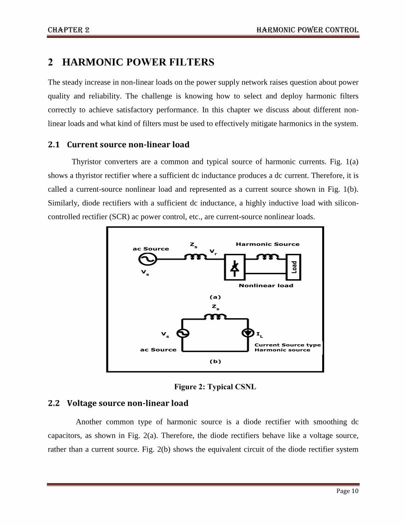
2 HARMONIC POWER FILTERS
The steady increase in non-linear loads on the power supply network raises question about power
quality and reliability. The challenge is knowing how to select and deploy harmonic filters
correctly to achieve satisfactory performance. In this chapter we discuss about different non-
linear loads and what kind of filters must be used to effectively mitigate harmonics in the system.
2.1 Current source non-linear load
Thyristor converters are a common and typical source of harmonic currents. Fig. 1(a)
shows a thyristor rectifier where a sufficient dc inductance produces a dc current. Therefore, it is
called a current-source nonlinear load and represented as a current source shown in Fig. 1(b).
Similarly, diode rectifiers with a sufficient dc inductance, a highly inductive load with silicon-
controlled rectifier (SCR) ac power control, etc., are current-source nonlinear loads.
Figure 2: Typical CSNL
2.2 Voltage source non-linear load
Another common type of harmonic source is a diode rectifier with smoothing dc
capacitors, as shown in Fig. 2(a). Therefore, the diode rectifiers behave like a voltage source,
rather than a current source. Fig. 2(b) shows the equivalent circuit of the diode rectifier system

Chapter 2 harmonic power filter
Page 11
where the diode rectifier is represented as a harmonic voltage source or voltage-source nonlinear
load.
Figure 3:Typical VSNL
2.3 Types of power filter
There are different types of power filter [7]; analyzing the current situation power filters widely
classified into three categories, Fig 4 shows these categories of power filters.
Figure 4:Types of power filters
Since the basic operating principles of active power filters [3] were firmly
established in the 1970s, for short—have attracted the attention of power electronics
researchers/engineers who have had a concern about harmonic pollution in power systems [4]–
[5]. Moreover, deeper interest in active filters has been spurred by
FILTERS
ACTIVE PASSIVE HYBRID

Chapter 2 harmonic power filter
Page 12
• the emergence of semiconductor switching devices such as insulated-gate bipolar
transistors (IGBTs) and power MOSFETs, which are characterized by fast switching capability
and insulated-gate structure;
• the availability of digital signal processors (DSPs), field-programmable gate arrays
(FPGAs), analog-to-digital (A/D) converters, Hall-effect voltage/current sensors, and operational
and isolation amplifiers at reasonable cost [6]–[13]
Modern active harmonic filters are superior in filtering performance, smaller in physical
size, and more flexible in application, compared to traditional passive harmonic filters using
capacitors, inductors, and/or resistors. However, the active filters are slightly inferior in cost and
operating loss, compared to the passive filters, even at present. Active filters intended for power
harmonic filtering, harmonic damping, harmonic isolation, harmonic termination, reactive-power
control for power factor correction and voltage regulation, load balancing, voltage-flicker
reduction, and/or their combinations.
Moreover, the active filters can be classified into pure active filters and hybrid active filters
in terms of their circuit configuration. Most pure active filters can use as their power circuit
either a voltage-source pulse width modulated (PWM) converter equipped with a dc capacitor or
a current-source PWM converter equipped with a dc inductor. At present, the voltage-source
converter is more favorable than the current-source converter in terms of cost, physical size, and
efficiency. Active filters consist of single or multiple voltage-source PWM converters and
passive components such as capacitors, inductors, and/or resistors. The active filters are more
attractive in harmonic filtering than the pure filters from both viability and economical points of
view, particularly for high-power applications [13]–[20].
2.4 Limitation of active power filter
Today modern active power filters are superior in filtering performance, smaller in
physical size and more flexible in application compared to traditional passive filters. Among the
active power filter configurations, shunt APF is the most important and most widely used in
industrial processes. It is connected in parallel with the non-linear load, thus can easily be
adapted to existing plants. Main purpose of the filter is to cancel the load current harmonics
injected to the supply but it can also implement reactive power compensation and three phase

Chapter 2 harmonic power filter
Page 13
currents balancing [23]. However the APFs have still the disadvantages of higher cost and
complexity of control.
Most researches in this field focus on the APF topology [24], harmonic detection
algorithm [25-26] and current control strategy [27-28]. However, in the application
with high reliability requirement such as aerospace, the existent voltage- source inverter based
APF would suffer from the potential “shoot-through” phenomenon. Dead time is usually
added to avoid the impulse current in the voltage-source bridge configuration based
converter. Consequently, the dead-time effect deteriorates the compensation performance.
Meanwhile, reducing the dead time effects by adjusting the control strategy will increase the
complexity of the whole system [29-30].
There are various fault condition are present in power electronics circuit. One of the
most serious faults that can occur in this circuit is the shoot-through condition that occurs when
both switches are inadvertently turned on at the same time, shorting the supply voltage. In order
to avoid short through failure, a dead-time is required in control signals. A wide variety of
protection techniques have been developed to remove the shoot-through fault if it occurs by
rapidly turning off one or both of the switches, and the majority of these techniques are based
on detecting over current conditions
2.5 Limitation of Passive power filter
Initially, lossless passive filters (LC) have been used to reduce harmonics and capacitors
have been chosen for power-factor correction of these nonlinear loads, but passive filters have
the demerits of fixed compensation, large size and resonance with the supply system.
2.6 Increasing demand of shunt hybrid active power filter
HYBRID active filters are considered one of the favored options for improving power
quality for a number of considerations. Their topologies provide inherent advantages which
combine both passive and active filter functions. Therefore, an improved-performance and cost-
effective solution to harmonic elimination is nowadays available for power quality enhancement.

Chapter 2 harmonic power filter
Page 14
2.7 Classification of hybrid filters for power quality improvement
The hybrid filters of more than three elements are rarely used because of cost and
complexity considerations and hence are not included here. These hybrid filters as a combination
of two and three active and passive elements result in a total of 52 practically valid circuit
configurations.
However, these 52 circuit configurations of hybrid filters are valid for each case of
supply system of single-phase two wire,three-phase three wire and three-phase four wire AC
systems. In each case of supply system, four basic elements of filter circuit as passive series
(PFss), passive shunt (PFsh), active series (AFss) and active shunt (AFsh) are required to
develop complete hybrid filter circuit configurations.
Figure 5:Hybrid filter as combination of PSE (PFss) and PSH (PFsh) filters
Figure 6:Hybrid filter as combination of PSE (PFss1), PSH(PFsh) and passive-series
(PFss2) filters
Buy SmartDraw!- purchased copies print this
document without a watermark .
Visit www.smartdraw.com or call 1-800-768-3729.
Buy SmartDraw!- purchased copies print this
document without a watermark .
Visit www.smartdraw.com or call 1-800-768-3729.

Chapter 2 harmonic power filter
Page 15
Figure 7: Hybrid filter as combination of PFsh1 and PFsh2 and PFss1 filters
Figure 8:Hybrid filter as combination of PSH (PFsh) and PSE (PFss) filters
2.8 Conclusion
a comprehensive review of HF’s has been presented to provide a wide exposure, classification of
HF’s in series and shunt configuration is reviewed. These hybrid filters can be considered as a
better alternative for power quality improvement owing to reduced cost, simple design and
control and high reliability compared to other options of power quality improvement.
Buy SmartDraw!- purchased copies print this
document without a watermark .
Visit www.smartdraw.com or call 1-800-768-3729.
Buy SmartDraw!- purchased copies print this
document without a watermark .
Visit www.smartdraw.com or call 1-800-768-3729.

Chapter 3 SH-APF
Page 16
CHAPTER-3
SH-APF
Harmonic Extraction
Current Modulator
Modeling of SH-APF
Conclusion

Chapter 3 SH-APF
National Institute of Technology,Rourkela Page 17
3 SH-APF
The SH-AF consists of a low-rating active power filter connected in series with a passive filter.
The SH-AF inherits the advantages of both active and passive filters and thus constitutes a viable
improved approach for harmonic compensation and provides cost-effective solutions. It damps
resonances occurring between line impedances and the passive filter. On the other hand, the
fundamental voltage drops on the passive filter components allow the shunt active power filter to
operate with a significantly lower dc-link voltage, which provides significant reduction in the
active filter power rating. Although the passive filter compensates the fifth harmonic, the active
filter is controlled such as a current-controlled voltage source aimed to compensate for load
harmonics and prohibiting them from circulating into the ac mains. A diode bridge rectifier with
RL or RC load is considered as a nonlinear load.
Actual work of an hybrid power filter is to inject the harmonics to the supply which is out
of phase with the actual harmonics so as to cancel it.Fig.9 gives the basic idea of the operation of
hybrid power filter.
Figure 9: basic configuration of SH-APF

Chapter 3 SH-APF
National Institute of Technology,Rourkela Page 18
The Shunt hybrid Active power filter (SH-APF) is a popular approach for cancelling the
harmonics in power system. The main component in the SH-APF is the control unit. The control
unit is mainly divided into two parts as follows.
Figure 10: tree of control unit
3.1 Harmonic Extraction
The process of Harmonic extraction is in which, reference current is generated by using the
distorted waveform. Many theories have been developed such as p-q theory (instantaneous
reactive power theory), d-q theory, frieze controller, PLL with fuzzy logic controller [31], neural
network etc.Due to their accuracy, robustness and easy calculation, more than 60% research
works consider using p-q theory and d-q theory
3.2 Current modulator
Current modulator is mainly used to provide the gate pulse to the active power filter (Inverter).
There are many techniques such as Voltage Source Inverter such as sinusoidal Pulse Width
Modulation, triangular Pulse Width Modulation, hysteresis current controller, adaptive hysteresis
current controller, space vector modulation and space vector with hysteresis current controller
control unit
harmonic extraction
d-q fuzzy
current modulator

Chapter 3 SH-APF
National Institute of Technology,Rourkela Page 19
etc. used for giving the gating signals to Pulse Width Modulation The above described two
control techniques (harmonics extraction technique and current modulator technique) are main
research foci of many researchers in the recent years.
3.3 Modeling of SH-APF
Figure 11: Configuration of SH-APF
Applying Kirchhoff’s rules for voltages and currents to the SH-APF topology, the
following seven equations:
Equation 3-1
Equation 3-2
Equation 3-3
Buy SmartDraw!- purchased copies print this
document without a watermark .
Visit www.smartdraw.com or call 1-800-768-3729.

Chapter 3 SH-APF
National Institute of Technology,Rourkela Page 20
Equation 3-4
Equation 3-5
Equation 3-6
Equation 3-7
Taking into account the absence of the zero sequence in the three-wire system and assuming that
the ac supply voltages are balanced, the assumptions are deduced:
Equation 3-8
Equation 3-9
As there are three branches of thyristor, the following fact is deduced
Equation 3-10
To simplify equation 11, we can define the switching function Ck of the converter kth
leg as
being the binary state of the two switches Sk and S’k. Hence, the switching Ck (for k = 1, 2, 3) is
defined as Ck = 1, if Sk is on and S’k is off Ck = 0, if Sk is off and S’k is on.
Thus, with Vkm = Ck Vdc, the Kth
phase dynamic equation of filter’s model is given by equation
3-12 by making use of equation’s 2,3and4.
Equation 3-11
To further simplify a switching state function dnk is defined as
Equation 3-12
For instance considering the value of k=1,we get
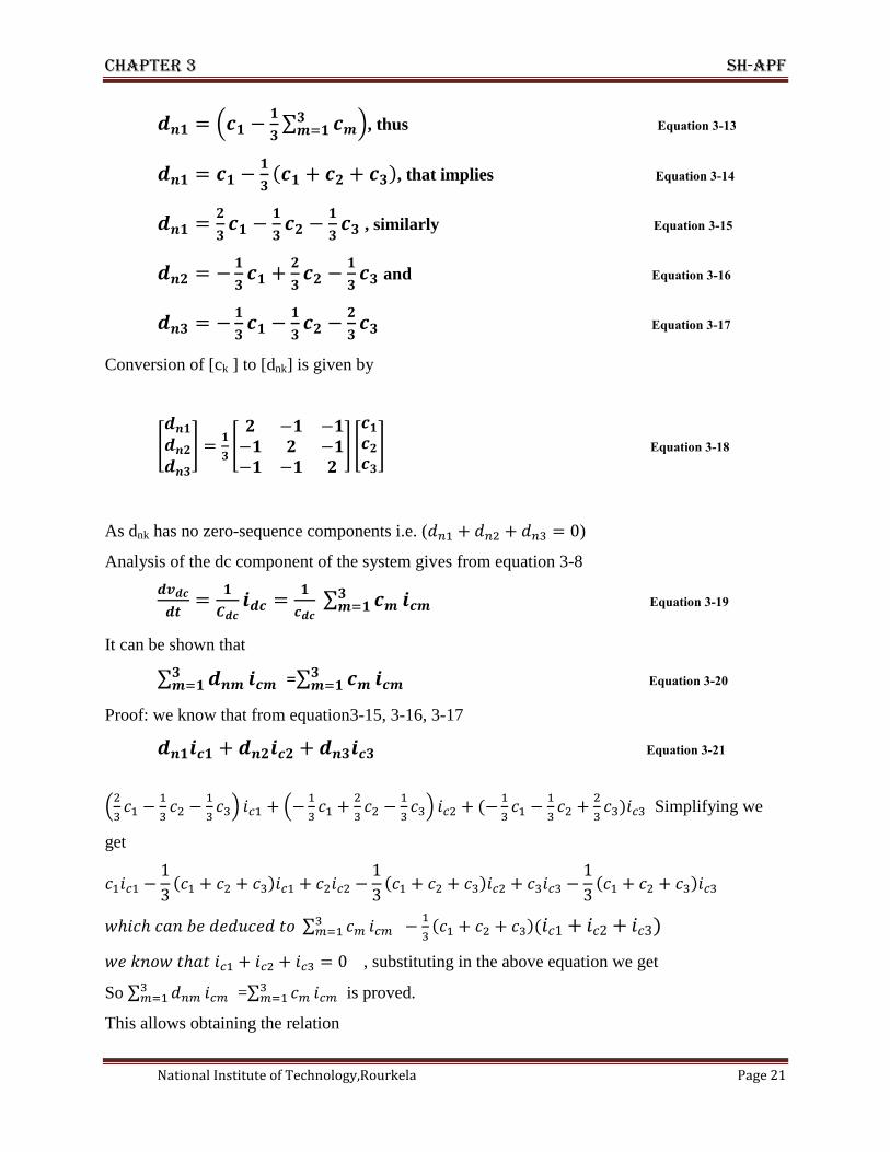
Chapter 3 SH-APF
National Institute of Technology,Rourkela Page 21
, thus Equation 3-13
, that implies Equation 3-14
, similarly Equation 3-15
and Equation 3-16
Equation 3-17
Conversion of [ck ] to [dnk] is given by
Equation 3-18
As dnk has no zero-sequence components i.e. ( )
Analysis of the dc component of the system gives from equation 3-8
Equation 3-19
It can be shown that
=
Equation 3-20
Proof: we know that from equation3-15, 3-16, 3-17
Equation 3-21
Simplifying we
get
, substituting in the above equation we get
So =
is proved.
This allows obtaining the relation
Chapter 3 SH-APF
National Institute of Technology,Rourkela Page 22
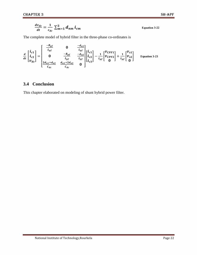
Equation 3-22
The complete model of hybrid filter in the three-phase co-ordinates is
Equation 3-23
3.4 Conclusion
This chapter elaborated on modeling of shunt hybrid power filter.

Chapter 4 PI controller
Page 23
CHAPTER-4
PI CONTROLLER
Introduction
Blocks used in control strategy
Modulation method
Harmonic detection block
Simulation
Conclusion

Chapter 4 PI controller
National Institute of Technology,Rourkela Page 24
4 Introduction
Proportional + Integral (PI) controllers were developed because of the desirable property that
systems with open loop transfer functions of type 1 or above have zero steady state error with
respect to a step input.
Figure 12: Block diagram of typical PI control
Control of a system based on hybrid active power filter denotes the close loop operation of the
system; it comprises of the elimination of errors in dc-link voltage control and generation of the
switching frequency for the active power filter switches. Actually the main aim of the control
strategy is to change the shape and value of compensating current as required; for that we have to
control the switching frequency. It again depends on the reference compensating current value
because it is the actual value of the harmonic content that the nonlinear load draws from the
source. The result of the operation of control system of an SH-APF is harmonic free sinusoidal
source current which is desired.

Chapter 4 PI controller
National Institute of Technology,Rourkela Page 25
4.1 Blocks describing control strategy In Fig.13 the three phase supply currents Is1 , Is2, Is3 are measured and transformed into
synchronous reference frame (d-q) axes rotating at the fundamental angular speed. Power p and q
contain two components i.e. dc and ac. A dc components arising from the fundamental
component of the source current, and an ac component due to its harmonic components. The ac
components idh, iqh are extracted by two high pass filters and then, the harmonic component of
the source current are obtained by applying the inverse transformation. To provide the inverter
power losses and to maintain the DC voltage with in desired value, a dc component PLoss is
added to the ac component of the imaginary power. It is generated by comparing the DC
capacitor voltage with its reference value and applying the error to a P-I controller. To generate
the required voltage command for the active filter inverter a d-q to a-b-c transformation is
applied to convert the inverter voltage command back to the three phase quantities.
Figure 13 System diagram for three phase SH-APF topology

Chapter 4 PI controller
National Institute of Technology,Rourkela Page 26
4.2 A-B-C to d-q transformation
Some time it is mistaken that three-phase system is combination of three separate single phase
system; but in reality three phase system is different from three combined single phase circuit.
Simply the load current in single phase system is square wave but in case of three phase system it is
quasi square wave. There are other issues are there in terms of circulating current, zero sequence
current, neutral current which are not present in a single phase system. In case of an active filter also
the control strategy is different from the single phase active power filter. Mainly the harmonic
detection part is different from the single phase filter. There are several methods of harmonic
detection. We can do it for separate phases also but the total control circuit will be complex, because
it will require more filters and separate control circuit. So from all methods two methods attains
popularity due to its outstanding results. They are p-q method and id-iq method explained in next
section.
4.2.1 id-iq Method
In my strategy I have made use of d-q method. In electrical engineering direct-quadrature
transformation is a mathematical transformation used to simplify the analysis of three-phase
circuits. For balanced three-phase circuits application of the dqo transform reduces the three AC
quantities to two DC quantities obviously in terms of current. Simplified calculations can then be
carried out on these imaginary DC quantities before performing the inverse transform to recover
the actual three-phase AC results. Again it is often used in order to simplify the analysis of three-
phase synchronous machines or to simplify calculations for the control of three-phase inverters.
Formula for abc to dq transformation
Id=2/3[(Ia sinwt+ I b sin(wt-2π/3))+ I c sin(wt+2π/3)] Equation 4-1
Iq=2/3[(Ia coswt+ I b cos(wt-2π/3))+I c cos(wt+2π/3)] Equation 4-2
Formula for dq to abc transformation
Ia= Id coswt - Iq sinwt Equation 4-3
I b= Id cos(wt-2π/3) - Iq sin(wt-2π/3) Equation 4-4
I c= Id cos(wt+2π/3) - Iq sin(wt+2π/3) Equation 4-5
Chapter 4 PI controller
National Institute of Technology,Rourkela Page 27
The resulting transformed model in the synchronous orthogonal rotating frame is as follows:
Correlating from equations 3-1 to 3-7 we get
Equation 4-6
Equation 4-7
Equation 4-8
Equation 4-9
Equation 4-10
For detection of harmonics instantaneous active and reactive load currents and can also be
decomposed into oscillatory and average terms and the first harmonic current of positive
sequence is transformed to dc quantities, , i.e., this constitutes the average current components.
All higher order current harmonics including the first harmonic current of negative sequence,
are transformed to non-dc quantities and undergo a frequency shift in the spectra and so
constitute the oscillatory current components. These assumptions are valid under balanced and
sinusoidal mains voltage conditions.
Eliminating the average current components by LPF’s the currents that should be
compensated are obtained and reference compensating current is obtained with the help of
transformation in equations (5-5 to 5-10).
4.3 MODULATION METHOD
The used modulation method is the conventional method because the switching is not given in
continuous manner. It totally depends upon the reference compensating current. Fig. 14
illustrates the conventional modulation methodology.
Hysteretic current control method is advanced for its simplicity of implementation,
good dynamic performance, fix tolerance range, peak current protection, small affection of
the mains voltage and excellent stability. But the variable switching frequency makes the
switching ripple current not easily filtered, introducing the switching noise to the power grid.
Moreover, the variable switching frequency will make the power switch uncontrolled in the

Chapter 4 PI controller
National Institute of Technology,Rourkela Page 28
large power application. Furthermore, the unequal current pulse will break to the “ampere-
second balance” of the capacitor, resulting in the unbalance of the dc-link capacitor in the
SH-APF topology. Therefore, the control method of SH-APF is based on the triangle-wave
current modulation control.
Figure 14: PWM technique
4.4 Harmonic detection and Logic circuit block
By the inverse Park transformation the first harmonic load current of positive sequence is
transformed to dc quantities, these represent the harmonic current system that must be preserved
in the mains. The ac components of the load current must be injected by the AF. These ac
quantities are which derive from the load currents through the SH-APF, Low-pass -order filters
are used. The cutoff frequency chosen is f/2. This assures a small phase shift in harmonics and a
sufficiently fast transient response in the AF harmonic compensation. As stated before in Section
the fourth-order APF gives the best performance.

Chapter 4 PI controller
National Institute of Technology,Rourkela Page 29
Figure 15: Reference compensating current generation circuit
Fig. 15 gives the schematic idea of the harmonic detection block; dc link voltage and load current are
input to the block and reference current is the output. Fig. 16 gives the internal circuit of the
harmonic detection block.
Figure 16: Logic circuit and internal circuit
Shunt active power filters have been employed in order to eliminate current harmonics and to
compensate reactive power. Dc-link voltage of the filter should be controlled in order to supply the
power losses of filter on the grid, providing that more effective filtering and reactive power

Chapter 4 PI controller
National Institute of Technology,Rourkela Page 30
compensation are obtained. So to obtain constant performance dc- link voltage should be constant.
The error signal of dc link voltage and reference voltage is given to the PI controller. The main work
of PI controller is to minimize the error and to make the dc link voltage constant
Harmonics are present in load current. The fundamental component of load current is the source
current; compensating current is the difference between the source current and the load current.
That’s why load current is passed through the low pass filter to filter out the fundamental current.
This fundamental load current subtracted from the actual load current which gives the harmonic
current. The filter is taken here is fourth order low pass Butterworth filter. The cut off frequency is
taken simply the fundamental frequency so as to pass the fundamental component of load current.
Harmonic current is then inserted into the voltage control circuit. By comparing the output of PI
controller and harmonic current reference compensating current is generated.
A proportional integral (PI) controller with anti-windup performs the voltage regulation on the
VSC dc side. Its input is the capacitor voltage error. Through regulation of the first dc Voltage
Regulation harmonic direct current of positive sequence it is possible to control the active power
flow in the VSC and thus the capacitor voltage.
The final drive signal Q1 and Q2 will be obtained with Q and low-frequency polarity signal q. Q2 will
be obtained by using “and” operation of Q and q; and Q1 will be obtained by using “and” operation of
invert signal of q and Q. As shown in Fig. 3.5 this operation is done by the logic and drive circuit.
4.5 Results and discussion using PI control strategy
The shunt hybrid power filter which is connected to a voltage source type non-linear load is
simulated by using MATLAB/SIMULINK environment. The scheme is first simulated without
any filter to find out the THD of the supply current. Then it is simulated with the hybrid filter to
observe the difference in THD of supply current. Simulation is also carried P-I controller to find
out the comparative study of the THD of the supply current.

Chapter 4 PI controller
National Institute of Technology,Rourkela Page 31
4.6 Simulation without any filter
Figure 17: source voltage
Figure 18:Load current
Figure 19:Source current
0.38 0.385 0.39 0.395 0.4
-200
0
200
Time(sec)
Vo
lta
ge
(Vo
lts)
0 0.05 0.1 0.15 0.2 0.25 0.3 0.35 0.4
-20
0
20
Time(sec)
Cu
rre
nt(
Am
p)
0 0.05 0.1 0.15 0.2 0.25 0.3 0.35 0.4
-20
0
20
Time(se )
Cu
rre
nt(
Am
p)

Chapter 4 PI controller
National Institute of Technology,Rourkela Page 32
4.7 Similation with Passive Shunt Filter and PI control
Figure 20: Load Current
Figure 21: Load current
Figure 22: Source current without control
0.38 0.385 0.39 0.395 0.4-35
0
35
Time(sec)
Cu
rre
nt(
Am
p)
0.38 0.385 0.39 0.395 0.4-35
0
35
Time(sec)
Cu
rre
nt(
Am
p)
0 0.05 0.1 0.15 0.2 0.25 0.3 0.35 0.4-20
0
20
Time(sec)
Cu
rre
nt(
Am
p)

Chapter 4 PI controller
National Institute of Technology,Rourkela Page 33
Figure 23:compensating current
Figure 24: Source voltage
Figure 25: Source current after compensation and control
0 0.05 0.1 0.15 0.2 0.25 0.3 0.35 0.4-20
0
20
Time(sec)
Cu
rre
nt(
Am
p)
0.38 0.385 0.39 0.395 0.4
-200
0
200
Time(sec)
Vo
lta
ge
(Vo
lts)
0.38 0.385 0.39 0.395 0.4-20
0
20
Time(sec)
Cu
rre
nt(
Am
p)

Chapter 4 PI controller
National Institute of Technology,Rourkela Page 34
Figure 26: Source current in single phase after compensation
Figure 27:DC-LINK Voltage
4.8 Conclusion
The detailed block diagram of control strategy has been explained starting with abc-dq
transform and its inverse transform, the harmonic detection block, the modulation technique and
the logical drive circuit has been discussed. The matlab simulations for the control strategy is
carried out and the results have been potrayed.It has been observed that with PI control the
compensation performance is increasing.
0.38 0.385 0.39 0.395 0.4-20
0
20
Time(sec)
Cu
rre
nt(
Am
p)
0.25 0.3 0.35 0.4380
400
420
Time(sec)
DC
-lin
k V
olta
ge
(Vo
lts)

Chapter-5 Lyapunov control
Page 35
CHAPTER-5
LYAPUNOV CONTROL
Introduction
Simulation
Comparison of THD’s
Conclusion

Chapter 5 Lyapunov Control
National Institute of Technology,Rourkela Page 36
5 Introduction
Any model of a real system presents inaccuracies. This is the reason why robustness with respect
to system variations is perhaps one of the most important aspects in the analysis and control of
dynamical systems. In simple words, a system which has to guarantee certain properties is said
robust if satisfies the requirements not only for its nominal values but also in the presence of
perturbations. In this survey we present an overview of a specific approach to system robustness
and precisely that based on the Lyapunov theory. Although this approach is a classical one, it is
still of great interest in view of the powerful tools it considers. We first introduce some generic
concepts related to the theory of Lyapunov Functions and Control Lyapunov Functions. Then we
simulate the control strategy.
Figure 28:LYAPUNOV control strategy
Buy SmartDraw!- purchased copies print this
document without a watermark .
Visit www.smartdraw.com or call 1-800-768-3729.

Chapter 5 Lyapunov Control
National Institute of Technology,Rourkela Page 37
5.1 SIMULATION
The shunt hybrid power filter which is connected to a voltage source type non-linear load is
simulated by using MATLAB/SIMULINK environment. The scheme is first simulated without
any filter to find out the THD of the supply current. Then it is simulated with the hybrid filter to
observe the difference in THD of supply current. Simulation is also carried Lyapunov controller
to find out the comparative study of the THD of the supply current.
5.2 Simulation using Passive shunt filter and Lyapunov control
Figure 29: Load current
Figure 30:Load current in single phase
Figure 31:Source voltage
0.38 0.385 0.39 0.395 0.4-35
0
35
Time(sec)
Cu
rre
nt(
Am
p)
0.38 0.385 0.39 0.395 0.4-35
0
35
Time(sec)
Cur
rent
(Am
p)
0.38 0.385 0.39 0.395 0.4
-200
0
200
Time(sec)
Vo
lta
ge
(Vo
lts)

Chapter 5 Lyapunov Control
National Institute of Technology,Rourkela Page 38
Figure 32: Source current
Figure 33:Source current in single phase
Figure 34: Source current after compensation
0 0.05 0.1 0.15 0.2 0.25 0.3 0.35 0.4
-20
-10
0
10
20
Time(sec)
Cu
rre
nt(
Am
p)
0.05 0.1 0.15 0.2 0.25 0.3 0.35 0.4
-20
-10
0
10
20
Time(sec)
Cu
rre
nt(
Am
p)
0 0.02 0.04 0.06 0.08 0.1 0.12 0.14 0.16
-20
-10
0
10
20
Time(sec)
Cu
rre
nt(
Am
p)

Chapter 5 Lyapunov Control
National Institute of Technology,Rourkela Page 39
Figure 35:Source current after compensation in single phase
Figure 36: DC-LINK Voltage
0 0.02 0.04 0.06 0.08 0.1 0.12 0.14 0.16
-20
-10
0
10
20
Time(sec)
Cu
rre
nt(
Am
p)
0.25 0.3 0.35 0.450
55
60
Time(sec)
DC
-lin
k V
olta
ge
(V
olts)

Chapter 5 Lyapunov Control
National Institute of Technology,Rourkela Page 40
5.3 Comparison of THD’s
Figure 37:THD without any filter
Figure 38:THD with PASSIVE-SHUNT and PI Controller
0 200 400 600 800 10000
50
100
Frequency (Hz)
Fundamental (50Hz) = 92.26 , THD= 3.95%
Ma
g (
% o
f F
un
da
me
nta
l)
0 200 400 600 800 10000
50
100
Frequency (Hz)
Fundamental (50Hz) = 0.5342 , THD= 14.69%
Ma
g (
% o
f F
un
da
me
nta
l)
Chapter 5 Lyapunov Control
National Institute of Technology,Rourkela Page 41
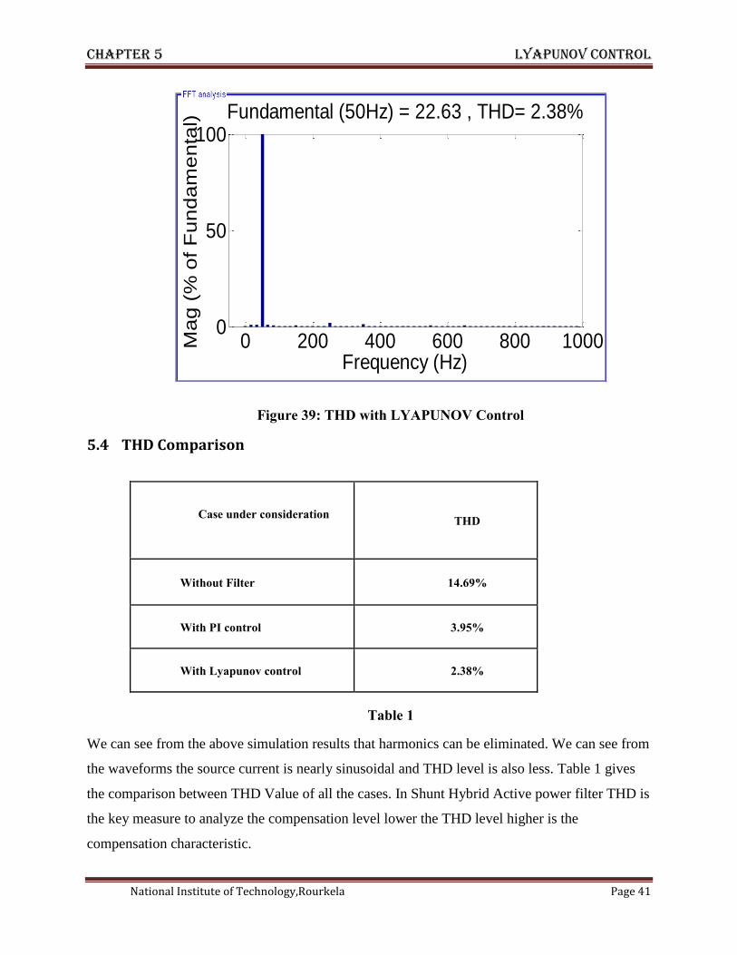
Figure 39: THD with LYAPUNOV Control
5.4 THD Comparison
Case under consideration
THD
Without Filter 14.69%
With PI control 3.95%
With Lyapunov control 2.38%
Table 1
We can see from the above simulation results that harmonics can be eliminated. We can see from
the waveforms the source current is nearly sinusoidal and THD level is also less. Table 1 gives
the comparison between THD Value of all the cases. In Shunt Hybrid Active power filter THD is
the key measure to analyze the compensation level lower the THD level higher is the
compensation characteristic.
0 200 400 600 800 10000
50
100
Frequency (Hz)
Fundamental (50Hz) = 22.63 , THD= 2.38%
Ma
g (
% o
f F
un
da
me
nta
l)

Chapter 6 conclusion
Page 42
CHAPTER-6
CONCLUSION
Conclusion
Suggestion for future work

Chapter 7 conclusion
National Institute of Technology,Rourkela Page 43
6 Conclusion
Nowadays, reliability and quality of electric power is one of the most discussed topics in power
industry. Numerous types of power quality issues and power problems and each of them might
have varying and diverse causes.
Harmonic pollution is one of the attention seeking problems. It leads to several losses and
destroys the quality of the power. To overcome these entire problems power filter is one of the
best solutions. Shunt Hybrid Active power filter has so many advantages over conventional
filters so on today scenario Shunt active power filter used mostly to eliminate harmonics from
the power system.
During this part of project work different types of hybrid filters is studied and analyzed. Filtering
characteristics of different control strategies are analyzed and compared based on system model.
A dc-voltage control loop is also designed with traditional PI regulator. The SH-APF employing
the proposed Lyapunov-function based control strategy has been found suitable for voltage and
current source type non-linear loads.
The obtained results have demonstrated the high performance level of SH-APF.Hence, the SH-
APF system can be an effective and economic solution for harmonic problems caused by non-
linear loads.
6.1 Major contribution
o Studying different Hybrid filter configurations.
o Designing SH-APF with PI control strategy
o Designing SH-APF with LYAPUNOV control strategy
o Comparing the THD’s of each control strategy
6.2 Scope for Future work
Shunt Hybrid Active Power filter can be designed using various cascade topologies
which will help to compensate harmonics in various types of nonlinear loads.
Various combination of Hybrid filters can be used for compensation of harmonics.
The control strategy can be improved by applying fuzzy logic control.
Chapter 7 References
Page 44
7 REFERENCES
[1]. Roger C. Dugan, Mark F. McGranaghan and H. Wayne Beaty, TK1001.D84 (1996)
“Electrical Power Systems Quality”, Mc Graw-Hill. Pages 1-8 and 39-80.
[2]. F. Z. Peng, “Harmonic sources and filtering approaches,” IEEE Ind. Appl Mag., vol. 7, no. 4,
pp. 18–25, Jul./Aug. 2001.
[3]. B. Singh, V. Verma, A. Chandra, and K. Al-Haddad, “Hybrid filters for power quality
improvement,” Proc. Inst. Elect. Eng.Gener.Transm. Distrib, vol. 152, no. 3, pp. 365–378,
May 2005.
[4]. A. Hamadi, S. Rahmani, and K. Al-Haddad, “A hybrid passive filter configuration for VAR
control and harmonic compensation,” IEEE Trans.Ind. Electron.vol. 57, no. 7, pp. 2419–2434
Jul. 2010.
[5]. S. Ostroznik, P. Bajec, and P. Zajec, “A study of a hybrid filter,” IEEE Trans. Ind. Electron.
vol. 57, no. 3, pp. 935–942, Mar. 2010.
[6]. S. Rahmani, A. Hamadi, N. Mendalek, and K. Al-Haddad, “A new control technique for
three-phase shunt hybrid power filter,” IEEE Trans. Ind Electron., vol. 56, no. 8, pp. 2904–
2915, Aug. 2009.
[7]. C. Sankaran, 21-dec-2001. “Power quality”, CRC Press, Page 1-9.
[8]. IEE Std. 519-1992, “IEEE recommended practices and requirements for harmonic control in
electrical power system”, IEE April12, 1993
[9]. Amoli M. E. and Florence T., “Voltage, current harmonic content of a utility system-A
summary of 1120 test measurements,” IEEE Trans. Power Delivery, vol. 5, (1990):pp. 1552–
1557.
[10]. “Harmonic guide”, www.controltechniques.com. Control technique 2000, part no. 0400-
0078-08700.
[11]. M. Rahmani, A. Arora, R. Pfister, P. Huencho, “State of the Art Power Quality Devices
and Innovative Concepts”, in VII Seminario de Electrónica de Potencia, Valparaíso, Chile,
Abril 1999.
[12]. J. S. Subjek, J. S. Mcquilkin, Harmonics-causes, effects, measurements and analysis,
IEEE Trans. Ind. Appl. 26 (November/December (6)) (1990) 1034-1041.
[13]. Tavakoli Bina. M. , Pashajavid. E., “An efficient procedure to design passive LCLfilters
for active power filters”, © 2008 Elsevier B.V, 2008, doi 10.1016/j. epsr.2008.08.014, pp.
606– 614.
Chapter 7references
National Institute of Technology,Rourkela Page 45
[14]. L. Gyugyi and E. Strycula, “Active ac power filter,” ZEEE Trans. Industry Applications,
pp. 529-535, 1976
[15]. H. Akagi, “New Trends in Active Filters for Power Conditioning,” in IEEE Trans. on
Industry Applications, vol. 32, no. 6, pp. 1312-1322, Nov./Dec. 1996.
[16]. H. Akagi, A. Nahae, and S. Atoh, “Control strategy of active power filters using voltage-
source PWM converters,” ZEEE Trans. Zndustry Applications, vol. IA-22, no. 3, p. 460,
1986
[17]. L. Morán, L. Fernández, J. Dixon, R. Wallace, “A Simple and Low Cost Control
Strategy for Active Power Filters Connected in Cascade”, in IEEE Trans. on Industrial
Electronics, vol. 44, no. 5, pp.621-629, Oct. 1997.
[18]. H. Akagi, S. Srianthumrong, Y. Tamai, “Comparisons in Circuit Configuration
Performance between Hybrid and Pure Shunt Active Filters”, in Conf. Rec. IEEE-IAS Annu.
Meeting, vol: 2, 2003, pp. 1195–1202
[19]. R. Inzunza, H. Akagi, “A 6.6kV Transformer less Shunt Hybrid Active Filter for
Installation on a Power Distribution System”, IEEE transactions on power Electronics, Vol.
20, No. 4, July 2005, pp. 893-900
[20]. N. He, D. Xu, and L. Huang, “The application of particle swarm opti- mization to passive
and hybrid active power filter design,” IEEE Trans.Ind. Electron., vol. 56, no. 8, pp. 2841–2851,
Aug. 2009.
[21]. S. Rahmani, N. Mendalek, and K. Al-Haddad, “Experimental design of a nonlinear
control technique for three-phase shunt active power filter,”IEEE Trans. Ind. Electron., vol. 57,
no. 10, pp. 3364–3375, Oct. 2010.
[22]. A. Luo, X. Xu, L. Fang, H. Fang, J. Wu, and C. Wu, “Feedback- feedforward PI-type
iterative learning control strategy for hybrid active power filter with injection circuit,” IEEE
Trans. Ind. Electron., vol. 57,no. 11, pp. 3767–3779, Nov. 2010.


