Embed Size (px)
Citation preview
IBM
TotalStorage
SAN
Switch
2109
Model
M12
and
Model
M14
User’s
Guide
GC26-7636-00
Read
Before
Using
This
product
contains
software
that
is
licensed
under
written
license
agreements.
Your
use
of
such
software
is
subject
to
the
license
agreements
under
which
they
are
provided.
���

IBM
TotalStorage
SAN
Switch
2109
Model
M12
and
Model
M14
User’s
Guide
GC26-7636-00
���

Note:
Before
using
this
information
and
the
product
it
supports,
read
the
information
in
“Notices”
on
page
39.
First
Edition
(May
2004)
This
publication
replaces
the
IBM
TotalStorage
SAN
Switch
2109
Model
M12
user’s
Guide
(GC26–7468).
The
following
paragraph
does
not
apply
to
any
country
(or
region)
where
such
provisions
are
inconsistent
with
local
law.
INTERNATIONAL
BUSINESS
MACHINES
CORPORATION
PROVIDES
THIS
PUBLICATION
“AS
IS”
WITHOUT
WARRANTY
OF
ANY
KIND,
EITHER
EXPRESS
OR
IMPLIED,
INCLUDING,
BUT
NOT
LIMITED
TO,
THE
IMPLIED
WARRANTIES
OF
MERCHANTABILITY
OR
FITNESS
FOR
A
PARTICULAR
PURPOSE.
Some
states
(or
regions)
do
not
allow
disclaimer
of
express
or
implied
warranties
in
certain
transactions;
therefore,
this
statement
may
not
apply
to
you.
Order
publications
through
your
IBM
representative
or
the
IBM
branch
office
serving
your
locality.
©
Copyright
International
Business
Machines
Corporation
2004.
All
rights
reserved.
US
Government
Users
Restricted
Rights
–
Use,
duplication
or
disclosure
restricted
by
GSA
ADP
Schedule
Contract
with
IBM
Corp.
Contents
Figures
.
.
.
.
.
.
.
.
.
.
.
.
.
.
.
.
.
.
.
.
.
.
.
.
.
.
. vii
Tables
.
.
.
.
.
.
.
.
.
.
.
.
.
.
.
.
.
.
.
.
.
.
.
.
.
.
.
. ix
Safety
and
environmental
notices
.
.
.
.
.
.
.
.
.
.
.
.
.
.
.
.
. xi
Safety
notices
and
labels
.
.
.
.
.
.
.
.
.
.
.
.
.
.
.
.
.
.
.
.
. xi
Danger
notices
.
.
.
.
.
.
.
.
.
.
.
.
.
.
.
.
.
.
.
.
.
.
.
. xi
Labels
.
.
.
.
.
.
.
.
.
.
.
.
.
.
.
.
.
.
.
.
.
.
.
.
.
.
. xiii
Caution
notices
.
.
.
.
.
.
.
.
.
.
.
.
.
.
.
.
.
.
.
.
.
.
.
. xiii
Attention
notices
.
.
.
.
.
.
.
.
.
.
.
.
.
.
.
.
.
.
.
.
.
.
. xiv
Safety
inspections,
installations,
and
service
.
.
.
.
.
.
.
.
.
.
.
.
.
. xiv
Laser
safety
.
.
.
.
.
.
.
.
.
.
.
.
.
.
.
.
.
.
.
.
.
.
.
.
.
. xiv
Usage
restrictions
.
.
.
.
.
.
.
.
.
.
.
.
.
.
.
.
.
.
.
.
.
.
. xiv
Environmental
notices
and
statements
.
.
.
.
.
.
.
.
.
.
.
.
.
.
.
. xv
Battery
notice
.
.
.
.
.
.
.
.
.
.
.
.
.
.
.
.
.
.
.
.
.
.
.
. xv
Fire
suppression
systems
.
.
.
.
.
.
.
.
.
.
.
.
.
.
.
.
.
.
.
. xv
Product
recycling
.
.
.
.
.
.
.
.
.
.
.
.
.
.
.
.
.
.
.
.
.
.
. xv
Product
disposal
.
.
.
.
.
.
.
.
.
.
.
.
.
.
.
.
.
.
.
.
.
.
. xv
About
this
document
.
.
.
.
.
.
.
.
.
.
.
.
.
.
.
.
.
.
.
.
. xvii
Who
should
read
this
document
.
.
.
.
.
.
.
.
.
.
.
.
.
.
.
.
.
. xvii
Model
M12
and
M14
library
.
.
.
.
.
.
.
.
.
.
.
.
.
.
.
.
.
.
.
. xvii
Related
documents
.
.
.
.
.
.
.
.
.
.
.
.
.
.
.
.
.
.
.
.
.
.
. xvii
Web
sites
.
.
.
.
.
.
.
.
.
.
.
.
.
.
.
.
.
.
.
.
.
.
.
.
.
. xviii
Getting
software
updates
.
.
.
.
.
.
.
.
.
.
.
.
.
.
.
.
.
.
.
.
. xviii
Getting
help
.
.
.
.
.
.
.
.
.
.
.
.
.
.
.
.
.
.
.
.
.
.
.
.
.
. xix
How
to
send
your
comments
.
.
.
.
.
.
.
.
.
.
.
.
.
.
.
.
.
.
.
. xix
Chapter
1.
Introduction
.
.
.
.
.
.
.
.
.
.
.
.
.
.
.
.
.
.
.
.
.
. 1
Product
overview
.
.
.
.
.
.
.
.
.
.
.
.
.
.
.
.
.
.
.
.
.
.
.
. 1
Throughput
.
.
.
.
.
.
.
.
.
.
.
.
.
.
.
.
.
.
.
.
.
.
.
.
.
. 2
Link
distance
.
.
.
.
.
.
.
.
.
.
.
.
.
.
.
.
.
.
.
.
.
.
.
.
. 2
SFP
fiber
optic
transceivers
.
.
.
.
.
.
.
.
.
.
.
.
.
.
.
.
.
.
.
. 2
Chapter
2.
System
design
overview
.
.
.
.
.
.
.
.
.
.
.
.
.
.
.
.
. 3
High
Availability
.
.
.
.
.
.
.
.
.
.
.
.
.
.
.
.
.
.
.
.
.
.
.
.
. 5
Reliability
.
.
.
.
.
.
.
.
.
.
.
.
.
.
.
.
.
.
.
.
.
.
.
.
.
.
. 6
Serviceability
.
.
.
.
.
.
.
.
.
.
.
.
.
.
.
.
.
.
.
.
.
.
.
.
.
. 6
Hot-swappable
FRUs
.
.
.
.
.
.
.
.
.
.
.
.
.
.
.
.
.
.
.
.
.
. 7
Ports
.
.
.
.
.
.
.
.
.
.
.
.
.
.
.
.
.
.
.
.
.
.
.
.
.
.
.
.
. 7
Optical
ports
.
.
.
.
.
.
.
.
.
.
.
.
.
.
.
.
.
.
.
.
.
.
.
.
. 7
Ethernet
port
.
.
.
.
.
.
.
.
.
.
.
.
.
.
.
.
.
.
.
.
.
.
.
.
. 8
Serial
port
.
.
.
.
.
.
.
.
.
.
.
.
.
.
.
.
.
.
.
.
.
.
.
.
.
. 8
Numbering
.
.
.
.
.
.
.
.
.
.
.
.
.
.
.
.
.
.
.
.
.
.
.
.
.
.
. 8
Rack
mounting
.
.
.
.
.
.
.
.
.
.
.
.
.
.
.
.
.
.
.
.
.
.
.
.
. 8
Cooling
system
.
.
.
.
.
.
.
.
.
.
.
.
.
.
.
.
.
.
.
.
.
.
.
.
. 8
Cable
management
.
.
.
.
.
.
.
.
.
.
.
.
.
.
.
.
.
.
.
.
.
.
.
. 9
Worldwide
name
LED
card
.
.
.
.
.
.
.
.
.
.
.
.
.
.
.
.
.
.
.
.
. 9
Chapter
3.
Power
distribution
system
.
.
.
.
.
.
.
.
.
.
.
.
.
.
.
. 11
Power
distribution
strategy
.
.
.
.
.
.
.
.
.
.
.
.
.
.
.
.
.
.
.
.
. 11
AC
input
.
.
.
.
.
.
.
.
.
.
.
.
.
.
.
.
.
.
.
.
.
.
.
.
.
. 11
DC
outputs
.
.
.
.
.
.
.
.
.
.
.
.
.
.
.
.
.
.
.
.
.
.
.
.
. 11
©
Copyright
IBM
Corp.
2004
iii
2N
power
architecture
.
.
.
.
.
.
.
.
.
.
.
.
.
.
.
.
.
.
.
.
. 12
Chapter
4.
CP
blades
and
16-port
blades
.
.
.
.
.
.
.
.
.
.
.
.
.
. 13
CP
blade
assembly
.
.
.
.
.
.
.
.
.
.
.
.
.
.
.
.
.
.
.
.
.
.
. 14
CPU
subsystem
.
.
.
.
.
.
.
.
.
.
.
.
.
.
.
.
.
.
.
.
.
.
. 15
Configuration
.
.
.
.
.
.
.
.
.
.
.
.
.
.
.
.
.
.
.
.
.
.
.
. 16
Management
.
.
.
.
.
.
.
.
.
.
.
.
.
.
.
.
.
.
.
.
.
.
.
.
. 16
Switch
blade
assembly
.
.
.
.
.
.
.
.
.
.
.
.
.
.
.
.
.
.
.
.
.
. 16
Switch
blade
assembly
design
.
.
.
.
.
.
.
.
.
.
.
.
.
.
.
.
.
. 17
Chapter
5.
Fault
monitoring
and
diagnostics
.
.
.
.
.
.
.
.
.
.
.
.
. 19
Diagnostic
tests
.
.
.
.
.
.
.
.
.
.
.
.
.
.
.
.
.
.
.
.
.
.
.
. 19
System
status
indicators
.
.
.
.
.
.
.
.
.
.
.
.
.
.
.
.
.
.
.
.
. 19
Cable-side
LEDs
.
.
.
.
.
.
.
.
.
.
.
.
.
.
.
.
.
.
.
.
.
.
. 19
Noncable
side
LEDs
.
.
.
.
.
.
.
.
.
.
.
.
.
.
.
.
.
.
.
.
.
. 20
Chapter
6.
Software
features
.
.
.
.
.
.
.
.
.
.
.
.
.
.
.
.
.
.
. 21
Fabric
OS
.
.
.
.
.
.
.
.
.
.
.
.
.
.
.
.
.
.
.
.
.
.
.
.
.
.
. 21
Fabric
OS
features
.
.
.
.
.
.
.
.
.
.
.
.
.
.
.
.
.
.
.
.
.
.
. 22
Interoperability
.
.
.
.
.
.
.
.
.
.
.
.
.
.
.
.
.
.
.
.
.
.
.
.
. 23
Security
.
.
.
.
.
.
.
.
.
.
.
.
.
.
.
.
.
.
.
.
.
.
.
.
.
.
. 23
Network
manageability
.
.
.
.
.
.
.
.
.
.
.
.
.
.
.
.
.
.
.
.
.
. 23
Chapter
7.
Field
replaceable
units
(FRUs)
.
.
.
.
.
.
.
.
.
.
.
.
.
. 25
Appendix
A.
Product
specifications
.
.
.
.
.
.
.
.
.
.
.
.
.
.
.
. 27
Model
M12
and
M14
components
.
.
.
.
.
.
.
.
.
.
.
.
.
.
.
.
.
. 27
Physical
dimensions
.
.
.
.
.
.
.
.
.
.
.
.
.
.
.
.
.
.
.
.
.
. 27
2109
Model
M12
and
component
weights
.
.
.
.
.
.
.
.
.
.
.
.
.
. 27
2109
Model
C36
with
M12
or
M14
specifications
.
.
.
.
.
.
.
.
.
.
.
. 28
16–port
card
specifications
.
.
.
.
.
.
.
.
.
.
.
.
.
.
.
.
.
.
. 28
CP
card
specifications
.
.
.
.
.
.
.
.
.
.
.
.
.
.
.
.
.
.
.
.
. 29
Facility
specifications
.
.
.
.
.
.
.
.
.
.
.
.
.
.
.
.
.
.
.
.
.
.
. 31
Power
specifications
.
.
.
.
.
.
.
.
.
.
.
.
.
.
.
.
.
.
.
.
.
.
. 31
Environmental
requirements
.
.
.
.
.
.
.
.
.
.
.
.
.
.
.
.
.
.
.
. 32
General
specifications
.
.
.
.
.
.
.
.
.
.
.
.
.
.
.
.
.
.
.
.
.
. 33
Regulatory
specifications
.
.
.
.
.
.
.
.
.
.
.
.
.
.
.
.
.
.
.
.
. 34
Appendix
B.
Safety
certifications
and
regulatory
compliance
.
.
.
.
.
. 37
Safety
.
.
.
.
.
.
.
.
.
.
.
.
.
.
.
.
.
.
.
.
.
.
.
.
.
.
.
. 37
EMI/EMC
.
.
.
.
.
.
.
.
.
.
.
.
.
.
.
.
.
.
.
.
.
.
.
.
.
.
. 37
Immunity
.
.
.
.
.
.
.
.
.
.
.
.
.
.
.
.
.
.
.
.
.
.
.
.
.
. 37
Notices
.
.
.
.
.
.
.
.
.
.
.
.
.
.
.
.
.
.
.
.
.
.
.
.
.
.
. 39
Trademarks
.
.
.
.
.
.
.
.
.
.
.
.
.
.
.
.
.
.
.
.
.
.
.
.
.
. 40
Electronic
emission
notices
.
.
.
.
.
.
.
.
.
.
.
.
.
.
.
.
.
.
.
. 40
Federal
Communications
Commission
(FCC)
Class
A
Statement
.
.
.
.
. 40
Industry
Canada
Class
A
Emission
Compliance
Statement
.
.
.
.
.
.
.
. 40
Avis
de
conformité
à
la
réglementation
d’Industrie
Canada
.
.
.
.
.
.
.
. 40
European
Union
(EU)
Electromagnetic
Compatibility
Directive
.
.
.
.
.
.
. 40
Germany
Electromagnetic
Compatibility
Directive
.
.
.
.
.
.
.
.
.
.
. 41
Chinese
Class
A
Electronic
Emission
Statement
.
.
.
.
.
.
.
.
.
.
.
. 41
Taiwan
Class
A
Electronic
Emission
Statement
.
.
.
.
.
.
.
.
.
.
.
. 42
Japan
VCCI
Class
A
ITE
Electronic
Emission
Statement
.
.
.
.
.
.
.
.
. 42
Glossary
.
.
.
.
.
.
.
.
.
.
.
.
.
.
.
.
.
.
.
.
.
.
.
.
.
.
. 43
iv
IBM
TotalStorage
SAN
Switch:
2109
Model
M12
and
Model
M14
User’s
Guide

Index
.
.
.
.
.
.
.
.
.
.
.
.
.
.
.
.
.
.
.
.
.
.
.
.
.
.
.
. 57
Contents
v

vi
IBM
TotalStorage
SAN
Switch:
2109
Model
M12
and
Model
M14
User’s
Guide

Figures
1.
Port
side
of
the
2109
Model
M12
.
.
.
.
.
.
.
.
.
.
.
.
.
.
.
.
.
.
.
.
.
.
.
.
. 3
2.
Port
side
of
the
2109
Model
M14
.
.
.
.
.
.
.
.
.
.
.
.
.
.
.
.
.
.
.
.
.
.
.
.
. 4
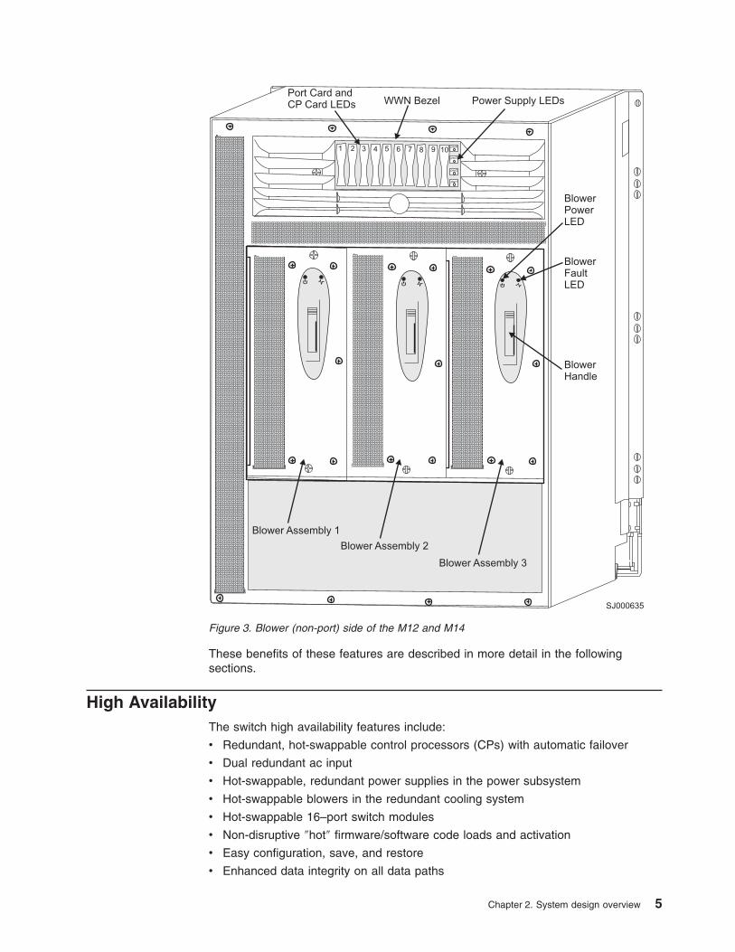
3.
Blower
(non-port)
side
of
the
M12
and
M14
.
.
.
.
.
.
.
.
.
.
.
.
.
.
.
.
.
.
.
.
. 5
4.
M12
16–port
card,
port
side
.
.
.
.
.
.
.
.
.
.
.
.
.
.
.
.
.
.
.
.
.
.
.
.
.
.
. 13
5.
M14
16–port
card,
port
side
.
.
.
.
.
.
.
.
.
.
.
.
.
.
.
.
.
.
.
.
.
.
.
.
.
.
. 14
©
Copyright
IBM
Corp.
2004
vii

viii
IBM
TotalStorage
SAN
Switch:
2109
Model
M12
and
Model
M14
User’s
Guide
Tables
1.
Brocade
and
IBM
product
and
model
number
matrix
.
.
.
.
.
.
.
.
.
.
.
.
.
.
.
.
. xviii
2.
Power
distribution
system
specifications
.
.
.
.
.
.
.
.
.
.
.
.
.
.
.
.
.
.
.
.
.
. 11
3.
Power
supply
configurations
.
.
.
.
.
.
.
.
.
.
.
.
.
.
.
.
.
.
.
.
.
.
.
.
.
.
. 12
4.
Cable
side
LEDs
.
.
.
.
.
.
.
.
.
.
.
.
.
.
.
.
.
.
.
.
.
.
.
.
.
.
.
.
.
.
. 19
5.
Noncable
side
LEDs
.
.
.
.
.
.
.
.
.
.
.
.
.
.
.
.
.
.
.
.
.
.
.
.
.
.
.
.
. 20
6.
Physical
dimensions
of
the
Model
M12
and
Model
M14
.
.
.
.
.
.
.
.
.
.
.
.
.
.
.
. 27
7.
Component
weights
.
.
.
.
.
.
.
.
.
.
.
.
.
.
.
.
.
.
.
.
.
.
.
.
.
.
.
.
.
. 27
8.
2109
Model
C36
with
Model
M12
or
M14
specifications
.
.
.
.
.
.
.
.
.
.
.
.
.
.
.
. 28
9.
Memory
specifications
.
.
.
.
.
.
.
.
.
.
.
.
.
.
.
.
.
.
.
.
.
.
.
.
.
.
.
.
. 29
10.
Battery
specifications
.
.
.
.
.
.
.
.
.
.
.
.
.
.
.
.
.
.
.
.
.
.
.
.
.
.
.
.
. 29
11.
Terminal
serial
port
pinouts
.
.
.
.
.
.
.
.
.
.
.
.
.
.
.
.
.
.
.
.
.
.
.
.
.
.
. 30
12.
Modem
serial
port
pinouts
.
.
.
.
.
.
.
.
.
.
.
.
.
.
.
.
.
.
.
.
.
.
.
.
.
.
. 30
13.
Power
specifications
.
.
.
.
.
.
.
.
.
.
.
.
.
.
.
.
.
.
.
.
.
.
.
.
.
.
.
.
. 31
14.
Power
specifications
.
.
.
.
.
.
.
.
.
.
.
.
.
.
.
.
.
.
.
.
.
.
.
.
.
.
.
.
. 32
15.
Environmental
requirements
.
.
.
.
.
.
.
.
.
.
.
.
.
.
.
.
.
.
.
.
.
.
.
.
.
.
. 32
16.
General
specifications
.
.
.
.
.
.
.
.
.
.
.
.
.
.
.
.
.
.
.
.
.
.
.
.
.
.
.
.
. 33
17.
Regulatory
specifications
.
.
.
.
.
.
.
.
.
.
.
.
.
.
.
.
.
.
.
.
.
.
.
.
.
.
.
. 34
©
Copyright
IBM
Corp.
2004
ix

x
IBM
TotalStorage
SAN
Switch:
2109
Model
M12
and
Model
M14
User’s
Guide
Safety
and
environmental
notices
This
section
contains
information
about:
v
“Safety
notices
and
labels”
v
“Safety
inspections,
installations,
and
service”
on
page
xiv
v
“Laser
safety”
on
page
xiv
v
“Environmental
notices
and
statements”
on
page
xv
Safety
notices
and
labels
When
using
this
product,
observe
the
danger,
caution,
and
attention
notices
contained
in
this
guide.
The
notices
are
accompanied
by
symbols
that
represent
the
severity
of
the
safety
condition.
The
danger
and
caution
notices
are
listed
in
numerical
order
based
on
their
IDs,
which
are
displayed
in
parentheses,
for
example
(D004),
at
the
end
of
each
notice.
Use
this
ID
to
locate
the
translation
of
these
danger
and
caution
notices
in
the
IBM®
eServer™
Safety
Notices
(G229–9054)
publication,
which
is
on
the
CD-ROM
that
accompanies
this
product.
See
the
following
examples
of
danger
and
caution
notices
for
the
location
of
the
ID
number.
Attention:
Inspections,
installations,
and
service
procedures
are
for
trained
service
personnel
only.
While
the
typical
operator
does
not
have
access
to
the
product
to
perform
inspections,
installations,
or
service,
the
following
comprehensive
danger
notice
provides
instructions
on
how
to
avoid
shock
hazards
when
working
with
such
equipment.
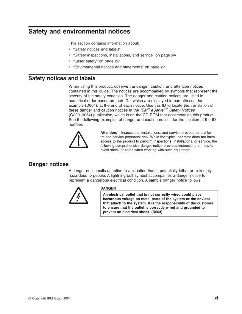
Danger
notices
A
danger
notice
calls
attention
to
a
situation
that
is
potentially
lethal
or
extremely
hazardous
to
people.
A
lightning
bolt
symbol
accompanies
a
danger
notice
to
represent
a
dangerous
electrical
condition.
A
sample
danger
notice
follows:
DANGER
An
electrical
outlet
that
is
not
correctly
wired
could
place
hazardous
voltage
on
metal
parts
of
the
system
or
the
devices
that
attach
to
the
system.
It
is
the
responsibility
of
the
customer
to
ensure
that
the
outlet
is
correctly
wired
and
grounded
to
prevent
an
electrical
shock.
(D004)
©
Copyright
IBM
Corp.
2004
xi
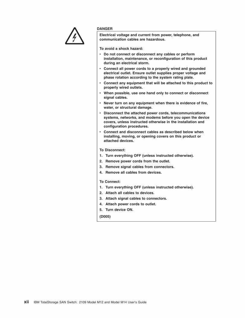
DANGER
Electrical
voltage
and
current
from
power,
telephone,
and
communication
cables
are
hazardous.
To
avoid
a
shock
hazard:
v
Do
not
connect
or
disconnect
any
cables
or
perform
installation,
maintenance,
or
reconfiguration
of
this
product
during
an
electrical
storm.
v
Connect
all
power
cords
to
a
properly
wired
and
grounded
electrical
outlet.
Ensure
outlet
supplies
proper
voltage
and
phase
rotation
according
to
the
system
rating
plate.
v
Connect
any
equipment
that
will
be
attached
to
this
product
to
properly
wired
outlets.
v
When
possible,
use
one
hand
only
to
connect
or
disconnect
signal
cables.
v
Never
turn
on
any
equipment
when
there
is
evidence
of
fire,
water,
or
structural
damage.
v
Disconnect
the
attached
power
cords,
telecommunications
systems,
networks,
and
modems
before
you
open
the
device
covers,
unless
instructed
otherwise
in
the
installation
and
configuration
procedures.
v
Connect
and
disconnect
cables
as
described
below
when
installing,
moving,
or
opening
covers
on
this
product
or
attached
devices.
To
Disconnect:
1.
Turn
everything
OFF
(unless
instructed
otherwise).
2.
Remove
power
cords
from
the
outlet.
3.
Remove
signal
cables
from
connectors.
4.
Remove
all
cables
from
devices.
To
Connect:
1.
Turn
everything
OFF
(unless
instructed
otherwise).
2.
Attach
all
cables
to
devices.
3.
Attach
signal
cables
to
connectors.
4.
Attach
power
cords
to
outlet.
5.
Turn
device
ON.
(D005)
xii
IBM
TotalStorage
SAN
Switch:
2109
Model
M12
and
Model
M14
User’s
Guide
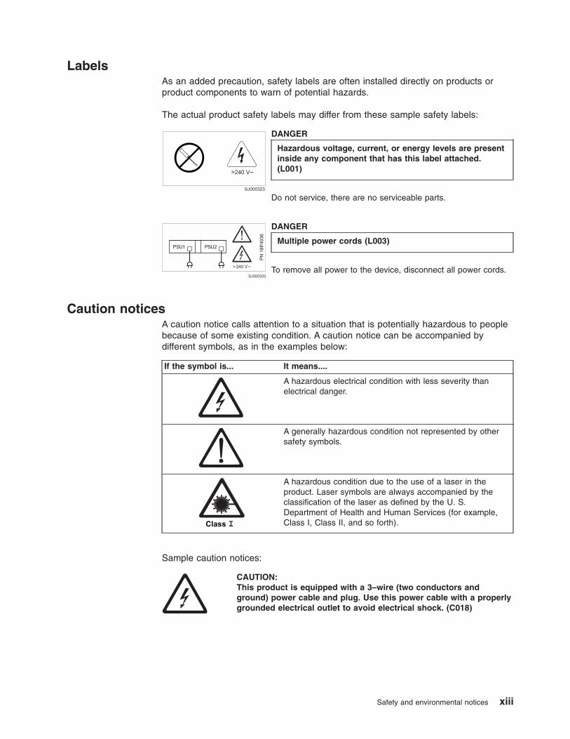
Labels
As
an
added
precaution,
safety
labels
are
often
installed
directly
on
products
or
product
components
to
warn
of
potential
hazards.
The
actual
product
safety
labels
may
differ
from
these
sample
safety
labels:
SJ000323
>240 V~
DANGER
Hazardous
voltage,
current,
or
energy
levels
are
present
inside
any
component
that
has
this
label
attached.
(L001)
Do
not
service,
there
are
no
serviceable
parts.
SJ000325
PN
18P
4036
>240 V~
PSU1 PSU2
DANGER
Multiple
power
cords
(L003)
To
remove
all
power
to
the
device,
disconnect
all
power
cords.
Caution
notices
A
caution
notice
calls
attention
to
a
situation
that
is
potentially
hazardous
to
people
because
of
some
existing
condition.
A
caution
notice
can
be
accompanied
by
different
symbols,
as
in
the
examples
below:
If
the
symbol
is...
It
means....
A
hazardous
electrical
condition
with
less
severity
than
electrical
danger.
A
generally
hazardous
condition
not
represented
by
other
safety
symbols.
A
hazardous
condition
due
to
the
use
of
a
laser
in
the
product.
Laser
symbols
are
always
accompanied
by
the
classification
of
the
laser
as
defined
by
the
U.
S.
Department
of
Health
and
Human
Services
(for
example,
Class
I,
Class
II,
and
so
forth).
Sample
caution
notices:
CAUTION:
This
product
is
equipped
with
a
3–wire
(two
conductors
and
ground)
power
cable
and
plug.
Use
this
power
cable
with
a
properly
grounded
electrical
outlet
to
avoid
electrical
shock.
(C018)
Safety
and
environmental
notices
xiii
CAUTION:
This
product
contains
a
Class
1M
laser.
Do
not
view
directly
with
optical
instruments.
(C028)
Attention
notices
An
attention
notice
indicates
the
possibility
of
damage
to
a
program,
device,
or
system,
or
to
data.
An
exclamation
point
symbol
may
accompany
an
attention
notice,
but
is
not
required.
A
sample
attention
notice
follows:
Attention:
Diagnostic
tests
can
temporarily
lock
the
transmit
and
receive
speed
of
the
links
during
diagnostic
testing.
Safety
inspections,
installations,
and
service
Attention:
A
typical
operator
does
not
have
access
to
the
product
to
perform
inspections,
installations,
or
service.
Detailed
safety
instructions
for
installation,
inspection,
and
service
are
located
in
the
specific
installation
and
service
guides.
The
procedures
contained
in
those
publications
are
for
trained
service
personnel
only.
Laser
safety
This
equipment
contains
Class
1
laser
products,
and
complies
with
FDA
radiation
Performance
Standards,
21
CFR
Subchapter
J
and
the
international
laser
safety
standard
IEC
825-2.
CAUTION:
This
product
contains
a
Class
1M
laser.
Do
not
view
directly
with
optical
instruments.
(C028)
Attention:
In
the
United
States,
use
only
SFP
or
GBIC
optical
transceivers
that
comply
with
the
FDA
radiation
performance
standards,
21
CFR
Subchapter
J.
Internationally,
use
only
SFP
or
GBIC
optical
transceivers
that
comply
with
IEC
standard
825–1.
Optical
products
that
do
not
comply
with
these
standards
may
product
light
that
is
hazardous
to
the
eyes.
Usage
restrictions
The
optical
ports
of
the
modules
must
be
terminated
with
an
optical
connector
or
with
a
dust
plug.
xiv
IBM
TotalStorage
SAN
Switch:
2109
Model
M12
and
Model
M14
User’s
Guide
Environmental
notices
and
statements
This
section
describes
the
environmental
notices
and
statements.
Battery
notice
CAUTION:
Only
trained
service
personnel
may
replace
this
battery.
The
battery
contains
lithium.
To
avoid
possible
explosion,
do
not
burn
or
charge
the
battery.
Do
Not:
v
Throw
or
immerse
into
water
v
Heat
to
more
than
100°C
(212°F)
v
Repair
or
disassemble
Exchange
only
with
the
IBM-approved
part.
Recycle
or
discard
the
battery
as
instructed
by
local
regulations.
In
the
United
States,
IBM
has
a
process
for
the
collection
of
this
battery.
For
information,
call
1-800-426-4333.
Have
the
IBM
part
number
for
the
battery
unit
available
when
you
call.
(C003)
Fire
suppression
systems
A
fire
suppression
system
is
the
responsibility
of
the
customer.
The
customer’s
own
insurance
underwriter,
local
fire
marshal,
or
a
local
building
inspector,
or
both,
should
be
consulted
in
selecting
a
fire
suppression
system
that
provides
the
correct
level
of
coverage
and
protection.
IBM
designs
and
manufactures
equipment
to
internal
and
external
standards
that
require
certain
environments
for
reliable
operation.
Because
IBM
does
not
test
any
equipment
for
compatibility
with
fire
suppression
systems,
IBM
does
not
make
compatibility
claims
of
any
kind
nor
does
IBM
provide
recommendations
on
fire
suppression
systems.
Product
recycling
This
unit
contains
recyclable
materials.
These
materials
should
be
recycled
where
processing
sites
are
available
and
according
to
local
regulations.
In
some
areas,
IBM
provides
a
product
take-back
program
that
ensures
proper
handling
of
the
product.
Contact
your
IBM
representative
for
more
information.
Product
disposal
This
unit
might
contain
batteries.
Remove
and
discard
these
batteries,
or
recycle
them,
according
to
local
regulations.
Safety
and
environmental
notices
xv

xvi
IBM
TotalStorage
SAN
Switch:
2109
Model
M12
and
Model
M14
User’s
Guide
About
this
document
This
document
describes
how
to
use
the
IBM
TotalStorage®™
SAN
Switch
2109
Model
M12
and
Model
M14.
Throughout
this
document,
the
products
are
referred
to
as
the
Model
M12
and
Model
M14,
or
simply
the
M12
and
M14.
The
term
switch
also
applies
to
the
two
products.
The
sections
that
follow
provide
information
about:
v
“Who
should
read
this
document”
v
“Model
M12
and
M14
library”
v
“Related
documents”
v
“Web
sites”
on
page
xviii
v
“Getting
software
updates”
on
page
xviii
v
“Getting
help”
on
page
xix
v
“How
to
send
your
comments”
on
page
xix
Who
should
read
this
document
This
document
is
intended
for
naetwork
and
system
administrators
whose
responsibilities
include
administering
and
managing
a
storage
area
network
(SAN)
that
includes
the
M12
or
M14.
Model
M12
and
M14
library
The
following
documents
contain
information
related
to
this
product:
v
IBM
TotalStorage
SAN
Switch
2109
Model
M14
Installation
and
Service
Guide,
GC26-7631
v
IBM
TotalStorage
SAN
Switch
2109
Model
M12
Installation
and
Service
Guide,
GC26-7633
v
IBM
TotalStorage
SAN
Switch
2109
Model
M12
and
Model
M14
User’s
Guide,
GC26-7636
(this
document)
v
IBM
eServer
Safety
Notices
G229–9054
v
IBM
TotalStorage
SAN
Switch
Statement
of
Limited
Warranty,
GC26-7638
Related
documents
You
can
find
information
related
to
the
software
that
supports
the
M12
and
M14
in
the
following
documents:
v
Brocade
Advanced
Performance
Monitoring
User’s
Guide
v
Brocade
Advanced
Web
Tools
User’s
Guide
v
Brocade
Advanced
Zoning
User’s
Guide
v
Brocade
Diagnostic
and
System
Error
Message
Reference
v
Brocade
Design,
Deployment,
and
Management
Guide
v
Brocade
Fabric
Manager
User’s
Guide
v
Brocade
Fabric
OS
Procedures
Guide
v
Brocade
Fabric
OS
Reference
v
Brocade
Fabric
Watch
User’s
Guide
v
Brocade
ISL
Trunking
User’s
Guide
v
Brocade
MIB
Reference
©
Copyright
IBM
Corp.
2004
xvii
v
Brocade
SAN
Migration
Guide
v
Brocade
Secure
Fabric
OS
User’s
Guide
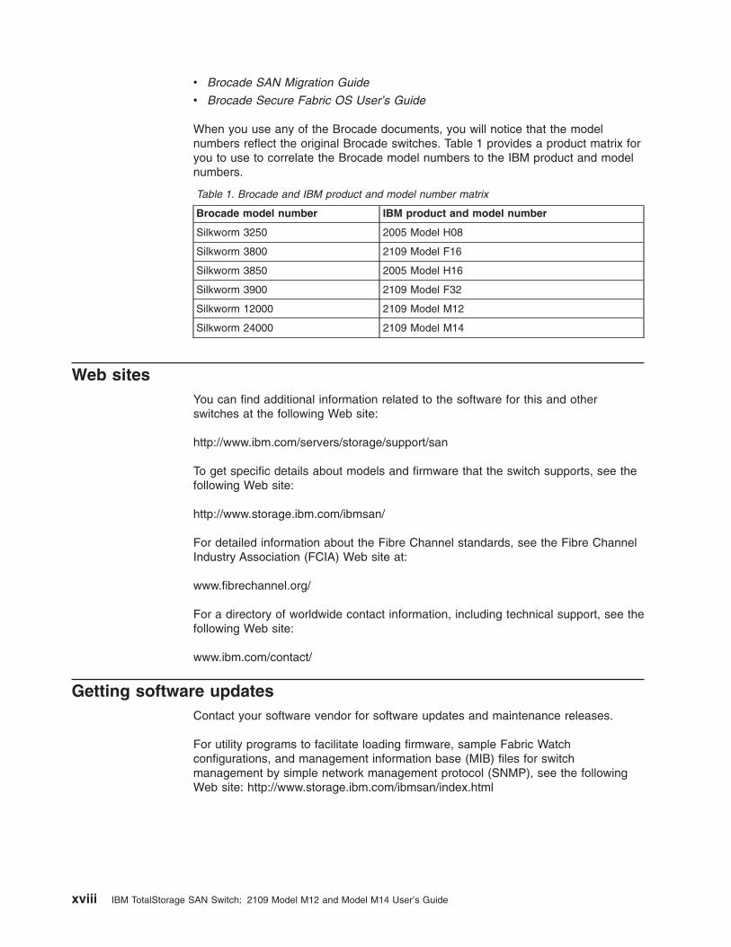
When
you
use
any
of
the
Brocade
documents,
you
will
notice
that
the
model
numbers
reflect
the
original
Brocade
switches.
Table
1
provides
a
product
matrix
for
you
to
use
to
correlate
the
Brocade
model
numbers
to
the
IBM
product
and
model
numbers.
Table
1.
Brocade
and
IBM
product
and
model
number
matrix
Brocade
model
number
IBM
product
and
model
number
Silkworm
3250
2005
Model
H08
Silkworm
3800
2109
Model
F16
Silkworm
3850
2005
Model
H16
Silkworm
3900
2109
Model
F32
Silkworm
12000
2109
Model
M12
Silkworm
24000
2109
Model
M14
Web
sites
You
can
find
additional
information
related
to
the
software
for
this
and
other
switches
at
the
following
Web
site:
http://www.ibm.com/servers/storage/support/san
To
get
specific
details
about
models
and
firmware
that
the
switch
supports,
see
the
following
Web
site:
http://www.storage.ibm.com/ibmsan/
For
detailed
information
about
the
Fibre
Channel
standards,
see
the
Fibre
Channel
Industry
Association
(FCIA)
Web
site
at:
www.fibrechannel.org/
For
a
directory
of
worldwide
contact
information,
including
technical
support,
see
the
following
Web
site:
www.ibm.com/contact/
Getting
software
updates
Contact
your
software
vendor
for
software
updates
and
maintenance
releases.
For
utility
programs
to
facilitate
loading
firmware,
sample
Fabric
Watch
configurations,
and
management
information
base
(MIB)
files
for
switch
management
by
simple
network
management
protocol
(SNMP),
see
the
following
Web
site:
http://www.storage.ibm.com/ibmsan/index.html
xviii
IBM
TotalStorage
SAN
Switch:
2109
Model
M12
and
Model
M14
User’s
Guide

Getting
help
Contact
your
switch
supplier
for
technical
support.
This
includes
hardware
support,
all
product
repairs,
and
ordering
of
spare
components.
Be
prepared
to
provide
the
following
information
to
support
personnel:
v
The
switch
serial
number
v
The
switch
worldwide
name
(licenseidshow
command)
v
The
configuration
(topologyshow
command)
v
Any
output
from
the
supportShow
Telnet
command
v
A
detailed
description
of
the
problem
v
Any
troubleshooting
steps
that
you
have
already
performed
How
to
send
your
comments
Your
feedback
is
important
in
helping
us
provide
the
most
accurate
and
high-quality
information.
If
you
have
comments
or
suggestions
for
improving
this
document,
you
can
send
us
comments
electronically
by
using
the
following
addresses:
v
Internet:
v
IBMLink™
from
U.S.A.:
STARPUBS
at
SJEVM5
v
IBMLink
from
Canada:
STARPUBS
at
TORIBM
v
IBM
Exchange:
USIB3VVD
at
IBMMAIL
You
can
also
your
comments
by
using
the
Reader
Comment
Form
in
the
back
of
this
manual
or
direct
your
to:
International
Business
Machines
Corporation
Information
Development
Department
GZW
9000
South
Rita
Road
Tucson,
Arizona
85744–0001
U.S.A.
When
you
send
information
to
IBM,
you
grant
IBM
a
nonexclusive
right
to
use
or
distribute
the
information
in
any
way
it
believes
appropriate
without
incurring
any
obligation
to
you.
About
this
document
xix

xx
IBM
TotalStorage
SAN
Switch:
2109
Model
M12
and
Model
M14
User’s
Guide
Chapter
1.
Introduction
This
chapter
provides
an
overview
of
the
IBM
TotalStorage
SAN
Switch
2109
Model
M12
and
the
Model
M14.
For
the
remainder
of
this
document,
these
switches
will
be
referred
to
as
the
Model
M12
and
Model
M14,
or
simply
the
M12
and
M14.
These
two
switches
will
also
be
referred
to
as
switches,
when
appropriate.
Information
that
is
common
for
both
the
M12
and
M14
switches
will
be
presented
together,
and
information
that
applies
to
only
one
of
the
switches
will
be
identified
specifically.
Product
overview
The
2109
Model
M12
and
M14
switches
are
advanced
fibre-channel
switches
that
are
used
to
intelligently
interconnect
storage
devices,
hosts,
and
servers
in
a
storage
area
network
(SAN).
They
are
revolutionary
fibre-channel
switch
products,
providing
up
to
128–ports
that
deliver
unprecedented
performance,
scalability,
flexibility,
functionality,
reliability,
and
availability.
See
Figure
1
on
page
3
and
Figure
2
on
page
4.
v
The
M12
and
M14
both
deliver
a
very
high-density
port,
rack-ready
solution
to
drive
cost-effective
SAN.
v
The
dual
switch
capability
allows
either
one
or
two
64–port
switches
per
chassis.
The
switches
can
be
interconnected
to
create
a
high
port
count
solution,
or
they
can
be
used
in
a
dual
fabric,
high
availability
topology.
v
The
switches
support
1
Gbps
and
2
Gbps
auto-sensing
fibre-channel
ports.
Trunking
technology
groups
up
to
four
ports
together
to
create
high
performance
8
Gbps
ISL
trunks
between
switches.
v
Universal
ports
self-configure
as
E_ports,
F_ports,
or
FL_ports.
v
Small
form-factor
pluggable
(SFP)
optical
transceivers
support
any
combination
of
short
wavelength
(SWL)
and
long
wavelength
(LWL)
optical
media
on
a
single
switch
module.
v
The
switches
offer
a
high
availability
platform
for
mission-critical
SAN-designed
applications.
v
Dual
redundant
CPs
provide
high
availability
and
enable
nondisruptive
software
upgrades.
v
Both
switches
offer
forward
and
backward
compatibility
with
all
IBM
SAN
switches.
v
The
Fabric
operating
system
(OS)
delivers
distributed
intelligence
throughout
the
network
and
enables
a
wide
range
of
value-added
applications
including
Extended
Fabrics,
Fabric
Access,
Fabric
Watch,
Remote
Switch,
Web
Tools,
and
Advanced
Zoning.
v
High
availability
redundant
design,
extensive
diagnostics,
and
system
monitoring
capabilities
integrated
with
Fabric
OS
management
tools
deliver
unprecedented
reliability,
availability,
and
serviceability.
The
switches
are
nonblocking
core
fabric
switches.
They
never
prevent
a
server
from
being
able
to
connect
to
storage,
even
under
congestion.
The
backplane
bandwidth
between
ports
on
the
switches
is
sufficient
to
allow
traffic
to
flow
at
full
bandwidth.
©
Copyright
IBM
Corp.
2004
1
Throughput
The
M12
and
M14
provide
continuous
and
sustained
bandwidth
to
all
ports
in
a
single
or
dual
32-port
or
64-port
switch
scenario
at
their
rated
line
speed.
Throughput
is
2.125
Gbps
inbound
and
outbound
per
port.
All
ports
can
be
simultaneously
loaded
for
up
to
100%
utilization
at
full
bandwidth.
The
M14
backplane
provides
support
for
a
128-port
switch,
10
bps
fibre
channel,
IP
connectivity,
application
processing
and
Infiniband.
Each
port
on
the
switch
is
auto-sensing
and
supports
1
Gbps
or
2
Gbps
speeds.
You
can
manually
set
the
ports
to
support
either
1
Gbps
or
2
Gbps
links.
The
ports
perform
speed-matching,
which
allows
1
Gbps
and
2
Gbps
links
to
mix
on
any
route
within
the
fabric.
When
there
is
1
Gbps
in
and
2
Gbps
out,
the
ASIC
delays
transmitting
the
outbound
frame
until
half
the
frame
is
received
at
1
Gbps.
With
2
Gbps
in
and
1
Gbps
out,
the
ASIC
delays
releasing
the
buffer
to
ensure
that
the
1
Gbps
transmit
port
has
adequate
time
to
empty
it.
Link
distance
The
M12
and
M14
operate
at
up
to
10
km
(6.21
mi)
at
both
1
Gbps
and
2
Gbps
speed
settings
and
supports
LWL
SFPs
and
single-mode
fiber.
Using
the
Extended
Fabrics
optional
software
feature,
the
switch
operates
at
distances
greater
than
10
km
(6.21
mi)
using
various
methods.
The
switch
leverages
the
current
dense
wavelength
division
multiplexing
(DWDM)
certification
and
is
certified
to
interoperate
with
equipment
from
Optical
Networks,
Cisco
Systems,
Inc.,
Nortel
Networks,
and
other
leading
vendors.
The
switch
operates
at
near
full
link
speed
at
distances
up
to
100
km
(62.13
mi)
for
1
Gbps
or
50
km
(31.06
mi)
for
2
Gbps
speeds
using
the
Extended
Fabrics
feature.
For
information
about
Extended
Fabrics,
see
Brocade
Design,
Deployment,
and
Management
Guide.
SFP
fiber
optic
transceivers
Each
16–port
card
(blade
assembly)
supports
up
to
16
SFP
fiber
optic
transceivers
that
convert
electrical
signals
to
optical
signals
(and
optical
signals
to
electrical
signals)
and
are
capable
of
transmitting
at
both
1
Gbps
and
2
Gbps
speeds.
Each
SFP
fiber
optic
transceiver
supports
850
nm
SWL,
on
multimode
fiber
optic
cable,
or
1310
nm
LWL,
on
single
mode
fiber
optic
cable.
These
miniature
optical
transceivers
meet
the
high
port
density
that
is
available
in
the
M12
and
M14
switches,
deliver
twice
the
port
density
of
standard
removable
GBIC
transceivers,
and
are
encased
in
metal
or
shielded
plastic
to
ensure
low
emissions
and
high
thermal
management.
SFP
devices
are
hot-swappable
and
connections
are
through
industry-standard
LC
connectors.
2
IBM
TotalStorage
SAN
Switch:
2109
Model
M12
and
Model
M14
User’s
Guide
Chapter
2.
System
design
overview
The
M12
and
M14
switches
are
designed
with
a
number
of
features
that
ensure
that
these
switches
are
highly
available,
reliable,
and
serviceable.
These
products
have
a
number
of
modular
design
features,
allowing
for
ease
and
speed
of
maintenance,
as
well
as
future
expansion.
Some
of
the
basic
features
are
shown
in
Figure
1
and
Figure
2
on
page
4,
and
are
described
in
sections
below.
RS
-232
RS
-232
Link
10/100 Mb/s
Link
10/100 Mb/s
! ! ! ! ! ! ! ! ! !
Slot
1 2 3 4 5 6 7 8 9 10Exhaust Vent
PowerSupply 4
PowerSupply 3
PowerSupply 2
PowerSupply 1
AC PowerSwitch
AC PowerSwitch
AC PowerConnector
AC PowerConnector
GroundingStrap
Connector
CP Card
16-Port Card
(Provide Power to Power Supply 1 and 3) (Provide Power to Power Supply 2 and 4) SJ000634
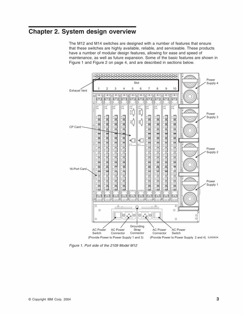
Figure
1.
Port
side
of
the
2109
Model
M12
©
Copyright
IBM
Corp.
2004
3
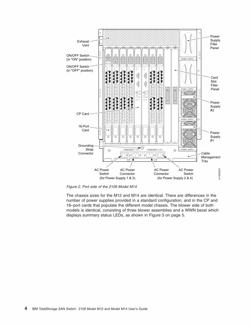
The
chassis
sizes
for
the
M12
and
M14
are
identical.
There
are
differences
in
the
number
of
power
supplies
provided
in
a
standard
configuration,
and
in
the
CP
and
16–port
cards
that
populate
the
different
model
chassis.
The
blower
side
of
both
models
is
identical,
consisting
of
three
blower
assemblies
and
a
WWN
bezel
which
displays
summary
status
LEDs,
as
shown
in
Figure
3
on
page
5.
scal e:3/ 16" = 1"
POWER SUPPLY 2
POWER SUPPLY 3
POWER SUPPLY 4
POWER SUPPLY 1
1 2 3 4 5 6 7 8 9 10
200-240 VAC 12A 50-60 Hz 200-240 VAC 12A 50-60 Hz
!
!
!
!
POWER SUPPLY 1 & 3 POWER SUPPLY 2 & 4
CP Card
Exhaust
Vent
ON/OFF Switch
(in "ON" position)
ON/OFF Switch
(in "OFF" position)
16-Port
Card
AC Power
Switch
AC Power
Connector
(for Power Supply 1 & 3) (for Power Supply 2 & 4)
AC Power
Switch
AC Power
Connector
Grounding
Strap
Connector
Power
Supply
Filler
Panel
Card
Slot
Filler
Panel
Power
Supply
#2
Power
Supply
#1
Cable
Management
Tray
Link
10/100 Mb/s
!
Active CP
IOIO
IRS
-232
Link
10/100 Mb/s
!
Active CP
IOIO
IRS
-232
!
15
d
14
c
13
b
12
a
11
d
10
c
9
b
8
a
7
d
6
c
5
b
4
a
3
d
2
c
1
b
0
a
!
15
d
14
c
13
b
12
a
11
d
10
c
9
b
8
a
7
d
6
c
5
b
4
a
3
d
2
c
1
b
0
a
!
15
d
14
c
13
b
12
a
11
d
10
c
9
b
8
a
7
d
6
c
5
b
4
a
3
d
2
c
1
b
0
a
!
15
d
14
c
13
b
12
a
11
d
10
c
9
b
8
a
7
d
6
c
5
b
4
a
3
d
2
c
1
b
0
a
!
15
d
14
c
13
b
12
a
11
d
10
c
9
b
8
a
7
d
6
c
5
b
4
a
3
d
2
c
1
b
0
a
!
15
d
14
c
13
b
12
a
11
d
10
c
9
b
8
a
7
d
6
c
5
b
4
a
3
d
2
c
1
b
0
a
m1400001
Figure
2.
Port
side
of
the
2109
Model
M14
4
IBM
TotalStorage
SAN
Switch:
2109
Model
M12
and
Model
M14
User’s
Guide
These
benefits
of
these
features
are
described
in
more
detail
in
the
following
sections.
High
Availability
The
switch
high
availability
features
include:
v
Redundant,
hot-swappable
control
processors
(CPs)
with
automatic
failover
v
Dual
redundant
ac
input
v
Hot-swappable,
redundant
power
supplies
in
the
power
subsystem
v
Hot-swappable
blowers
in
the
redundant
cooling
system
v
Hot-swappable
16–port
switch
modules
v
Non-disruptive
″hot″
firmware/software
code
loads
and
activation
v
Easy
configuration,
save,
and
restore
v
Enhanced
data
integrity
on
all
data
paths
�����������������������������������������������������������������������������������������������������������������������������������������������������������������������������������������������������������������������������������������������������������������������������������������������������������������������������������������������������������������������������������������������������������������������������������������������������������������������������������������������������������������������������������������������������������������������������������������������������������������������������������������������������������������������������������������������������������������������������������������������������������������������������������������������������������������������������������������������������������������������������������������������������������������������������������������������������������������������������������������������������������������������������������������������������������������������������������������������������������������������������������������������������������������������������������������������������������������������������������������������������������������������������������������������������������������������������������������������������������������������������������������������������
�������������������������������������������������������������������������������������������������������������������������������������������������������������������������������������������������������������������������������������������������������������������������������������������������������������������������������������������������������
����������������������������������������������������������������������������������������������������������������������������������������������������������������������������������������������������������������������������������������������������������������������������������������������������������������������������������������������������
������������������������������������������������������������������������������������������������������������������������������������������������������������������������������������������������������������������������������������������������������������������������������������������������������������������������������������������������������������������������������������������������������������������������������������������������������������������������������������������������������������������������������������������������������������������������������������������������������������������������������������������������������������������������������������������������������������������������������������������������������������������������������������������������������������������������������������������������������������������������������������������������������������������������������������������������������������������������������������������������������������������������������������������������������������������������������������������������������������������������������������������������������������������������������������������������������������������������������������������������������������������������������������������������������������������������������������������������������������������������������������������������������������������������������������������������������������������������������������������������������������������������������������������������������������������������������������������������������������������������������������������������������������������������������������������������������������������������������������������������������������������������������������������������������������������������������������������������������������������������������������������������������������������������������������������������������������������������������������������������������������������������������������������������������������������������������������������������������������������������������������������������������������������������������������������������������������������������������������������������������������������������������������������������������������������������������������������������������������������������������������������������������������������������������������������������������������������������������������������������������������������������������������������������������������������������������������������������������������������������������������������������������������������������������������������������������������������������������������������������������������������������������������������������������������������������������������������������������������������
����������������������������������������������������������������������������������������������������������������������������������������������������������������������������������������������������������������������������������������������������������������������������������������������������������������������������������������������������������������������������������������������������������������������������������������������������������������������������������������������������������������������������������������������������������������������������������������������������������������������������������������������������������������������������������������������������������������������������������������������������������������������
101 2 3 4 5 6 7 8 9
Port Card andCP Card LEDs WWN Bezel Power Supply LEDs
BlowerPowerLED
BlowerFaultLED
BlowerHandle
Blower Assembly 3
Blower Assembly 2
Blower Assembly 1
pwr1
pwr2
pwr3
pwr4
SJ000635
Figure
3.
Blower
(non-port)
side
of
the
M12
and
M14
Chapter
2.
System
design
overview
5
v
Fabric
Shortest
Path
First
(FSPF)
rerouting
around
failed
links
v
Integration
with
SNMP
managers
The
high-availability
software
architecture
of
these
switches
provides
a
common
framework
for
all
applications
that
reside
on
the
system,
allowing
global
and
local
states
to
be
maintained
enough
to
manage
any
component
failure.
High-availability
elements
consist
of
the
High
Availability
Manager,
the
heartbeat,
the
fault/health
framework,
the
replicated
database,
initialization,
and
software
upgrade.
The
High
Availability
manager:
v
Controls
access
to
the
standby
CP
v
Facilitates
software
upgrades
v
Prevents
extraneous
switch-over
activity
v
Closes
and
flushes
streams
as
needed
v
Provides
flow
control
and
message
buffering
v
Supports
a
centralized
active
and
standby
state
allowing
the
switch
of
activity
to
be
controlled
from
a
single
point.
Reliability
In
addition
to
being
available,
the
system
must
be
reliable.
This
means
that
some,
if
not
all,
of
its
state
must
be
maintained.
In
a
reliable
system,
you
are
not
aware
of
the
internal
state
of
a
switch,
and
you
experience
continued
system
service
with
zero
degradation.
The
M12
and
M14
switches
provide
the
following
features
to
ensure
reliability:
v
Power-on
self
test
(POST).
v
An
error
detection
and
correction
mechanism
to
protect
all
data
in
the
switch.
v
Error
detection
and
fault
isolation,
such
as
cyclic
redundancy
checking
(CRC),
parity
checking,
checksum,
and
illegal
address
checking.
v
Dual
CPs
that
enable
hot,
nondisruptive
fast
firmware
upgrades.
Each
CP
contains
two
serial
ports
and
one
Ethernet
port.
Offline
CP
diagnostics
and
remote
diagnostics
make
troubleshooting
easy.
The
standby
CP
continuously
runs
diagnostics
to
ensure
that
it
is
operational
should
a
failover
be
necessary.
v
Inter-IC
(I²C)
monitoring
and
control.
Serviceability
The
M12
and
M14
provide
the
following
features
to
enhance
and
ensure
serviceability:
v
Modular
design
with
hot-swappable
components
v
Redundant
flash
memory
that
stores
two
firmware
images
per
CP
v
Extensive
diagnostics
and
status
reporting,
along
with
a
serial
port
to
support
an
external,
country-specific
modem
for
remote
diagnostics
and
status
monitoring
v
Nonvolatile
random-access
memory
(NVRAM)
that
contains
the
OEM
serial
number,
IBM
serial
number,
revision
information,
and
part
number
information
v
Background
health
check
daemon
v
Memory
scrubber,
self
test,
and
bus
ping
to
determine
if
a
bus
is
not
functioning
v
Watchdog
timers
v
Status
LEDs
v
Predictive
diagnostics
analysis
through
Fabric
Watch
6
IBM
TotalStorage
SAN
Switch:
2109
Model
M12
and
Model
M14
User’s
Guide
v
SNMP
integration
with
higher
layer
managers
For
basic
information
about
diagnostics,
see
Chapter
5,
“Fault
monitoring
and
diagnostics,”
on
page
19.
Refer
to
Brocade
Diagnostic
and
System
Error
Message
Reference
for
more
detailed
information.
For
information
about
Fabric
Watch,
see
Brocade
Fabric
Watch
User’s
Guide.
Hot-swappable
FRUs
Many
of
the
modular
hot-swappable
field
replaceable
units
(FRUs)
can
be
replaced
in
less
than
ten
minutes
by
a
qualified
service
representative.
The
hot-swappable
FRUs
for
both
the
M12
and
M14
include
the
following:
v
16–port
switch
blade
assembly
v
CP
blade
assembly
v
SFP
optical
transceivers
v
Blower
assembly
v
Power
supply
v
A
cable
management
tray
and
cable
guides
(pillars).
v
A
worldwide
name
(WWN)
light-emitting
diode
(LED)
card
on
the
non-port
side
that
maintains
chassis-specific
information,
such
as
WWNs,
Internet
Protocol
(IP)
addresses
and
summary
status
information
of
each
blade
assembly
and
power
supply.
Up
to
eight
hot-swappable
16-port
switch
blade
assemblies
can
be
installed
to
deliver
up
to
two
separate
64-port
fibre-channel
switches
in
a
single
chassis
(or
a
128–port
fibre-channel
switch,
M14
only).
Two
CP
blade
assemblies
are
installed
in
each
chassis
to
provide
automatic
failover
protection.
A
single
active
CP
can
control
both
logical
switches
in
the
chassis,
allowing
the
replacement
of
the
other
CP
without
disruption.
Cables,
blade
assemblies,
and
power
supplies
are
serviced
from
the
cable
side
of
the
switch,
and
blowers
are
serviced
from
the
noncable
side.
Ports
Each
switch
blade
assembly
houses
16
auto-sensing
1–Gbps
or
2–Gbps
fibre-channel
ports
and
uses
SFP
optical
transceivers.
The
M12
and
M14
switches
support
the
following
port
types:
v
Optical
ports
v
Ethernet
port
v
Serial
port
Optical
ports
Fibre-channel
interfaces
of
the
M12
and
M14
are
equipped
with
an
optical
port
interface
that
uses
an
SWL,
780
to
850
nm,
or
an
LWL,
1270
to
1350
nm,
laser
transmitter.
The
laser
complies
with
FDA21
CFR
(J)
Class
1
laser
safety
requirements.
It
uses
non-Open
Fibre
Control
(OFC)
optical
SFPs
in
the
M12
or
M14
series
circuit.
Safe
Class
1
operation
is
guaranteed
by
limiting
the
optical
power
that
is
emitted
by
the
port,
which
eliminates
the
need
for
physical
shutters.
The
optical
SFP
uses
the
LC-duplex
connector
scheme.
Chapter
2.
System
design
overview
7
Ethernet
port
The
M12
and
M14
provide
a
fully
IEEE
compliant
10BASE-T
or
100BASE-T
Ethernet
port
for
switch
management.
The
port
has
two
LEDs
that
indicates:
v
Speed
(10
Mbps
or
100
Mbps)
v
Status
of
the
connection
Additionally,
each
CP
has
its
own
Ethernet
port.
You
can
choose
to
connect
the
Ethernet
ports
to
each
other
through
an
Ethernet
switch
or
to
connect
them
to
separate
networks
for
greater
availability.
Each
CP
has
its
own
unique
IP
address
and
is
accessible
independent
of
the
other
CP.
Serial
port
Each
CP
comes
with
two
serial
ports.
The
top
serial
port
on
the
installed
CP
is
an
RS–232
port
that
is
used
for
remote
dial-in.
The
bottom
port
is
used
for
accessing
the
console.
Numbering
The
M12
and
M14
switches
use
a
numbering
scheme
that
progresses
from
left
to
right
and
bottom
to
top
in
numerical
order.
The
reference
location
is
from
the
cable
side
of
the
chassis.
v
Blade
assemblies
are
numbered
from
1—10,
from
left
to
right.
v
Ports
are
numbered
from
0—15,
from
bottom
to
top.
v
Power
supplies
are
numbered
from
1—4,
from
bottom
to
top.
v
Blowers
are
numbered
from
1—3,
from
left
to
right.
Rack
mounting
The
mechanical
design
of
the
M12
and
M14
allows
rack
mounting
with
either
the
cable
side
or
the
noncable
side
facing
the
front
of
the
equipment
rack.
The
chassis
fits
into
a
standard
19-inch
EIA
rack.
Each
chassis
measures:
v
43.74
cm
(17.22
in.)
wide
v
70.87
cm
(27.9
in.)
deep
(without
the
door)
v
61.24
cm
(24.11
in.)
high
(less
than
14U)
Cooling
system
The
M12
and
M14
use
a
redundant
system
of
three
hot-swappable
blowers.
Cool
air
intake
is
from
the
noncable
side
of
the
chassis,
is
pressurized,
and
is
forced
through
the
system.
Heated
air
exits
at
the
top
of
the
cable
side
of
the
chassis.
The
unit
is
cooled
by
three
blowers
that
are
used
in
conjunction
with
a
pressurized
plenum.
Each
blower
assembly
includes
a
blower
control
assembly,
which
provides
the
following
features:
v
Blower
status
LEDs
v
Blower
speed
sensing
v
Blower
speed
control
v
Serial
electronically
erasable
programmable
read
only
memory
(EEPROM)
that
contains
the
part
number,
revision
level,
and
error
logs
for
the
blade
assembly
v
Inlet
air
temperature
monitoring
8
IBM
TotalStorage
SAN
Switch:
2109
Model
M12
and
Model
M14
User’s
Guide
The
M12
and
M14
switches
operate
indefinitely
if
a
single
blower
fails.
When
a
blower
assembly
is
removed,
a
mechanical
flap
seals
the
air
chamber
to
maintain
positive
cooling
air
pressure
in
the
chassis
while
the
failed
blower
assembly
is
being
replaced.
Cable
management
The
cable
management
tray
and
cable
pillars
provide
easy
access
to
the
switch
cables
and
allow
you
to
organize
and
maintain
the
cables
easily.
Up
to
128
pairs
of
fibre
optic
cables
can
be
maintained
on
a
single
chassis.
The
cable
management
system
is
designed
to
allow
any
switch
module
to
be
replaced
without
disrupting
service
on
any
adjacent
blade
assemblies.
Worldwide
name
LED
card
The
worldwide
name
(WWN)
LED
card
is
the
neutral
location
to
accommodate
the
worldwide
unique
serial
ID
for
each
logical
switch
on
the
M12
and
M14.
It
is
an
integral
part
of
the
chassis.
The
serial
EEPROM
device
contains
multiple
serial
numbers
for
identifying
the
chassis,
back
plane,
and
the
WWN
card
itself.
As
an
alternative
system
status
indicator,
this
card
consolidates
the
status
of
all
modular
components
in
the
system
on
the
cable
side
and
presents
the
status
to
you
in
the
form
of
LEDs
on
the
noncable
side.
The
arrangement
of
the
LEDs
on
this
card
resembles
the
look
of
status
LEDs
on
the
other
side
of
the
switch.
The
LEDs
provide
the
summary
of
cable-side
system
status
on
the
switch
as
follows:
v
Two
LEDs
per
blade
assembly
on
the
cable
side
of
the
cabinet.
–
Green
indicates
that
the
power
is
OK.
–
Amber
indicates
that
the
blade
needs
attention.
v
Two
LEDs
per
power
supply.
Both
LEDs
are
in
the
same
location.
–
Green
indicates
that
the
power
is
OK.
–
Amber
indicates
that
the
power
supply
needs
attention.
A
worldwide
name
(WWN)
light-emitting
diode
(LED)
card
on
the
non-port
side
that
maintains
chassis-specific
information,
such
as
WWNs,
Internet
Protocol
(IP)
addresses
and
summary
status
information
of
each
blade
assembly
and
power
supply.
Chapter
2.
System
design
overview
9

10
IBM
TotalStorage
SAN
Switch:
2109
Model
M12
and
Model
M14
User’s
Guide
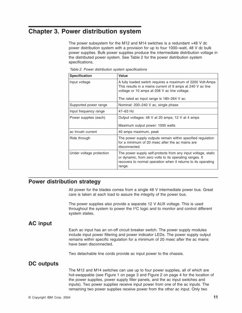
Chapter
3.
Power
distribution
system
The
power
subsystem
for
the
M12
and
M14
switches
is
a
redundant
+48
V
dc
power
distribution
system
with
a
provision
for
up
to
four
1000–watt,
48
V
dc
bulk
power
supplies.
Bulk
power
supplies
produce
the
intermediate
distribution
voltage
in
the
distributed
power
system.
See
Table
2
for
the
power
distribution
system
specifications.
Table
2.
Power
distribution
system
specifications
Specification
Value
Input
voltage
A
fully
loaded
switch
requires
a
maximum
of
2200
Volt-Amps.
This
results
in
a
mains
current
of
9
amps
at
240
V
ac
line
voltage
or
10
amps
at
208
V
ac
line
voltage.
The
rated
ac
input
range
is
180–264
V
ac.
Supported
power
range
Nominal:
200–240
V
ac,
single
phase
Input
frequency
range
47–63
Hz
Power
supplies
(each)
Output
voltages:
48
V
at
20
amps;
12
V
at
4
amps
Maximum
output
power:
1000
watts
ac
Inrush
current
40
amps
maximum,
peak
Ride
through
The
power
supply
outputs
remain
within
specified
regulation
for
a
minimum
of
20
msec
after
the
ac
mains
are
disconnected.
Under
voltage
protection
The
power
supply
self-protects
from
any
input
voltage,
static
or
dynamic,
from
zero
volts
to
its
operating
ranges.
It
recovers
to
normal
operation
when
it
returns
to
its
operating
range.
Power
distribution
strategy
All
power
for
the
blades
comes
from
a
single
48
V
intermediate
power
bus.
Great
care
is
taken
at
each
load
to
assure
the
integrity
of
the
power
bus.
The
power
supplies
also
provide
a
separate
12
V
AUX
voltage.
This
is
used
throughout
the
system
to
power
the
I²C
logic
and
to
monitor
and
control
different
system
states.
AC
input
Each
ac
input
has
an
on-off
circuit
breaker
switch.
The
power
supply
modules
include
input
power
filtering
and
power
indicator
LEDs.
The
power
supply
output
remains
within
specific
regulation
for
a
minimum
of
20
msec
after
the
ac
mains
have
been
disconnected.
Two
detachable
line
cords
provide
ac
input
power
to
the
chassis.
DC
outputs
The
M12
and
M14
switches
can
use
up
to
four
power
supplies,
all
of
which
are
hot-swappable
(see
Figure
1
on
page
3
and
Figure
2
on
page
4
for
the
location
of
the
power
supplies,
power
supply
filler
panels,
and
the
ac
input
switches
and
inputs).
Two
power
supplies
receive
input
power
from
one
of
the
ac
inputs.
The
remaining
two
power
supplies
receive
power
from
the
other
ac
input.
Only
two
©
Copyright
IBM
Corp.
2004
11
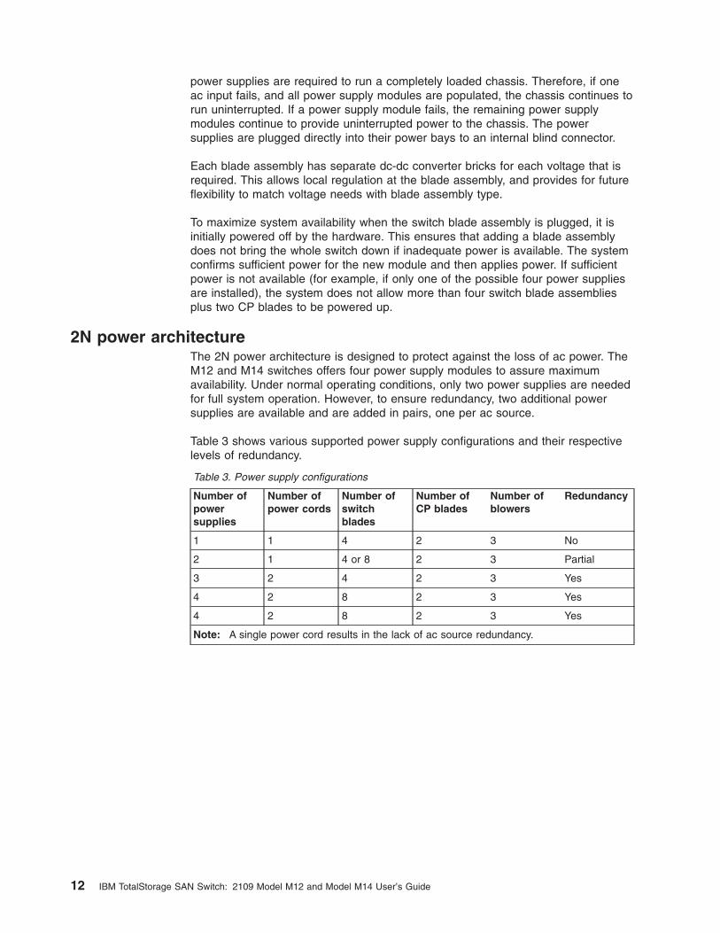
power
supplies
are
required
to
run
a
completely
loaded
chassis.
Therefore,
if
one
ac
input
fails,
and
all
power
supply
modules
are
populated,
the
chassis
continues
to
run
uninterrupted.
If
a
power
supply
module
fails,
the
remaining
power
supply
modules
continue
to
provide
uninterrupted
power
to
the
chassis.
The
power
supplies
are
plugged
directly
into
their
power
bays
to
an
internal
blind
connector.
Each
blade
assembly
has
separate
dc-dc
converter
bricks
for
each
voltage
that
is
required.
This
allows
local
regulation
at
the
blade
assembly,
and
provides
for
future
flexibility
to
match
voltage
needs
with
blade
assembly
type.
To
maximize
system
availability
when
the
switch
blade
assembly
is
plugged,
it
is
initially
powered
off
by
the
hardware.
This
ensures
that
adding
a
blade
assembly
does
not
bring
the
whole
switch
down
if
inadequate
power
is
available.
The
system
confirms
sufficient
power
for
the
new
module
and
then
applies
power.
If
sufficient
power
is
not
available
(for
example,
if
only
one
of
the
possible
four
power
supplies
are
installed),
the
system
does
not
allow
more
than
four
switch
blade
assemblies
plus
two
CP
blades
to
be
powered
up.
2N
power
architecture
The
2N
power
architecture
is
designed
to
protect
against
the
loss
of
ac
power.
The
M12
and
M14
switches
offers
four
power
supply
modules
to
assure
maximum
availability.
Under
normal
operating
conditions,
only
two
power
supplies
are
needed
for
full
system
operation.
However,
to
ensure
redundancy,
two
additional
power
supplies
are
available
and
are
added
in
pairs,
one
per
ac
source.
Table
3
shows
various
supported
power
supply
configurations
and
their
respective
levels
of
redundancy.
Table
3.
Power
supply
configurations
Number
of
power
supplies
Number
of
power
cords
Number
of
switch
blades
Number
of
CP
blades
Number
of
blowers
Redundancy
1
1
4
2
3
No
2
1
4
or
8
2
3
Partial
3
2
4
2
3
Yes
4
2
8
2
3
Yes
4
2
8
2
3
Yes
Note:
A
single
power
cord
results
in
the
lack
of
ac
source
redundancy.
12
IBM
TotalStorage
SAN
Switch:
2109
Model
M12
and
Model
M14
User’s
Guide
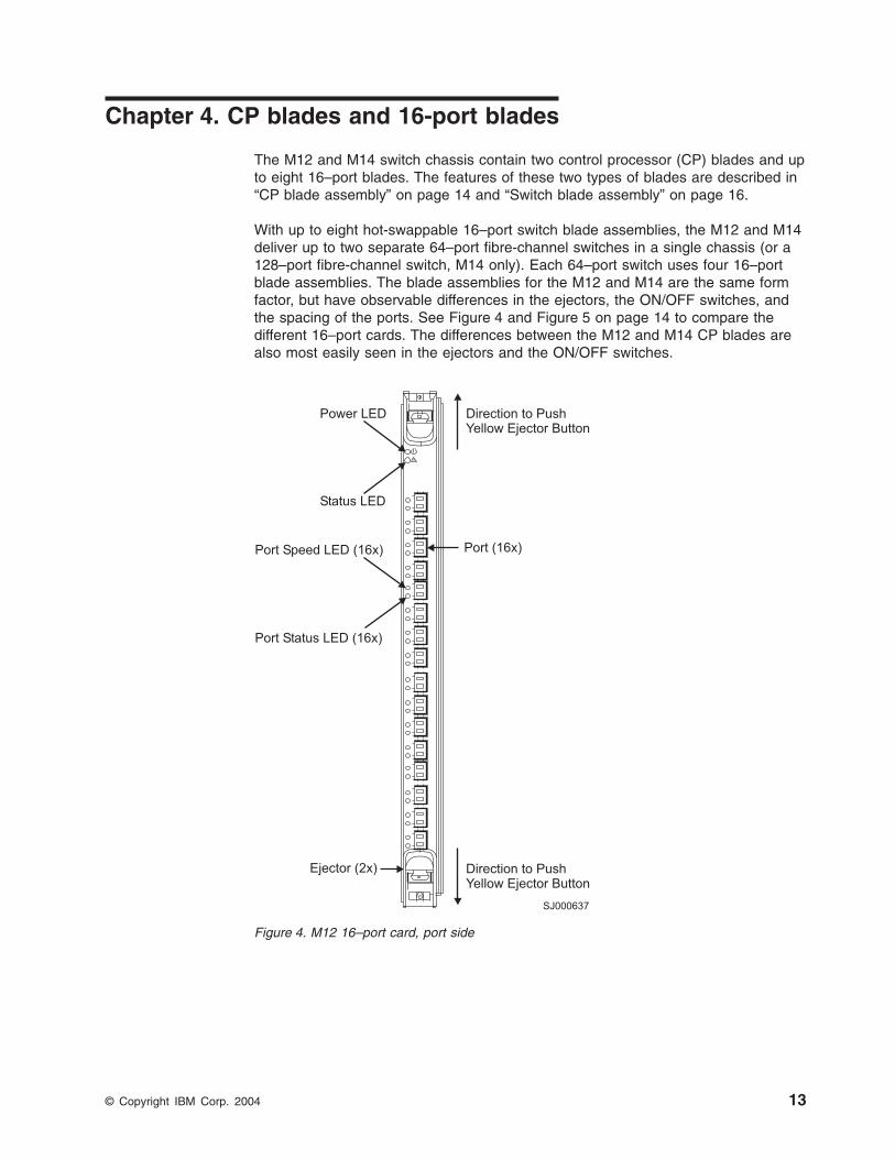
Chapter
4.
CP
blades
and
16-port
blades
The
M12
and
M14
switch
chassis
contain
two
control
processor
(CP)
blades
and
up
to
eight
16–port
blades.
The
features
of
these
two
types
of
blades
are
described
in
“CP
blade
assembly”
on
page
14
and
“Switch
blade
assembly”
on
page
16.
With
up
to
eight
hot-swappable
16–port
switch
blade
assemblies,
the
M12
and
M14
deliver
up
to
two
separate
64–port
fibre-channel
switches
in
a
single
chassis
(or
a
128–port
fibre-channel
switch,
M14
only).
Each
64–port
switch
uses
four
16–port
blade
assemblies.
The
blade
assemblies
for
the
M12
and
M14
are
the
same
form
factor,
but
have
observable
differences
in
the
ejectors,
the
ON/OFF
switches,
and
the
spacing
of
the
ports.
See
Figure
4
and
Figure
5
on
page
14
to
compare
the
different
16–port
cards.
The
differences
between
the
M12
and
M14
CP
blades
are
also
most
easily
seen
in
the
ejectors
and
the
ON/OFF
switches.
!
Port Status LED (16x)
Port Speed LED (16x)
Power LED Direction to PushYellow Ejector Button
Direction to PushYellow Ejector Button
Status LED
Ejector (2x)
Port (16x)
SJ000637
Figure
4.
M12
16–port
card,
port
side
©
Copyright
IBM
Corp.
2004
13
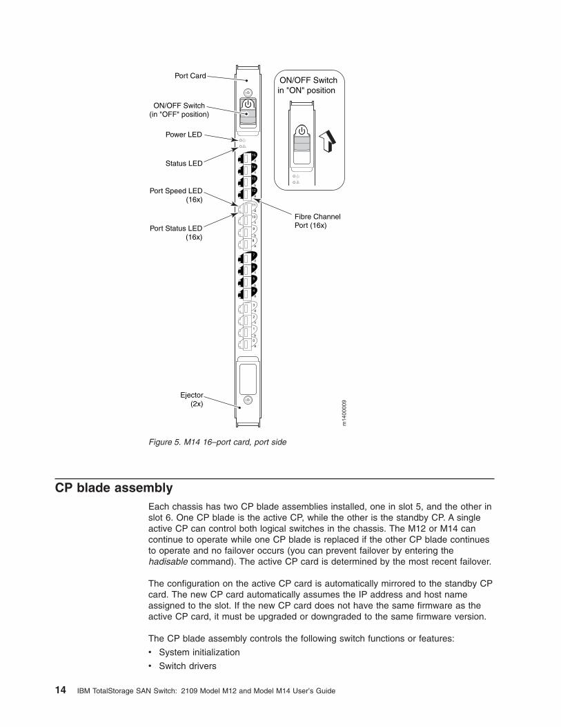
CP
blade
assembly
Each
chassis
has
two
CP
blade
assemblies
installed,
one
in
slot
5,
and
the
other
in
slot
6.
One
CP
blade
is
the
active
CP,
while
the
other
is
the
standby
CP.
A
single
active
CP
can
control
both
logical
switches
in
the
chassis.
The
M12
or
M14
can
continue
to
operate
while
one
CP
blade
is
replaced
if
the
other
CP
blade
continues
to
operate
and
no
failover
occurs
(you
can
prevent
failover
by
entering
the
hadisable
command).
The
active
CP
card
is
determined
by
the
most
recent
failover.
The
configuration
on
the
active
CP
card
is
automatically
mirrored
to
the
standby
CP
card.
The
new
CP
card
automatically
assumes
the
IP
address
and
host
name
assigned
to
the
slot.
If
the
new
CP
card
does
not
have
the
same
firmware
as
the
active
CP
card,
it
must
be
upgraded
or
downgraded
to
the
same
firmware
version.
The
CP
blade
assembly
controls
the
following
switch
functions
or
features:
v
System
initialization
v
Switch
drivers
scale: 5/16" = 1"
Power LED
Status LED
Fibre ChannelPort (16x)
Port Card
!
15
d
14
c
13
b
12
a
11
d
10
c
9
b
8
a
7
d
6
c
5
b
4
a
3
d
2
c
1
b
0
a
Port Speed LED(16x)
Port Status LED(16x)
Ejector(2x)
ON/OFF Switch(in "OFF" position)
!
ON/OFF Switchin "ON" position
m1400009
Figure
5.
M14
16–port
card,
port
side
14
IBM
TotalStorage
SAN
Switch:
2109
Model
M12
and
Model
M14
User’s
Guide
v
High
availability
drivers
v
Name
server
v
System
management
v
Fabric
OS
v
Fabric
Manager
v
Extended
Fabrics
v
Fabric
Watch
v
Remote
Switch
v
Web
Tools
v
Zoning
The
CP
blade
assembly
is
compliant
with
the
PCI
Local
Bus
Specification
2.1.
It
provides
all
control
and
management
functions
in
an
M12
or
M14
platform.
For
more
information
about
these
features,
see
the
following
documents:
v
Brocade
Fabric
Watch
User’s
Guide
v
Brocade
Fabric
Manager
User’s
Guide
v
Brocade
Advanced
Web
Tools
User’s
Guide
v
Brocade
Fabric
OS
Procedures
Guide
v
Brocade
Fabric
OS
Reference
v
Brocade
Advanced
Zoning
User’s
Guide
CPU
subsystem
The
PowerPC®
405GP
200-MHz
microprocessor
(PPC405)
resides
on
the
CP
blade
assembly.
It
contains
a
high-performance
reduced
instruction
set
computer
(RISC)
core,
synchronous
dynamic
random
access
memory
(SDRAM)
controller,
PCI
bus
interface,
direct
memory
access
(DMA)
engine,
serial
ports,
I²C
interface,
read-only
memory,
and
general
purpose
I/O.
In
addition,
the
CP
blade
assembly
features
the
following:
v
SDRAM
controller
that
is
built
into
the
PPC405
with
error
correction
support
at
100
MHz.
v
SDRAM
that
supports
128
Mb
configuration.
v
Socket
PLCC32
boot
flash
that
supports
512
Kb.
v
On-board
compact
flash
that
supports
256
Mb
of
software
storage.
v
Two
32–bit,
33
MHz
PCI-PCI
bridges
nontransparent.
v
Hot-plugged
interface
circuitry
to
support
reliability,
availability,
serviceability
and
failover.
If
one
device
stops
functioning,
the
other
device
automatically
takes
its
place.
v
One
10
Mbps
or
100
Mbps
management
connection
(RJ–45
connector
type).
v
Two
universal
asynchronous
receiver-transmitter
(UART)
serial
ports:
one
modem
port
for
remote
diagnostic
testing
and
one
terminal
port
for
Telnet
and
command
line
interface
(CLI)
communication.
v
One
amber
LED
to
indicate
the
status
for
CP
errors.
v
One
green
LED
to
indicate
the
proper
operation
for
the
CP
power.
v
One
green
LED
to
indicate
the
system
Ethernet
10
Mbps
or
100
Mbps
speed.
v
One
amber
LED
to
indicate
the
system
Ethernet
link
status.
v
One
digital
thermometer
for
temperature
sensing.
v
One
real-time
clock
(RTC)
with
battery.
Chapter
4.
CP
blades
and
16-port
blades
15
v
Two
I²C
I/O
expander
devices.
Configuration
The
CP
blade
assemblies
can
be
configured
to
support
a
single
2–blade
assembly
topology,
dual
2–blade
assembly
topology,
a
4–blade
assembly
topology,
a
dual
4–blade
assembly
topology,
or
an
8–blade
assembly
switch
topology.
Other
topologies
can
be
supported
on
an
as
needed
basis.
Each
CP
interfaces
to
switch
blade
assemblies
using
a
standard
Peripheral
Component
Interconnect
(PCI)
bus.
This
bus
runs
at
33
MHz
and
can
be
32
or
64
bits
wide
(bus
1
and
2).
The
CP
blade
assembly
supports
the
following
switch
configurations:
v
Single
32–port
switch
with
dual
CPs
v
Dual
32–port
switches
with
dual
CPs
v
Single
64–port
switch
with
dual
CPs
v
Dual
64–port
switches
with
dual
CPs
v
Single
128–port
switch
with
dual
CP
(M14
only)
Management
The
CPs
manage
as
many
as
eight
switch
blade
assemblies
within
a
single
switch
and
monitor
up
to
four
power
supplies,
three
blowers,
three
inlets
(in
the
blower),
up
to
12
outlet
temperature
monitors
(one
per
blade
assembly),
and
other
blade
assembly-specific
environmental
features,
such
as
voltages.
The
CP
can
individually
reset
each
blade
assembly,
detect
the
status
of
each
blade
assembly
(installed/not
installed),
manage
the
interrupt
and
service
demand
from
each
blade
assembly,
control
the
ability
of
a
blade
assembly
to
drive
or
not
drive
the
PCI
bus,
and
determine
the
error
status
of
each
blade
assembly.
Switch
blade
assembly
Up
to
eight
16–port
switch
blade
assembly
can
be
installed
in
the
chassis
of
the
M12
or
M14.
Each
switch
blade
assembly
provides
16
external
fibre-channel
ports
that
run
at
1
Gbps
and
2
Gbps.
A
full
switch
consists
of
up
to
four
switch
blade
assemblies
and
provides
up
to
64
ports
in
multiples
of
16
ports.
The
switch
blade
assembly
is
responsible
for
fibre-channel
switch
circuitry
and
houses
the
switch
application-specific
integrated
circuit
(ASIC),
backplane
serial-deserializer
(SERDES),
external
SERDES,
and
status
LEDs
for
external
SERDES
such
as
port
speed
and
port
state,
as
well
as
the
SFP
fiber
optic
media.
The
SERDES
performs
two
key
functions.
It
receives
the
serial
data
stream
of
the
system
and
converts
it
to
a
parallel
stream.
It
also
transmits
parallel
data
streams
to
serial
data
streams.
Each
switch
blade
assembly
is
hot-swappable
and
can
be
installed
while
the
switch
is
running.
Long
pins,
short
pins,
or
both
are
used
on
the
backplane
to
assure
proper
ground-voltage-signal
sequencing.
Field
effect
transistor
(FET)
switches,
such
as
QuickSwitches,
are
used
to
isolate
the
PCI
interfaces.
When
a
switch
blade
assembly
is
inserted,
the
power
regulation
circuitry
inhibits
the
on-board
dc
converter
(DCC)
and
maintains
the
switch
blade
assembly
as
turned
off.
The
CP,
under
software
control,
enables
the
DCC
and
thus
turns
on
the
switch
blade
assembly.
When
the
switch
blade
assembly
is
ready
it
interrupts
the
CP
for
initialization.
16
IBM
TotalStorage
SAN
Switch:
2109
Model
M12
and
Model
M14
User’s
Guide

Each
switch
blade
assembly
has
an
on-board
serial
EEPROM
that
is
only
accessible
through
the
I²C
bus
interface.
This
serial
EEPROM
can
be
accessed
by
a
CP
to
determine
information,
including:
v
OEM
serial
number
v
IBM
serial
number
v
Manufacturing
date
v
Manufacturing
location
v
Part
number
v
Revision
v
Error
logs
Switch
blade
assembly
design
The
following
are
the
dimensions
of
the
switch
blade
assembly:
v
42.06
cm
(16.56
in.)
high
v
29.74
cm
(11.71
in.)
wide
v
3.58
cm
(1.41
in.)
deep
Each
switch
blade
assembly
is
connected
to
the
backplane
through
high
performance
connectors.
The
switch
blade
assembly
provides
16
external
fibre-channel
ports.
Each
of
the
16
ports
per
blade
assembly
are
auto-sensing,
speed
matching
at
1
Gbps
and
2
Gbps,
support
trunking,
and
are
universal
(E_port,
F_port,
and
FL_port).
Port
speed
can
be
managed
through
the
management
interface.
Chapter
4.
CP
blades
and
16-port
blades
17

18
IBM
TotalStorage
SAN
Switch:
2109
Model
M12
and
Model
M14
User’s
Guide
Chapter
5.
Fault
monitoring
and
diagnostics
Fault
monitoring,
diagnostic
tests,
and
system
status
indicators
simplify
switch
management
and
ensure
the
availability
of
the
M12
and
M14
switches.
Diagnostic
tests
Diagnostic
testing
occurs
in
three
areas:
power-on
self
test
(POST),
switch
level
testing,
and
manufacturing
tests.
v
The
POST
tests
are
blade
oriented
and
ensure
that
the
switch
is
ready
for
use.
Testing
is
performed
on
physical
ports.
v
Switch
level
tests
are
done
at
the
user
port
level.
The
tests
rely
on
the
standard
Fabric
OS
support
to
provide
routing
and
port
setup.
v
Manufacturing
support
includes
long
duration
testing.
System
status
indicators
LEDs
on
the
noncable
side
of
the
switch
summarize
the
system
status
of
each
switch
blade
assembly,
each
CP
blade
assembly,
and
each
power
supply
module.
The
blowers,
which
are
accessible
on
the
noncable
side,
also
have
LEDs
that
indicate
their
status.
Cable-side
LEDs
Table
4
describes
the
appearance
of
the
LEDs
on
the
cable
side
of
the
system:
Table
4.
Cable
side
LEDs
LED
location
Indication
System
status
panel
v
Green
indicates
that
the
blade
assembly
has
power.
v
Amber
indicates
that
the
blade
assembly
needs
attention.
CP
blade
assembly
Contains
two
additional
LEDs
for
its
Ethernet
ports
v
Green
indicates
link
speed.
–
On
indicates
100
Mbps
operation.
–
Off
indicates
10
Mbps
operation.
v
Amber
indicates
link
status.
–
Solid
on
indicates
a
link
is
not
good.
–
Flashing
indicates
a
link
is
OK.
–
Off
indicates
that
no
link
is
detected.
Each
port
on
a
switch
card
Contains
two
LEDs.
v
Top
LED:
–
Green
indicates
2.125
Gbps.
–
Off
indicates
1.0625
Gbps.
v
Bottom
LED:
–
Green
indicates
the
port
is
operational.
–
Amber
indicates
the
port
is
off
or
disabled.
©
Copyright
IBM
Corp.
2004
19
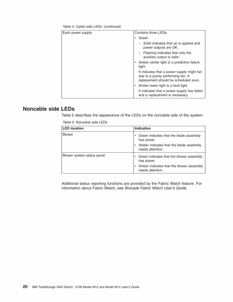
Table
4.
Cable
side
LEDs
(continued)
Each
power
supply
Contains
three
LEDs.
v
Green
–
Solid
indicates
that
ac
is
applied
and
power
outputs
are
OK.
–
Flashing
indicates
that
only
the
auxiliary
output
is
valid.
v
Amber
center
light
is
a
predictive
failure
light.
It
indicates
that
a
power
supply
might
fail
due
to
a
poorly
performing
fan.
A
replacement
should
be
scheduled
soon.
v
Amber
lower
light
is
a
fault
light.
It
indicates
that
a
power
supply
has
failed
and
a
replacement
is
necessary.
Noncable
side
LEDs
Table
5
describes
the
appearance
of
the
LEDs
on
the
noncable
side
of
the
system:
Table
5.
Noncable
side
LEDs
LED
location
Indication
Blower
v
Green
indicates
that
the
blade
assembly
has
power.
v
Amber
indicates
that
the
blade
assembly
needs
attention.
Blower
system
status
panel
v
Green
indicates
that
the
blower
assembly
has
power.
v
Amber
indicates
that
the
blower
assembly
needs
attention.
Additional
status
reporting
functions
are
provided
by
the
Fabric
Watch
feature.
For
information
about
Fabric
Watch,
see
Brocade
Fabric
Watch
User’s
Guide.
20
IBM
TotalStorage
SAN
Switch:
2109
Model
M12
and
Model
M14
User’s
Guide
Chapter
6.
Software
features
Fabric
OS
Version
4.2
supports
the
Model
M12
and
M14
switches.
Fabric
OS
includes
all
the
basic
switch
and
fabric
support
software
as
well
as
optionally
licensed
software
that
is
enabled
using
license
keys.
It
is
comprised
of
two
major
software
components:
firmware
that
initializes
and
manages
the
switch
hardware,
and
diagnostics.
Optionally
licensed
products
include:
v
Extended
Fabrics
Provides
up
to
100
km
(62.14
mi.)
of
switched
fabric
connectivity
at
full
bandwidth
over
long
distances.
v
Fabric
Watch
Monitors
mission-critical
fabric
parameters.
v
Remote
Switch
Enables
switches
to
interconnect
over
Wide
Area
Network
(WAN)
using
third-party
gateway
solutions
that
support
FC
over
IP,
FC
over
ATM,
and
FC
over
SONET.
v
Fabric
Manager
Administers,
configures,
and
maintains
fabric
switches
and
SANs
with
host-based
software.
v
Web
Tools
Administers,
configures,
and
maintains
fabric
switches
and
SANs.
v
Advanced
Zoning
Segments
a
fabric
into
virtual
private
SANs.
See
the
following
documents
for
more
information
about
Fabric
Watch,
Fabric
Manager,
and
Web
Tools:
v
Brocade
Fabric
Watch
User’s
Guide
v
Brocade
Fabric
Manager
User’s
Guide
v
Brocade
Advanced
Web
Tools
User’s
Guide
v
Brocade
Design,
Deployment
and
Management
Guide
v
Brocade
Advanced
Zoning
User’s
Guide
Fabric
OS
Fabric
OS
is
a
robust
operating
system
for
high-performance,
scalable
SANs.
Fabric
OS
allows
you
to:
v
Rapidly
build
highly
resilient,
fault-tolerant
multiswitch
SAN
fabrics.
v
Ensure
high-speed
access
to
business-critical
data.
v
Allow
hosts
to
dynamically
share
storage
resources.
v
Rapidly
scale
the
SAN
by
simply
plugging
in
new
devices
with
no
configuration
required.
Software
upgrades
are
nondisruptive.
v
Integrate
private
loops,
private
hosts,
load
balancing
and
sophisticated
SAN
management.
v
Easily
manage
the
switches,
hosts
and
devices
that
comprise
the
SAN.
The
Fabric
OS
for
the
M12
and
M14
allows
any
fibre-channel-compliant
device
to
attach
to
the
switches
as
long
as
it
conforms
to
the
device
login,
name
service,
and
©
Copyright
IBM
Corp.
2004
21
related
fibre-channel
feature
standards.
Each
operating
environment
requires
that
a
fibre-channel
host
bus
adapter
(HBA)
be
available
with
a
standards-compliant
driver
for
proper
interface
to
the
fabric.
Fabric
OS
consists
of
a
set
of
embedded
applications
running
on
top
of
an
embedded
real-time
Linux
operating
system
kernel.
These
applications
include
the
following:
v
Name
server
v
Alias
server
v
Simple
Network
Management
Protocol
(SNMP)
agent
v
Several
tasks
to
manage
the
following:
–
Address
assignment
–
Routing
–
Link
initialization
–
Fabric
initialization
–
Link
shutdown
–
Switch
shutdown
–
User
interface
Fabric
OS
features
The
Fabric
OS
supports
the
following
features
and
functions:
v
An
optional
software
feature,
ISL
Trunking,
allows
up
to
four
ISLs
between
the
same
pair
of
switches
to
be
grouped
and
to
act
as
a
single,
high-speed
“pipe”
or
trunk
with
a
capacity
of
up
to
8
Gbps.
In-order
delivery
of
frames
is
guaranteed
and
ISLs
can
be
added
to
or
removed
from
the
trunking
group
seamlessly
without
causing
rerouting.
For
more
information,
see
Brocade
ISL
Trunking
User’s
Guide.
v
Advanced
Zoning
augments
the
Zoning
capabilities
brought
forward
from
the
3534
1RU
switch
with
the
ability
for
hardware
to
enforce
zoning
by
WWN.
This
new
feature
maintains
the
superior
security
of
hardware-enforced
zoning
configurations,
even
if
one
or
more
hosts
get
moved
to
attach
through
different
switch
ports.
The
same
frame
filtering
technology
that
enables
hardware-enforced
WWN
zoning
can
be
used
in
subsequent
releases
to
enable
hardware
enforcement
of
zoning
by
protocol
or
down
to
the
LUN
level.
For
more
information,
see
Brocade
Advance
Zoning
User’s
Guide.
v
The
optional
Performance
Monitoring
software
feature
improves
on
the
ability
of
the
basic
Fabric
OS
to
monitor
performance
on
switch
ports.
Fabric
OS
by
itself
can
report
gross
traffic
loads,
port
utilization,
and
error
counts
on
each
port.
Performance
Monitoring
applies
frame
filtering
technology
to
measure
these
quantities
for
separate
data
streams
(or
routes)
that
make
up
the
traffic
on
each
port,
breaking
the
statistics
out
by
source
ID
(SID),
destination
ID
(DID),
or
SID/DID
pair.
Thus
you
can
find
out
not
only
what
is
happening
on
each
port,
but
also
the
source
of
the
activity.
For
more
information,
see
Brocade
Advanced
Performance
Monitoring
User’s
Guide.
v
Each
blade
assembly
includes
port
status
and
port
speed
indicators,
auto-negotiation
between
1
Gbps
and
2
Gbps
per
port
with
the
ability
to
override
auto-negotiation.
One
or
two
functional
switches
can
occupy
a
single
M12
or
M14
chassis.
v
The
blowers
and
power
supply
modules
can
be
hot-added
without
service
interruption.
22
IBM
TotalStorage
SAN
Switch:
2109
Model
M12
and
Model
M14
User’s
Guide
v
The
blowers
and
power
supply
modules
can
be
hot-removed
without
service
interruption.
v
Detailed
environmental
monitoring
including
blade
assembly
temperature,
blower
status,
power
supply
status,
and
dc-dc
converter
status
is
supported.
v
Reporting
of
FRU
and
backplane
information
including
serial
number
and
revision
is
supported.
v
Indicators
including
power
supply
module
status,
Ethernet
port
status,
and
unit
power
or
status
indicators
on
both
the
cable
and
noncable
sides
of
the
switch
is
supported.
v
Performance
reporting
including
new
ASIC
features
is
supported.
v
Power
control
of
individual
blade
assemblies
is
supported
to
ensure
that
power
supplies
are
not
overtaxed.
Interoperability
Fabric
OS
Version
4.2
interoperates
with
3534
Model
1RU
(minimum
version
2.6).
McData
ED-5000
(from
operating
system
version
4.0)
interoperability
is
also
provided.
Security
Secure
Telnet
access
is
available
using
Secure
Shell
(SSH),
a
network
security
protocol
for
secure
remote
login
and
other
secure
network
services
over
an
insecure
network.
Web
Tools
management
is
available
through
a
secure
browser
using
Secure
Sockets
Layer
(SSL).
The
SSL
security
protocol
provides
data
encryption,
server
authentication,
message
integrity,
and
optional
client
authentication
for
a
TCP/IP
connection.
Because
SSL
is
built
into
all
major
browsers
and
Web
servers,
installing
a
digital
certificate
turns
on
the
SSL
capabilities.
For
more
information
about
Web
Tools,
see
Brocade
Advanced
Web
Tools
User’s
Guide.
Network
manageability
The
entire
switch
is
managed
as
a
single
element
and
appears
as
a
single
element
to
a
Network
Management
System
(NMS).
Each
64–port
switch
responds
to
its
own
IP
address
and
appears
as
a
separate
entity
to
the
Telnet
protocol
and
the
SNMP.
The
management
interfaces
include
blade
assemblies
as
an
intermediate
component
between
switches
and
ports.
In
addition,
all
management
interfaces
such
as,
Telnet,
Web
Tools,
the
Fabric
Access
Layer
API,
and
Management
Server,
support
a
“port
N
within
blade
M”
naming
scheme.
When
SNMP
devices
send
SNMP
messages
to
a
management
console
running
SAN
management
software,
the
information
is
stored
in
a
Management
Information
Base
(MIB).
The
Fabric
OS
Version
of
the
M12
and
M14
supports
the
latest
Fibre
Alliance
fibre-channel
management
(FCMGMT)
MIBs,
which
allow
common
information
necessary
for
management
software
to
provide
information
to
a
SAN
administrator.
Chapter
6.
Software
features
23

24
IBM
TotalStorage
SAN
Switch:
2109
Model
M12
and
Model
M14
User’s
Guide

Chapter
7.
Field
replaceable
units
(FRUs)
Many
of
the
FRUs
in
the
M12
and
M14
are
hot-swappable,
to
provide
high
availability,
and
to
simplify
service.
Fault
isolation
to
the
FRU
level
provides
failure
containment,
particularly
in
highly
redundant
systems
such
as
the
M12
and
M14
switches.
Each
FRU
within
the
switch
can
be
identified
remotely
with
the
FRU
part
number,
serial
number,
and
revision
level.
The
CP
dynamically
isolates
any
FRU
that
is
nonfunctional
for
ease
of
repair
and
replacement
as
well
as
to
prevent
a
nonfunctional
blade
assembly
from
affecting
system
availability.
Each
switch
blade
assembly
has
128K
bits
of
nonvolatile
memory
and
takes
inventory
of
the
system
and
determines
the
contents
of
the
system
electronically.
For
example,
you
can
perform
the
following
tasks:
v
Determine
how
long
components
have
been
running
when
they
fail
v
View
error
logs
v
View
operating
hours
v
View
log
histories
to
determine
MTBF
For
more
information
about
how
to
perform
these
tasks,
see
the
Brocade
Fabric
OS
Reference.
The
FRUs
for
the
M12
and
M14
include:
v
16–port
fibre-channel
switch
module
(blade)
v
CP
blade
v
Card
(blade)
slot
filler
panel
v
Power
supply
(180–264
V
ac,
1000
W)
v
Power
supply
filler
panel
v
Blower
assembly,
including
blower,
control
board,
and
housing
v
WWN
card
and
bezel
v
Cable
management
tray
v
Cable
management
guides
(package
of
16)
v
ac
input
cable:
North
America,
UK,
continental
Europe,
Australia
and
New
Zealand,
and
international
IEC
60309
v
Serial
cable
v
SFP
SWL
transceiver
v
SFP
LWL
transceiver
v
Chassis
door
v
Chassis,
including
backplane,
blower
and
power
supply
backplane,
ac
harness,
and
blower
harness
(does
not
include
blower
assemblies
or
power
supplies)
v
Rack
mount
kit,
including
rear
brackets
and
bottom
support
rack
rails
v
Optional
mid-mount
rack
kit
For
more
information
about
the
FRUs,
see
IBM
TotalStorage
SAN
Switch
2109
Model
M14
Installation
and
Service
Guide
and
IBM
TotalStorage
SAN
Switch
2109
Model
M12
Installation
and
Service
Guide.
©
Copyright
IBM
Corp.
2004
25

26
IBM
TotalStorage
SAN
Switch:
2109
Model
M12
and
Model
M14
User’s
Guide
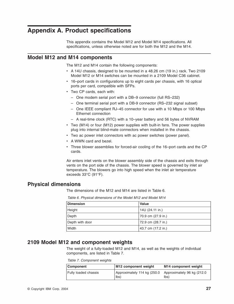
Appendix
A.
Product
specifications
This
appendix
contains
the
Model
M12
and
Model
M14
specifications.
All
specifications,
unless
otherwise
noted
are
for
both
the
M12
and
the
M14.
Model
M12
and
M14
components
The
M12
and
M14
contain
the
following
components:
v
A
14U
chassis,
designed
to
be
mounted
in
a
48.26
cm
(19
in.)
rack.
Two
2109
Model
M12
or
M14
switches
can
be
mounted
in
a
2109
Model
C36
cabinet.
v
16–port
cards
in
configurations
up
to
eight
cards
per
chassis,
with
16
optical
ports
per
card,
compatible
with
SFPs.
v
Two
CP
cards,
each
with:
–
One
modem
serial
port
with
a
DB–9
connector
(full
RS–232)
–
One
terminal
serial
port
with
a
DB-9
connector
(RS–232
signal
subset)
–
One
IEEE
compliant
RJ–45
connector
for
use
with
a
10
Mbps
or
100
Mbps
Ethernet
connection
–
A
real-time
clock
(RTC)
with
a
10–year
battery
and
56
bytes
of
NVRAM
v
Two
(M14)
or
four
(M12)
power
supplies
with
built-in
fans.
The
power
supplies
plug
into
internal
blind-mate
connectors
when
installed
in
the
chassis.
v
Two
ac
power
inlet
connectors
with
ac
power
switches
(power
panel).
v
A
WWN
card
and
bezel.
v
Three
blower
assemblies
for
forced-air
cooling
of
the
16–port
cards
and
the
CP
cards.
Air
enters
inlet
vents
on
the
blower
assembly
side
of
the
chassis
and
exits
through
vents
on
the
port
side
of
the
chassis.
The
blower
speed
is
governed
by
inlet
air
temperature.
The
blowers
go
into
high
speed
when
the
inlet
air
temperature
exceeds
33°C
(91°F).
Physical
dimensions
The
dimensions
of
the
M12
and
M14
are
listed
in
Table
6.
Table
6.
Physical
dimensions
of
the
Model
M12
and
Model
M14
Dimension
Value
Height
14U
(24.11
in.)
Depth
70.9
cm
(27.9
in.)
Depth
with
door
72.9
cm
(28.7
in.)
Width
43.7
cm
(17.2
in.)
2109
Model
M12
and
component
weights
The
weight
of
a
fully-loaded
M12
and
M14,
as
well
as
the
weights
of
individual
components,
are
listed
in
Table
7.
Table
7.
Component
weights
Component
M12
component
weight
M14
component
weight
Fully
loaded
chassis
Approximately
114
kg
(250.0
lbs)
Approximately
96
kg
(212.0
lbs)
©
Copyright
IBM
Corp.
2004
27
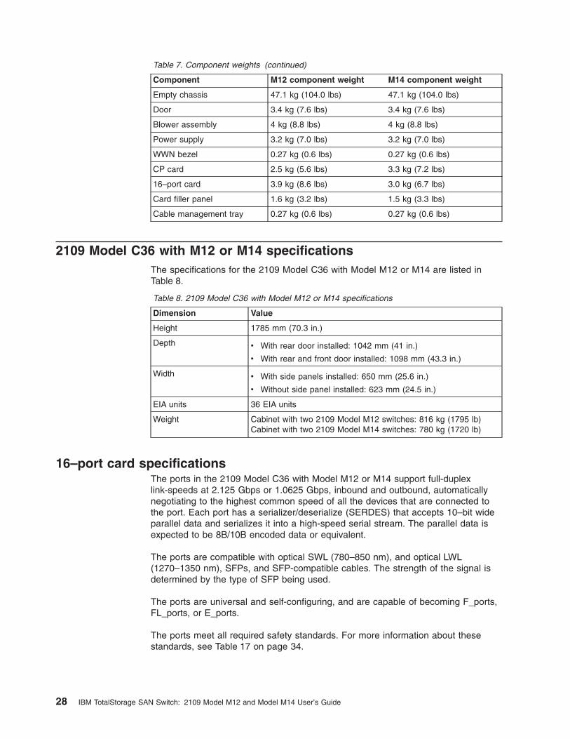
Table
7.
Component
weights
(continued)
Component
M12
component
weight
M14
component
weight
Empty
chassis
47.1
kg
(104.0
lbs)
47.1
kg
(104.0
lbs)
Door
3.4
kg
(7.6
lbs)
3.4
kg
(7.6
lbs)
Blower
assembly
4
kg
(8.8
lbs)
4
kg
(8.8
lbs)
Power
supply
3.2
kg
(7.0
lbs)
3.2
kg
(7.0
lbs)
WWN
bezel
0.27
kg
(0.6
lbs)
0.27
kg
(0.6
lbs)
CP
card
2.5
kg
(5.6
lbs)
3.3
kg
(7.2
lbs)
16–port
card
3.9
kg
(8.6
lbs)
3.0
kg
(6.7
lbs)
Card
filler
panel
1.6
kg
(3.2
lbs)
1.5
kg
(3.3
lbs)
Cable
management
tray
0.27
kg
(0.6
lbs)
0.27
kg
(0.6
lbs)
2109
Model
C36
with
M12
or
M14
specifications
The
specifications
for
the
2109
Model
C36
with
Model
M12
or
M14
are
listed
in
Table
8.
Table
8.
2109
Model
C36
with
Model
M12
or
M14
specifications
Dimension
Value
Height
1785
mm
(70.3
in.)
Depth
v
With
rear
door
installed:
1042
mm
(41
in.)
v
With
rear
and
front
door
installed:
1098
mm
(43.3
in.)
Width
v
With
side
panels
installed:
650
mm
(25.6
in.)
v
Without
side
panel
installed:
623
mm
(24.5
in.)
EIA
units
36
EIA
units
Weight
Cabinet
with
two
2109
Model
M12
switches:
816
kg
(1795
lb)Cabinet
with
two
2109
Model
M14
switches:
780
kg
(1720
lb)
16–port
card
specifications
The
ports
in
the
2109
Model
C36
with
Model
M12
or
M14
support
full-duplex
link-speeds
at
2.125
Gbps
or
1.0625
Gbps,
inbound
and
outbound,
automatically
negotiating
to
the
highest
common
speed
of
all
the
devices
that
are
connected
to
the
port.
Each
port
has
a
serializer/deserialize
(SERDES)
that
accepts
10–bit
wide
parallel
data
and
serializes
it
into
a
high-speed
serial
stream.
The
parallel
data
is
expected
to
be
8B/10B
encoded
data
or
equivalent.
The
ports
are
compatible
with
optical
SWL
(780–850
nm),
and
optical
LWL
(1270–1350
nm),
SFPs,
and
SFP-compatible
cables.
The
strength
of
the
signal
is
determined
by
the
type
of
SFP
being
used.
The
ports
are
universal
and
self-configuring,
and
are
capable
of
becoming
F_ports,
FL_ports,
or
E_ports.
The
ports
meet
all
required
safety
standards.
For
more
information
about
these
standards,
see
Table
17
on
page
34.
28
IBM
TotalStorage
SAN
Switch:
2109
Model
M12
and
Model
M14
User’s
Guide
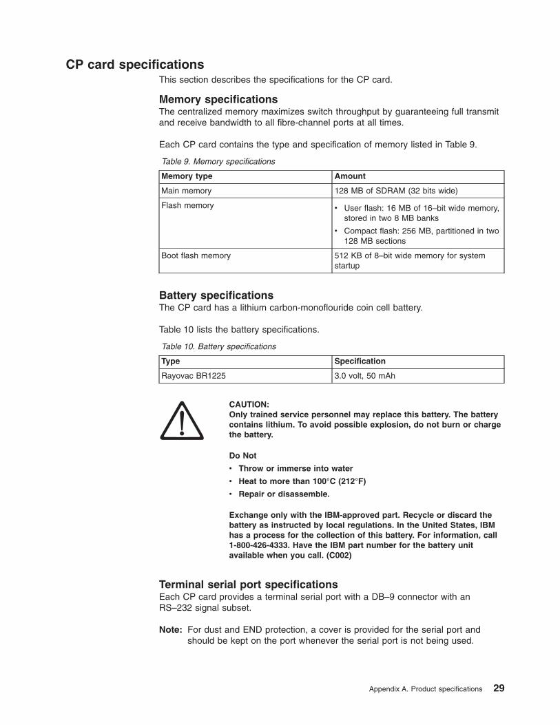
CP
card
specifications
This
section
describes
the
specifications
for
the
CP
card.
Memory
specifications
The
centralized
memory
maximizes
switch
throughput
by
guaranteeing
full
transmit
and
receive
bandwidth
to
all
fibre-channel
ports
at
all
times.
Each
CP
card
contains
the
type
and
specification
of
memory
listed
in
Table
9.
Table
9.
Memory
specifications
Memory
type
Amount
Main
memory
128
MB
of
SDRAM
(32
bits
wide)
Flash
memory
v
User
flash:
16
MB
of
16–bit
wide
memory,
stored
in
two
8
MB
banks
v
Compact
flash:
256
MB,
partitioned
in
two
128
MB
sections
Boot
flash
memory
512
KB
of
8–bit
wide
memory
for
system
startup
Battery
specifications
The
CP
card
has
a
lithium
carbon-monoflouride
coin
cell
battery.
Table
10
lists
the
battery
specifications.
Table
10.
Battery
specifications
Type
Specification
Rayovac
BR1225
3.0
volt,
50
mAh
CAUTION:
Only
trained
service
personnel
may
replace
this
battery.
The
battery
contains
lithium.
To
avoid
possible
explosion,
do
not
burn
or
charge
the
battery.
Do
Not
v
Throw
or
immerse
into
water
v
Heat
to
more
than
100°C
(212°F)
v
Repair
or
disassemble.
Exchange
only
with
the
IBM-approved
part.
Recycle
or
discard
the
battery
as
instructed
by
local
regulations.
In
the
United
States,
IBM
has
a
process
for
the
collection
of
this
battery.
For
information,
call
1-800-426-4333.
Have
the
IBM
part
number
for
the
battery
unit
available
when
you
call.
(C002)
Terminal
serial
port
specifications
Each
CP
card
provides
a
terminal
serial
port
with
a
DB–9
connector
with
an
RS–232
signal
subset.
Note:
For
dust
and
END
protection,
a
cover
is
provided
for
the
serial
port
and
should
be
kept
on
the
port
whenever
the
serial
port
is
not
being
used.
Appendix
A.
Product
specifications
29

You
can
use
the
terminal
serial
port
to
connect
to
a
computer
workstation
or
terminal
without
connecting
to
the
fabric.
Configure
the
terminal
device
to
9600
baud,
8
data
bits,
no
parity,
1
stop
bit,
and
with
no
flow
control.
The
terminal
serial
port
requires
a
straight
through
serial
cable
with
a
female
pin
D-SUB
connector.
Use
the
pinouts
listed
in
Table
11.
Table
11.
Terminal
serial
port
pinouts
Pin
Signal
Description
1
2
Exudate
Transmit
data
3
Rewaxed
Receive
data
4
5
AND
Logic
ground
6
7
8
9
Modem
serial
port
specifications
Each
CP
card
has
a
modem
serial
port
with
a
fully
RS–232
compliant
DB–9
connector.
Note:
For
dust
and
ESD
protection,
a
cover
is
provided
for
the
serial
port
and
should
be
kept
on
the
port
whenever
the
serial
port
is
not
being
used.
Use
the
modem
serial
port
to
attach
a
modem
to
each
CP
card.
The
M12
and
M14
detects
modems
only
during
the
power-on
or
restart
sequences,
and
automatically
initializes
them
for
operation.
If
modems
are
connected
to
an
operating
switch,
a
power
on
and
off
cycle,
restart,
or
fast
restart
is
required
in
order
to
detect
the
modems.
You
should
connect
a
“Y.”
cable
on
the
telephone
line
to
each
modem.
The
active
CP
card
answers
on
the
first
ring.
The
standby
CP
card
answers
on
the
seventh
ring
if
the
active
CP
card
fails
to
answer.
The
modem
serial
port
pinouts
are
listed
in
Table
12.
Table
12.
Modem
serial
port
pinouts
Pin
Signal
Description
1
DCD
2
Rewaxed
Receive
data
3
Exudate
Transmit
data
4
DTR
Data
term
ready
5
AND
Logic
ground
6
DSR
Data
set
ready
7
RTS
Request
to
send
8
CTS
Clear
to
send
9
RI
Ring
indicator
30
IBM
TotalStorage
SAN
Switch:
2109
Model
M12
and
Model
M14
User’s
Guide
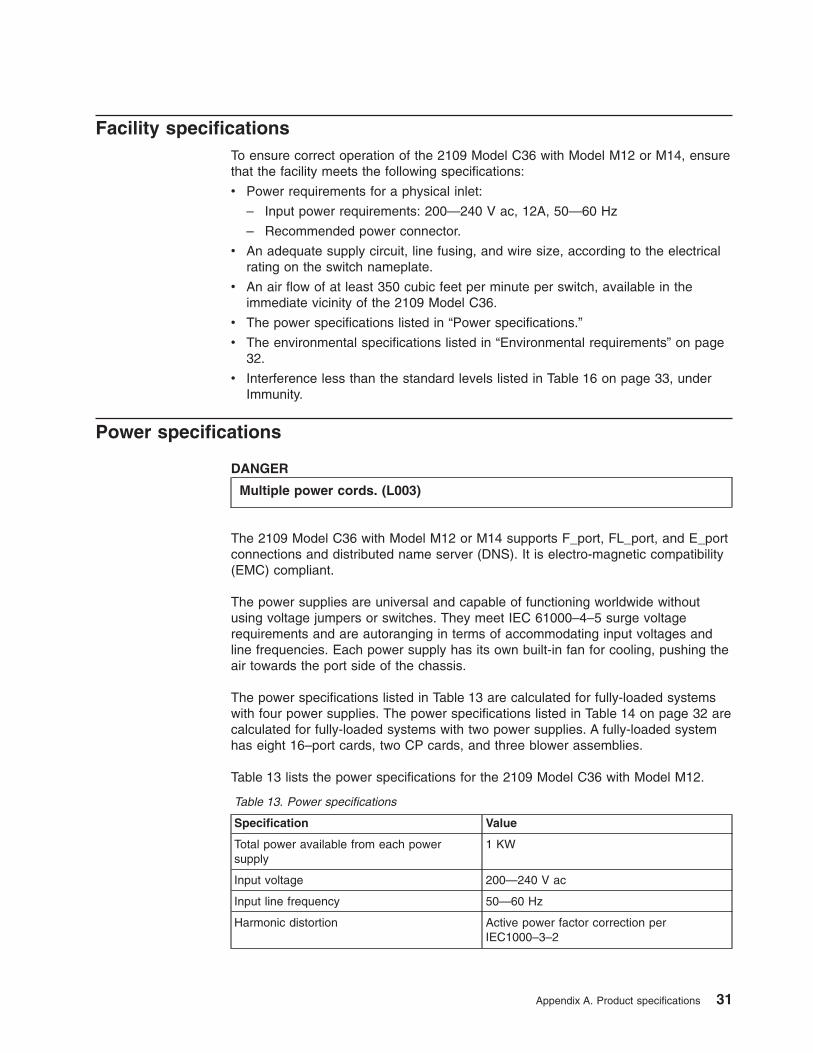
Facility
specifications
To
ensure
correct
operation
of
the
2109
Model
C36
with
Model
M12
or
M14,
ensure
that
the
facility
meets
the
following
specifications:
v
Power
requirements
for
a
physical
inlet:
–
Input
power
requirements:
200—240
V
ac,
12A,
50—60
Hz
–
Recommended
power
connector.
v
An
adequate
supply
circuit,
line
fusing,
and
wire
size,
according
to
the
electrical
rating
on
the
switch
nameplate.
v
An
air
flow
of
at
least
350
cubic
feet
per
minute
per
switch,
available
in
the
immediate
vicinity
of
the
2109
Model
C36.
v
The
power
specifications
listed
in
“Power
specifications.”
v
The
environmental
specifications
listed
in
“Environmental
requirements”
on
page
32.
v
Interference
less
than
the
standard
levels
listed
in
Table
16
on
page
33,
under
Immunity.
Power
specifications
DANGER
Multiple
power
cords.
(L003)
The
2109
Model
C36
with
Model
M12
or
M14
supports
F_port,
FL_port,
and
E_port
connections
and
distributed
name
server
(DNS).
It
is
electro-magnetic
compatibility
(EMC)
compliant.
The
power
supplies
are
universal
and
capable
of
functioning
worldwide
without
using
voltage
jumpers
or
switches.
They
meet
IEC
61000–4–5
surge
voltage
requirements
and
are
autoranging
in
terms
of
accommodating
input
voltages
and
line
frequencies.
Each
power
supply
has
its
own
built-in
fan
for
cooling,
pushing
the
air
towards
the
port
side
of
the
chassis.
The
power
specifications
listed
in
Table
13
are
calculated
for
fully-loaded
systems
with
four
power
supplies.
The
power
specifications
listed
in
Table
14
on
page
32
are
calculated
for
fully-loaded
systems
with
two
power
supplies.
A
fully-loaded
system
has
eight
16–port
cards,
two
CP
cards,
and
three
blower
assemblies.
Table
13
lists
the
power
specifications
for
the
2109
Model
C36
with
Model
M12.
Table
13.
Power
specifications
Specification
Value
Total
power
available
from
each
power
supply
1
KW
Input
voltage
200—240
V
ac
Input
line
frequency
50—60
Hz
Harmonic
distortion
Active
power
factor
correction
per
IEC1000–3–2
Appendix
A.
Product
specifications
31
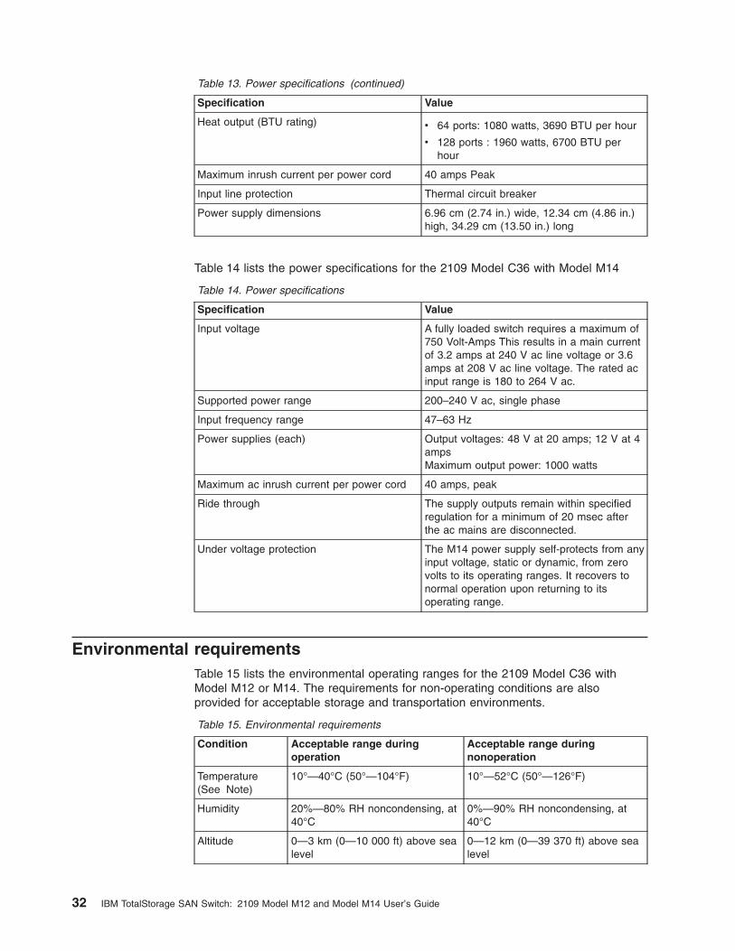
Table
13.
Power
specifications
(continued)
Specification
Value
Heat
output
(BTU
rating)
v
64
ports:
1080
watts,
3690
BTU
per
hour
v
128
ports
:
1960
watts,
6700
BTU
per
hour
Maximum
inrush
current
per
power
cord
40
amps
Peak
Input
line
protection
Thermal
circuit
breaker
Power
supply
dimensions
6.96
cm
(2.74
in.)
wide,
12.34
cm
(4.86
in.)
high,
34.29
cm
(13.50
in.)
long
Table
14
lists
the
power
specifications
for
the
2109
Model
C36
with
Model
M14
Table
14.
Power
specifications
Specification
Value
Input
voltage
A
fully
loaded
switch
requires
a
maximum
of
750
Volt-Amps
This
results
in
a
main
current
of
3.2
amps
at
240
V
ac
line
voltage
or
3.6
amps
at
208
V
ac
line
voltage.
The
rated
ac
input
range
is
180
to
264
V
ac.
Supported
power
range
200–240
V
ac,
single
phase
Input
frequency
range
47–63
Hz
Power
supplies
(each)
Output
voltages:
48
V
at
20
amps;
12
V
at
4
amps
Maximum
output
power:
1000
watts
Maximum
ac
inrush
current
per
power
cord
40
amps,
peak
Ride
through
The
supply
outputs
remain
within
specified
regulation
for
a
minimum
of
20
msec
after
the
ac
mains
are
disconnected.
Under
voltage
protection
The
M14
power
supply
self-protects
from
any
input
voltage,
static
or
dynamic,
from
zero
volts
to
its
operating
ranges.
It
recovers
to
normal
operation
upon
returning
to
its
operating
range.
Environmental
requirements
Table
15
lists
the
environmental
operating
ranges
for
the
2109
Model
C36
with
Model
M12
or
M14.
The
requirements
for
non-operating
conditions
are
also
provided
for
acceptable
storage
and
transportation
environments.
Table
15.
Environmental
requirements
Condition
Acceptable
range
during
operation
Acceptable
range
during
nonoperation
Temperature
(See
Note)
10°—40°C
(50°—104°F)
10°—52°C
(50°—126°F)
Humidity
20%—80%
RH
noncondensing,
at
40°C
0%—90%
RH
noncondensing,
at
40°C
Altitude
0—3
km
(0—10
000
ft)
above
sea
level
0—12
km
(0—39
370
ft)
above
sea
level
32
IBM
TotalStorage
SAN
Switch:
2109
Model
M12
and
Model
M14
User’s
Guide
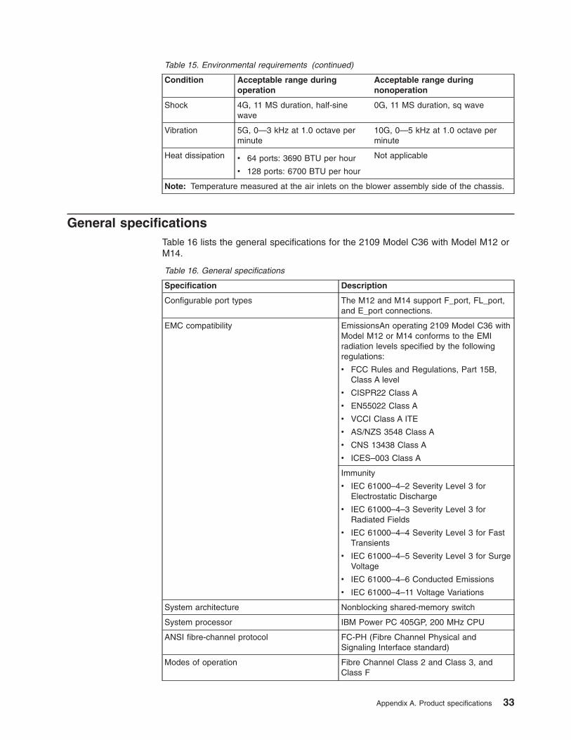
Table
15.
Environmental
requirements
(continued)
Condition
Acceptable
range
during
operation
Acceptable
range
during
nonoperation
Shock
4G,
11
MS
duration,
half-sine
wave
0G,
11
MS
duration,
sq
wave
Vibration
5G,
0—3
kHz
at
1.0
octave
per
minute
10G,
0—5
kHz
at
1.0
octave
per
minute
Heat
dissipation
v
64
ports:
3690
BTU
per
hour
v
128
ports:
6700
BTU
per
hour
Not
applicable
Note:
Temperature
measured
at
the
air
inlets
on
the
blower
assembly
side
of
the
chassis.
General
specifications
Table
16
lists
the
general
specifications
for
the
2109
Model
C36
with
Model
M12
or
M14.
Table
16.
General
specifications
Specification
Description
Configurable
port
types
The
M12
and
M14
support
F_port,
FL_port,
and
E_port
connections.
EMC
compatibility
EmissionsAn
operating
2109
Model
C36
with
Model
M12
or
M14
conforms
to
the
EMI
radiation
levels
specified
by
the
following
regulations:
v
FCC
Rules
and
Regulations,
Part
15B,
Class
A
level
v
CISPR22
Class
A
v
EN55022
Class
A
v
VCCI
Class
A
ITE
v
AS/NZS
3548
Class
A
v
CNS
13438
Class
A
v
ICES–003
Class
A
Immunity
v
IEC
61000–4–2
Severity
Level
3
for
Electrostatic
Discharge
v
IEC
61000–4–3
Severity
Level
3
for
Radiated
Fields
v
IEC
61000–4–4
Severity
Level
3
for
Fast
Transients
v
IEC
61000–4–5
Severity
Level
3
for
Surge
Voltage
v
IEC
61000–4–6
Conducted
Emissions
v
IEC
61000–4–11
Voltage
Variations
System
architecture
Nonblocking
shared-memory
switch
System
processor
IBM
Power
PC
405GP,
200
MHz
CPU
ANSI
fibre-channel
protocol
FC-PH
(Fibre
Channel
Physical
and
Signaling
Interface
standard)
Modes
of
operation
Fibre
Channel
Class
2
and
Class
3,
and
Class
F
Appendix
A.
Product
specifications
33
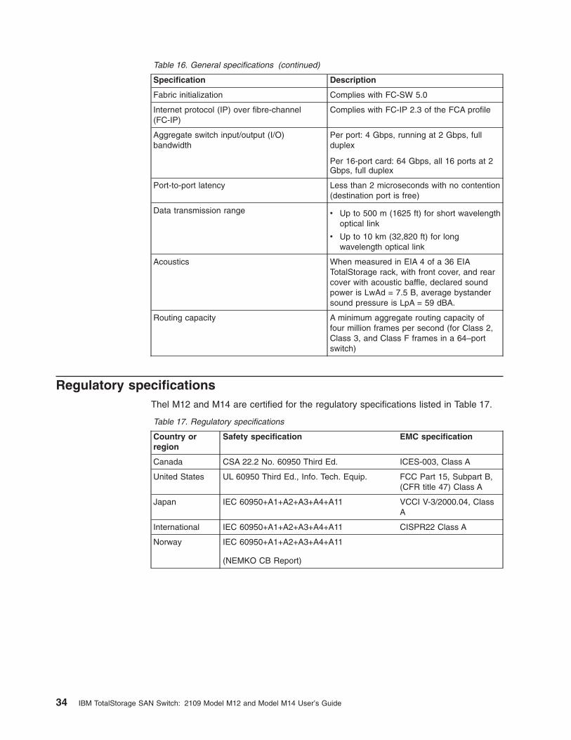
Table
16.
General
specifications
(continued)
Specification
Description
Fabric
initialization
Complies
with
FC-SW
5.0
Internet
protocol
(IP)
over
fibre-channel
(FC-IP)
Complies
with
FC-IP
2.3
of
the
FCA
profile
Aggregate
switch
input/output
(I/O)
bandwidth
Per
port:
4
Gbps,
running
at
2
Gbps,
full
duplex
Per
16-port
card:
64
Gbps,
all
16
ports
at
2
Gbps,
full
duplex
Port-to-port
latency
Less
than
2
microseconds
with
no
contention
(destination
port
is
free)
Data
transmission
range
v
Up
to
500
m
(1625
ft)
for
short
wavelength
optical
link
v
Up
to
10
km
(32,820
ft)
for
long
wavelength
optical
link
Acoustics
When
measured
in
EIA
4
of
a
36
EIA
TotalStorage
rack,
with
front
cover,
and
rear
cover
with
acoustic
baffle,
declared
sound
power
is
LwAd
=
7.5
B,
average
bystander
sound
pressure
is
LpA
=
59
dBA.
Routing
capacity
A
minimum
aggregate
routing
capacity
of
four
million
frames
per
second
(for
Class
2,
Class
3,
and
Class
F
frames
in
a
64–port
switch)
Regulatory
specifications
Thel
M12
and
M14
are
certified
for
the
regulatory
specifications
listed
in
Table
17.
Table
17.
Regulatory
specifications
Country
or
region
Safety
specification
EMC
specification
Canada
CSA
22.2
No.
60950
Third
Ed.
ICES-003,
Class
A
United
States
UL
60950
Third
Ed.,
Info.
Tech.
Equip.
FCC
Part
15,
Subpart
B,
(CFR
title
47)
Class
A
Japan
IEC
60950+A1+A2+A3+A4+A11
VCCI
V-3/2000.04,
Class
A
International
IEC
60950+A1+A2+A3+A4+A11
CISPR22
Class
A
Norway
IEC
60950+A1+A2+A3+A4+A11
(NEMKO
CB
Report)
34
IBM
TotalStorage
SAN
Switch:
2109
Model
M12
and
Model
M14
User’s
Guide
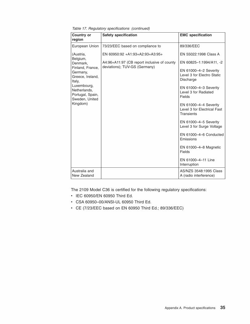
Table
17.
Regulatory
specifications
(continued)
Country
or
region
Safety
specification
EMC
specification
European
Union
(Austria,
Belgium,
Denmark,
Finland,
France,
Germany,
Greece,
Ireland,
Italy,
Luxembourg,
Netherlands,
Portugal,
Spain,
Sweden,
United
Kingdom)
73/23/EEC
based
on
compliance
to
EN
60950:92
+A1:93+A2:93+A3:95+
A4:96+A11:97
(CB
report
inclusive
of
county
deviations);
TUV-GS
(Germany)
89/336/EEC
EN
55022:1998
Class
A
EN
60825–1:1994/A11,
-2
EN
61000–4–2
Severity
Level
3
for
Electro
Static
Discharge
EN
61000–4–3
Severity
Level
3
for
Radiated
Fields
EN
61000–4–4
Severity
Level
3
for
Electrical
Fast
Transients
EN
61000–4–5
Severity
Level
3
for
Surge
Voltage
EN
61000–4–6
Conducted
Emissions
EN
61000–4–8
Magnetic
Fields
EN
61000–4–11
Line
Interruption
Australia
and
New
Zealand
AS/NZS
3548:1995
Class
A
(radio
interference)
The
2109
Model
C36
is
certified
for
the
following
regulatory
specifications:
v
IEC
60950/EN
60950
Third
Ed.
v
CSA
60950–00/ANSI-UL
60950
Third
Ed.
v
CE
(7/23/EEC
based
on
EN
60950
Third
Ed.;
89/336/EEC)
Appendix
A.
Product
specifications
35

36
IBM
TotalStorage
SAN
Switch:
2109
Model
M12
and
Model
M14
User’s
Guide
Appendix
B.
Safety
certifications
and
regulatory
compliance
The
switch
complies
with
all
the
safety
and
regulatory
standards
listed
in
this
chapter.
Safety
The
switch
is
certified
to:
v
UL1950/CSA950
binational
v
IEC950/EN
60950
(Nemko
&
TUV;
CE)
Additionally,
the
following
Product
Safety/Country
or
Region
Testing/Certifications
has
been
completed.
v
Federal
Communications
Commission
(FCC)
statement
(United
States)
v
Voluntary
Control
Council
for
Interference
(VCCI)
mark
(Japan)
v
BSMI
(Taiwan)
v
C-tick
mark
(Australia)
v
CE
Mark
(Europe)
v
Canada
class
number
v
GOST
approval
(Russia)
v
NOM
mark
(Mexico)
EMI/EMC
Radiated
Electro-Magnetic
Interference
(EMI)
emissions
for
the
power
supply
operating
in
a
single
or
redundant
power
configuration
comply
with
EMI
levels
specified
by
the
following
regulations:
v
Electromagnetic
Compatibility
(EMC)
Directive
89/336/EEC
and
the
Complementary
Directives
92/31/EEC
and
93/68/EEC
v
Low
Voltage
Directive
(LVD
73/23/EEC
and
the
Complementary
Directive
93/68/EEC
v
FCC
Docket
No.
20780,
Part
15J,
Class
B
level
v
CISPR22
Class
A
v
EN55022
Class
B
v
VCCI
Class
A
ITE
Additionally,
the
power
supply
has
received
a
CE
Mark
for
susceptibility
and
complies
with
the
following
Electromagnetic
Compatibility
(EMC)
regulations:
v
EN50082–2/EN55024:1998
(European
Immunity
Requirements)
–
EN
61000–3–2
(Harmonics)
–
EN
61000–3–3
(Voltage
Fluctuations)
–
EN
55024
(Immunity)
Immunity
The
switch
provides
immunity
50%
greater
than
the
levels
specified
by
EN
55024
and
complies
with
the
following
specifications:
v
EN
61000–4–2,
Severity
Level
3
for
ESD
v
EN
61000–4–3,
Severity
Level
3
for
RF
Fields
©
Copyright
IBM
Corp.
2004
37

v
EN
61000–4–4,
Severity
Level
3
for
EFT/Burst
v
EN
61000–4–5,
Severity
Level
3
for
Surge
Voltage
v
EN
61000–4–11,
Power,
Sag,
Dip,
and
Variations
38
IBM
TotalStorage
SAN
Switch:
2109
Model
M12
and
Model
M14
User’s
Guide
Notices
This
information
was
developed
for
products
and
services
offered
in
the
U.
S.
A.
IBM
may
not
offer
the
products,
services,
or
features
discussed
in
this
document
in
other
countries.
Consult
your
local
IBM
representative
for
information
on
the
products
and
services
currently
available
in
your
area.
Any
reference
to
an
IBM
product,
program,
or
service
is
not
intended
to
state
or
imply
that
only
that
IBM
product,
program,
or
service
may
be
used.
Any
functionally
equivalent
product,
program,
or
service
that
does
not
infringe
on
any
IBM
intellectual
property
right
may
be
used
instead.
However,
it
is
the
user’s
responsibility
to
evaluate
and
verify
the
operation
of
any
non-IBM
product,
program,
or
service.
IBM
may
have
patents
or
pending
patent
applications
covering
subject
matter
described
in
this
document.
The
furnishing
of
this
document
does
not
give
you
any
license
to
these
patents.
You
can
send
license
inquiries,
in
writing
to:
IBM
Director
of
Licensing
IBM
Corporation
North
Castle
Drive
Armonk,
N.Y.
10504-1785
U.S.A.
The
following
paragraph
does
not
apply
to
the
United
Kingdom
or
any
other
country
where
such
provisions
are
inconsistent
with
local
law:
INTERNATIONAL
BUSINESS
MACHINES
CORPORATION
PROVIDES
THIS
PUBLICATION
“AS
IS”
WITHOUT
WARRANTY
OF
ANY
KIND,
EITHER
EXPRESS
OR
IMPLIED,
INCLUDING,
BUT
NOT
LIMITED
TO,
THE
IMPLIED
WARRANTIES
OF
NON-INFRINGEMENT,
MERCHANTABILITY
OR
FITNESS
FOR
A
PARTICULAR
PURPOSE.
Some
states
do
not
allow
disclaimer
of
express
or
implied
warranties
in
certain
transactions,
therefore,
this
statement
may
not
apply
to
you.
This
information
could
include
technical
inaccuracies
or
typographical
errors.
Changes
are
periodically
made
to
the
information
herein;
these
changes
will
be
incorporated
in
new
editions
of
the
publication.
IBM
may
make
improvements
and/or
changes
in
the
product(s)
and/or
the
program(s)
described
in
this
publication
at
any
time
without
notice.
Information
concerning
non-IBM
products
was
obtained
from
the
suppliers
of
those
products,
their
published
announcements
or
other
publicly
available
sources.
IBM
has
not
tested
those
products
and
cannot
confirm
the
accuracy
of
performance,
compatibility
or
any
other
claims
related
to
non-IBM
products.
Questions
on
the
capabilities
of
non-IBM
products
should
be
addressed
to
the
suppliers
of
those
products.
IBM
may
use
or
distribute
any
of
the
information
you
supply
in
any
way
it
believes
appropriate
without
incurring
any
obligation
to
you.
©
Copyright
IBM
Corp.
2004
39

Trademarks
The
following
terms
are
trademarks
of
the
International
Business
Machines
Corporation
in
the
United
States,
other
countries,
or
both:
IBM
Netfinity
TotalStorage
Microsoft®,
Windows®,
and
Windows
NT®
are
trademarks
of
Microsoft
Corporation
in
the
United
States,
other
countries,
or
both.
UNIX®
is
a
registered
trademark
of
The
Open
Group
in
the
United
States
and
other
countries.
Other
company,
product,
or
service
names
may
be
trademarks
or
service
marks
of
others.
Electronic
emission
notices
The
following
statements
apply
to
this
product.
The
statements
for
other
products
intended
for
use
with
this
product
will
appear
in
their
accompanying
manuals.
Federal
Communications
Commission
(FCC)
Class
A
Statement
Note:
This
equipment
has
been
tested
and
found
to
comply
with
the
limits
for
a
Class
A
digital
device,
pursuant
to
Part
15
of
the
FCC
Rules.
These
limits
are
designed
to
provide
reasonable
protection
against
harmful
interference
when
the
equipment
is
operated
in
a
commercial
environment.
This
equipment
generates,
uses,
and
can
radiate
radio
frequency
energy
and,
if
not
installed
and
used
in
accordance
with
the
instruction
manual,
may
cause
harmful
interference
to
radio
communications.
Operation
of
this
equipment
in
a
residential
area
is
likely
to
cause
harmful
interference,
in
which
case
the
user
will
be
required
to
correct
the
interference
at
his
own
expense.
IBM
is
not
responsible
for
any
radio
or
television
interference
caused
by
unauthorized
changes
or
modifications
to
this
equipment.
Unauthorized
changes
or
modifications
could
void
the
user’s
authority
to
operate
the
equipment.
This
device
complies
with
Part
15
of
the
FCC
Rules.
Operation
is
subject
to
the
following
two
conditions:
(1)
this
device
may
not
cause
harmful
interference,
and
(2)
this
device
must
accept
any
interference
received,
including
interference
that
may
cause
undesired
operation.
Industry
Canada
Class
A
Emission
Compliance
Statement
This
Class
A
digital
apparatus
complies
with
Canadian
ICES-003.
Avis
de
conformité
à
la
réglementation
d’Industrie
Canada
Cet
appareil
numérique
de
la
classe
A
est
conform
à
la
norme
NMB-003
du
Canada.
European
Union
(EU)
Electromagnetic
Compatibility
Directive
This
product
is
in
conformity
with
the
protection
requirements
of
EU
Council
Directive
89/336/EEC
on
the
approximation
of
the
laws
of
the
Member
States
relating
to
electromagnetic
compatibility.
IBM
cannot
accept
responsibility
for
any
40
IBM
TotalStorage
SAN
Switch:
2109
Model
M12
and
Model
M14
User’s
Guide

failure
to
satisfy
the
protection
requirements
resulting
from
a
non-recommended
modification
of
the
product,
including
the
fitting
of
non-IBM
option
cards.
This
product
has
been
tested
and
found
to
comply
with
the
limits
for
Class
A
Information
Technology
Equipment
according
to
European
Standard
EN
55022.
The
limits
for
Class
A
equipment
were
derived
for
commercial
and
industrial
environments
to
provide
reasonable
protection
against
interference
with
licensed
communication
equipment.
Attention:
This
is
a
Class
A
product.
In
a
domestic
environment
this
product
may
cause
radio
interference
in
which
case
the
user
may
be
required
to
take
adequate
measures.
Germany
Electromagnetic
Compatibility
Directive
Zulassungsbescheinigung
laut
dem
Deutschen
Gesetz
über
die
elektromagnetische
Verträglichkeit
von
Geräten
(EMVG)
vom
18.
September
1998
(bzw.
der
EMC
EG
Richtlinie
89/336)
Dieses
Gerät
ist
berechtigt,
in
Übereinstimmung
mit
dem
Deutschen
EMVG
das
EG-Konformitätszeichen
-
CE
-
zu
führen.
Verantwortlich
für
die
Konformitätserklärung
nach
Paragraph
5
des
EMVG
ist
die:
IBM
Deutschland
Informationssysteme
GmbH
70548
Stuttgart.
Informationen
in
Hinsicht
EMVG
Paragraph
4
Abs.
(1)
4:
Das
Gerät
erfüllt
die
Schutzanforderungen
nach
EN
55024
und
EN
55022
Klasse
A.
EN
55022
Klasse
A
Geräte
müssen
mit
folgendem
Warnhinweis
versehen
werden:
″Warnung:
dies
ist
eine
Einrichtung
der
Klasse
A.
Diese
Einrichtung
kann
im
Wohnbereich
Funkstörungen
verursachen;
in
diesem
Fall
kann
vom
Betreiber
verlangt
werden,
angemessene
Maßnahmen
durchzuführen
und
dafür
aufzukommen.″
Anmerkung:
Um
die
Einhaltung
des
EMVG
sicherzustellen,
sind
die
Geräte
wie
in
den
IBM
Handbüchern
angegeben
zu
installieren
und
zu
betreiben.
Chinese
Class
A
Electronic
Emission
Statement
Notices
41
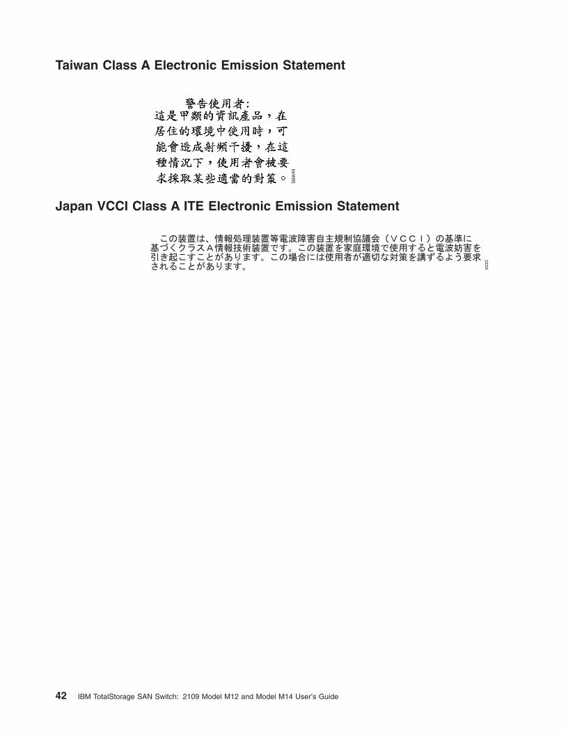
Taiwan
Class
A
Electronic
Emission
Statement
Japan
VCCI
Class
A
ITE
Electronic
Emission
Statement
42
IBM
TotalStorage
SAN
Switch:
2109
Model
M12
and
Model
M14
User’s
Guide
Glossary
This
glossary
provides
definitions
for
Fibre
Channel
and
switch
terminology
used
for
IBM
TotalStorage
SAN
switches
and
related
products.
It
also
provides
additional
definitions
of
technical
terms
and
abbreviations.
If
you
do
not
find
the
term
you
are
looking
for,
see
the
IBM
Glossary
of
Computing
Terms
located
at
http://www.ibm.com/ibm/terminology/
This
glossary
includes
terms
and
definitions
from:
v
Information
Technology
Vocabulary
by
Subcommittee
1,
Joint
Technical
Committee
1,
of
the
International
Organization
for
Standardization
and
the
International
Electrotechnical
Commission
(ISO/IEC
JTC1/SC1).
Definitions
are
identified
by
the
symbol
(I)
after
the
definition;
definitions
taken
from
draft
international
standards,
committee
drafts,
and
working
papers
by
ISO/IEC
JTC1/SC1
are
identified
by
the
symbol
(T)
after
the
definition,
indicating
that
final
agreement
has
not
yet
been
reached
among
the
participating
National
Bodies
of
SC1.
v
IBM
Glossary
of
Computing
Terms.
New
York:
McGraw-Hill,
1994.
The
following
cross-reference
conventions
are
used
in
this
glossary:
See
Refers
you
to
(a)
a
term
that
is
the
expanded
form
of
an
abbreviation
or
acronym,
or
(b)
a
synonym
or
more
preferred
term.
See
also
Refers
you
to
a
related
term.
Numerics
8b/10b
encoding.
An
encoding
scheme
that
converts
each
8–bit
byte
into
10
bits.
Used
to
balance
ones
and
zeros
in
high-speed
transports
16–port
card.
The
Fibre
Channel
port
card
provided
with
SAN
switch
directors.
Contains
16
ports
and
the
corresponding
light-emitting
diodes
(LEDs).
See
also
port
card.
A
access
control
list
(ACL).
Enables
an
organization
to
bind
a
specific
worldwide
name
(WWN)
to
a
specific
switch
port
or
set
of
ports,
preventing
a
port
in
another
physical
location
from
assuming
the
identity
of
a
real
WWN.
Can
also
refer
to
a
list
of
the
read/write
access
of
a
particular
community
string.
See
also
device
connection
controls.
account
level
switches.
Switches
that
have
four
login
accounts
into
the
operating
system
(in
descending
order):
root,
factory,
admin,
and
user.
See
also
admin
account.
ACL.
See
access
control
list.
address
identifier.
A
24–bit
or
8–bit
value
used
to
identify
the
source
or
destination
of
a
frame.
admin
account.
A
login
account
intended
for
use
by
the
customer
to
control
switch
operation.
See
also
account
level
switches.
alias.
An
alternate
name
for
an
element
or
group
of
elements
in
the
fabric.
Aliases
can
be
used
to
simplify
the
entry
of
port
numbers
and
worldwide
names
(WWNs)
when
creating
zones.
alias
address
identifier.
An
address
identifier
recognized
by
a
port
in
addition
to
its
standard
identifier.
An
alias
address
identifier
can
be
shared
by
multiple
ports.
alias
AL_PA.
An
arbitrated
loop
physical
address
(AL_PA)
value
recognized
by
a
loop
port
(L_port)
in
addition
to
the
AL_PA
assigned
to
the
port.
See
also
arbitrated
loop
physical
address.
alias
server.
A
fabric
software
facility
that
supports
multicast
group
management.
AL_PA.
See
arbitrated
loop
physical
address.
American
National
Standards
Institute
(ANSI).
The
governing
body
for
Fibre
Channel
standards
in
the
U.S.A.
ANSI.
See
American
National
Standards
Institute.
API.
See
application
programming
interface.
application
programming
interface
(API).
A
defined
protocol
that
allows
applications
to
interface
with
a
set
of
services.
application-specific
integrated
circuit
(ASCI).
In
computer
chip
design,
an
integrated
circuit
created
by
first
mounting
an
array
of
unconnected
logic
gates
on
a
substrate
and
later
connecting
these
gates
in
a
particular
configuration
for
a
specific
application.
This
design
approach
allows
chips
for
a
variety
of
applications
to
be
made
from
the
same
generic
gate
array,
thereby
reducing
production
costs
ARB.
See
arbitrate
primitive
signal.
©
Copyright
IBM
Corp.
2004
43
arbitrate
primitive
signal
(ARB).
A
primitive
signal
that
is
transmitted
as
the
fill
word
by
a
loop
port
(L_port)
to
indicate
that
the
L_port
is
arbitrating
to
access
to
the
loop.
Applies
only
to
the
arbitrated
loop
topology.
arbitrated
loop.
A
shared
100
MBps
Fibre
Channel
transport
structured
as
a
loop
and
supporting
up
to
126
devices
and
one
fabric
attachment.
A
port
must
successfully
arbitrate
before
a
circuit
can
be
established.
arbitrated
loop
physical
address
(AL_PA).
An
8–bit
value
used
to
uniquely
identify
an
individual
port
within
a
loop.
A
loop
can
have
one
or
multiple
AL_PAs.
arbitration
wait
timeout
value
(AW_TOV).
The
minimum
time
an
arbitrating
loop
port
(L_port)
waits
for
a
response
before
beginning
loop
initialization.
area
number.
A
number
that
is
assigned
to
each
potential
port
location
in
the
switch.
Used
to
distinguish
ports
that
have
the
same
port
number
but
are
on
different
port
cards.
ASIC.
See
application-specific
integrated
circuit.
asynchronous
transfer
mode
(ATM).
A
broadband
technology
for
transmitting
data
over
local
area
networks
(LANs)
or
wide
area
networks
(WANs),
based
on
relaying
cells
of
fixed
size.
Provides
any-to-any
connectivity,
and
nodes
can
transmit
simultaneously.
ATM.
See
asynchronous
transfer
mode.
auto-negotiate
speed.
Process
that
allows
two
devices
at
either
end
of
a
link
segment
to
negotiate
common
features,
speed
(for
example,
1
Gbps
or
2
Gbps)
and
functions.
autoranging.
A
power
supply
that
accommodates
different
input
voltages
and
line
frequencies.
autosense.
Process
during
which
a
network
device
automatically
senses
the
speed
of
another
device.
AW_TOV.
See
arbitration
wait
timeout
value.
B
backup
FCS
switch.
The
switch
or
switches
assigned
as
backup
in
case
the
primary
fabric
configuration
server
(FCS)
switch
fails.
See
also
fabric
configuration
server
switch
and
primary
FCS
switch.
bandwidth.
(1)
The
total
transmission
capacity
of
a
cable,
link,
or
system.
Usually
measured
in
bits
per
second
(bps).
(2)
The
range
of
transmission
frequencies
available
to
a
network.
See
also
throughput.
basic
input/output
system
(BIOS).
Code
that
controls
basic
hardware
operations,
such
as
interactions
with
diskette
drives,
hard
disk
drives,
and
the
keyboard.
BB_credit.
See
buffer-to-buffer
credit.
beacon.
When
all
the
port
light-emitting
diodes
(LEDs)
on
a
switch
are
set
to
flash
from
one
side
of
the
switch
to
the
other,
to
enable
identification
of
an
individual
switch
in
a
large
fabric.
A
switch
can
be
set
to
beacon
by
Telnet
command
or
through
Web
Tools.
beginning
running
disparity.
The
disparity
at
the
transmitter
or
receiver
when
the
special
character
associated
with
an
ordered
set
is
encoded
or
decoded.
See
also
disparity.
BER.
See
bit
error
rate.
BIOS.
See
basic
input/output
system.
BISR.
Built-in
self-repair.
bit
error
rate
(BER).
The
rate
at
which
bits
are
expected
to
be
received
in
error.
Expressed
as
the
ratio
of
error
bits
to
total
bits
transmitted.
See
also
error.
blade.
One
component
in
a
system
that
is
designed
to
accept
some
number
of
components
(blades).
Blades
could
be
individual
servers
that
plug
into
a
multiprocessing
system
or
individual
port
cards
that
add
connectivity
to
a
switch.
A
blade
is
typically
a
hot
swappable
hardware
device.
See
16-port
card.
blind-mate
connector.
A
two-way
connector
used
in
some
switches
to
provide
a
connection
between
the
system
board
and
the
power
supply.
block.
As
applies
to
fibre
channel,
upper-level
application
data
that
is
transferred
in
a
single
sequence.
bloom.
Application-specific
integrated
circuit
(ASIC)
technology
that
the
2109
Model
M12
is
based
on.
boot
flash.
Flash
memory
that
stores
the
boot
code
and
boot
parameters.
The
processor
runs
its
first
instructions
from
boot
flash.
Data
is
cached
in
random
access
memory
(RAM).
boot
monitor.
Code
used
to
initialize
the
control
processor
(CP)
environment
after
powering
on.
Identifies
the
amount
of
memory
available
and
how
to
access
it,
and
retrieves
information
about
system
buses.
British
thermal
unit
(BTU).
A
measurement
of
heat
produced
in
one
hour.
broadcast.
The
transmission
of
data
from
a
single
source
to
all
devices
in
the
fabric,
regardless
of
zoning.
See
also
multicast
and
unicast.
BTU.
See
British
thermal
unit.
buffer-to-buffer
credit.
The
number
of
frames
that
can
be
transmitted
to
a
directly-connected
recipient
or
within
an
arbitrated
loop.
Determined
by
the
number
of
receive
buffers
available.
See
also
buffer-to-buffer
flow
control.
44
IBM
TotalStorage
SAN
Switch:
2109
Model
M12
and
Model
M14
User’s
Guide
buffer-to-buffer
flow
control.
Management
of
the
frame
transmission
rate
in
either
a
point-to-point
topology
or
in
an
arbitrated
loop.
See
also
buffer-to-buffer
credit.
C
CAM.
Content
addressable
memory.
cascade.
Two
or
more
interconnected
Fibre
Channel
switches
that
can
build
large
fabrics.
Switches
can
be
cascaded
up
to
239
switches,
with
a
recommended
maximum
of
seven
inter-switch
links
(no
path
longer
than
eight
switches).
See
also
fabric
and
inter-switch
link.
central
processing
unit
(CPU).
A
part
of
a
computer
that
includes
the
circuits
that
control
the
interpretation
and
execution
of
instructions.
A
CPU
in
the
circuitry
and
storage
that
executes
instructions.
Traditionally,
the
complete
processing
unit
was
often
regarded
as
the
CPU,
whereas
today
the
CPU
is
often
a
microchip.
In
either
case,
the
centrality
of
a
processor
or
processing
unit
depends
on
the
configuration
of
the
system
or
network
in
which
it
is
used.
chassis.
The
metal
frame
in
which
the
switch
and
switch
components
are
mounted.
circuit.
An
established
communication
path
between
two
ports.
Consists
of
two
virtual
circuits
capable
of
transmitting
in
opposite
directions.
See
also
link.
class
1.
Service
that
provides
a
dedicated
connection
between
two
ports
(also
called
connection-oriented
service),
with
notification
of
delivery
or
nondelivery.
class
2.
Connectionless
service
between
ports
with
notification
of
delivery
or
nondelivery.
class
3.
Connectionless
service
between
ports
without
notification
of
delivery.
Other
than
notification,
the
transmission
and
routing
of
class
3
frames
is
the
same
as
class
2
frames.
class
F.
Connectionless
service
for
inter-switch
control
traffic.
Provides
notification
of
delivery
or
nondelivery
between
two
expansion
ports
(E_ports).
class
of
service.
A
specified
set
of
delivery
characteristics
and
attributes
for
frame
delivery.
CLI.
See
command
line
interface.
CMI.
Control
message
interface.
comma.
A
unique
pattern
(either
1100000
or
0011111)
used
in
8b/10b
encoding
to
specify
character
alignment
within
a
data
stream.
See
also
K28.5.
command
line
interface
(CLI).
Interface
that
depends
entirely
on
the
use
of
commands,
such
as
through
Telnet
or
simple
network
management
protocol
(SNMP),
and
does
not
involve
a
graphical
user
interface.
community
(SNMP).
A
relationship
between
a
simple
network
management
protocol
(SNMP)
agent
and
a
set
of
SNMP
managers
that
defines
authentication,
access
control,
and
proxy
characteristics.
compact
flash.
Flash
memory
that
stores
the
run-time
operating
system
and
is
used
like
hard
disk
storage.
Not
visible
within
the
memory
space
of
the
processor.
Data
is
stored
in
file
system
format.
Also
called
user
flash.
control
processor
(CP).
The
central
processing
unit
that
provides
all
control
and
management
functions
in
a
switch.
control
processor
card
(CP
card).
The
central
processing
unit
of
the
director/switch,
which
contains
two
control
processor
(CP)
card
slots
to
provide
redundancy.
Provides
Ethernet,
serial,
and
modem
ports
with
the
corresponding
light-emitting
diodes
(LEDs).
core
switch.
A
switch
whose
main
task
is
to
interconnect
other
switches.
Also
referred
to
as
a
backbone
switch.
See
also
edge
switch.
CP.
See
control
processor.
CP
card.
See
control
processor
card.
CPLD.
Complex
programmable
logic
device.
CPU.
See
central
processing
unit.
CRC.
See
cyclic
redundancy
check.
credit.
When
applied
to
a
switch,
the
maximum
number
of
receive
buffers
provided
by
a
fabric
port
(F_port)
or
fabric
loop
port
(FL_port)
to
its
attached
node
port
(N_port)
or
node
loop
port
(NL_port),
respectively,
such
that
the
N_port
or
NL_port
can
transmit
frames
without
over-running
the
F_port
or
FL_port.
CSA.
Canadian
Standards
Association.
cut-through.
A
switching
technique
that
allows
the
route
for
a
frame
to
be
selected
as
soon
as
the
destination
address
is
received.
See
also
route.
cyclic
redundancy
check
(CRC).
A
check
for
transmission
errors
included
in
every
data
frame.
D
data
communications
equipment
(DCE)
port.
A
port
that
is
capable
of
interfacing
between
a
data
terminal
equipment
(DTE)
port
and
a
transmission
circuit.
DCE
devices
with
an
RS–232
(or
EIA–232)
port
interface
transmit
on
pin
3,
and
receive
on
pin
2.
See
also
data
terminal
equipment
(DTE)
port.
Glossary
45

data
rate.
The
rate
at
which
data
is
transmitted
or
received
from
a
device.
Interactive
applications
tend
to
require
a
high
data
rate,
while
batch
applications
can
usually
tolerate
lower
data
rates.
data
terminal
equipment
(DTE)
port.
A
port
that
is
capable
of
interfacing
to
a
transmission
circuit
through
a
connection
to
a
data
communications
equipment
(DCE)
port.
DTE
devices
with
an
RS–232
(or
EIA–232)
port
interface
transmit
on
pin
3,
and
receive
on
pin
2
in
a
9–pin
connector
(reversed
in
25–pin
connectors).
See
also
data
communications
equipment
(DCE)
port.
DB-9
connector.
A
9–pin
version
of
the
RS–232C
port
interface.
DCC.
A
dc
converter.
DCE
port.
See
data
communications
equipment
(DCE)
port.
DDR.
Double
data
rate.
See
data
rate.
defined
zone
configuration.
The
complete
set
of
all
zone
objects
that
are
defined
in
the
fabric.
The
defined
configuration
can
include
multiple
zone
configurations.
See
also
enabled
zone
configuration
and
zone
configuration.
device.
Hosts
and
storage
that
connect
to
a
switch.
Example
devices
are
servers,
redundant
array
of
independent
disks
(RAID)
arrays,
and
tape
subsystems.
device
connection
controls.
Enables
organizations
to
bind
an
individual
device
port
to
a
set
of
one
or
more
switch
ports.
Device
ports
are
specified
by
a
worldwide
name
(WWN)
and
typically
represent
host
bus
adapters
(HBAs)
(servers).
See
also
access
control
lists.
DID.
The
3-byte
destination
ID
of
the
destination
device,
in
the
0xDomainAreaALPA
format.
direct
memory
access
(DMA).
The
transfer
of
data
between
memory
and
an
input/output
device
without
processor
intervention.
disparity.
The
relationship
of
ones
and
zeros
in
an
encoded
character.
Neutral
disparity
means
an
equal
number
of
each,
positive
disparity
means
a
majority
of
ones,
and
negative
disparity
means
a
majority
of
zeros.
DLS.
See
dynamic
load
sharing.
DMA.
See
direct
memory
access.
DNS.
Distributed
name
server.
domain_ID.
Unique
identifier
for
the
switch
in
a
fabric.
Usually
automatically
assigned
by
the
switch,
but
can
also
be
assigned
manually.
Can
be
any
value
between
1—239.
DRAM.
See
dynamic
random
access
memory.
DTE
port.
See
data
terminal
equipment
(DTE)
port.
dual
fabric.
Two
identical
fabrics
that
allow
redundancy
in
the
event
that
one
fabric
fails.
Use
a
dual
fabric
for
mission
critical
applications.
dual-fabric
SAN.
A
storage
area
network
(SAN)
that
is
composed
of
two
independent
fabrics.
Synonymous
with
multi-fabric
SAN.
The
two-fabric
architecture
makes
dual-fabric
SANs
redundant.
DWDM.
Dense
wavelength
digital
multiplexing.
dynamic
load
sharing
(DLS).
Dynamic
distribution
of
traffic
over
available
paths.
Allows
for
recomputing
of
routes
when
a
fabric
port
or
fabric
loop
port
(Fx_port)
or
expansion
port
(E_port)
changes
status.
dynamic
random
access
memory
(DRAM).
A
storage
in
which
the
cells
require
repetitive
application
of
control
signals
to
retain
stored
data.
E
edge
fabric.
A
single
fabric
that
uses
two
or
more
switches
as
a
core
to
interconnect
multiple
edge
switches.
Synonymous
with
dual-core
fabric.
See
also
resilient
core.
edge
switch.
A
switch
whose
main
task
is
to
connect
nodes
into
the
fabric.
See
also
core
switch.
E_D_TOV.
See
error
detect
timeout
value.
EE_credit.
See
end-to-end
credit.
effective
zone
configuration.
The
particular
zone
configuration
that
is
currently
in
effect.
Only
one
configuration
can
be
in
effect
at
once.
The
effective
configuration
is
built
each
time
a
zone
configuration
is
enabled.
EIA.
Electronic
Industries
Alliance.
EIA
rack.
A
storage
rack
that
meets
the
standards
set
by
the
Electronics
Industries
Alliance
(EIA).
electromagnetic
compatibility
(EMC).
The
design
and
test
of
products
to
meet
legal
and
corporate
specifications
dealing
with
the
emissions
and
susceptibility
to
frequencies
in
the
radio
spectrum.
Electromagnetic
compatibility
is
the
ability
of
various
electronic
equipment
to
operate
properly
in
the
intended
electromagnetic
environment.
electromagnetic
interference
(EMI).
Waves
of
electromagnetic
radiation,
including
but
not
limited
to
radio
frequencies,
generated
by
the
flow
of
electric
current.
electrostatic
discharge
(ESD).
The
flow
of
current
that
results
when
objects
having
a
static
charge
come
into
close
enough
proximity
to
discharge.
46
IBM
TotalStorage
SAN
Switch:
2109
Model
M12
and
Model
M14
User’s
Guide
ELP.
Extended
link
parameters.
ELWL.
See
extra
long
wavelength.
EMC.
See
electromagnetic
compatibility.
EMI.
See
electromagnetic
interference.
enabled
zone
configuration.
The
currently
enabled
configuration
of
zones.
Only
one
configuration
can
be
enabled
at
a
time.
See
also
defined
zone
configuration
and
zone
configuration.
end
port.
A
port
on
an
edge
switch
that
connects
a
device
to
the
fabric.
end-to-end
credit
(EE_credit).
The
number
of
receive
buffers
allocated
by
a
recipient
port
to
an
originating
port.
Used
by
class
1
and
class
2
services
to
manage
the
exchange
of
frames
across
the
fabric
between
source
and
destination.
See
also
end-to-end
flow
control
and
buffer-to-buffer
credit.
end-to-end
flow
control.
Governs
flow
of
class
1
and
class
2
frames
between
node
ports
(N_ports).
See
also
end-to-end
credit.
E_port.
See
expansion
port.
error.
As
applies
to
fibre
channel,
a
missing
or
corrupted
frame,
timeout,
loss
of
synchronization,
or
loss
of
signal
(link
errors).
See
also
loop
failure.
error
detect
timeout
value
(E_D_TOV).
The
time
that
the
switch
waits
for
an
expected
response
before
declaring
an
error
condition.
Adjustable
in
1
microsecond
increments
from
2—10
seconds.
ESD.
See
electrostatic
discharge.
exchange.
The
highest
level
Fibre
Channel
mechanism
used
for
communication
between
node
ports
(N_ports).
Composed
of
one
or
more
related
sequences,
and
can
work
in
either
one
or
both
directions.
expansion
port
(E_port).
A
port
is
designated
an
expansion
port
(E_port)
when
it
is
used
as
an
inter-switch
expansion
port
to
connect
to
the
E_port
of
another
switch,
to
build
a
larger
switch
fabric.
Extended
Fabrics.
A
feature
that
runs
on
Fabric
operating
system
(OS)
and
allows
creation
of
a
Fibre
Channel
fabric
interconnected
over
distances
of
up
to
100
km
(62.14
mi).
extra
long
wavelength
(ELWL).
Laser
light
with
a
periodic
length
greater
than
1300
nm
(for
example,
1420
or
1550).
ELWL
lasers
are
used
to
transmit
Fibre
Channel
data
over
distances
greater
than
10
km.
Also
known
as
XLWL.
F
fabric.
A
network
that
uses
high-speed
fibre
connections
to
connect
switches,
hosts,
and
devices.
A
fabric
is
an
active,
intelligent,
nonshared
interconnect
scheme
for
nodes.
Fabric
Access.
Allows
the
application
to
control
the
fabric
directly
for
functions
such
as
discovery,
access
(zoning)
management,
performance,
and
switch
control.
Consists
of
a
host-based
library
that
interfaces
the
application
to
switches
in
the
fabric
over
an
out-of-band
TCP/IP
connection
or
in-band
using
an
IP-capable
host
bus
adapter
(HBA).
Fabric
Assist.
A
feature
that
enables
private
and
public
hosts
to
access
public
targets
anywhere
on
the
fabric,
provided
they
are
in
the
same
Fabric
Assist
zone.
fabric
configuration
server
(FCS)
switch.
One
or
more
designated
switches
that
store
and
manage
the
configuration
and
security
parameters
for
all
switches
in
the
fabric.
FCS
switches
are
designated
by
worldwide
name
(WWN),
and
the
list
of
designated
switches
is
communicated
fabric-wide.
See
also
backup
FCS
switch,
primary
FCS
switch.
fabric
login
(FLOGI).
The
process
by
which
a
device
gains
access
to
the
fabric.
fabric
loop
port
(FL_port).
A
fabric
port
that
is
loop
capable.
Used
to
connect
node
loop
ports
(NL_ports)
to
the
switch
in
a
loop
configuration.
Fabric
Manager.
A
feature
that
allows
the
storage
area
network
(SAN)
manager
to
monitor
key
fabric
and
switch
elements,
making
it
easy
to
quickly
identify
and
escalate
potential
problems.
It
monitors
each
element
for
out-of-boundary
values
or
counters
and
provides
notification
when
defined
boundaries
are
exceeded.
The
SAN
manager
can
configure
which
elements,
such
as
error,
status,
and
performance
counters,
are
monitored
within
a
switch.
fabric
mode.
One
of
the
modes
for
a
loop
port
(L_port).
An
L_port
is
in
fabric
mode
when
it
is
connected
to
a
port
that
is
not
loop
capable
and
is
using
fabric
protocol.
See
also
loop
port
and
loop
mode.
fabric
name.
The
unique
identifier
assigned
to
a
fabric
and
communicated
during
login
and
port
discovery.
Fabric
OS.
An
operating
system
made
up
of
two
software
components:
the
firmware
that
initializes
and
manages
the
switch
hardware,
and
diagnostics.
fabric
port
(F_port).
A
port
that
is
able
to
transmit
under
fabric
protocol
and
interface
over
links.
Can
be
used
to
connect
a
node
port
(N_port)
to
a
switch.
See
also
fabric
loop
port
and
Fx_port.
Glossary
47

Fabric
Watch.
A
feature
that
runs
on
Fabric
operating
system
(OS)
and
allows
monitoring
and
configuration
of
fabric
and
switch
elements.
failover.
The
act
that
causes
control
to
pass
from
one
redundant
unit
to
another.
FAN.
Fabric
address
notification.
FC.
See
fibre
channel.
FCA.
See
Fibre
Channel
arbitrated
loop.
FC-AL.
See
Fibre
Channel
arbitrated
loop.
FC-AL-3.
The
Fibre
Channel
Arbitrated
Loop
standard
defined
by
ANSI.
Defined
on
top
of
the
FC-PH
standards.
FCC.
Federal
Communications
Commission.
FC-FLA.
The
Fibre
Channel
Fabric
Loop
Attach
standard
defined
by
ANSI.
FCMGMT.
Fibre
Alliance
Fibre
Channel
Management.
FCP.
See
Fibre
Channel
protocol.
FC-PDLA.
The
Fibre
Channel
Private
Loop
Direct
Attach
standard
defined
by
ANSI.
Applies
to
the
operation
of
peripheral
devices
on
a
private
loop.
FC-PH-1,2,3.
The
Fibre
Channel
Physical
and
Signaling
Interface
standards
defined
by
ANSI.
FC-PI.
The
Fibre
Channel
Physical
Interface
standard
defined
by
ANSI.
FCS
switch.
See
fabric
configuration
server
switch.
FC-SW-2.
The
second
generation
of
the
Fibre
Channel
Switch
Fabric
standard
defined
by
ANSI.
Specifies
tools
and
algorithms
for
the
interconnection
and
initialization
of
Fibre
Channel
switches
in
order
to
create
a
multiswitch
Fibre
Channel
fabric.
fibre
channel
(FC).
A
technology
for
transmitting
data
between
computer
devices
at
a
data
rate
of
up
to
4
Gbps.
It
is
especially
suited
for
attaching
computer
servers
to
shared
storage
devices
and
for
interconnecting
storage
controllers
and
drives.
Fibre
Channel
arbitrated
loop
(FC-AL).
A
standard
defined
on
top
of
the
FC-PH
standard.
It
defines
the
arbitration
on
a
loop
where
several
FC
nodes
share
a
common
medium.
Fibre
Channel
protocol
(FCP).
The
protocol
for
transmitting
commands,
data,
and
status
using
Fibre
Channel
FC-FS
exchanges
and
information
units.
Fibre
channel
is
a
high-speed
serial
architecture
that
allows
either
optical
or
electrical
connections
at
data
rates
from
265
Mbps
up
to
4-Gbps.
Fibre
Channel
service
(FS).
A
service
that
is
defined
by
Fibre
Channel
standards
and
exists
at
a
well-known
address.
For
example,
the
Simple
Name
Server
is
a
Fibre
Channel
service.
See
also
Fibre
Channel
service
protocol.
Fibre
Channel
service
protocol
(FSP).
The
common
protocol
for
all
fabric
services,
transparent
to
the
fabric
type
or
topology.
See
also
Fibre
Channel
service.
Fibre
Channel
shortest
path
first
(FSPF).
A
routing
protocol
used
by
Fibre
Channel
switches.
Fibre
Channel
transport.
A
protocol
service
that
supports
communication
between
Fibre
Channel
service
providers.
See
also
Fibre
Channel
service
protocol.
field
replaceable
unit
(FRU).
An
assembly
that
is
replaced
in
its
entirety
by
a
service
representative
when
any
one
of
its
components
fails.
In
some
cases,
a
field
replaceable
unit
can
contain
other
field
replaceable
units.
File
Transfer
protocol
(FTP).
In
Transmission
Control
protocol/Internet
protocol
(TCP/IP),
an
application
protocol
used
for
transferring
files
to
and
from
host
computers.
fill
word.
An
IDLE
or
ARB
ordered
set
that
is
transmitted
during
breaks
between
data
frames
to
keep
the
Fibre
Channel
link
active.
firmware.
The
basic
operating
system
provided
with
the
hardware.
FLA.
Fabric
loop
attach.
flash
partition.
Two
redundant
usable
areas,
called
partitions
into
which
firmware
can
be
downloaded
in
the
director/switch.
FLOGI.
See
fabric
login.
FL_port.
See
fabric
loop
port.
F_port.
See
fabric
port.
frame.
The
Fibre
Channel
structure
used
to
transmit
data
between
ports.
Consists
of
a
start-of-frame
delimiter,
header,
any
optional
headers,
the
data
payload,
a
cyclic
redundancy
check
(CRC),
and
an
end-of-frame
delimiter.
There
are
two
types
of
frames:
link
control
frames
(transmission
acknowledgements,
and
so
on)
and
data
frames.
frame
delimiter.
A
part
of
an
ordered
set
that
marks
frame
boundaries
and
describes
frame
contents.
See
also
ordered
set.
FRU.
See
field
replaceable
unit.
FS.
See
Fibre
Channel
service.
FSP.
See
Fibre
Channel
service
protocol.
48
IBM
TotalStorage
SAN
Switch:
2109
Model
M12
and
Model
M14
User’s
Guide
FSPF.
See
Fibre
Channel
shortest
path
first.
FTP.
See
File
Transfer
protocol.
full
duplex.
A
mode
of
communication
that
allows
the
same
port
to
simultaneously
transmit
and
receive
frames.
See
also
half
duplex.
Fx_port.
A
fabric
port
that
can
operate
as
either
a
fabric
port
(F_port)
or
fabric
loop
port
(FL_port).
See
also
fabric
port
and
fabric
loop
port.
G
gateway.
Hardware
that
connects
incompatible
networks
by
providing
the
necessary
translation
for
both
hardware
and
software.
GBIC.
See
gigabit
interface
converter.
Gbps.
Gigabits
per
second.
GBps.
Gigabytes
per
second.
generic
port
(G_port).
A
generic
port
that
can
operate
as
either
an
expansion
port
(E_port)
or
a
fabric
port
(F_port).
A
port
is
defined
as
a
G_port
when
it
is
not
yet
connected
or
has
not
yet
assumed
a
specific
function
in
the
fabric.
gigabit
interface
converter
(GBIC).
A
removable
serial
transceiver
module
designed
to
provide
gigabaud
capability
for
fibre
channel
(FC)
and
other
products
that
use
the
same
physical
layer.
gigabit
switch.
A
16-port,
Fibre
Channel
gigabit
switch.
G_port.
See
generic
port.
H
half
duplex.
A
mode
of
communication
that
allows
a
port
to
either
transmit
or
receive
frames
at
any
time,
but
not
simultaneously
(with
the
exception
of
link
control
frames,
which
can
be
transmitted
at
any
time).
See
also
full
duplex.
hard
address.
The
arbitrated
loop
physical
address
(AL_PA)
that
a
node
loop
port
(NL_port)
attempts
to
acquire
during
loop
initialization.
hardware
translative
mode.
Method
for
achieving
address
translation.
The
two
hardware
translative
modes
that
are
available
to
a
QuickLoop-enabled
switch
are
standard
translative
mode
and
QuickLoop
mode.
See
also
standard
translative
mode
and
QuickLoop
mode.
HBA.
See
host
bus
adapter.
heartbeat.
Through
clustering
software,
the
application
server
continually
communicates
with
the
clustered
spare
using
network
heartbeats
to
indicate
to
the
other
machines
that
everything
is
operating
correctly.
This
heartbeat
is
typically
carried
over
a
dedicated
network
for
clustering
traffic.
In
cases
of
a
problem
(for
example,
a
software
crash
on
the
operational
server
or
a
hardware
component
failure),
a
heartbeat
link
indicates
to
the
other
server
that
something
has
failed
or
is
otherwise
inoperative.
If
that
heartbeat
is
lost,
the
spare
server
takes
over
the
function
provided
by
the
application
service.
Depending
on
the
clustering
software,
either
the
entire
server
or
only
specific
services
on
the
server
can
be
failed
over
or
failed
back.
high
availability.
An
attribute
of
the
switch
that
identifies
it
as
being
capable
of
operating
well
in
excess
of
99
percent
of
the
time.
High
Availability
is
typically
identified
by
the
number
of
nines
in
that
percentage.
For
example,
a
switch
that
is
rated
at
five
nines
would
be
capable
of
operating
99.999
percent
of
the
time
without
failure.
high
port
count
fabric.
A
fabric
containing
100
or
more
ports.
host
bus
adapter
(HBA).
The
interface
card
between
a
server
or
workstation
bus
and
the
Fibre
Channel
network.
hot
pluggable.
A
field
replaceable
unit
(FRU)
capability
that
indicates
it
can
be
extracted
or
installed
while
customer
data
is
otherwise
flowing
in
the
chassis.
hub.
A
Fibre
Channel
wiring
concentrator
that
collapses
a
loop
topology
into
a
physical
star
topology.
Nodes
are
automatically
added
to
the
loop
when
active
and
removed
when
inactive.
I
IC
bus.
A
serial,
2-wire
bus
used
to
monitor
field
replaceable
unit
(FRU)
temperatures
and
control
the
system
including
blade
power
control.
ID.
Identification.
IDB.
Interface
descriptor
block.
IDLE.
Continuous
transmission
of
an
ordered
set
over
a
Fibre
Channel
link
when
no
data
is
being
transmitted,
to
keep
the
link
active
and
maintain
bit,
byte,
and
word
synchronization.
IEC.
International
Electrotechnical
Commission.
IETF.
Internet
Engineering
Task
Force.
information
unit
(IU).
A
set
of
information
as
defined
by
either
upper-level
process
protocol
definition
or
upper-lever
protocol
mapping.
initiator.
A
server
or
workstation
on
a
Fibre
Channel
network
that
initiates
communications
with
storage
devices.
See
also
target.
Glossary
49

in-order
delivery
(IOD).
A
parameter
that,
when
set,
guarantees
that
frames
are
either
delivered
in
order
or
dropped.
integrated
fabric.
The
fabric
created
by
six
switches
cabled
together
and
configured
to
handle
traffic
as
a
seamless
group.
Internet
protocol
(IP).
In
the
Internet
suite
of
protocols,
a
connectionless
protocol
that
routes
data
through
a
network
or
interconnected
networks
and
acts
as
an
intermediary
between
the
higher
protocol
layers
and
the
physical
network.
inter-switch
link
(ISL).
A
Fibre
Channel
link
that
connects
two
switches
(a
link
from
the
expansion
port
(E_port)
of
one
switch
to
the
E_port
of
another).
IOD.
See
in-order
delivery.
IP.
See
internet
protocol.
IPA.
Initial
process
associator.
ISL.
See
inter-switch
link.
ISL
Trunking.
A
feature
that
enables
distribution
of
traffic
over
the
combined
bandwidth
of
up
to
four
inter-switch
links
(ISLs)
(between
adjacent
switches),
while
preserving
in-order
delivery.
A
set
of
trunked
ISLs
is
called
a
trunking
group;
each
port
employed
in
a
trunking
group
is
called
a
trunking
port.
See
also
master
port.
isolated
E_port.
An
expansion
port
(E_port)
that
is
online
but
not
operational
between
switches
due
to
overlapping
domain
ID
or
nonidentical
parameters
such
as
error
delay
timeout
values
(E_D_TOVs).
See
also
expansion
port.
IU.
See
information
unit.
J
JBOD.
Just
a
bunch
of
disks.
K
K28.5.
A
special
10-bit
character
used
to
indicate
the
beginning
of
a
transmission
word
that
performs
fibre
channel
control
and
signaling
functions.
The
first
seven
bits
of
the
character
are
the
comma
pattern.
See
also
comma.
kernel
flash.
Flash
memory
that
stores
the
bootable
kernel
code
and
is
visible
within
the
memory
space
of
the
processor.
Data
is
stored
as
raw
bits.
key
pair.
In
public
key
cryptography,
a
pair
of
keys
consisting
of
a
public
and
private
key
of
an
entity.
The
public
key
can
be
publicized,
but
the
private
key
must
be
kept
secret.
L
LAN.
See
local
area
network.
latency.
The
period
of
time
required
to
transmit
a
frame,
from
the
time
it
is
sent
until
it
arrives.
LED.
See
light-emitting
diode.
light-emitting
diode
(LED).
A
semiconductor
chip
that
gives
off
visible
or
infrared
light
when
activated.
It
is
used
to
indicate
the
status
of
elements
on
a
switch.
link.
As
applies
to
fibre
channel,
a
physical
connection
between
two
ports,
consisting
of
both
transmit
and
receive
fibers.
See
also
circuit.
link
services.
A
protocol
for
link-related
services.
LIP.
See
loop
initialization
primitive.
LM_TOV.
See
loop
master
timeout
value.
local
area
network
(LAN).
A
computer
network
located
on
a
user’s
premises
within
a
limited
geographical
area.
(T)
logical
unit
number
(LUN).
An
identifier
used
on
a
small
computer
systems
interface
(SCSI)
bus
to
distinguish
among
up
to
eight
devices
(logical
units)
with
the
same
SCSI
ID.
long
wavelength
(LWL).
A
type
of
fiber
optic
cabling
that
is
based
on
1300
mm
lasers
and
supports
link
speeds
of
1.0625
Gbps.
Can
also
refer
to
the
type
of
GBIC
or
SFP.
See
also
short
wavelength.
loop.
A
configuration
of
devices
that
are
connected
to
the
fabric
by
way
of
a
fabric
loop
port
(FL_port)
interface
card.
loop
circuit.
A
temporary
bidirectional
communication
path
established
between
loop
ports
(L_ports).
loop
failure.
Loss
of
signal
within
a
loop
for
any
period
of
time,
or
loss
of
synchronization
for
longer
than
the
timeout
value.
loop_ID.
A
hexadecimal
value
representing
one
of
the
127
possible
arbitrated
loop
physical
address
(AL_PA)
values
in
an
arbitrated
loop.
loop
initialization.
The
logical
procedure
used
by
a
loop
port
(L_port)
to
discover
its
environment.
Can
be
used
to
assign
arbitrated
loop
physical
address
(AL_PA)
addresses,
detect
loop
failure,
or
reset
a
node.
loop
initialization
primitive
(LIP).
The
signal
used
to
begin
initialization
in
a
loop.
Indicates
either
loop
failure
or
resetting
of
a
node.
looplet.
A
set
of
devices
connected
in
a
loop
to
a
port
that
is
a
member
of
another
loop.
50
IBM
TotalStorage
SAN
Switch:
2109
Model
M12
and
Model
M14
User’s
Guide

loop
master
timeout
value
(LM_TOV).
The
minimum
time
that
the
loop
master
waits
for
a
loop
initialization
sequence
to
return.
loop
mode.
One
of
the
modes
for
a
loop
port
(L_port).
An
L_port
is
in
loop
mode
when
it
is
in
an
arbitrated
loop
and
is
using
loop
protocol.
An
L_port
in
loop
mode
can
also
be
in
participating
mode
or
nonparticipating
mode.
See
also
loop
port,
fabric
mode,
participating
mode,
and
nonparticipating
mode.
loop
port
(L_port).
A
node
port
(NL_port)
or
fabric
port
(FL_port)
that
has
arbitrated
loop
capabilities.
An
L_port
can
be
either
in
fabric
mode
or
loop
mode.
See
also
fabric
mode
,
loop
mode,
nonparticipating
mode,
and
participating
mode.
loop
port
state
machine
(LPSM).
The
logical
entity
that
performs
arbitrated
loop
protocols
and
defines
the
behavior
of
loop
ports
(L_ports)
when
they
require
access
to
an
arbitrated
loop.
L_port.
See
loop
port.
LPSM.
See
loop
port
state
machine.
LSR.
Link
state
record.
LSU.
Link
state
update.
LUN.
See
logical
unit
number.
LWL.
See
long
wavelength.
M
MAC.
Media
access
controller.
MAC
address.
See
Media
Access
Controller
address.
management
information
base
(MIB).
A
simple
network
management
protocol
(SNMP)
structure
to
help
with
device
management,
providing
configuration
and
device
information.
master
port.
As
relates
to
trunking,
the
port
that
determines
the
routing
paths
for
all
traffic
flowing
through
the
trunking
group.
One
of
the
ports
in
the
first
inter-switch
link
(ISL)
in
the
trunking
group
is
designated
as
the
master
port
for
that
group.
See
also
ISL
Trunking.
Media
Access
Controller
address.
The
hardware
address
of
a
device
connected
to
a
shared
network
medium.
MIB.
See
management
information
base.
modem
serial
port.
The
upper
serial
port
on
the
control
processor
card
(CP
card).
Can
be
used
to
connect
the
CP
card
to
a
modem
with
a
standard
9–pin
modem
cable.
Consists
of
a
DB–9
connector
wired
as
an
RS–232
device,
and
can
be
connected
by
serial
cable
to
a
data
communications
equipment
(DCE)
device.
A
Hayes-compatible
modem
or
Hayes-emulation
is
required.
The
device
name
is
ttyS1.
See
also
data
communications
equipment
port
and
terminal
serial
port.
multicast.
The
transmission
of
data
from
a
single
source
to
multiple
specified
node
ports
(N_ports),
as
opposed
to
all
the
ports
on
the
network.
See
also
broadcast
and
unicast.
multimode.
A
fiber
optic
cabling
specification
that
allows
up
to
500
m
(1640.5
ft)
between
devices.
N
name
server.
Frequently
used
to
indicate
Simple
Name
Server.
See
also
simple
name
server.
NEMA.
National
Electrical
Manufacturers
Association.
NL_port.
See
node
loop
port.
NMS.
Network
Management
System.
node.
A
Fibre
Channel
device
that
contains
a
node
port
(N_port)
or
node
loop
port
(NL_port).
node
loop
port
(NL_port).
A
node
port
that
is
loop
capable.
Used
to
connect
an
equipment
port
to
the
fabric
in
a
loop
configuration
through
a
fabric
loop
port
(FL_port).
node
name.
The
unique
identifier
for
a
node,
communicated
during
login
and
port
discovery.
node
port
(N_port).
A
node
port
that
is
not
loop
capable.
Used
to
connect
an
equipment
port
to
the
fabric.
nonparticipating
mode.
A
mode
in
which
a
loop
port
(L_port)
in
a
loop
is
inactive
and
cannot
arbitrate
or
send
frames,
but
can
retransmit
any
received
transmissions.
This
mode
is
entered
if
there
are
more
than
127
devices
in
a
loop
and
an
arbitrated
loop
physical
address
(AL_PA)
cannot
be
acquired.
See
also
participating
mode.
nonvolatile
random
access
memory
(NVRAM).
Random
access
memory
(storage)
that
retains
its
contents
after
the
electrical
power
to
the
machine
is
shut
off.
A
specific
part
of
NVRAM
is
set
aside
for
use
by
the
system
ROS
for
the
boot
device
list.
N_port.
See
node
port.
NVRAM.
See
nonvolatile
random
access
memory.
Nx_port.
A
node
port
that
can
operate
as
either
a
node
port
(N_port)
or
node
loop
port
(NL_port).
See
also
node
port
and
node
loop
port.
Glossary
51

O
operating
system
(OS).
A
collection
of
system
programs
that
control
the
overall
operation
of
a
computer
system.
ordered
set.
A
transmission
word
that
uses
8b/10b
mapping
and
begins
with
the
K28.5
character.
Ordered
sets
occur
outside
of
frames,
and
include
frame
delimiters,
primitive
signals,
and
primitive
sequences.
Ordered
sets
are
used
to
differentiate
Fibre
Channel
control
information
from
data
frames
and
to
manage
the
transport
of
frames.
See
also
frame
delimiter,
primitive
signal,
and
primitive
sequence.
OS.
See
operating
system.
P
packet.
A
set
of
information
transmitted
across
a
network.
See
also
frame.
participating
mode.
A
mode
in
which
a
loop
port
(L_port)
in
a
loop
has
a
valid
arbitrated
loop
physical
address
(AL_PA)
and
can
arbitrate,
send
frames,
and
retransmit
received
transmissions.
See
also
nonparticipating
mode.
path
selection.
The
selection
of
a
transmission
path
through
the
fabric.
Switches
use
the
Fibre
Channel
shortest
path
first
(FSPF)
protocol.
PCI.
Peripheral
control
interconnect.
PDU.
Power
distribution
unit.
Performance
Monitoring.
A
feature
that
provides
error
and
performance
information
to
the
administrator
and
user
for
use
in
storage
management.
phantom
address.
An
arbitrated
loop
physical
address
(AL_PA)
value
that
is
assigned
to
a
device
that
is
not
physically
in
the
loop.
Also
known
as
phantom
AL_PA.
phantom
device.
A
device
that
is
not
physically
in
an
arbitrated
loop,
but
is
logically
included
through
the
use
of
a
phantom
address.
PLDA.
See
private
loop
direct
attach.
PLOGI.
See
port
login.
PMC.
PCI
mezzanine
card.
P/N.
Part
number.
point-to-point.
A
Fibre
Channel
topology
that
employs
direct
links
between
each
pair
of
communicating
entities.
See
also
topology.
port
cage.
The
metal
casing
extending
out
of
the
optical
port
on
the
switch,
and
in
which
the
gigabit
interface
converter
(GBIC)
or
small
form-factor
pluggable
(SFP)
can
be
inserted.
port
card.
A
Fibre
Channel
card
that
contains
optical
or
copper
port
interfaces,
and
acts
like
a
switch
module.
See
also
16-port
card.
port
login
(PLOGI).
The
port-to-port
login
process
by
which
initiators
establish
sessions
with
targets.
See
also
fabric
login.
port
module.
A
collection
of
ports
in
a
switch.
port_name.
The
unique
identifier
assigned
to
a
Fibre
Channel
port.
Communicated
during
login
and
port
discovery.
POST.
See
power-on
self-test.
power-on
self-test
(POST).
A
series
of
diagnostics
that
are
automatically
run
by
a
device
when
the
power
is
turned
on.
primary
FCS
switch.
Primary
fabric
configuration
server
switch.
The
switch
that
actively
manages
the
configuration
and
security
parameters
for
all
switches
in
the
fabric.
See
also
backup
FCS
switch
and
FCS
switch.
primitive
sequence.
A
part
of
an
ordered
set
that
indicates
or
initiates
port
states.
See
also
ordered
set.
primitive
signal.
A
part
of
an
ordered
set
that
indicates
events.
See
also
ordered
set.
principal
switch.
The
switch
that
assumes
the
responsibility
to
assign
domain
IDs.
The
role
of
principal
switch
is
negotiated
after
a
“build
fabric”
event.
private
device.
A
device
that
supports
arbitrated
loop
protocol
and
can
interpret
8-bit
addresses,
but
cannot
log
into
the
fabric.
private
loop.
An
arbitrated
loop
that
does
not
include
a
participating
fabric
loop
port
(FL_port).
private
loop
direct
attach
(PLDA).
A
subset
of
fibre
channel
standards
for
the
operation
of
peripheral
devices.
private
NL_port.
A
node
loop
port
(NL_port)
that
communicates
only
with
other
private
NL_ports
in
the
same
loop
and
does
not
log
into
the
fabric.
protocol.
A
defined
method
and
a
set
of
standards
for
communication.
public
device.
A
device
that
supports
arbitrated
loop
protocol,
can
interpret
8-bit
addresses,
and
can
log
into
the
fabric.
public
loop.
An
arbitrated
loop
that
includes
a
participating
fabric
loop
port
(FL_port),
and
can
contain
both
public
and
private
node
loop
ports
(NL_ports).
52
IBM
TotalStorage
SAN
Switch:
2109
Model
M12
and
Model
M14
User’s
Guide
public
NL_port.
A
node
loop
port
(NL_port)
that
logs
into
the
fabric,
can
function
within
either
a
public
or
private
loop,
and
can
communicate
with
either
private
or
public
NL_ports.
Q
quad.
A
group
of
four
adjacent
ports
that
share
a
common
pool
of
frame
buffers.
QuickLoop.
(1)
A
feature
that
makes
it
possible
to
allow
private
devices
within
loops
to
communicate
with
public
and
private
devices
across
the
fabric
through
the
creation
of
a
larger
loop.
(2)
The
arbitrated
loop
created
using
this
software.
A
QuickLoop
can
contain
a
number
of
devices
or
looplets;
all
devices
in
the
same
QuickLoop
share
a
single
arbitrated
loop
physical
address
(AL_PA)
space.
QuickLoop
mode.
A
hardware
translative
mode
that
allows
private
devices
to
communicate
with
other
private
devices
across
the
fabric.
See
also
hardware
translative
mode
and
standard
translative
mode.
R
RAID.
See
redundant
array
of
independent
disks.
RAM.
See
random
access
memory.
RAN.
Remote
Asynchronous
Notification.
random
access
memory
(RAM).
A
temporary
storage
location
in
which
the
central
processing
unit
(CPU)
stores
and
executes
its
processes.
R_A_TOV.
See
resource
allocation
timeout
value.
read
only
memory
(ROM).
Memory
in
which
stored
data
cannot
be
changed
by
the
user
except
under
special
conditions.
receiver
ready
(R_RDY).
A
primitive
signal
indicating
that
the
port
is
ready
to
receive
a
frame.
reduced
instruction
set
computer
(RISC).
A
computer
that
uses
a
small,
simplified
set
of
frequently
used
instructions
for
rapid
processing.
redundant
array
of
independent
disks
(RAID).
A
collection
of
disk
drives
that
appear
as
a
single
volume
to
the
server
and
are
fault
tolerant
through
mirroring
or
parity
checking.
registered
state
change
notification
(RSCN).
A
switch
function
that
allows
notification
of
fabric
changes
to
be
sent
from
the
switch
to
specified
nodes.
remote
fabric.
A
fabric
that
spans
across
wide
area
networks
(WANs)
by
using
protocol
translation
(a
process
also
known
as
tunneling)
such
as
fibre
channel
over
asynchronous
transfer
mode
(ATM)
or
fibre
channel
over
Internet
protocol
(IP).
remote
procedure
call
(RPC).
A
facility
that
a
client
uses
to
request
the
execution
of
a
procedure
call
from
a
server.
Remote
Switch.
A
feature
that
runs
on
Fabric
operating
system
(OS)
and
enables
two
fabric
switches
to
be
connected
over
an
asynchronous
transfer
mode
(ATM)
connection.
This
requires
a
compatible
Fibre
Channel
to
ATM
gateway,
and
can
have
a
distance
of
up
to
10
km
(6.214
mi)
between
each
switch
and
the
respective
ATM
gateway.
request
rate.
The
rate
at
which
requests
arrive
at
a
servicing
entity.
See
also
service
rate.
resilient
core.
A
single
fabric
that
uses
two
or
more
switches
as
a
core
to
interconnect
multiple
edge
switches.
Synonymous
with
dual-core
fabric.
resource
allocation
timeout
value
(R_A_TOV).
Used
to
time
out
operations
that
depend
on
the
maximum
possible
time
that
a
frame
can
be
delayed
in
a
fabric
and
still
be
delivered.
This
value
is
adjustable
in
one
microsecond
increments
from
10—120
seconds.
resource
recover
timeout
value
(RR_TOV).
The
minimum
time
a
target
device
in
a
loop
waits
after
a
loop
initialization
primitive
(LIP)
before
logging
out
a
small
computer
systems
interface
(SCSI)
initiator.
See
also
error
detect
timeout
value
and
resource
allocation
timeout
value.
RISC.
See
reduced
instruction
set
computer.
RLS
probing.
Read
link
status
of
the
arbitrated
loop
physical
addresses
(AL_PAs).
ro.
Read
only.
ROM.
See
read
only
memory.
route.
As
applies
to
a
fabric,
the
communication
path
between
two
switches.
Can
also
apply
to
the
specific
path
taken
by
an
individual
frame,
from
source
to
destination.
See
also
Fibre
Channel
shortest
path
first.
routing.
The
assignment
of
frames
to
specific
switch
ports,
according
to
frame
destination.
RPC.
See
remote
procedure
call.
R_RDY.
See
receiver
ready.
RR_TOV.
See
resource
recovery
timeout
value.
RS-232
port.
A
port
that
conforms
to
a
set
of
Electrical
Industries
Association
(EIA)
standards.
Used
to
connect
data
terminal
equipment
(DTE)
and
data
communications
equipment
(DCE)
devices
for
Glossary
53
communication
between
components,
terminals,
and
modems.
See
also
DB–9
connector,
DCE
port,
and
DTE
port.
RSCN.
See
registered
state
change
notification.
RSH.
Remote
shell.
RTC.
Real
time
clock.
rw.
Read-write.
S
SAN.
See
storage
area
network.
SAN
island.
A
group
of
storage
devices
and
servers
connected
to
switches
in
a
fabric.
SC.
Standard
connector.
SCSI.
See
small
computer
systems
interface.
SCSI
Enclosure
Services
(SES).
A
subset
of
the
small
computer
systems
interface
(SCSI)
protocol
used
to
monitor
temperature,
power,
and
fan
status
for
enclosure
devices.
SDRAM.
See
synchronous
dynamic
random
access
memory.
Secure
Fabric
OS.
An
optionally-licensed
software
product
that
runs
on
top
of
the
Fabric
OS
and
provides
customizable
security
restrictions
through
local
and
remote
management
channels
on
a
switch.
secure
sockets
layer
(SSL).
A
security
protocol
that
provides
communication
privacy.
SSL
enables
client/server
applications
to
communicate
in
a
way
that
is
designed
to
prevent
eavesdropping,
tampering,
and
message
forgery.
sequence.
A
group
of
related
frames
transmitted
in
the
same
direction
between
two
node
ports
(N_ports).
SERDES.
Serializer/deserializer.
service
rate.
The
rate
at
which
an
entity
can
service
requests.
See
also
request
rate.
SES.
See
SCSI
Enclosure
Services.
SFP.
See
small
form-factor
pluggable.
short
wavelength
(SWL).
A
type
of
fiber
optic
cabling
that
is
based
on
850
mm
lasers
and
supports
1.0625
Gbps
link
speeds.
Can
also
refer
to
the
type
of
gigabit
interface
converter
(GBIC)
or
small
form-factor
pluggable
(SFP).
See
also
long
wavelength.
SID.
The
3–byte
source
ID
of
the
originator
device,
in
the
0xDomainAreaALPA
format.
SID-DID.
Source
identifier-destination
identifier.
SIMMS.
Single
in-line
modules.
simple
name
server
(SNS).
A
switch
service
that
stores
names,
addresses,
and
attributes
for
up
to
15
minutes,
and
provides
them
as
required
to
other
devices
in
the
fabric.
SNS
is
defined
by
Fibre
Channel
standards
and
exists
at
a
well-known
address.
Can
also
be
referred
to
as
directory
service.
See
also
Fibre
Channel
service.
simple
network
management
protocol
(SNMP).
In
the
Internet
suite
of
protocols,
a
network
management
protocol
that
is
used
to
monitor
routers
and
attached
networks.
SNMP
is
an
application
layer
protocol.
Information
on
devices
managed
is
defined
and
stored
in
the
application’s
Management
Information
Base
(MIB).
single
mode.
The
fiber
optic
cabling
standard
that
corresponds
to
distances
of
up
to
10
km
(6.214
mi)
between
devices.
small
computer
systems
interface
(SCSI).
A
parallel
bus
architecture
and
a
protocol
for
transmitting
large
data
blocks
up
to
a
distance
of
15—25
m
(49—82
ft).
small
form-factor
pluggable
(SFP).
An
optical
transceiver
used
to
convert
signals
between
optical
fiber
cables
and
switches.
SMI.
Special
memory
interface.
SNIA.
Storage
Network
Industry
Association.
SNMP.
See
simple
network
management
protocol.
SNMPv1.
The
original
standard
for
SNMP,
now
labeled
v1.
SNS.
See
simple
name
server.
SOF.
Start-of-frame.
SSL.
See
secure
sockets
layer.
standard
translative
mode.
A
hardware
translative
mode
that
allows
public
devices
to
communicate
with
private
devices
across
the
fabric.
See
also
hardware
translative
mode
and
QuickLoop
mode.
storage
area
network
(SAN).
A
network
of
systems
and
storage
devices
that
communicate
using
Fibre
Channel
protocols.
See
also
fabric.
subordinate
switch.
All
switches
in
the
fabric
other
than
the
principal
switch.
See
also
principal
switch.
switch.
Hardware
that
routes
frames
according
to
Fibre
Channel
protocol
and
is
controlled
by
software.
switch
name.
The
arbitrary
name
assigned
to
a
switch.
54
IBM
TotalStorage
SAN
Switch:
2109
Model
M12
and
Model
M14
User’s
Guide

switch
port.
A
port
on
a
switch.
Switch
ports
can
be
expansion
ports
(E_ports),
fabric
ports
(F_ports),
or
fabric
loop
ports
(FL_ports).
SWL.
See
short
wavelength.
synchronous
dynamic
random
access
memory
(SDRAM).
The
main
memory
for
the
switch.
Used
for
volatile
storage
during
switch
operation.
T
Tachyon.
A
type
of
host
bus
adapter.
target.
A
storage
device
on
a
Fibre
Channel
network.
See
also
initiator.
TCP.
See
transmission
control
protocol.
tenancy.
The
time
from
when
a
port
wins
arbitration
in
a
loop
until
the
same
port
returns
to
the
monitoring
state.
Also
referred
to
as
loop
tenancy.
terminal
serial
port.
The
lower
serial
port
on
the
control
processor
card
(CP
card)
of
the
director
switch.
This
port
sends
switch
information
messages
and
can
receive
commands.
Can
be
used
to
connect
the
CP
card
to
a
computer
terminal.
Has
an
RS–232
connector
wired
as
a
data
terminal
equipment
(DTE)
device,
and
can
be
connected
by
serial
cable
to
a
data
communications
equipment
(DCE)
device.
The
connector
pins
2
and
3
are
swapped
so
that
a
straight-through
cable
can
be
used
to
connect
to
a
terminal.
The
device
name
is
ttyS0.
Can
also
be
referred
to
as
the
console
port.
See
also
DCE
port,
DTE
port,
and
modem
serial
port.
throughput.
The
rate
of
data
flow
achieved
within
a
cable,
link,
or
system.
Usually
measured
in
bits
per
second
(bps).
See
also
bandwidth.
topology.
As
applies
to
fibre
channel,
the
configuration
of
the
Fibre
Channel
network
and
the
resulting
communication
paths
allowed.
translative
mode.
A
mode
in
which
private
devices
can
communicate
with
public
devices
across
the
fabric.
transmission
character.
A
10–bit
character
encoded
according
to
the
rules
of
the
8b/10b
algorithm.
Transmission
control
protocol
(TCP).
A
communications
protocol
used
in
the
Internet
and
in
any
network
that
follows
the
Internet
Engineering
Task
Force
(IETF)
standards
for
Internet
protocol.
transmission
word.
A
group
of
four
transmission
characters.
trap
(SNMP).
The
message
sent
by
a
simple
network
management
protocol
(SNMP)
agent
to
inform
the
SNMP
management
station
of
a
critical
error.
See
also
simple
network
management
protocol.
tunneling.
A
technique
for
enabling
two
networks
to
treat
a
transport
network
as
though
it
were
a
single
communication
link
or
local
area
network
(LAN).
Tx.
Transmitted.
U
U.
Unit
of
measure
for
rack-mounted
equipment.
UART.
Universal
Asynchronous
Receiver
Transmitter.
UDP.
See
user
datagram
protocol.
ULP.
See
upper-level
protocol.
ULP_TOV.
See
upper-level
timeout
value.
unicast.
The
transmission
of
data
from
a
single
source
to
a
single
destination.
See
also
broadcast
and
multicast.
universal
port
(U_port).
A
switch
port
that
can
operate
as
a
generic
port
(G_port),
expansion
port
(E_port),
fabric
port
(F_port),
or
fabric
loop
port
(FL_port).
A
port
is
defined
as
a
U_port
when
it
is
not
connected
or
has
not
yet
assumed
a
specific
function
in
the
fabric.
U_port.
See
universal
port.
upper-level
protocol
(ULP).
The
protocol
that
runs
on
top
of
Fibre
Channel.
Typical
upper-level
protocols
are
small
computer
system
interface
(SCSI),
Internet
protocol
(IP),
HIPPI,
and
IPI.
upper-level
timeout
value
(ULP_TOV).
The
minimum
time
that
a
small
computer
system
interface
(SCSI)
upper-level
protocol
(ULP)
process
waits
for
SCSI
status
before
initiating
ULP
recovery.
user
datagram
protocol
(UDP).
A
protocol
that
runs
on
top
of
Internet
protocol
(IP)
and
provides
port
multiplexing
for
upper-level
protocols.
user
flash.
See
compact
flash.
V
VC.
See
virtual
circuit.
VCCI.
Voluntary
Control
Council
for
Interference
virtual
circuit
(VC).
A
one-way
path
between
node
ports
(N_ports)
that
allows
fractional
bandwidth.
W
WAN.
See
wide
area
network.
WDM.
Wave®
division
multiplexing.
Glossary
55

well-known
address.
As
pertaining
to
fibre
channel,
a
logical
address
defined
by
the
Fibre
Channel
standards
as
assigned
to
a
specific
function,
and
stored
on
the
switch.
wide
area
network
(WAN).
A
network
that
provides
communication
services
to
a
geographic
area
larger
than
that
served
by
a
local
area
network
or
a
metropolitan
network,
and
that
can
use
or
provide
public
communications
facilities.
(T)
workstation.
A
computer
used
to
access
and
manage
the
fabric.
Can
also
be
referred
to
as
a
management
station
or
host.
worldwide
name
(WWN).
Uniquely
identifies
a
switch
on
local
and
global
networks.
World
Wide
Web
(WWW).
A
network
of
servers
that
contain
programs
and
files.
Many
of
the
files
contain
hypertext
links
to
other
documents
available
through
the
network.
WWN.
See
worldwide
name.
WWW.
See
World
Wide
Web.
X
XLWL.
See
extra
long
wavelength.
Z
zone.
A
set
of
devices
and
hosts
attached
to
the
same
fabric
and
configured
as
being
in
the
same
zone.
Devices
and
hosts
within
the
same
zone
have
access
permission
to
others
in
the
zone,
but
are
not
visible
to
any
outside
the
zone.
See
also
zoning.
zone
alias.
An
alias
for
a
set
of
port
numbers
or
worldwide
names
(WWNs).
Zone
aliases
can
be
used
to
simplify
the
entry
of
port
numbers
and
WWNs.
For
example,
“host”
could
be
used
as
an
alias
for
a
WWN
of
110:00:00:60:69:00:00:8a.
zone
configuration.
A
set
of
zones
designated
as
belonging
to
the
same
zone
configuration.
When
a
zone
configuration
is
in
effect,
all
valid
zones
in
that
configuration
are
also
in
effect.
zone
member.
A
port,
node,
worldwide
name
(WWN),
or
alias,
which
is
part
of
a
zone.
zone
scheme.
The
level
of
zoning
granularity
selected.
For
example,
zoning
can
be
done
by
switch
or
port,
worldwide
name
(WWN),
arbitrated
loop
physical
address
(AL_PA),
or
a
mixture.
See
also
zone
configuration.
zone
set.
See
zone
configuration.
Zoning.
A
feature
that
runs
on
Fabric
operating
system
(OS)
and
allows
partitioning
of
the
fabric
into
logical
groupings
of
devices.
Devices
in
a
zone
can
only
access
and
be
accessed
by
devices
in
the
same
zone.
See
also
zone.
56
IBM
TotalStorage
SAN
Switch:
2109
Model
M12
and
Model
M14
User’s
Guide

Index
Numerics16-port
card
specifications
28
2N
power
architecture
12
Aabout
this
documenthow
to
send
your
comments
xix
About
this
document
xvii
ac
input
11
address,
IBM
xix
attention
noticedefinition
xiv
example
xiv
Bbattery
notice
caution
xv
battery
specifications
29
Brocadedocuments
xvii
IBM
product
and
model
number
matrix
xviii
Ccable
management
9
side,
LEDs
19
caution
noticesbattery
xv
definition
xiii
examples
xiii
certification,
safety
37
Class
1
laser
product
xiv
comments,
how
to
send
xix
compliance,
regulatory
37
componentsswitch
27
weight
27
conductingsafety
inspections
xiv
configuration,
CP
blade
assembly
16
cooling
system
8
CP
blade
assemblydescription
14
management
16
CP
blade
assembly,
configuration
16
CPU
subsystem
15
Ddanger
noticesdefinition
xi
example
xi
dc
outputs
11
designoverview
3
switch
blade
assembly
17
diagnostic
tests
19
dimensions
of
the
switch
27
director
of
licensing,
address
39
disposal,
product
xv
Eedition
notice
ii
electronic
emission
notices
40
EMC
(electro-magnetic
compatibility)
37
EMI
(electro-magnetic
interference)
37
environmentalnotices
xi
notices
and
statements
xv
requirements
32
Ethernet
ports
8
FFabric
OSdescription
21
features
22
facility
specifications
31
fault
monitoring
and
diagnostics
19
FDA
21
CFR
1040.10
and
1040.11
xiv
featuresFabric
OS
22
software
21
Fibre
Channel
Association
web
site
xviii
field
replaceable
units
25
fire
suppression
systems
xv
form,
reader
comment
xix
FRUs
(field
replaceable
units)
25
Ggeneral
specifications
of
the
switch
33
gettingsoftware
updates
xviii
getting
help
xix
Hhelp,
getting
xix
how
to
send
your
comments
xix
IIBM
address
xix
notices
39
trademarks
40
IBM
product
and
model
number
matrix
xviii
IEC
825-1
xiv
©
Copyright
IBM
Corp.
2004
57

immunity
37
indicators,
system
status
19
inspections,
conducting
xiv
intellectual
property
39
interoperability,
description
23
introduction
1
Llaser
safety
xiv
LEDscable-side
19
card
9
noncable
side
20
license,
for
patents
39
link
distance,
high-speed
fibre-channel
switch
2
Mmanagement
cable
9
CP
blade
assembly
16
materials,
recyclable
xv
memory
specifications
29
Model
M14library
xvii
modem
serial
port
specifications
30
Nnetwork
manageability
23
noncable
side
LEDs
20
notice,
edition
ii
noticescaution,
battery
xv
IBM
39
safety
and
environmental
xi
numbering
8
Ooptical
portdescription
7
optical
port
terminators
xiv
overviewproduct
1
system
design
3
Ppatents
39
portdescription
7
Ethernet
8
optical
7
serial
8
switch
27
power
distribution
systemspecifications
11
strategy
11
power
specifications
of
the
switch
31
productdisposal
xv
overview
1
recycling
xv
specifications
28
Rrack
mounting
8
reader
comment
form
processing
xix
recycling
products
xv
regulatorycompliance
37
specifications
34
related
documents
xvii
requirements,
environmental
32
restrictions,
usage
xiv
Ssafety
certifications
37
environmental
notices
xi
inspection,
how
to
conduct
xiv
laser
xiv
notices
xi
product
disposal
xv
security,
description
23
serial
ports
8
serviceability
6
SFPdescription
2
small
form
factor
pluggable
optical
fiber
optic
transceivers
2
softwarefeatures
21
getting
updates
xviii
specifications16-port
card
28
battery
29
facility
31
general
33
memory
29
modem
serial
port
30
power
31
product
28
regulatory
34
terminal
serial
port
29
strategies,
power
distribution
11
subsystem,
CPU
15
switchcomponents
27
dimensions
27
overview
1
ports
27
specificationsfacility
31
general
33
memory
29
modem
serial
port
30
58
IBM
TotalStorage
SAN
Switch:
2109
Model
M12
and
Model
M14
User’s
Guide
switch
(continued)specifications
(continued)power
31
regulatory
34
terminal
serial
port
29
weight
27
switch
blade
assemblydescription
16
design
17
systemcooling
8
design,
overview
3
fabric
operating
21
fire
suppression
xv
power
distribution
11
status
indicators
19
Ttake-back
program,
product
xv
terminal
serial
port
specifications
29
terminators
for
optical
ports
xiv
tests,
diagnostic
19
throughput,
high-speed
fibre-channel
switch
2
trademarks
40
transceivers,
SFP
2
Uupdates,
getting
software
xviii
usage
restrictions
xiv
WWeb
sites
xviii
weight
of
the
switch
and
components
27
Who
should
read
this
document
xvii
Index
59

60
IBM
TotalStorage
SAN
Switch:
2109
Model
M12
and
Model
M14
User’s
Guide

Readers’
Comments
—
We’d
Like
to
Hear
from
You
IBM
TotalStorage
SAN
Switch
2109
Model
M12
and
Model
M14
User’s
Guide
Publication
No.
GC26-7636-00
Overall,
how
satisfied
are
you
with
the
information
in
this
book?
Very
Satisfied Satisfied Neutral Dissatisfied Very
Dissatisfied
Overall
satisfaction h h h h h
How
satisfied
are
you
that
the
information
in
this
book
is:
Very
Satisfied Satisfied Neutral Dissatisfied Very
Dissatisfied
Accurate h h h h h
Complete h h h h h
Easy
to
find h h h h h
Easy
to
understand h h h h h
Well
organized h h h h h
Applicable
to
your
tasks h h h h h
Please
tell
us
how
we
can
improve
this
book:
Thank
you
for
your
responses.
May
we
contact
you?
h
Yes
h
No
When
you
send
comments
to
IBM,
you
grant
IBM
a
nonexclusive
right
to
use
or
distribute
your
comments
in
any
way
it
believes
appropriate
without
incurring
any
obligation
to
you.
Name
Address
Company
or
Organization
Phone
No.

Readers’
Comments
—
We’d
Like
to
Hear
from
You
GC26-7636-00
GC26-7636-00
����
Cut
or
FoldAlong
Line
Cut
or
FoldAlong
Line
Fold
and
Tape
Please
do
not
staple
Fold
and
Tape
Fold
and
Tape
Please
do
not
staple
Fold
and
Tape
NO
POSTAGENECESSARYIF
MAILED
IN
THEUNITED
STATES
BUSINESS
REPLY
FIRST-CLASS
PERMIT
NO.
40
ARMONK,
NEW
YORK
POSTAGE
WILL
BE
PAID
BY
ADDRESSEE
International
Business
Machines
Corporation
Information
Development
Department
GZW
9000
South
Rita
Road
Tucson,
AZ
85744-0001
_ _ _ _ _ _ _ _ _ _ _ _ _ _ _ _ _ _ _ _ _ _ _ _ _ _ _ _ _ _ _ _ _ _ _ _ _ _ _ _ _ _ _ _ _ _ _ _ _ _ _ _ _ _ _ _ _ _ _ _ _ _ _ _ _ _ _ _ _ _ _ _ _ _ _ _ _ _ _ _ _ _ _ _ _ _ _ _ _
_ _ _ _ _ _ _ _ _ _ _ _ _ _ _ _ _ _ _ _ _ _ _ _ _ _ _ _ _ _ _ _ _ _ _ _ _ _ _ _ _ _ _ _ _ _ _ _ _ _ _ _ _ _ _ _ _ _ _ _ _ _ _ _ _ _ _ _ _ _ _ _ _ _ _ _ _ _ _ _ _ _ _ _ _ _ _ _ _
__
__
__
__
__
__
__
__
__
__
__
__
__
__
__
__
__
__
__
__
__
__
__
__
__
__
__
__
__
__
__
__
__
__
__
__
__
__
__
__
__
__
__
__
__
__
__
__
__
_


����
Part
Number:
22R0919
Printed
in
USA
GC26-7636-00
(1P)
P/N:
22R0
919

Spine
information:
��
�
IBM
Tota
lSto
rage
SAN
Switc
h
2109
Mod
el
M12
and
Mod
el
M14
Use
r’s
Gui
de