Embed Size (px)
Citation preview

8/13/2019 2103706 m Nad
http://slidepdf.com/reader/full/2103706-m-nad 1/20
MEASUREMENT & CONTROL SYSTEMS
WellTell Wireless IOStart-Up Guide

8/13/2019 2103706 m Nad
http://slidepdf.com/reader/full/2103706-m-nad 2/20
Intellectual Property & Copyright Notice©2010 by ABB Inc., Totalflow Products (“Owner”), Bartlesville, Oklahoma74006, U.S.A. All rights reserved.
Any and all derivatives of, including translations thereof, shall remain thesole property of the Owner, regardless of any circumstances.The original US English version of this manual shall be deemed the onlyvalid version. Translated versions, in any other language, shall bemaintained as accurately as possible. Should any discrepancies exist,the US English version will be considered final. ABB is not liable for anyerrors and omissions in the translated materials.
Notice: This publication is for information only. The contents are subjectto change without notice and should not be construed as a commitment,representation, warranty, or guarantee of any method, product, or deviceby Owner.
Inquiries regarding this manual should be addressed to ABB Inc.,Totalflow Products, Technical Communications, 7051 Industrial Blvd.,Bartlesville, Oklahoma 74006, U.S.A.
IntroductionThis is a quick start guide designed for typical installations only. It isrecommended that inexperienced technicians consult the Totalflow®WellTell Wireless User’s Manual for more detailed information whileperforming the installation and start-up.
The WellTell-IO gives the operator the option of having extra I/O capacityand being able to locate it some distance away from the XFC/XRC. TheWellTell-IO does not maintain any historical or calibration data. TheWellTell-IO has an onboard battery charger to maintain the charge on a12VDC lead acid battery.
Unpack and inspect the WellTell-X and the WellTell-IO and any otheroptional equipment, if purchased. Inspect all parts and pieces fordamage and missing or incorrect components.
Before BeginningThe Totalflow WellTell product is divided into host (WellTell-X) and client(WellTell-IO) (see Figure 1). The host, WellTell-X, is generally installed inthe site controller (XFC or XRC). The I/O client, WellTell-IO, is installed
remotely near the location where the additional I/O is needed.Basic InstallationThe following information covers the initial installation of the WellTell-Xhost at the site controller (XFC/XRC), the installation of the WellTell-IOclient near the remote location requiring additional I/O and the finalapplication configuration and test at the site controller.

8/13/2019 2103706 m Nad
http://slidepdf.com/reader/full/2103706-m-nad 3/20
1
The instructions are broken down into segments that cover themechanical and electrical installation along with the configuration of thesystem. It is assumed that this installation is taking place within either a6400 or 6700 enclosure
Figure 1 – Overview of WellTell-IO Installation
Step 1 WellTell-IO Mechanical Installation
The mechanical installation for both the WellTell-IO client and theWellTell-X host is the same. Use the following instructions to perform thevarious tasks.
Position the pipe saddle on the meter run. Select a location that allowseasy access and is close to the equipment.
1A Temporarily attach the saddle on the meter run pipe, using theU-bolt and associated hardware (see Figure 2). Screw the 2”by 40” mounting pipe into the saddle. Place the level againstthe pipe, and vertically align. Adjust the pipe, mounted in thesaddle, until vertical alignment is achieved.
1B After vertical alignment, securely tighten the 2” by 40” pipe inthe saddle. Tighten the saddle mounting bolts. Ascertain thatthe pipe is securely installed in the saddle.

8/13/2019 2103706 m Nad
http://slidepdf.com/reader/full/2103706-m-nad 4/20
2
Figure 2– Pipe and Saddle Mount1C Position the enclosure on the 2” mounting pipe, and secure in
place with the two U-bolts, flat washers, lock washers and two9/16 bolts (see Figure 3).
Figure 3 – Pipe Mounted 6400/6700 EnclosureStep 2 WellTell-X Installation
The WellTell-X host unit is mounted to a communication tray (generallyat the factory) and is designed to be installed in a Totalflow 6400 or 6700enclosure (see Figure 4).

8/13/2019 2103706 m Nad
http://slidepdf.com/reader/full/2103706-m-nad 5/20
3
At the top of the enclosure is the area where communication devices areinstalled. This area is referred to as the communication compartment(see Figure 5). All communication equipment is secured to thecommunication tray and slid into this compartment. The WellTell-X ismounted to standoffs on the communication tray and then slid into the
communication compartment.
Figure 4 – Communication Tray
Communication Compartment
Communication Tray
Battery Shelf
Comm . Tray slides intoComm . Compartment
6400/ 6700 Enclosure
Figure 5 – Communication Tray Installed in 6700 Enclosure

8/13/2019 2103706 m Nad
http://slidepdf.com/reader/full/2103706-m-nad 6/20
4
Step 3 WellTell-X Host Communication Wiring
NOTE: If the unit came pre-configured from the factory, ignore thefollowing wiring instructions.
Wiring of the WellTell-X host to a parent device (XFC/XRC) is designedfor simplicity. In the following example, an XFC-195 board is used as theparent meter. If the application involves something other than the XFC-195, please check the meter pinouts before proceeding.
Additionally, the following examples use COM 1 of the XFC. COM 1 isoften defaulted for communication with a remote device (radio, modem,etc.). Wiring is simplified by the use of pre-wired cable that is designedspecifically for the WellTell-X device. Perform field wiring using Figure 6.
C O M 1
C O M 2
Figure 6 – Wiring the XFC to the WellTell-X Host
Step 4 Configuring COM 1 for the Wireless I/O Application
After completing the electrical wiring for the WellTell-X to COM 1 of theflow computer, the user needs to configure the COM 1 communicationport.
NOTE: In Figure 6, COM 1 (XA1) must have a RS-485 module inserted.
4A Within PCCU, the user will need to move to the Application tabwithin the Station ID at the top of the tree-view Once there,instantiate the Wireless Remote I/O application in slot 56.
4B After instantiation of the application, move to Communicationsin the tree-view (see Figure 7). Set the TF Remote-COM 1 toNONE and the Wireless I/O Interface to COM:. Click the Sendbutton and then Re-read.

8/13/2019 2103706 m Nad
http://slidepdf.com/reader/full/2103706-m-nad 7/20
5
Figure 7 – Communication Port4C The user needs to move to the Setup tab under the
Communications sub-menu within the Wireless I/O Interfaceapplication in the tree-view (see Figure 8). Here, the userchanges the Protocol to Modbus Host (RTU) from the drop-down menu and the Interface to RS485. Click the Send button.
Figure 8 - Wireless I/O Interface Communications Setup

8/13/2019 2103706 m Nad
http://slidepdf.com/reader/full/2103706-m-nad 8/20
6
4D The user needs to then move to the Client Setup tab under theWireless # sub-menu within the Wireless I/O Interfaceapplication in the tree-view. Here, the user changes theModbus Address to 32. Click the Send button.
WellTell-IO WiringElectrical wiring at the WellTell-IO (client) is accomplished in two basicsteps: powering the unit and wiring the I/O to the various externaldevices.
Step 5 WellTell-IO Client Electrical Wiring
The WellTell-IO is designed to be mounted in a Division 2 or non-hazardous location. The WellTell-IO client also has an onboard battery
charger to maintain the charge on a 12VDC lead acid battery. Figure 9illustrates the most common way to provide power to the WellTell-IO.
Figure 9 – Powering of the WellTell-IOStep 6 Wiring the I/O to External Devices
Figure 10 depicts the various connectors and pinouts that are associatedwith the expanded I/O of the WellTell-IO controller. The WellTell I/Oprovides the following additional input/output for the system:
• 4 each – Digital Input/Output (Programmable)• 4 each – Analog Inputs (0-10 VDC or 4-20 mA)• 2 each – 100ohm RTD Inputs• 1 – Analog Output (4-20 mA Sink or Source)

8/13/2019 2103706 m Nad
http://slidepdf.com/reader/full/2103706-m-nad 9/20
7
As Figure 10 shows, J11 handles the digital I/O and the analog output,while J12 handles the RTD and the analog inputs. Circuit descriptions ofthe digital I/O, the analog output, the RTD and the analog inputs arelisted in Table 1.
Figure 10 – Pinouts for the WellTell-IO
Table 1 – Onboard I/OProgrammable Digital I/O 1
DigitalInputs/Outputs
SIG Points 1,2,3,4,6,8 (6 and 8 have no ground)Input: Dry Contact or voltage typeMinimum contact resistance to activate input 15K Ω Max. voltage to activate the input: 2.0V 2 Min. voltage to deactivate the input: 3.0V *Output (Sink): Open Drain FET type
1 These I/Os can be configured as Input or Output 2 Referenced to GND terminal

8/13/2019 2103706 m Nad
http://slidepdf.com/reader/full/2103706-m-nad 10/20
8
RDS(ON): 0.060 Ω TypicalMaximum continuous sinkCurrent: 2A @ 24VDCOutput (Source): Points 5 and 7: ioVBB supply @ 2AMax
Typical PointSchematic
FIELDWIRING 24V
GND
SIG
OUTPUT CONTROLINPUT SENSE
+5
Analog Output (4-20 mA)Analog Input Maximum External: 26.5VDC
Minimum Load Resistance: 0Ohms(Internal/ExternalPower)Maximum Load Resistance: 350 Ohms (Internal Power)Maximum Load Resistance R MAX: (VDC External - 4) X50 (Calculated)
Typical PointSchematic
VDC COMMON (Pin 4)
VDC INTERNALioVBB
+-
4--20mA
4--20mA
i SOURCE (Pin 3)
i SINK (Pin 2)
VDC SOURCE (Pin 1)
Analog InputsAnalog Input Input Mode:
Voltage Mode 0-10VCurrent Mode 0-20mATypical Input Impedance:Voltage Mode 91.24K OhmsCurrent Mode 249.3 OhmsMaximum Continuous Current:Continuous Input Current: 22.8mAMaximum Input Voltage:Maximum Input (before soft over-range): 10.7V

8/13/2019 2103706 m Nad
http://slidepdf.com/reader/full/2103706-m-nad 11/20
9
Typical PointSchematic
FIELDWIRING 24V
GND
SIG
INPUT MODE SELECT
0-10 V to ADC255 OHMRESISTOR
2-Point 100 Ω Platinum RTD InputsRTD Inputs Input Mode:
4-Wire 100 Ω Platinum Alpha = 0.00385
Range:-200 to 850°C (-328 to 1562°F)
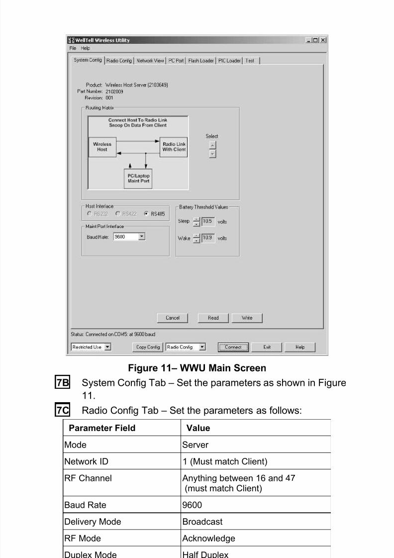
System ConfigurationStep 7 Configuring WellTell-X
In a manner similar to configuring the meters for the COM 1 port, theuser must also configure the WellTell-X radio.
To configure the WellTell-X (or the WellTell-IO) radio, the user must havethe WellTell Wireless Utility (WWU) program and a typical 9-pin to 9-pin(male DB9 to female DB9) cable. The cable connects between a laptopand the maintenance connector of the WellTell-X host.
7A The user will first need to configure the WellTell-X security.WWU supports two levels of access: Restricted Use and
Admin (lower left on the System Config tab). Restricted Use
gives the user access to the basic setup parameters that aremost often used (i.e., Network ID, RF Channel, etc.). Lesserused parameters (i.e., Encryption Key, Range Refresh, etc.)are grayed out, if Restricted Use is used. Normal setup doesnot require Admin. These lesser parameters can be accessedthrough Admin. Admin is achieved by entering the password.The factory password is 0000.
As opposed to providing an in-depth, screen-by-screen explanation ofthe WWU, the opening screen is presented to the user along withreferences to the various available tabs that contain relevant parameterson each of their corresponding screens (Figure 11).
8/13/2019 2103706 m Nad
http://slidepdf.com/reader/full/2103706-m-nad 12/20
10
Figure 11– WWU Main Screen7B System Config Tab – Set the parameters as shown in Figure
11.7C Radio Config Tab – Set the parameters as follows:
Parameter Field Value
Mode Server
Network ID 1 (Must match Client)
RF Channel Anything between 16 and 47
(must match Client)Baud Rate 9600
Delivery Mode Broadcast
RF Mode Acknowledge
Duplex Mode Half Duplex
8/13/2019 2103706 m Nad
http://slidepdf.com/reader/full/2103706-m-nad 13/20
11
7D Network View Tab – Leave at default values.
7E PC Port Tab - Set the parameters as follows:
Parameter Field Value
Port COM 1 (Communication port of thelaptop PC)
Baud Rate 9600
Data Bits 7 or 8 bits depending on user setup.
Parity Odd/Even/None depending on usersetup.
Stop Bits 1
7F Flash Loader Tab – Leave at default values.7G PIC Loader Tab – Leave at default values.
7H Test Tab – Leave at default values.
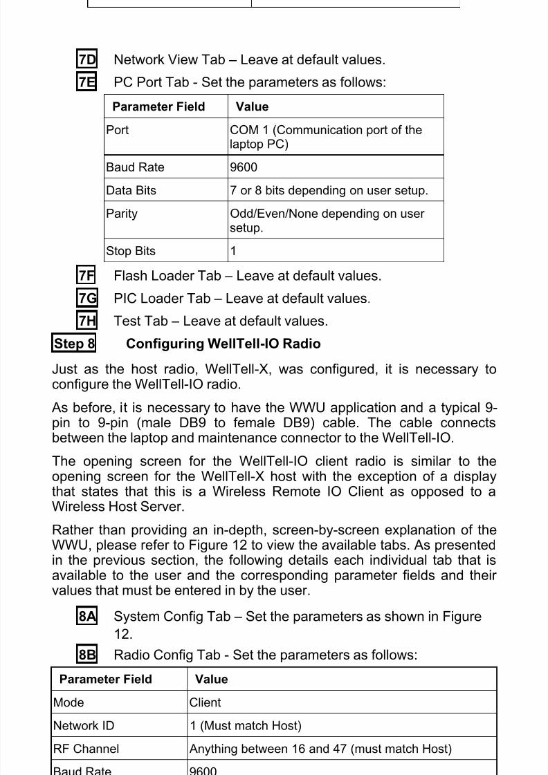
Step 8 Configuring WellTell-IO Radio
Just as the host radio, WellTell-X, was configured, it is necessary toconfigure the WellTell-IO radio.
As before, it is necessary to have the WWU application and a typical 9-pin to 9-pin (male DB9 to female DB9) cable. The cable connectsbetween the laptop and maintenance connector to the WellTell-IO.
The opening screen for the WellTell-IO client radio is similar to theopening screen for the WellTell-X host with the exception of a displaythat states that this is a Wireless Remote IO Client as opposed to aWireless Host Server.
Rather than providing an in-depth, screen-by-screen explanation of theWWU, please refer to Figure 12 to view the available tabs. As presentedin the previous section, the following details each individual tab that isavailable to the user and the corresponding parameter fields and theirvalues that must be entered in by the user.
8A System Config Tab – Set the parameters as shown in Figure12.
8B Radio Config Tab - Set the parameters as follows:
Parameter Field ValueMode Client
Network ID 1 (Must match Host)
RF Channel Anything between 16 and 47 (must match Host)
Baud Rate 9600

8/13/2019 2103706 m Nad
http://slidepdf.com/reader/full/2103706-m-nad 14/20
12
Parameter Field Value
Delivery Mode Broadcast
RF Mode Acknowledge
Duplex Mode Half Duplex8C Network View Tab – Leave at the default values.
Figure 12– WellTell IO System Configuration
8D PC Port Tab - Set the parameters as follows:Parameter Field Value
Port COM 1 (Communication port of laptop PC)
Baud Rate 9600
Data Bits 7 or 8 bits depending on user setup.

8/13/2019 2103706 m Nad
http://slidepdf.com/reader/full/2103706-m-nad 15/20
13
Parity Odd/Even/None depending on user setup.
Stop Bits 1
8E Flash Loader Tab – Leave at default values.
8F PIC Loader – Leave at default values.8G Test Tab – Leave at default values.
Step 9 Final Configuration at the Site Controller (XFC/XRC)
With the WellTell-X host and the WellTell-IO client both installed andconfigured, the system should be performing to specifications. TheWellTell-X host display will look similar to Figure 13.
Figure 13– LCD Display
The antenna symbol is on. The $ symbol is always active on theWellTell-X or host server. The – is the system heart beat and blinkscontinuously. The blink slows down whenever the radio is dead or notconnected. The F3 in the upper right of the display denotes that this is ahost server (WellTell-X). The main area of the display scrolls throughseveral parameters: baud rate, temperature, channel, etc. For moreinformation on the display, refer to the appropriate appendix.
WellTell I/O Calibration UtilityThe WellTell I/O Calibration Utility is an application that is designed tosimplify the process of calibrating a wireless I/O client locally. Theprocess is initiated when the user travels to the site of the wireless I/Oclient, connects a laptop to the client via an MMI cable and then runs theWellTell I/O Calibration Utility to perform the calibration. The calibrationinformation is then stored within the wireless I/O client (see Figure 14).

8/13/2019 2103706 m Nad
http://slidepdf.com/reader/full/2103706-m-nad 16/20
14
Figure 14– WellTell I/O Calibration UtilityStep 10 Calibrate AI Tab
As opposed to providing an in-depth, screen-by-screen explanation of
the WellTell I/O Calibration Utility, the following is going to assume thatthe user is calibrating AI 1 and using a 2 point calibration.
10A Select the AI that needs to be calibrated (1 – 4) from theSource drop-down menu. In the Calibration drop-down field,select 2 Point. Once selected, two Target values and two CalPoint buttons are made available to the user.
10B Click in the Range field, and enter a range. This can representanything (percent, volts, etc.). Click the Low Cal Point button,and enter a low calibration point from the dialog box. Click OKwhen set.
10C Click on the 100% Cal Point button, and enter the value in thedialog box. When set, click the OK button. Once all the pointsare entered, the AI is automatically calibrated.
Step 11 Calibrate AO Tab
The Calibrate AO tab enables the user to establish the calibrationparameters for the wireless I/O client’s analog outputs. The user ispresented with three fields: Eng Units, %FS and mA. The user can enterin a value within any one of these fields. The value is then automaticallysent to the wireless I/O client where a conversion is then made for theother two values. All three values are re-read from the client anddisplayed for the user. These displays are generally for informationpurposes only and will not set the client’s AO value. It should be noted,

8/13/2019 2103706 m Nad
http://slidepdf.com/reader/full/2103706-m-nad 17/20
15
however, that if the client does not wish to set the AO value with thesefigures, they can click the Send AO Value to accomplish this.
11A Calibrating the 4-20 Range Using an Ammeter (CalibrationmA). After connecting a meter, click on the Low button, and
enter the reading displayed on the meter. Click OK.11B Click on the High button, and enter the reading displayed on
the meter. Click OK. A dialog box displays informing the userthat the calibration is complete.
Entering Engineering UnitsThe user can enter units representing engineering units scaled acrossthe 4-20 mA range, but the system must have good calibration values toprovide accurate scaling. For the best results, first perform the 4-20 mAcalibration described above, and then enter the Engineering Units range.
11C Click on the Low button within the Engineering Units section,and enter the value that represents zero or the low end of therange. Click OK.
11D Click on the High button within the Engineering Units section,and enter the value that represents full scale or the high end of
the range.Step 12 Calibrate RTD
The WellTell I/O Calibration Utility allows the user to calibrate the tworesistant temperature detector (RTD) inputs. The RTD is responsible formeasuring the real-time, flowing temperature of the gas.
12A From the Source drop-down field, select the correspondingRTD that is to be calibrated. In the Bias field, place the Bias
figure in the allotted space. In the RTD Units field, set the unitsthat the RTD will be measured in: Metric or English.
LCD Display and Annunciators (see Figure 13)
Description of Standard Displays (Annunciators)
Envelope Indicates “Snoop” mode (i.e., processor is snoopingthe data stream).
Tx/Rx Indicates activity on the processor’s UART port.Antenna The Host Server (WellTell-X) annunciator is always on.
The Client (WellTell-IS or WellTell-IO) is only on whenthe Client is ‘synced’ to a Host.
Signal Strength A three section “progress bar” indicating incomingsignal strength between the Host and the Client.

8/13/2019 2103706 m Nad
http://slidepdf.com/reader/full/2103706-m-nad 18/20
16
Battery Strength A four section “progress bar” indicating incoming signalstrength between the Host and the Client.
Arrows The arrows represent up, down, left and right for a totalof four. These arrows describe the Routing Matrix ofthe WellTell Product. This Routing Matrix connects the
microprocessor (also referred to as the MaintenancePort) to either the radio or to the RS-485 device port.In Pass Through mode, the Device Port is connecteddirectly to the radio while the microprocessor can beenabled to “snoop” data from either the Device Port orthe radio. More on this topic can be found in the WWUHelp files.When the UP arrow is on, the Microprocessor cansnoop the Device Port. If the UP arrow is not on, themicroprocessor can snoop the radio. Snoop is onlyoperational in Pass Through mode (i.e., the Left andRight arrows are lit).The DOWN arrow being on informs the user that themicroprocessor is being connected in the RoutingMatrix.When the RIGHT arrow is on, this depicts that theradio is being connected in the Routing Matrix.The LEFT arrow being on depicts that the Device Port(RS-485) is being connected in the Routing Matrix.
Arrows... An example of the Routing Matrix might be having theDevice Port (RS-485) connected directly to the radio(Pass Through mode). In this configuration, the LEFTand RIGHT arrows would both be on.
F1 – F5 Annunciators F1 I.S Barrier Client indicator (WellTell-IS)F2 I/O Client indicator (WellTell-IO)F3 Host Server indictor (WellTell-X)F4 Reserved for future useF5 Test mode indicator
[ ] Right and LeftBrackets
Indicates activity on the Maintenance (processor) port.
$ Always active on the Host and inactive on the Client.M Activates whenever a cable is connected to the
Maintenance port.- The ‘dash’ or ‘underscore’ is the system heartbeat. It
blinks off and on continuously. The blinking slowswhenever the Radio is dead or not connected.
SLEEP When power drops below 10.5VDC the Host Serverwill detect the low voltage and enter a “SLEEP” mode.
Host Server and I/O and Barrier Client
b Ex: 9600 b Baud rate displayed in Numeric section.
n Ex: n 1 Network ID displayed in Numeric section.ch Ex: ch 2 Channel displayed in Numeric section.

8/13/2019 2103706 m Nad
http://slidepdf.com/reader/full/2103706-m-nad 19/20
17
b Ex: b 12.3 Battery voltage displayed in Numeric section.t Ex: t 72.1 Temperature displayed in Numeric section.
I/O and Barrier Clients 3
c Ex: c 0 Charger voltage.
L Ex: L .5 Lithium cell voltage.I/O and Barrier Clients 4
o Ex: o .0 Overload voltage.i Ex: i .0 Intrinsically safe voltage.S Ex: S 4.5 Supply voltage supervisory.
3 Not Applicable to the Host Server4 Not Applicable to the Host Server

8/13/2019 2103706 m Nad
http://slidepdf.com/reader/full/2103706-m-nad 20/20
ABB Inc.Totalflow Products7051 Industrial Blvd.Bartlesville, Oklahoma 74006
Tel: USA (800) 442-3097International 001-918-338-4880