Embed Size (px)
Citation preview
Draft Supplemental Environmental Impact Statement Keystone XL Project
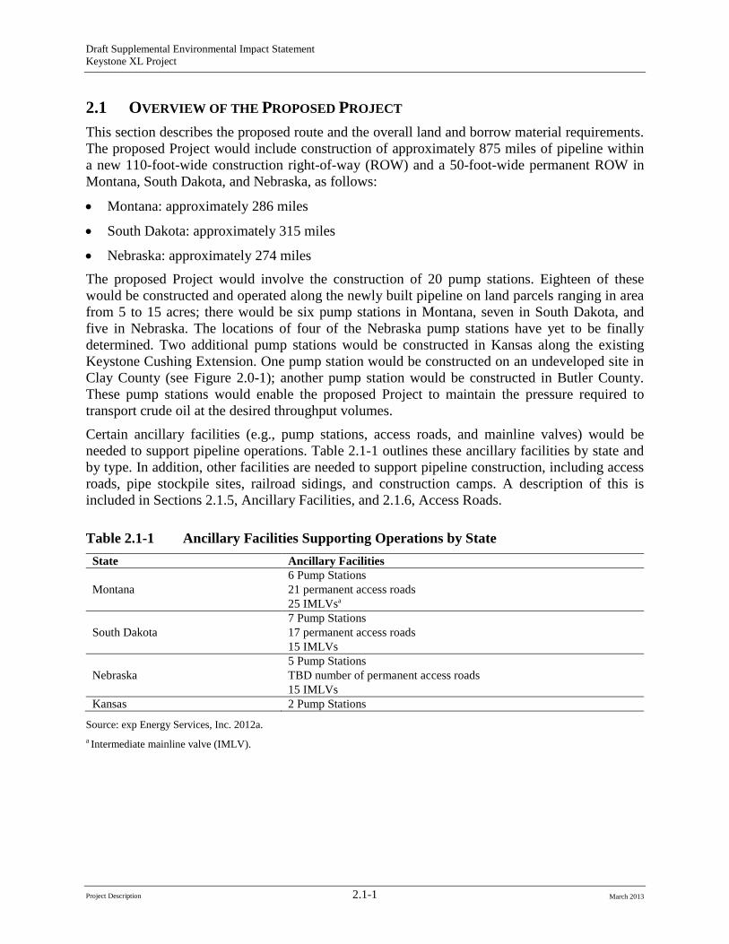
2.1 OVERVIEW OF THE PROPOSED PROJECT
This section describes the proposed route and the overall land and borrow material requirements. The proposed Project would include construction of approximately 875 miles of pipeline within a new 110-foot-wide construction right-of-way (ROW) and a 50-foot-wide permanent ROW in Montana, South Dakota, and Nebraska, as follows:
• Montana: approximately 286 miles
• South Dakota: approximately 315 miles
• Nebraska: approximately 274 miles The proposed Project would involve the construction of 20 pump stations. Eighteen of these would be constructed and operated along the newly built pipeline on land parcels ranging in area from 5 to 15 acres; there would be six pump stations in Montana, seven in South Dakota, and five in Nebraska. The locations of four of the Nebraska pump stations have yet to be finally determined. Two additional pump stations would be constructed in Kansas along the existing Keystone Cushing Extension. One pump station would be constructed on an undeveloped site in Clay County (see Figure 2.0-1); another pump station would be constructed in Butler County. These pump stations would enable the proposed Project to maintain the pressure required to transport crude oil at the desired throughput volumes.
Certain ancillary facilities (e.g., pump stations, access roads, and mainline valves) would be needed to support pipeline operations. Table 2.1-1 outlines these ancillary facilities by state and by type. In addition, other facilities are needed to support pipeline construction, including access roads, pipe stockpile sites, railroad sidings, and construction camps. A description of this is included in Sections 2.1.5, Ancillary Facilities, and 2.1.6, Access Roads.
Table 2.1-1 Ancillary Facilities Supporting Operations by State State Ancillary Facilities
Montana 6 Pump Stations 21 permanent access roads 25 IMLVsa
South Dakota 7 Pump Stations 17 permanent access roads 15 IMLVs
Nebraska 5 Pump Stations TBD number of permanent access roads 15 IMLVs
Kansas 2 Pump Stations
Source: exp Energy Services, Inc. 2012a. a Intermediate mainline valve (IMLV).
Project Description 2.1-1 March 2013
Draft Supplemental Environmental Impact Statement Keystone XL Project
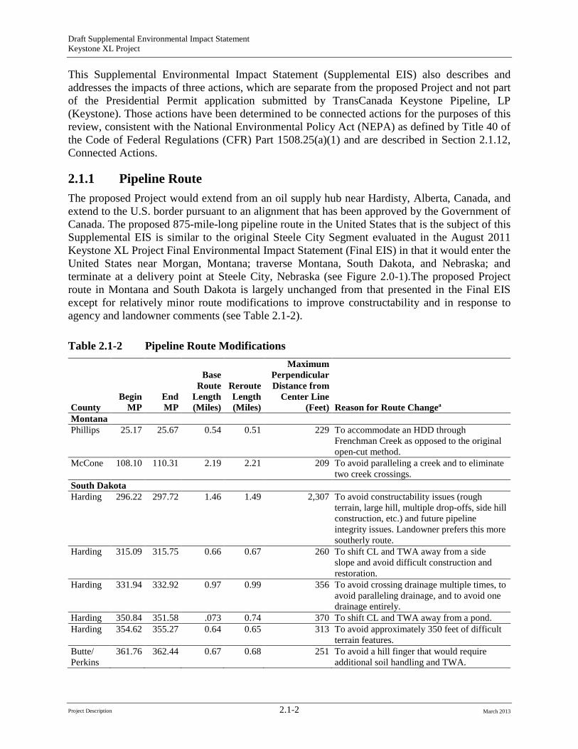
This Supplemental Environmental Impact Statement (Supplemental EIS) also describes and addresses the impacts of three actions, which are separate from the proposed Project and not part of the Presidential Permit application submitted by TransCanada Keystone Pipeline, LP (Keystone). Those actions have been determined to be connected actions for the purposes of this review, consistent with the National Environmental Policy Act (NEPA) as defined by Title 40 of the Code of Federal Regulations (CFR) Part 1508.25(a)(1) and are described in Section 2.1.12, Connected Actions.
2.1.1 Pipeline Route The proposed Project would extend from an oil supply hub near Hardisty, Alberta, Canada, and extend to the U.S. border pursuant to an alignment that has been approved by the Government of Canada. The proposed 875-mile-long pipeline route in the United States that is the subject of this Supplemental EIS is similar to the original Steele City Segment evaluated in the August 2011 Keystone XL Project Final Environmental Impact Statement (Final EIS) in that it would enter the United States near Morgan, Montana; traverse Montana, South Dakota, and Nebraska; and terminate at a delivery point at Steele City, Nebraska (see Figure 2.0-1).The proposed Project route in Montana and South Dakota is largely unchanged from that presented in the Final EIS except for relatively minor route modifications to improve constructability and in response to agency and landowner comments (see Table 2.1-2).
Table 2.1-2 Pipeline Route Modifications
County Begin
MP End
MP
Base Route
Length (Miles)
Reroute Length (Miles)
Maximum Perpendicular
Distance from Center Line
(Feet) Reason for Route Changea
Montana Phillips 25.17 25.67 0.54 0.51 229 To accommodate an HDD through
Frenchman Creek as opposed to the original open-cut method.
McCone 108.10 110.31 2.19 2.21 209 To avoid paralleling a creek and to eliminate two creek crossings.
South Dakota Harding 296.22 297.72 1.46 1.49 2,307 To avoid constructability issues (rough
terrain, large hill, multiple drop-offs, side hill construction, etc.) and future pipeline
integrity issues. Landowner prefers this more southerly route.
Harding 315.09 315.75 0.66 0.67 260 To shift CL and TWA away from a side slope and avoid difficult construction and
restoration. Harding 331.94 332.92 0.97 0.99 356 To avoid crossing drainage multiple times, to
avoid paralleling drainage, and to avoid one drainage entirely.
Harding 350.84 351.58 .073 0.74 370 To shift CL and TWA away from a pond. Harding 354.62 355.27 0.64 0.65 313 To avoid approximately 350 feet of difficult
terrain features. Butte/ Perkins
361.76 362.44 0.67 0.68 251 To avoid a hill finger that would require additional soil handling and TWA.
Project Description 2.1-2 March 2013
Draft Supplemental Environmental Impact Statement Keystone XL Project
County Begin
MP End MP
Base Route
Length (Miles)
Reroute Length (Miles)
Maximum Perpendicular Distance from
Center Line (Feet) Reason for Route Changea
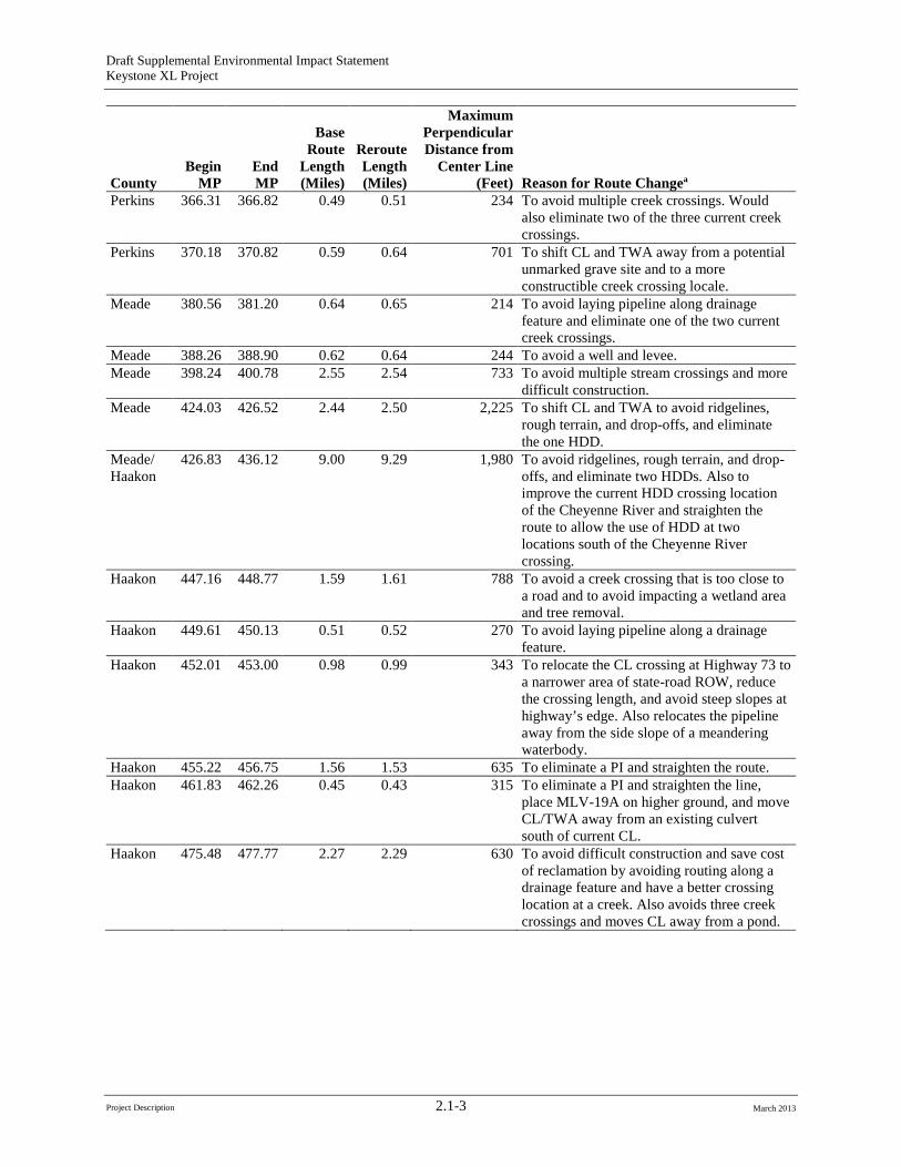
Perkins 366.31 366.82 0.49 0.51 234 To avoid multiple creek crossings. Would also eliminate two of the three current creek crossings.
Perkins 370.18 370.82 0.59 0.64 701 To shift CL and TWA away from a potential unmarked grave site and to a more constructible creek crossing locale.
Meade 380.56 381.20 0.64 0.65 214 To avoid laying pipeline along drainage feature and eliminate one of the two current creek crossings.
Meade 388.26 388.90 0.62 0.64 244 To avoid a well and levee. Meade 398.24 400.78 2.55 2.54 733 To avoid multiple stream crossings and more
difficult construction. Meade 424.03 426.52 2.44 2.50 2,225 To shift CL and TWA to avoid ridgelines,
rough terrain, and drop-offs, and eliminate the one HDD.
Meade/ 426.83 436.12 9.00 9.29 1,980 To avoid ridgelines, rough terrain, and drop-offs, and eliminate two HDDs. Also to improve the current HDD crossing location of the Cheyenne River and straighten the route to allow the use of HDD at two locations south of the Cheyenne River crossing.
Haakon
Haakon 447.16 448.77 1.59 1.61 788 To avoid a creek crossing that is too close to a road and to avoid impacting a wetland area and tree removal.
Haakon 449.61 450.13 0.51 0.52 270 To avoid laying pipeline along a drainage feature.
Haakon 452.01 453.00 0.98 0.99 343 To relocate the CL crossing at Highway 73 to a narrower area of state-road ROW, reduce the crossing length, and avoid steep slopes at highway’s edge. Also relocates the pipeline away from the side slope of a meandering waterbody.
Haakon 455.22 456.75 1.56 1.53 635 To eliminate a PI and straighten the route. Haakon 461.83 462.26 0.45 0.43 315 To eliminate a PI and straighten the line,
place MLV-19A on higher ground, and move CL/TWA away from an existing culvert south of current CL.
Haakon 475.48 477.77 2.27 2.29 630 To avoid difficult construction and save cost of reclamation by avoiding routing along a drainage feature and have a better crossing location at a creek. Also avoids three creek crossings and moves CL away from a pond.
Project Description 2.1-3 March 2013
Draft Supplemental Environmental Impact Statement Keystone XL Project
County Begin
MP End MP
Base Route
Length (Miles)
Reroute Length (Miles)
Maximum Perpendicular Distance from
Center Line (Feet) Reason for Route Changea
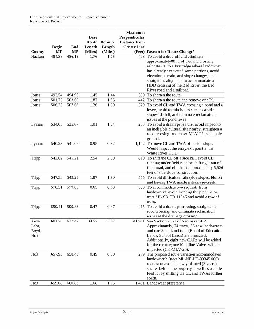
Haakon 484.38 486.13 1.76 1.75 498 To avoid a drop-off and eliminate approximately80 ft. of wetland crossing, relocate CL to a first ridge where landowner has already excavated some portions, avoid elevation, terrain, and slope changes, and straightens alignment to accommodate a HDD crossing of the Bad River, the Bad River road and a railroad.
Jones 493.54 494.98 1.45 1.44 550 To shorten the route. Jones 501.75 503.60 1.87 1.85 442 To shorten the route and remove one PI. Jones 506.33 507.63 1.26 1.30 329 To avoid CL and TWA crossing a pond and a
levee, avoid terrain issues such as a side slope/side hill, and eliminate reclamation issues at the pond/levee.
Lyman 534.03 535.07 1.01 1.04 253 To avoid a drainage feature, avoid impact to an ineligible cultural site nearby, straighten a road crossing, and move MLV-22 to suitable ground.
Lyman 540.23 541.06 0.95 0.82 1,142 To move CL and TWA off a side slope. Would impact the entry/exit point at the White River HDD.
Tripp 542.62 545.21 2.54 2.59 810 To shift the CL off a side hill, avoid CL running under field road by shifting it out of field road, and eliminate approximately 5,626 feet of side slope construction.
Tripp 547.33 549.23 1.87 1.90 555 To avoid difficult terrain (side slopes, bluffs) and having TWA inside a drainage/creek.
Tripp 578.31 579.00 0.65 0.69 550 To accommodate two requests from landowners: avoid locating the pipeline on tract ML-SD-TR-11345 and avoid a row of trees.
Tripp 599.41 599.88 0.47 0.47 415 To avoid a drainage crossing, straighten a road crossing, and eliminate reclamation issues at the drainage crossing.
Keya Paha, Boyd, Holt
601.76 637.42 34.57 35.67 41,951 See Section 2.3-1 of Nebraska SER. Approximately, 74 tracts, 36 new landowners and one State Land tract (Board of Education Lands, School Lands) are impacted. Additionally, eight new CARs will be added for the reroute; one Mainline Valve will be impacted (CK-MLV-25);
Holt 657.93 658.43 0.49 0.50 279 The proposed route variation accommodates landowner’s (tract ML-NE-HT-30345.000) request to avoid a newly planted (3 years) shelter belt on the property as well as a cattle feed lot by shifting the CL and TWAs further south.
Holt 659.08 660.83 1.68 1.75 1,481 Landowner preference
Project Description 2.1-4 March 2013
Draft Supplemental Environmental Impact Statement Keystone XL Project
County Begin
MP End MP
Base Route
Length (Miles)
Reroute Length (Miles)
Maximum Perpendicular Distance from
Center Line (Feet) Reason for Route Changea
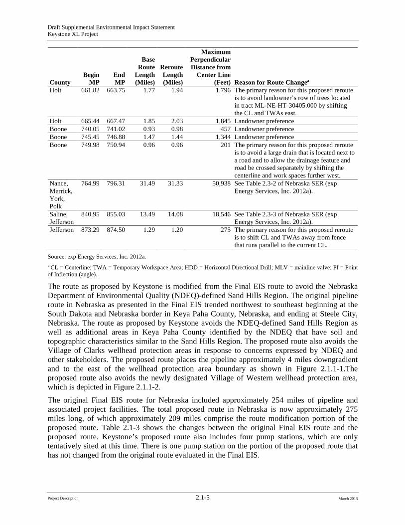
Holt 661.82 663.75 1.77 1.94 1,796 The primary reason for this proposed reroute is to avoid landowner’s row of trees located in tract ML-NE-HT-30405.000 by shifting the CL and TWAs east.
Holt 665.44 667.47 1.85 2.03 1,845 Landowner preference Boone 740.05 741.02 0.93 0.98 457 Landowner preference Boone 745.45 746.88 1.47 1.44 1,344 Landowner preference Boone 749.98 750.94 0.96 0.96 201 The primary reason for this proposed reroute
is to avoid a large drain that is located next to a road and to allow the drainage feature and road be crossed separately by shifting the centerline and work spaces further west.
Nance, Merrick, York, Polk
764.99 796.31 31.49 31.33 50,938 See Table 2.3-2 of Nebraska SER (exp Energy Services, Inc. 2012a).
Saline, Jefferson
840.95 855.03 13.49 14.08 18,546 See Table 2.3-3 of Nebraska SER (exp Energy Services, Inc. 2012a).
Jefferson 873.29 874.50 1.29 1.20 275 The primary reason for this proposed reroute is to shift CL and TWAs away from fence that runs parallel to the current CL.
Source: exp Energy Services, Inc. 2012a. a CL = Centerline; TWA = Temporary Workspace Area; HDD = Horizontal Directional Drill; MLV = mainline valve; PI = Point of Inflection (angle).
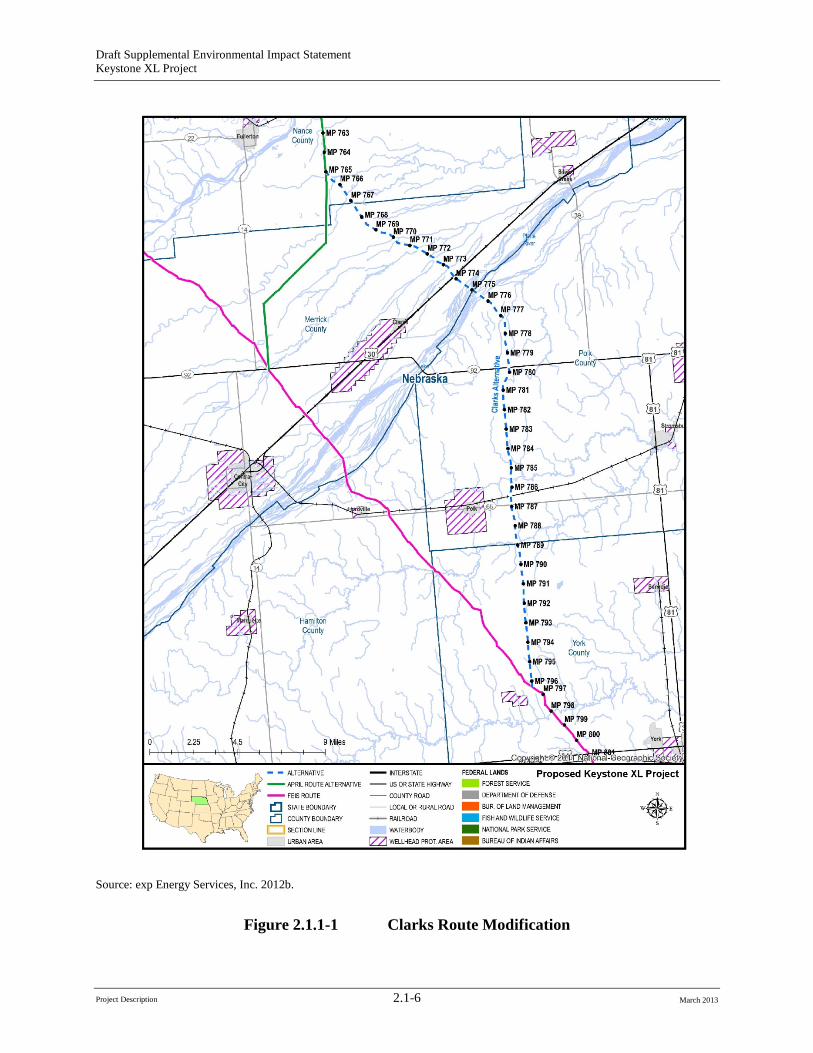
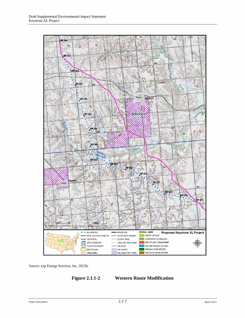
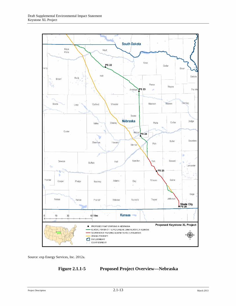
The route as proposed by Keystone is modified from the Final EIS route to avoid the Nebraska Department of Environmental Quality (NDEQ)-defined Sand Hills Region. The original pipeline route in Nebraska as presented in the Final EIS trended northwest to southeast beginning at the South Dakota and Nebraska border in Keya Paha County, Nebraska, and ending at Steele City, Nebraska. The route as proposed by Keystone avoids the NDEQ-defined Sand Hills Region as well as additional areas in Keya Paha County identified by the NDEQ that have soil and topographic characteristics similar to the Sand Hills Region. The proposed route also avoids the Village of Clarks wellhead protection areas in response to concerns expressed by NDEQ and other stakeholders. The proposed route places the pipeline approximately 4 miles downgradient and to the east of the wellhead protection area boundary as shown in Figure 2.1.1-1.The proposed route also avoids the newly designated Village of Western wellhead protection area, which is depicted in Figure 2.1.1-2.
The original Final EIS route for Nebraska included approximately 254 miles of pipeline and associated project facilities. The total proposed route in Nebraska is now approximately 275 miles long, of which approximately 209 miles comprise the route modification portion of the proposed route. Table 2.1-3 shows the changes between the original Final EIS route and the proposed route. Keystone’s proposed route also includes four pump stations, which are only tentatively sited at this time. There is one pump station on the portion of the proposed route that has not changed from the original route evaluated in the Final EIS.
Project Description 2.1-5 March 2013
Draft Supplemental Environmental Impact Statement Keystone XL Project
Source: exp Energy Services, Inc. 2012b.
Figure 2.1.1-1 Clarks Route Modification
Project Description 2.1-6 March 2013
Draft Supplemental Environmental Impact Statement Keystone XL Project
Source: exp Energy Services, Inc. 2012b.
Figure 2.1.1-2 Western Route Modification
Project Description 2.1-7 March 2013
Draft Supplemental Environmental Impact Statement Keystone XL Project
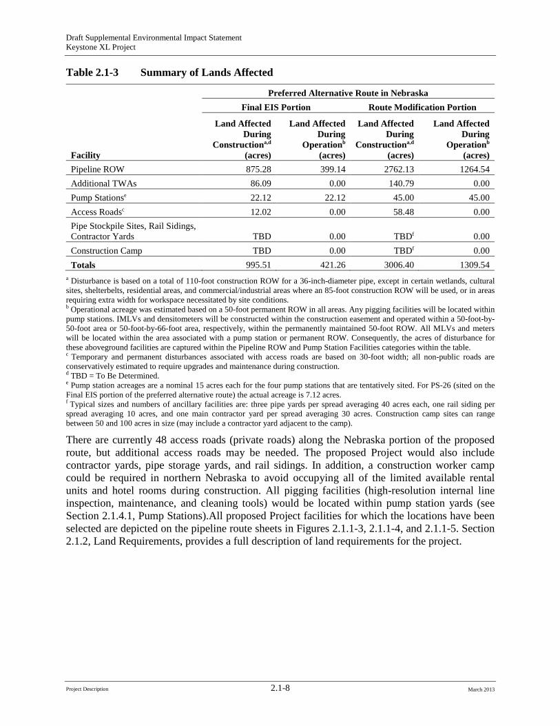
Table 2.1-3 Summary of Lands Affected
Facility
Preferred Alternative Route in Nebraska Final EIS Portion Route Modification Portion
Land Affected During
Constructiona,d
(acres)
Land Affected During
Operationb
(acres)
Land Affected During
Constructiona,d
(acres)
Land Affected During
Operationb
(acres) Pipeline ROW 875.28 399.14 2762.13 1264.54 Additional TWAs 86.09 0.00 140.79 0.00 Pump Stationse 22.12 22.12 45.00 45.00 Access Roadsc 12.02 0.00 58.48 0.00 Pipe Stockpile Sites, Rail Sidings, Contractor Yards TBD 0.00 TBDf 0.00 Construction Camp TBD 0.00 TBDf 0.00 Totals 995.51 421.26 3006.40 1309.54
a Disturbance is based on a total of 110-foot construction ROW for a 36-inch-diameter pipe, except in certain wetlands, cultural sites, shelterbelts, residential areas, and commercial/industrial areas where an 85-foot construction ROW will be used, or in areas requiring extra width for workspace necessitated by site conditions.b Operational acreage was estimated based on a 50-foot permanent ROW in all areas. Any pigging facilities will be located within pump stations. IMLVs and densitometers will be constructed within the construction easement and operated within a 50-foot-by50-foot area or 50-foot-by-66-foot area, respectively, within the permanently maintained 50-foot ROW. All MLVs and meters will be located within the area associated with a pump station or permanent ROW. Consequently, the acres of disturbance for these aboveground facilities are captured within the Pipeline ROW and Pump Station Facilities categories within the table. c Temporary and permanent disturbances associated with access roads are based on 30-foot width; all non-public roads are conservatively estimated to require upgrades and maintenance during construction.d TBD = To Be Determined. e Pump station acreages are a nominal 15 acres each for the four pump stations that are tentatively sited. For PS-26 (sited on the Final EIS portion of the preferred alternative route) the actual acreage is 7.12 acres.f Typical sizes and numbers of ancillary facilities are: three pipe yards per spread averaging 40 acres each, one rail siding per spread averaging 10 acres, and one main contractor yard per spread averaging 30 acres. Construction camp sites can range between 50 and 100 acres in size (may include a contractor yard adjacent to the camp).
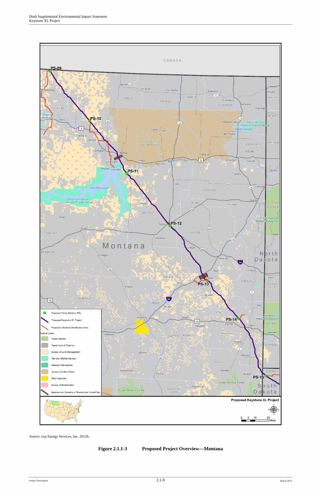
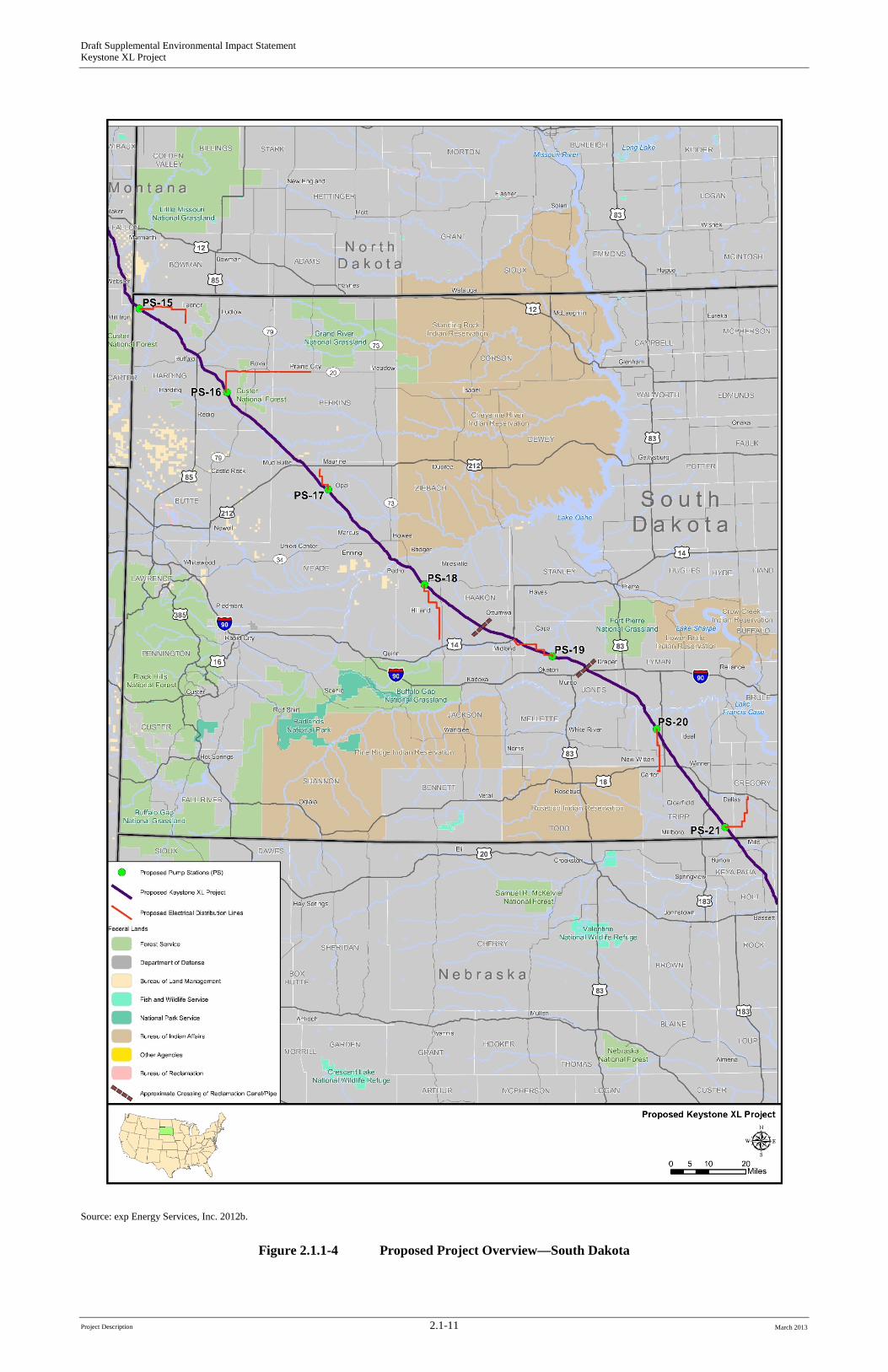
There are currently 48 access roads (private roads) along the Nebraska portion of the proposed route, but additional access roads may be needed. The proposed Project would also include contractor yards, pipe storage yards, and rail sidings. In addition, a construction worker camp could be required in northern Nebraska to avoid occupying all of the limited available rental units and hotel rooms during construction. All pigging facilities (high-resolution internal line inspection, maintenance, and cleaning tools) would be located within pump station yards (see Section 2.1.4.1, Pump Stations).All proposed Project facilities for which the locations have been selected are depicted on the pipeline route sheets in Figures 2.1.1-3, 2.1.1-4, and 2.1.1-5. Section 2.1.2, Land Requirements, provides a full description of land requirements for the project.
Project Description 2.1-8 March 2013
Draft Supplemental Environmental Impact Statement Keystone XL Project
Source: exp Energy Services, Inc. 2012b.
Figure 2.1.1-3 Proposed Project Overview—Montana
Project Description 2.1-9 March 2013

Draft Supplemental Environmental Impact Statement Keystone XL Project
-Page Intentionally Left Blank-
Project Description 2.1-10 March 2013
Draft Supplemental Environmental Impact Statement Keystone XL Project
Source: exp Energy Services, Inc. 2012b.
Figure 2.1.1-4 Proposed Project Overview—South Dakota
Project Description 2.1-11 March 2013

Draft Supplemental Environmental Impact Statement Keystone XL Project
-Page Intentionally Left Blank-
Project Description 2.1-12 March 2013
Draft Supplemental Environmental Impact Statement Keystone XL Project
Source: exp Energy Services, Inc. 2012a.
Figure 2.1.1-5 Proposed Project Overview—Nebraska
Project Description 2.1-13 March 2013
Draft Supplemental Environmental Impact Statement Keystone XL Project
2.1.2 Land Requirements Approximately 15,493 acres of land would be disturbed during construction. The permanent ROW and aboveground facilities make up a total of 5,583.7 acres. Table 2.1-3 shows the areas in acres affected by construction and operation of the proposed Project. The following are proposed Project activities that would require the use of land:
• Pipeline ROW;
• Additional temporary workspace areas (TWAs);
• Pipe stockpile sites, rail sidings, and contractor yards;
• Construction camps;
• Pump stations and delivery facilities; and
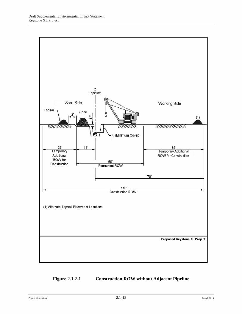
• Access roads. Construction of the proposed Project would require a 110-foot-wide construction ROW. In certain sensitive areas, which may include wetlands, cultural sites, shelterbelts, residential areas, or commercial/industrial areas, the construction ROW would be reduced to 85 feet to minimize impacts to these sensitive areas. Figure 2.1.2-1 illustrates typical construction areas along the ROW. After construction, the ROW would be restored consistent with applicable federal and state regulations and permits, the easement agreements negotiated between Keystone and individual landowners or land managers, and the construction methods and environmental protection procedures described in the Keystone Construction, Mitigation, and Reclamation Plan (CMRP) (presented in Appendix G and described in Section 2.1.7, Pipeline System Design and Construction Procedures). Those measures would be incorporated into the proposed Project to reduce the potential impacts of construction. After restoration, the approximately 9,909 acres of temporary ROW would be returned to the property owners for their use.
The permanent ROW would be approximately 5,584 acres, which includes approximately 214 acres for pump stations, valves, and other aboveground facilities. Access to the permanent ROW would be maintained for the life of the proposed Project to support surface and aerial inspections and any repairs or maintenance as necessary.
2.1.3 Borrow Material Requirements Borrow (or fill) material would be required for temporary sites (such as storage sites, contractor yards, temporary access roads, and access pads at ROW road crossings) to stabilize the land for permanent facilities (including pump stations, valve sites, and permanent access roads), and for padding the bottom of the pipeline trench in some areas. All gravel and other borrow material would be obtained from existing, previously permitted commercial sources located as close to the pipe or contractor yards as possible.
Project Description 2.1-14 March 2013
Draft Supplemental Environmental Impact Statement Keystone XL Project
Figure 2.1.2-1 Construction ROW without Adjacent Pipeline
Project Description 2.1-15 March 2013
Draft Supplemental Environmental Impact Statement Keystone XL Project
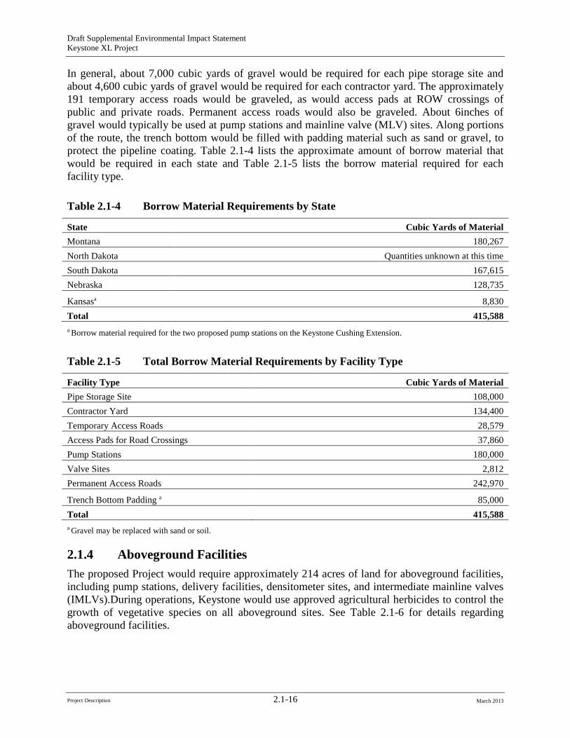
In general, about 7,000 cubic yards of gravel would be required for each pipe storage site and about 4,600 cubic yards of gravel would be required for each contractor yard. The approximately 191 temporary access roads would be graveled, as would access pads at ROW crossings of public and private roads. Permanent access roads would also be graveled. About 6inches of gravel would typically be used at pump stations and mainline valve (MLV) sites. Along portions of the route, the trench bottom would be filled with padding material such as sand or gravel, to protect the pipeline coating. Table 2.1-4 lists the approximate amount of borrow material that would be required in each state and Table 2.1-5 lists the borrow material required for each facility type.
Table 2.1-4 Borrow Material Requirements by State
State Cubic Yards of Material Montana 180,267 North Dakota Quantities unknown at this time South Dakota 167,615 Nebraska 128,735
Kansasa 8,830 Total 415,588 a Borrow material required for the two proposed pump stations on the Keystone Cushing Extension.
Table 2.1-5 Total Borrow Material Requirements by Facility Type
Facility Type Cubic Yards of Material Pipe Storage Site 108,000 Contractor Yard 134,400 Temporary Access Roads 28,579 Access Pads for Road Crossings 37,860 Pump Stations 180,000 Valve Sites 2,812 Permanent Access Roads 242,970
Trench Bottom Padding a 85,000 Total 415,588 a Gravel may be replaced with sand or soil.
2.1.4 Aboveground Facilities The proposed Project would require approximately 214 acres of land for aboveground facilities, including pump stations, delivery facilities, densitometer sites, and intermediate mainline valves (IMLVs).During operations, Keystone would use approved agricultural herbicides to control the growth of vegetative species on all aboveground sites. See Table 2.1-6 for details regarding aboveground facilities.
Project Description 2.1-16 March 2013
Draft Supplemental Environmental Impact Statement Keystone XL Project
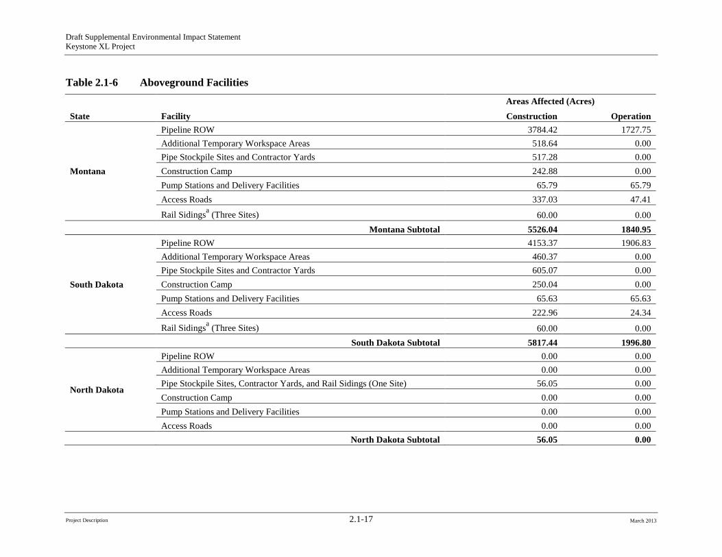
Table 2.1-6 Aboveground Facilities
State Facility Areas Affected (Acres) Construction Operation
Montana
Pipeline ROW 3784.42 1727.75 Additional Temporary Workspace Areas 518.64 0.00 Pipe Stockpile Sites and Contractor Yards 517.28 0.00 Construction Camp 242.88 0.00 Pump Stations and Delivery Facilities 65.79 65.79 Access Roads 337.03 47.41
Rail Sidingsa (Three Sites) 60.00 0.00 Montana Subtotal 5526.04 1840.95
South Dakota
Pipeline ROW 4153.37 1906.83 Additional Temporary Workspace Areas 460.37 0.00 Pipe Stockpile Sites and Contractor Yards 605.07 0.00 Construction Camp 250.04 0.00 Pump Stations and Delivery Facilities 65.63 65.63 Access Roads 222.96 24.34
Rail Sidingsa (Three Sites) 60.00 0.00 South Dakota Subtotal 5817.44 1996.80
North Dakota
Pipeline ROW 0.00 0.00 Additional Temporary Workspace Areas 0.00 0.00 Pipe Stockpile Sites, Contractor Yards, and Rail Sidings (One Site) 56.05 0.00 Construction Camp 0.00 0.00 Pump Stations and Delivery Facilities 0.00 0.00 Access Roads 0.00 0.00
North Dakota Subtotal 56.05 0.00
Project Description 2.1-17 March 2013
Draft Supplemental Environmental Impact Statement Keystone XL Project
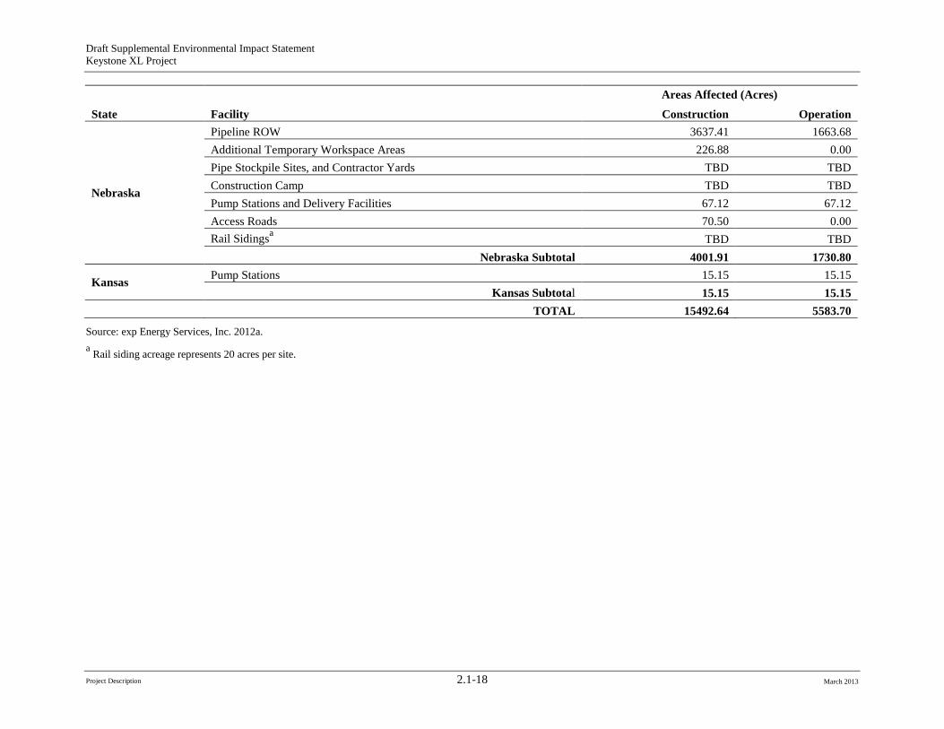
State Facility Areas Affected (Acres) Construction Operation
Nebraska
Pipeline ROW 3637.41 1663.68 Additional Temporary Workspace Areas 226.88 0.00 Pipe Stockpile Sites, and Contractor Yards TBD TBD Construction Camp TBD TBD Pump Stations and Delivery Facilities 67.12 67.12 Access Roads 70.50 0.00 Rail Sidingsa TBD TBD
Nebraska Subtotal 4001.91 1730.80
Kansas Pump Stations 15.15 15.15 Kansas Subtotal 15.15 15.15
TOTAL 15492.64 5583.70
Source: exp Energy Services, Inc. 2012a. a Rail siding acreage represents 20 acres per site.
Project Description 2.1-18 March 2013
Project Description 2.1-19
Draft Supplemental Environmental Impact Statement Keystone XL Project
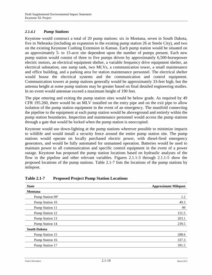
2.1.4.1 Pump Stations Keystone would construct a total of 20 pump stations: six in Montana, seven in South Dakota, five in Nebraska (including an expansion to the existing pump station 26 at Steele City), and two on the existing Keystone Cushing Extension in Kansas. Each pump station would be situated on an approximately 5- to 15-acre site dependent upon the number of pumps present. Each new pump station would consist of three to five pumps driven by approximately 6,500-horsepower electric motors, an electrical equipment shelter, a variable frequency drive equipment shelter, an electrical substation, one sump tank, two MLVs, a communication tower, a small maintenance and office building, and a parking area for station maintenance personnel. The electrical shelter would house the electrical systems and the communication and control equipment. Communication towers at pump stations generally would be approximately 33-feet high, but the antenna height at some pump stations may be greater based on final detailed engineering studies. In no event would antennae exceed a maximum height of 190 feet.
The pipe entering and exiting the pump station sites would be below grade. As required by 49 CFR 195.260, there would be an MLV installed on the entry pipe and on the exit pipe to allow isolation of the pump station equipment in the event of an emergency. The manifold connecting the pipeline to the equipment at each pump station would be aboveground and entirely within the pump station boundaries. Inspection and maintenance personnel would access the pump stations through a gate that would be locked when the pump station is unoccupied.
Keystone would use down-lighting at the pump stations wherever possible to minimize impacts to wildlife and would install a security fence around the entire pump station site. The pump stations would operate on locally purchased electric power, with diesel-fired emergency generators, and would be fully automated for unmanned operation. Batteries would be used to maintain power to all communication and specific control equipment in the event of a power outage. Keystone has proposed the pump station locations based on hydraulic analyses of the flow in the pipeline and other relevant variables. Figures 2.1.1-3 through 2.1.1-5 show the proposed locations of the pump stations. Table 2.1-7 lists the locations of the pump stations by milepost.
Table 2.1-7 Proposed Project Pump Station Locations
State Approximate Milepost Montana
Pump Station 09a 1.2 Pump Station 10 49.3 Pump Station 11 99 Pump Station 12 151.5 Pump Station 13 203.1 Pump Station 14 239.5
South Dakota Pump Station 15 288.6 Pump Station 16 337.3 Pump Station 17 391.5
March 2013
Draft Supplemental Environmental Impact Statement Keystone XL Project
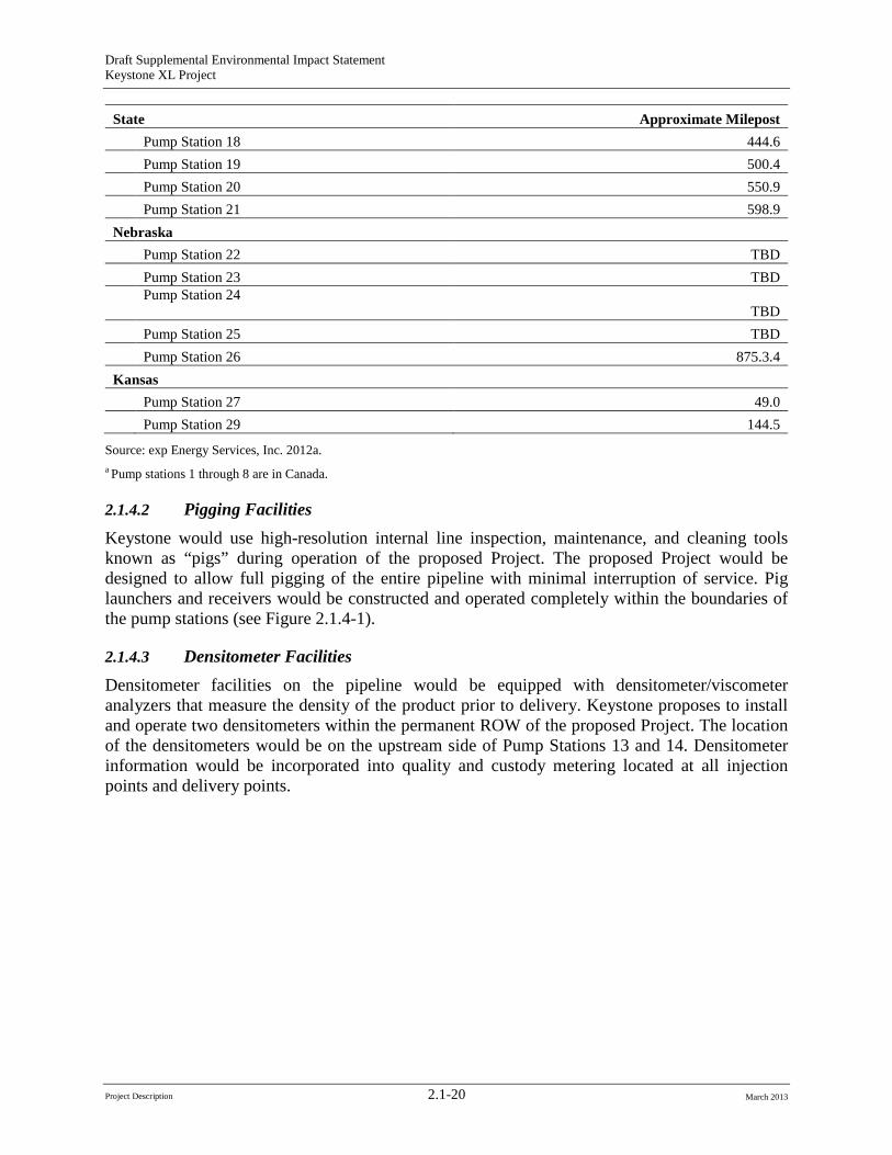
State Approximate Milepost Pump Station 18 444.6 Pump Station 19 500.4 Pump Station 20 550.9 Pump Station 21 598.9
Nebraska Pump Station 22 TBD Pump Station 23 TBD Pump Station 24
TBD Pump Station 25 TBD Pump Station 26 875.3.4
Kansas Pump Station 27 49.0
1Pump Station 29 44.5
Source: exp Energy Services, Inc. 2012a. a Pump stations 1 through 8 are in Canada.
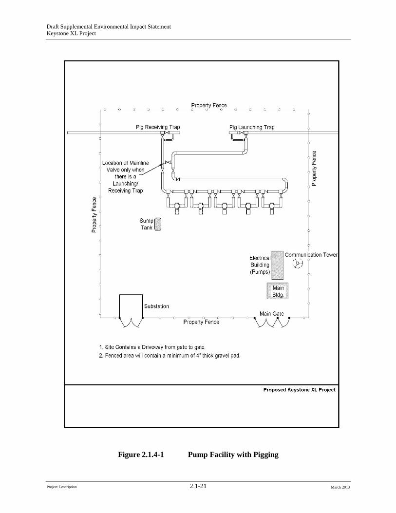
2.1.4.2 Pigging Facilities Keystone would use high-resolution internal line inspection, maintenance, and cleaning tools known as “pigs” during operation of the proposed Project. The proposed Project would be designed to allow full pigging of the entire pipeline with minimal interruption of service. Pig launchers and receivers would be constructed and operated completely within the boundaries of the pump stations (see Figure 2.1.4-1).
2.1.4.3 Densitometer Facilities Densitometer facilities on the pipeline would be equipped with densitometer/viscometer analyzers that measure the density of the product prior to delivery. Keystone proposes to install and operate two densitometers within the permanent ROW of the proposed Project. The location of the densitometers would be on the upstream side of Pump Stations 13 and 14. Densitometer information would be incorporated into quality and custody metering located at all injection points and delivery points.
Project Description 2.1-20 March 2013
Draft Supplemental Environmental Impact Statement Keystone XL Project
Figure 2.1.4-1 Pump Facility with Pigging
Project Description 2.1-21 March 2013
Draft Supplemental Environmental Impact Statement Keystone XL Project
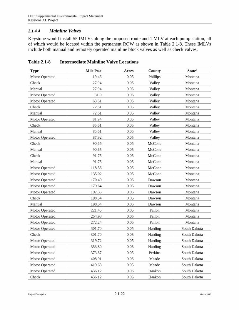
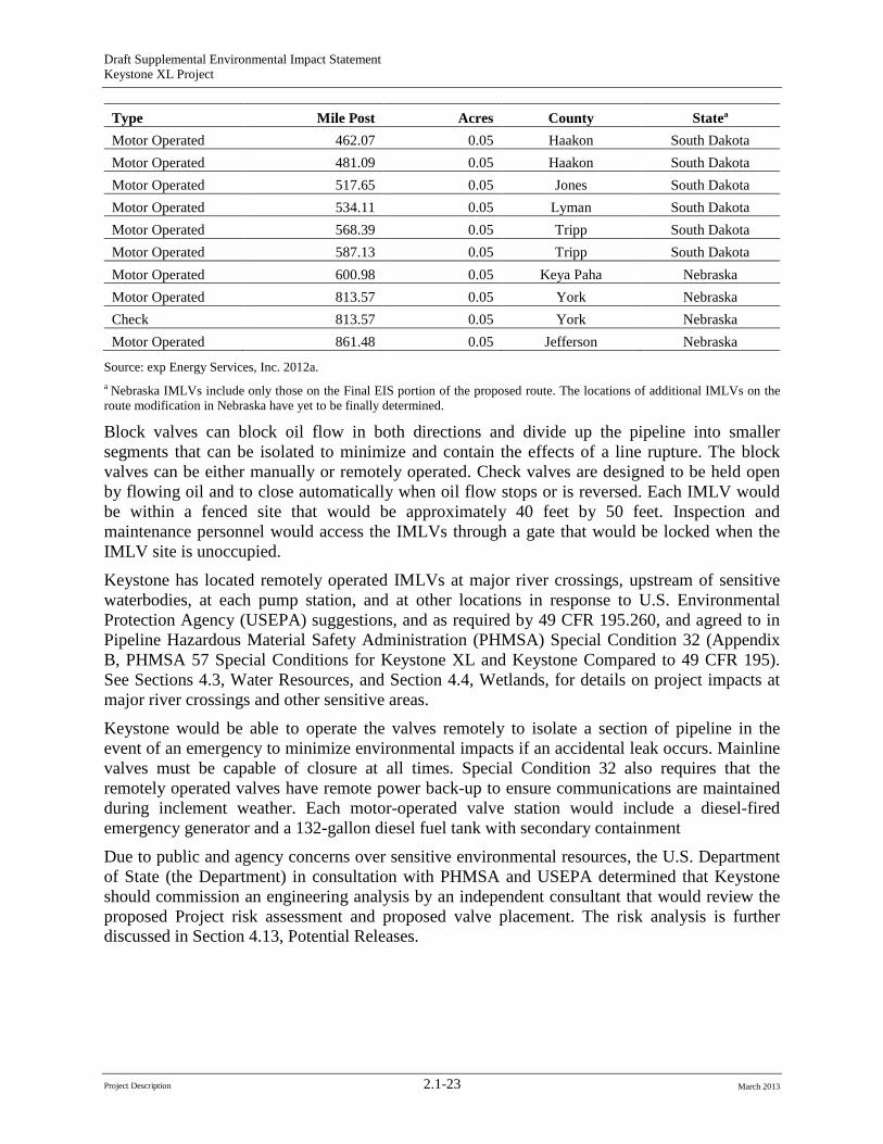
2.1.4.4 Mainline Valves Keystone would install 55 IMLVs along the proposed route and 1 MLV at each pump station, all of which would be located within the permanent ROW as shown in Table 2.1-8. These IMLVs include both manual and remotely operated mainline block valves as well as check valves.
Table 2.1-8 Intermediate Mainline Valve Locations
Type Mile Post Acres County Statea
Motor Operated 19.46 0.05 Phillips Montana Check 27.94 0.05 Valley Montana Manual 27.94 0.05 Valley Montana Motor Operated 31.9 0.05 Valley Montana Motor Operated 63.61 0.05 Valley Montana Check 72.61 0.05 Valley Montana Manual 72.61 0.05 Valley Montana Motor Operated 81.94 0.05 Valley Montana Check 85.61 0.05 Valley Montana Manual 85.61 0.05 Valley Montana Motor Operated 87.92 0.05 Valley Montana Check 90.65 0.05 McCone Montana Manual 90.65 0.05 McCone Montana Check 91.75 0.05 McCone Montana Manual 91.75 0.05 McCone Montana Motor Operated 118.36 0.05 McCone Montana Motor Operated 135.02 0.05 McCone Montana Motor Operated 170.49 0.05 Dawson Montana Motor Operated 179.64 0.05 Dawson Montana Motor Operated 197.35 0.05 Dawson Montana Check 198.34 0.05 Dawson Montana Manual 198.34 0.05 Dawson Montana Motor Operated 221.45 0.05 Fallon Montana Motor Operated 254.93 0.05 Fallon Montana Motor Operated 272.24 0.05 Fallon Montana Motor Operated 301.70 0.05 Harding South Dakota Check 301.70 0.05 Harding South Dakota Motor Operated 319.72 0.05 Harding South Dakota Motor Operated 353.89 0.05 Harding South Dakota Motor Operated 373.87 0.05 Perkins South Dakota Motor Operated 408.91 0.05 Meade South Dakota Motor Operated 419.68 0.05 Meade South Dakota Motor Operated 436.12 0.05 Haakon South Dakota Check 436.12 0.05 Haakon South Dakota
Project Description 2.1-22 March 2013
Draft Supplemental Environmental Impact Statement Keystone XL Project
Type Mile Post Acres County Statea
Motor Operated 462.07 0.05 Haakon South Dakota Motor Operated 481.09 0.05 Haakon South Dakota Motor Operated 517.65 0.05 Jones South Dakota Motor Operated 534.11 0.05 Lyman South Dakota Motor Operated 568.39 0.05 Tripp South Dakota Motor Operated 587.13 0.05 Tripp South Dakota Motor Operated 600.98 0.05 Keya Paha Nebraska Motor Operated 813.57 0.05 York Nebraska Check 813.57 0.05 York Nebraska Motor Operated 861.48 0.05 Jefferson Nebraska
Source: exp Energy Services, Inc. 2012a. a Nebraska IMLVs include only those on the Final EIS portion of the proposed route. The locations of additional IMLVs on the route modification in Nebraska have yet to be finally determined.
Block valves can block oil flow in both directions and divide up the pipeline into smaller segments that can be isolated to minimize and contain the effects of a line rupture. The block valves can be either manually or remotely operated. Check valves are designed to be held open by flowing oil and to close automatically when oil flow stops or is reversed. Each IMLV would be within a fenced site that would be approximately 40 feet by 50 feet. Inspection and maintenance personnel would access the IMLVs through a gate that would be locked when the IMLV site is unoccupied.
Keystone has located remotely operated IMLVs at major river crossings, upstream of sensitive waterbodies, at each pump station, and at other locations in response to U.S. Environmental Protection Agency (USEPA) suggestions, and as required by 49 CFR 195.260, and agreed to in Pipeline Hazardous Material Safety Administration (PHMSA) Special Condition 32 (Appendix B, PHMSA 57 Special Conditions for Keystone XL and Keystone Compared to 49 CFR 195). See Sections 4.3, Water Resources, and Section 4.4, Wetlands, for details on project impacts at major river crossings and other sensitive areas.
Keystone would be able to operate the valves remotely to isolate a section of pipeline in the event of an emergency to minimize environmental impacts if an accidental leak occurs. Mainline valves must be capable of closure at all times. Special Condition 32 also requires that the remotely operated valves have remote power back-up to ensure communications are maintained during inclement weather. Each motor-operated valve station would include a diesel-fired emergency generator and a 132-gallon diesel fuel tank with secondary containment
Due to public and agency concerns over sensitive environmental resources, the U.S. Department of State (the Department) in consultation with PHMSA and USEPA determined that Keystone should commission an engineering analysis by an independent consultant that would review the proposed Project risk assessment and proposed valve placement. The risk analysis is further discussed in Section 4.13, Potential Releases.
Project Description 2.1-23 March 2013
Draft Supplemental Environmental Impact Statement Keystone XL Project
2.1.5 Ancillary Facilities
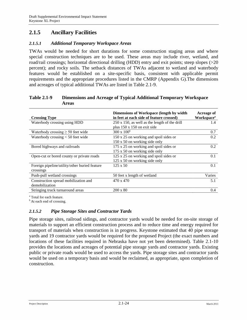
2.1.5.1 Additional Temporary Workspace Areas TWAs would be needed for short durations for some construction staging areas and where special construction techniques are to be used. These areas may include river, wetland, and road/rail crossings; horizontal directional drilling (HDD) entry and exit points; steep slopes (>20 percent); and rocky soils. The setback distances of TWAs adjacent to wetland and waterbody features would be established on a site-specific basis, consistent with applicable permit requirements and the appropriate procedures listed in the CMRP (Appendix G).The dimensions and acreages of typical additional TWAs are listed in Table 2.1-9.
Table 2.1-9 Dimensions and Acreage of Typical Additional Temporary Workspace Areas
Crossing Type Dimensions of Workspace (length by width in feet at each side of feature crossed)
Acreage of Workspacea
Waterbody crossing using HDD 250 x 150, as well as the length of the drill plus 150 x 150 on exit side
1.4
Waterbody crossing ≥ 50 feet wide 300 x 100b 0.7 Waterbody crossing < 50 feet wide 150 x 25 on working and spoil sides or
150 x 50 on working side only 0.2
Bored highways and railroads 175 x 25 on working and spoil sides or 175 x 50 on working side only
0.2
Open-cut or bored county or private roads 125 x 25 on working and spoil sides or 125 x 50 on working side only
0.1
Foreign pipeline/utility/other buried feature crossings
125 x 50 0.1
Push-pull wetland crossings 50 feet x length of wetland Varies Construction spread mobilization and demobilization
470 x 470 5.1
Stringing truck turnaround areas 200 x 80 0.4 a Total for each feature. b At each end of crossing.
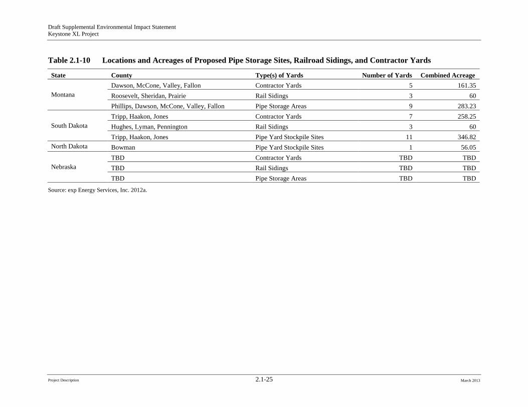
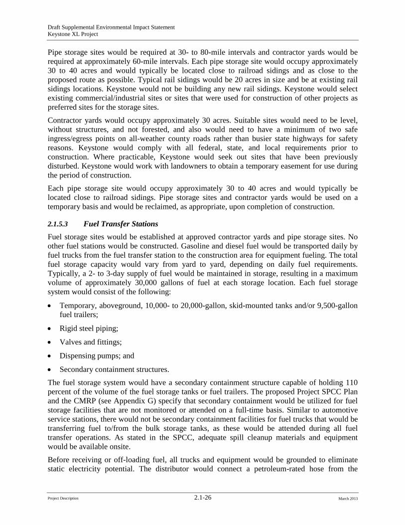
2.1.5.2 Pipe Storage Sites and Contractor Yards Pipe storage sites, railroad sidings, and contractor yards would be needed for on-site storage of materials to support an efficient construction process and to reduce time and energy required for transport of materials when construction is in progress. Keystone estimated that 40 pipe storage yards and 19 contractor yards would be required for the proposed Project (the exact numbers and locations of these facilities required in Nebraska have not yet been determined). Table 2.1-10 provides the locations and acreages of potential pipe storage yards and contractor yards. Existing public or private roads would be used to access the yards. Pipe storage sites and contractor yards would be used on a temporary basis and would be reclaimed, as appropriate, upon completion of construction.
Project Description 2.1-24 March 2013
Draft Supplemental Environmental Impact Statement Keystone XL Project
Table 2.1-10 Locations and Acreages of Proposed Pipe Storage Sites, Railroad Sidings, and Contractor Yards
State County Type(s) of Yards Number of Yards Combined Acreage
Montana Dawson, McCone, Valley, Fallon Contractor Yards 5 161.35 Roosevelt, Sheridan, Prairie Rail Sidings 3 60 Phillips, Dawson, McCone, Valley, Fallon Pipe Storage Areas 9 283.23
South Dakota Tripp, Haakon, Jones Contractor Yards 7 258.25 Hughes, Lyman, Pennington Rail Sidings 3 60 Tripp, Haakon, Jones Pipe Yard Stockpile Sites 11 346.82
North Dakota Bowman Pipe Yard Stockpile Sites 1 56.05
Nebraska TBD Contractor Yards TBD TBD TBD Rail Sidings TBD TBD TBD Pipe Storage Areas TBD TBD
Source: exp Energy Services, Inc. 2012a.
Project Description 2.1-25 March 2013
Draft Supplemental Environmental Impact Statement Keystone XL Project
Pipe storage sites would be required at 30- to 80-mile intervals and contractor yards would be required at approximately 60-mile intervals. Each pipe storage site would occupy approximately 30 to 40 acres and would typically be located close to railroad sidings and as close to the proposed route as possible. Typical rail sidings would be 20 acres in size and be at existing rail sidings locations. Keystone would not be building any new rail sidings. Keystone would select existing commercial/industrial sites or sites that were used for construction of other projects as preferred sites for the storage sites.
Contractor yards would occupy approximately 30 acres. Suitable sites would need to be level, without structures, and not forested, and also would need to have a minimum of two safe ingress/egress points on all-weather county roads rather than busier state highways for safety reasons. Keystone would comply with all federal, state, and local requirements prior to construction. Where practicable, Keystone would seek out sites that have been previously disturbed. Keystone would work with landowners to obtain a temporary easement for use during the period of construction.
Each pipe storage site would occupy approximately 30 to 40 acres and would typically be located close to railroad sidings. Pipe storage sites and contractor yards would be used on a temporary basis and would be reclaimed, as appropriate, upon completion of construction.
2.1.5.3 Fuel Transfer Stations Fuel storage sites would be established at approved contractor yards and pipe storage sites. No other fuel stations would be constructed. Gasoline and diesel fuel would be transported daily by fuel trucks from the fuel transfer station to the construction area for equipment fueling. The total fuel storage capacity would vary from yard to yard, depending on daily fuel requirements. Typically, a 2- to 3-day supply of fuel would be maintained in storage, resulting in a maximum volume of approximately 30,000 gallons of fuel at each storage location. Each fuel storage system would consist of the following:
• Temporary, aboveground, 10,000- to 20,000-gallon, skid-mounted tanks and/or 9,500-gallon fuel trailers;
• Rigid steel piping;
• Valves and fittings;
• Dispensing pumps; and
• Secondary containment structures.
The fuel storage system would have a secondary containment structure capable of holding 110 percent of the volume of the fuel storage tanks or fuel trailers. The proposed Project SPCC Plan and the CMRP (see Appendix G) specify that secondary containment would be utilized for fuel storage facilities that are not monitored or attended on a full-time basis. Similar to automotive service stations, there would not be secondary containment facilities for fuel trucks that would be transferring fuel to/from the bulk storage tanks, as these would be attended during all fuel transfer operations. As stated in the SPCC, adequate spill cleanup materials and equipment would be available onsite.
Before receiving or off-loading fuel, all trucks and equipment would be grounded to eliminate static electricity potential. The distributor would connect a petroleum-rated hose from the
Project Description 2.1-26 March 2013
Draft Supplemental Environmental Impact Statement Keystone XL Project
delivery tanker to the fill line at the storage facility. The connection between the delivery tanker and the fill line would consist of a cam-loc connection followed by a block valve, rigid steel piping, tank block valve(s), and check valve(s) just upstream of the connection to the tank. Off-loading of fuel would be accomplished by a transfer pump powered by the delivery vehicles. The transfer pump would be a dispensing pump with petroleum-rated hoses with automatic shut-off nozzles. There would be no use of Stage II vapor recovery nozzles for fuel transfer on the proposed Project. The Stage II requirements contained in the 1990 Clean Air Act Amendments pertain only to ozone nonattainment areas. The proposed Project area is not an ozone nonattainment area.1
The fuel transfer pump would have an emergency shut-off at the pump and a secondary emergency shut-off at least 100 feet away.
Vehicle maintenance would be performed at the contractor yards or at existing vehicle maintenance and repair shops. As specified in Keystone’s CMRP Section 3.0, Spill Prevention and Containment, during vehicle maintenance at the contractor yards, mechanics will place absorbent materials or drip pans under the equipment to prevent petroleum, oil, or other lubricants from reaching the ground. In the event that small quantities of soil become contaminated, contractor personnel will recover and place the contaminated soil in 55-gallon drums. This material will ultimately be disposed in accordance with state and federal regulations. All waste from maintenance activities would be disposed of in accordance with all applicable regulations and permits.
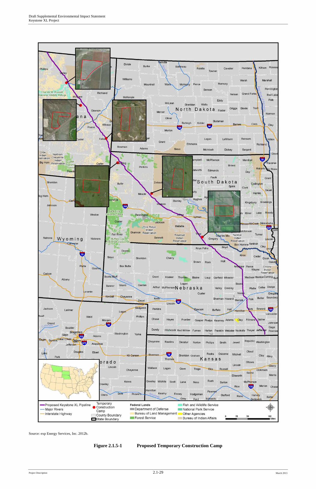
2.1.5.4 Construction Camps Some areas within Montana, South Dakota, and Nebraska do not have sufficient temporary housing in the vicinity of the proposed route for all construction personnel working in those areas. Temporary work camps would be constructed to meet the housing needs of the construction workforce in these remote locations. As shown in Figure 2.1.5-1, a total of eight temporary construction camps would be established It is currently anticipated that four construction camps would be needed in Montana (McCone, Valley [2], and Fallon counties), three camps would be required in South Dakota (Tripp, Harding, and Meade counties), and one camp would be required in Nebraska (Holt county) (see Appendix H, 2012 Biological Assessment).
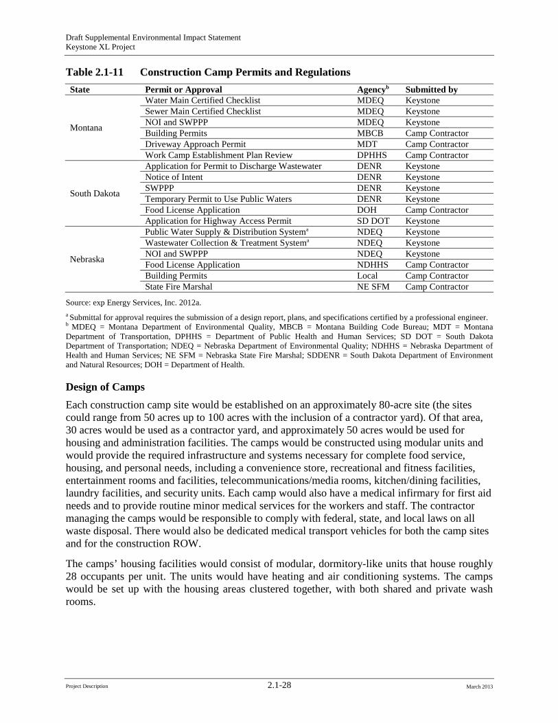
The number and size of camps would be determined based on the time available to complete construction and to meet Keystone’s commercial commitments. All construction camps would be permitted, constructed, and operated consistent with applicable county, state, and federal regulations. The relevant regulations that would have to be complied with and the permits required for the construction camps are presented in Table 2.1-11.
1 See http://www.epa.gov/ttn/atw/gasdist/technica.pdf.
Project Description 2.1-27 March 2013
Draft Supplemental Environmental Impact Statement Keystone XL Project
Table 2.1-11 Construction Camp Permits and Regulations State Permit or Approval Agencyb Submitted by
Montana
Water Main Certified Checklist MDEQ Keystone Sewer Main Certified Checklist MDEQ Keystone NOI and SWPPP Building Permits
MDEQ MBCB
Keystone Camp Contractor
Driveway Approach Permit MDT Camp Contractor Work Camp Establishment Plan Review DPHHS Camp Contractor
South Dakota
Application for Permit to Discharge Wastewater DENR Keystone Notice of Intent DENR Keystone SWPPP DENR Keystone Temporary Permit to Use Public Waters DENR Keystone Food License Application DOH Camp Contractor Application for Highway Access Permit SD DOT Keystone
Nebraska
Public Water Supply & Distribution Systema NDEQ Keystone Wastewater Collection & Treatment Systema NDEQ Keystone NOI and SWPPP NDEQ Keystone Food License Application NDHHS Camp Contractor Building Permits Local Camp Contractor State Fire Marshal NE SFM Camp Contractor
Source: exp Energy Services, Inc. 2012a. a Submittal for approval requires the submission of a design report, plans, and specifications certified by a professional engineer. b MDEQ = Montana Department of Environmental Quality, MBCB = Montana Building Code Bureau; MDT = Montana Department of Transportation, DPHHS = Department of Public Health and Human Services; SD DOT = South Dakota Department of Transportation; NDEQ = Nebraska Department of Environmental Quality; NDHHS = Nebraska Department of Health and Human Services; NE SFM = Nebraska State Fire Marshal; SDDENR = South Dakota Department of Environment and Natural Resources; DOH = Department of Health.
Design of Camps Each construction camp site would be established on an approximately 80-acre site (the sites could range from 50 acres up to 100 acres with the inclusion of a contractor yard). Of that area, 30 acres would be used as a contractor yard, and approximately 50 acres would be used for housing and administration facilities. The camps would be constructed using modular units and would provide the required infrastructure and systems necessary for complete food service, housing, and personal needs, including a convenience store, recreational and fitness facilities, entertainment rooms and facilities, telecommunications/media rooms, kitchen/dining facilities, laundry facilities, and security units. Each camp would also have a medical infirmary for first aid needs and to provide routine minor medical services for the workers and staff. The contractor managing the camps would be responsible to comply with federal, state, and local laws on all waste disposal. There would also be dedicated medical transport vehicles for both the camp sites and for the construction ROW.
The camps’ housing facilities would consist of modular, dormitory-like units that house roughly 28 occupants per unit. The units would have heating and air conditioning systems. The camps would be set up with the housing areas clustered together, with both shared and private wash rooms.
Project Description 2.1-28 March 2013
Draft Supplemental Environmental Impact Statement Keystone XL Project
Source: exp Energy Services, Inc. 2012b.
Figure 2.1.5-1 Proposed Temporary Construction Camp
Project Description 2.1-29 March 2013

Draft Supplemental Environmental Impact Statement Keystone XL Project
-Page Intentionally Left Blank-
Project Description 2.1-30 March 2013
Draft Supplemental Environmental Impact Statement Keystone XL Project
Each camp would contain 600 beds and 300 recreational vehicle spots. Keystone conservatively intends to permit each camp for 1,000 residents to allow for those instances where there may be more than 1 person in a recreational vehicle. Potable water would be provided by drilling a well where feasible and allowed. If Keystone cannot get a permit from the state to install a water well, water would be hauled to the camp from the nearest permitted municipal supply, as discussed below.
If an adequate supply cannot be obtained from a well, water would be obtained from municipal sources or trucked to each camp. Siting of the camps near existing municipal water sources would be a key consideration in locations currently experiencing water restrictions or drought conditions. A self-contained wastewater treatment facility would be included in each camp except where it is practicable to use a licensed and permitted publically owned treatment works. Wastewater treated on site would undergo primary, secondary, and tertiary treatment consisting of solids removal, bioreactor treatment, membrane filtration, and ultraviolet exposure. Final effluent discharge would be consistent with all applicable regulatory requirements. If a publically owned treatment works is used, Keystone would either pipe or truck wastewater to the treatment facility.
Electricity for the camps would either be generated on-site through diesel-fired generators, or would be provided by local utilities from an interconnection to their distribution system. Keystone would contract with a camp supplier that would provide security 24 hours per day, 7 days per week at each camp. Keystone would work with the supplier to ensure that as many local employees are hired as possible to staff the camps.
Use of Camps The camps are planned to service the needs of the proposed Project workforce. As a result, the dormitories do not include facilities for families. Most of the workers would be transported to and from the ROW each day by buses. In addition, there would be individual crews and workers that, due to the nature of their work, would be transported to and from job sites by utility trucks or by welding rigs. There would also be support workers such as mechanics, parts and supply staff, and supervisory personnel that would drive to the ROW in separate vehicles.
Based on the current construction schedule, the camps would operate in standby mode during the winter (from December through March or April). Each camp would have sufficient staff to operate and secure the camp and associated systems during that time period.
Decommissioning of Camps Decommissioning would be accomplished in two stages. First, all infrastructure systems would be removed and either hauled away for reuse, recycled, or disposed of in accordance with regulatory requirements. Each site would then be restored and reclaimed in accordance with permit requirements and the applicable procedures described in Keystone’s CMRP (Appendix G).
Project Description 2.1-31 March 2013

Draft Supplemental Environmental Impact Statement Keystone XL Project
2.1.6 Access Roads
2.1.6.1 Development of Access Roads Existing public and private roads would be used to provide access to most of the construction ROW. Paved roads would not likely require improvement or maintenance prior to or during construction. However, the road infrastructure would be inspected prior to construction to ensure that the roads, bridges, and cattle guards would be able to withstand oversized vehicle use during construction. Gravel roads and dirt roads may require maintenance during the construction period due to high use. Road improvements such as blading and filling would generally be restricted to the existing road footprint; however, some roads may require widening in some areas.
To the extent Keystone is required to conduct maintenance of any county roads, it would be done pursuant to an agreement with the applicable county. In the event that oversized or overweight loads would be needed to transport construction materials to the proposed Project work sites, Keystone would submit required permit applications to the appropriate state regulatory agencies.
Approximately 191 temporary access roads would be needed to provide adequate access to the construction sites. Private roads and any new temporary access roads would be used and maintained only with permission of the landowner or the appropriate land management agency. There are currently 48 access roads (private roads) along the Nebraska portion of the proposed route, but additional access roads may be needed. Keystone would also construct short, permanent, access roads from public roads to the pump stations, delivery facilities, and IMLVs. Approximately 21 permanent access roads would be needed in Montana and 17 permanent access roads in South Dakota. The number in Nebraska is still to be determined.
The final locations of new, permanent, access roads would be determined prior to construction. At a minimum, construction of new permanent access roads would require completion of cultural resources and biological surveys and consultations and approvals of the appropriate State Historic Preservation Office and U.S. Fish and Wildlife Service office. Keystone would comply with all federal, state, and local requirements prior to construction. Maintenance of newly created access roads would be the responsibility of Keystone as described below.
The acreages of access roads are included in the listing of lands affected in Table 2.1-6. Access road temporary and permanent disturbance estimates are based on the 30-foot roadway width required to accommodate oversized vehicles. In developing the acreages of disturbance, all non-public roads were conservatively estimated to require upgrades and maintenance during construction.
2.1.6.2 Roadway Maintenance, Repair, and Safety Keystone would work with state and local road officials, the pipeline construction contractor, and a third-party road consultant to identify routes to be used for moving materials and equipment between storage and work yards to the pipeline, valve, and pump station construction sites. When these routes are mutually agreed upon, the road consultant would document the existing conditions of roads, including a video record. When construction is completed, the same parties would review the road conditions and Keystone would restore the roads to their preconstruction condition or better. Keystone would pay for this restoration.
Project Description 2.1-32 March 2013
Draft Supplemental Environmental Impact Statement Keystone XL Project
Keystone would also perform a preliminary evaluation to determine the design-rated capacity of bridges anticipated to be used during construction and would inspect all bridges it intends to use prior to construction and confirm that the capacity of the bridges is adequate for the anticipated weights. An alternate route would be used where the bridges are not adequate to handle the maximum weight. Keystone would also inspect cattle guard crossings prior to their use. If they are determined to be inadequate to handle anticipated construction traffic, Keystone may place mats on crossings, establish an alternate crossing, enhance existing structures, or install new infrastructure with the landowner’s approval, dependent upon specific conditions. Keystone would pay for all such actions.
During construction, Keystone and the pipeline contractor would maintain roads used for construction in a condition that is safe for both the public and workforce. Local road officials would be actively engaged in the routine assessment of road conditions.
Keystone would follow all federal, state, and local safety plans and signage as set forth in the various applicable Manuals of Uniform Traffic Control issued by federal, state, or local agencies for streets and highways along the proposed route. This would include compliance with all state and local permits pertaining to road and crossing infrastructure usage.
Keystone would require that each construction contractor submit a road-use plan prior to mobilization, coordinate with the appropriate state and county representatives to develop a mutually acceptable plan, and obtain all necessary road use permits. The road-use plans would identify potential scenarios that may occur during construction based on surrounding land use, known recreational activities, and seasonal influences (such as farming), and would establish measures to reduce or avoid effects to local communities. Keystone would also have inspection personnel monitor road-use activities to ensure that the construction contractors comply with the road-use plans and stipulations of the road.
Some counties in Montana stipulate that a private individual conducting maintenance of a county road becomes liable for the safety of traffic on the road. Where this is required, Keystone has stated it would be done pursuant to an agreement with the applicable county, and such agreements would address potential liability, including appropriate indemnity and insurance provisions. Keystone has the necessary insurance coverage to address such potential liability.
2.1.7 Pipeline System Design and Construction Procedures Public concern has been expressed about the safety of the proposed Project, the use of industry standards in the design of the proposed Project, and the inspection and monitoring procedures that would be conducted. Prior to construction in Nebraska, Keystone would select, subject to NDEQ approval, and pay for, a public liaison officer to facilitate the exchange of information between Keystone and landowners, local communities, and residents. The purpose of the public liaison officer would be to respond to questions or concerns and to resolve promptly any complaints or problems that may develop as a result of construction. The public liaison officer would report to NDEQ or as otherwise directed by NDEQ. Additionally, South Dakota and Montana have laid out specific requirements for this role under their regulatory processes (South Dakota Public Utilities Commission Permit and the Montana Major Facility Siting Act Certificate, respectively).
The U.S. Department of Transportation’s (USDOT) PHMSA is responsible for protecting the American public and the environment by ensuring the safe and secure movement of hazardous
Project Description 2.1-33 March 2013
Draft Supplemental Environmental Impact Statement Keystone XL Project
materials to industry and consumers by all transportation modes, including the nation’s pipelines. Through PHMSA, USDOT develops and enforces regulations for the safe, reliable, and environmentally sound operation of the nation’s 2.3-million-mile pipeline transportation system and the nearly 1 million daily shipments of hazardous materials by land, sea, and air. Within PHMSA, the Office of Pipeline Safety has the safety authority for the nation’s natural gas and hazardous liquid pipelines. The proposed Project is included in the latter category.
Keystone would be required to construct, operate, maintain, inspect, and monitor the proposed Project consistent with the PHMSA requirements presented in 49 CFR 195 (Transportation of Hazardous Liquids by Pipeline), as well as relevant industry standards, and applicable state standards. These regulations specify pipeline material and qualification standards, minimum design requirements, and required measures to protect the pipeline from internal, external, and atmospheric corrosion. The regulations are designed to prevent crude oil pipeline accidents and to ensure adequate protection for the public.
Pipelines that carry gasoline, diesel fuel, crude oil, or other hazardous liquids must implement additional safety measures if they cross a particularly sensitive area such as the source for a municipal drinking water supply. Keystone would comply with a set of 57 Special Conditions developed by PHMSA for the proposed Project (see Appendix B, PHMSA 57 Special Conditions). The Department, in consultation with PHMSA, has determined that incorporation of those conditions would result in a proposed Project that would have an improved degree of safety relative to typically constructed domestic oil pipelines and a degree of safety along the entire length of the pipeline system similar to that which is required in high consequence areas (HCAs) as defined in 49 CFR 195.450. These Special Conditions cover four general categories of project activities:
• Material requirements;
• Construction requirements;
• Operations and maintenance; and
• Reporting, records retention, and senior-level certification requirements. The regulations are designed to help prevent crude oil pipeline accidents and to ensure adequate protection for the public. Section 2.1.7.1, Pipeline Design, presents the major pipeline design considerations of the proposed Project. Nearly all petroleum pipelines in the United States are buried, and Keystone has also proposed to bury the proposed Project pipeline. In addition, the Special Conditions provide more stringent requirements for many of these design factors. In comparison to an aboveground pipeline, burying a pipeline reduces the potential for pipeline damage due to vandalism, sabotage, and the effects of other outside forces, such as vehicle collisions.
Keystone prepared a draft CMRP that is included in Appendix G. That plan describes the construction methods and environmental protection measures that Keystone committed to in order to reduce the potential construction impacts of the proposed Project. The CMRP includes specific techniques or mitigation measures to address sensitive areas such as highly erodible soils, shallow groundwater, and other conditions. If the proposed Project is issued a Presidential Permit, the CMRP would be updated after the Record of Decision is issued to reflect any additional conditions included in the Record of Decision and in other permits issued to Keystone, and to reflect regional construction considerations.
Project Description 2.1-34 March 2013
Draft Supplemental Environmental Impact Statement Keystone XL Project
Prior to pipeline construction, Keystone would prepare a Spill Prevention, Control, and Countermeasure Plan to avoid or minimize the potential for harmful spills and leaks during construction. A draft version of the Spill Prevention, Control, and Countermeasure Plan submitted by Keystone is included in Appendix I.
In addition, Keystone would submit a Pipeline Spill Response Plan (PSRP) to PHMSA prior to the initiation of proposed Project operations in accordance with the requirements of 49 CFR 194. The PSRP would describe how spills would be responded to in the event of a leak from the proposed Project resulting from any cause as well as the maximum spill scenario and the procedures that would be in place to deal with the maximum spill. As required by 49 CFR 195.40, Keystone would also prepare and follow a manual of written procedures for conducting normal operations and maintenance activities and handling abnormal operations and emergencies that would include Keystone’s Emergency Response Plan (ERP). The PSRP and the ERP are addressed in Section 4.13, Potential Releases. The remainder of this section provides information on the following topics:
• Pipeline Design (Section 2.1.7.1); and
• Pipeline Construction Procedures (Section 2.1.7.2). Special Pipeline Construction Procedures are provided in Section 2.1.8; Section 2.1.9 provides information on Waterbody Crossings.
2.1.7.1 Pipeline Design All pipe used for the proposed Project would be required to be in compliance with the pipe design requirements of 49 CFR 195, Subpart C (Design Requirements) and 49 CFR 195.106 (Internal Design Pressure), and the PHMSA 57 Special Conditions. The pipeline would be constructed of high-strength, X70 steel pipe that would be mill-inspected by an authorized owner’s inspector and mill-tested to American Petroleum Institute (API) 5L (API 5L2
2The API 5L test standard is used to determine the fracture ductility of metal line pipe. Specimens are cut from sections of pipe, soaked at a prescribed temperature, and tested within 10 seconds.
) specification requirements. If shipped by rail, the shipment would be made in accordance with the API Recommended Practice 5 Ll specification latest edition; if shipped by barge or marine transport, the shipment would be in accordance with API Recommended Practice 5LW. Additional details on pipeline safety and project design are presented in the following sections and in Section 4.13, Potential Releases.
Project Description 2.1-35 March 2013
Draft Supplemental Environmental Impact Statement Keystone XL Project
The design parameters for steel pipe would be determined in accordance with the following equation (see 49 CFR 195.106—Internal Design Pressure):
P=(2*S*t/D)*E*F
where:
P=Internal design pressure in psi (kPa3) gage
S=Yield strength in pounds per square inch (kPa)
D=Nominal outside diameter of the pipe in inches
t=Nominal wall thickness of the pipe in inches
F=Design factor
E=Seam joint factor
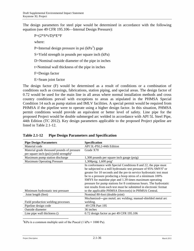
The design factor (F) would be determined as a result of conditions or a combination of conditions such as crossings, fabrications, station piping, and special areas. The design factor of 0.72 would be used for the main line in all areas where normal installation methods and cross country conditions prevail with exceptions to areas as stipulated in the PHMSA Special Condition 14 such as pump station and IMLV facilities. A special permit would be required from PHMSA if the pipeline were to operate using a higher design factor. In this situation, PHMSA permit conditions would provide an equivalent or better level of safety. Line pipe for the proposed Project would be double submerged arc welded in accordance with API 5L Steel Pipe, 44th Edition (TC 2012). Key design parameters applicable to the proposed Project pipeline are listed in Table 2.1-12.
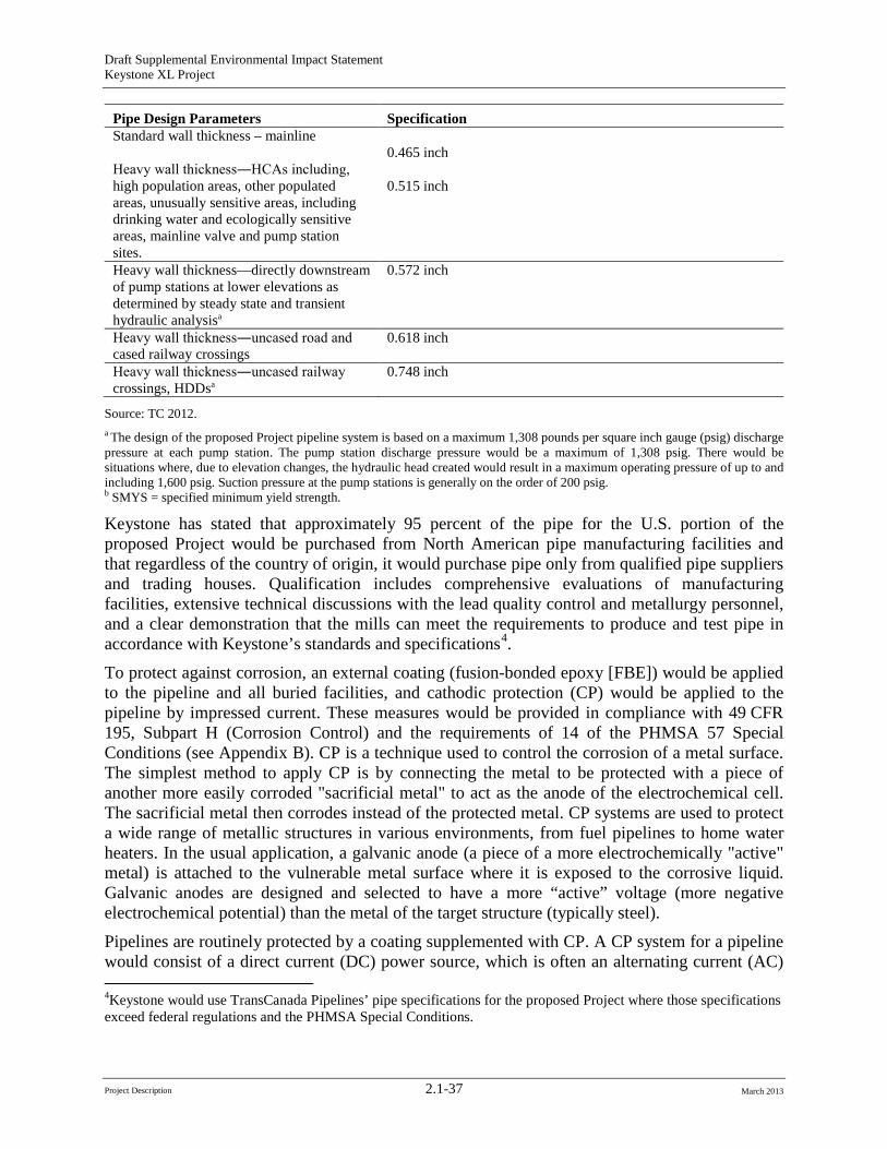
Table 2.1-12 Pipe Design Parameters and Specification
Pipe Design Parameters Specification Material code API 5L-PSL2-44th Edition Material grade thousand pounds of pressure per square inch (psi) (yield strength)a
Grade X70
Maximum pump station discharge 1,308 pounds per square inch gauge (psig) Maximum Operating Pressure 1,308psig; 1,600 psiga
Minimum hydrostatic test pressure
In conformance with Special Conditions 8 and 22, the pipe must be subjected to a mill hydrostatic test pressure of 95% SMYSb or greater for 10 seconds and the pre-in service hydrostatic test must be to a pressure producing a hoop stress of a minimum 100% SMYS for mainline pipe and 1.39 times maximum operating pressure for pump stations for 8 continuous hours. The hydrostatic test results from each test must be submitted in electronic format to the applicable PHMSA Director(s) in PHMSA Central.
Joint length (feet) Nominal 80-foot (double-joint)
Field production welding processes Mechanized―gas metal; arc welding; manual-shielded metal arc welding.
Pipeline design code 49 CFR Part 195 Outside diameter 36 inches Line pipe wall thickness () 0.72 design factor as per 49 CFR 195.106
3KPa is a common multiple unit of the Pascal (1 kPa ≡ 1000 Pa).
Project Description 2.1-36 March 2013
Draft Supplemental Environmental Impact Statement Keystone XL Project
Pipe Design Parameters Specification Standard wall thickness – mainline
0.465 inch Heavy wall thickness―HCAs including, high population areas, other populated areas, unusually sensitive areas, including drinking water and ecologically sensitive areas, mainline valve and pump station sites.
0.515 inch
Heavy wall thickness—directly downstream of pump stations at lower elevations as determined by steady state and transient hydraulic analysisa
0.572 inch
Heavy wall thickness―uncased road and cased railway crossings
0.618 inch
Heavy wall thickness―uncased railway crossings, HDDsa
0.748 inch
Source: TC 2012. a The design of the proposed Project pipeline system is based on a maximum 1,308 pounds per square inch gauge (psig) discharge pressure at each pump station. The pump station discharge pressure would be a maximum of 1,308 psig. There would be situations where, due to elevation changes, the hydraulic head created would result in a maximum operating pressure of up to and including 1,600 psig. Suction pressure at the pump stations is generally on the order of 200 psig.b SMYS = specified minimum yield strength.
Keystone has stated that approximately 95 percent of the pipe for the U.S. portion of the proposed Project would be purchased from North American pipe manufacturing facilities and that regardless of the country of origin, it would purchase pipe only from qualified pipe suppliers and trading houses. Qualification includes comprehensive evaluations of manufacturing facilities, extensive technical discussions with the lead quality control and metallurgy personnel, and a clear demonstration that the mills can meet the requirements to produce and test pipe in accordance with Keystone’s standards and specifications4
4Keystone would use TransCanada Pipelines’ pipe specifications for the proposed Project where those specifications exceed federal regulations and the PHMSA Special Conditions.
.
To protect against corrosion, an external coating (fusion-bonded epoxy [FBE]) would be applied to the pipeline and all buried facilities, and cathodic protection (CP) would be applied to the pipeline by impressed current. These measures would be provided in compliance with 49 CFR 195, Subpart H (Corrosion Control) and the requirements of 14 of the PHMSA 57 Special Conditions (see Appendix B). CP is a technique used to control the corrosion of a metal surface. The simplest method to apply CP is by connecting the metal to be protected with a piece of another more easily corroded "sacrificial metal" to act as the anode of the electrochemical cell. The sacrificial metal then corrodes instead of the protected metal. CP systems are used to protect a wide range of metallic structures in various environments, from fuel pipelines to home water heaters. In the usual application, a galvanic anode (a piece of a more electrochemically "active" metal) is attached to the vulnerable metal surface where it is exposed to the corrosive liquid. Galvanic anodes are designed and selected to have a more “active” voltage (more negative electrochemical potential) than the metal of the target structure (typically steel).
Pipelines are routinely protected by a coating supplemented with CP. A CP system for a pipeline would consist of a direct current (DC) power source, which is often an alternating current (AC)
Project Description 2.1-37 March 2013
Draft Supplemental Environmental Impact Statement Keystone XL Project
powered rectifier and an anode, or array of anodes, buried in the ground (the anode groundbed). A rectifier is an electrical device that converts AC, which periodically reverses direction, to DC, which flows in only one direction. The process is known as rectification. Rectifiers are often found serving as components of DC power supplies and high-voltage DC power transmission systems. The primary impressed current CP systems would be rectifiers coupled to semi-deep vertical anode beds at each pump station, as well as rectifiers coupled to deep-well anode beds at selected IMLV sites. During operation, the CP system would be monitored and remediation performed to prolong the anode bed and systems. The semi-deep anode beds would be 12-inchdiameter vertical holes spaced 15 feet apart with a bottom hole depth of approximately 45 feet. The deep-well anode bed would be a single 12-inch-diameter vertical hole with a bottom hole depth of approximately 300 feet.
2.1.7.2 Pipeline Construction Procedures Keystone is a limited partnership, organized under the laws of the State of Delaware. Keystone is the entity that would be responsible for construction of the pipeline if approved. To construct, operate, and maintain the proposed Project, Keystone would need the rights to easements along the entire proposed route. Keystone is responsible for acquiring easement rights from landowners along the route in each state. Easement agreements would list the conditions that both the landowner and Keystone agree to, including financial compensation to the landowners in return for granting easements. Compensation would also be made for loss of use during construction, crop loss, loss of non-renewable or other resources, and restoration of any unavoidable damage to personal property during construction. The Department expects Keystone to negotiate fairly, honestly, and respectfully with landowners when they negotiate an easement. However, those negotiations and final agreements are private business concerns between the landowners and Keystone.
If Keystone obtains all necessary permits and approvals and an easement negotiation cannot be completed in a manner suitable to both parties, Keystone may attempt to use state eminent domain laws to obtain easements needed for pipeline construction, maintenance, and operation. State laws dictate under what circumstances eminent domain may be used and define the eminent domain process within the state. The level of compensation would be determined according to applicable state law. State or local trespass and access laws are applicable along the entire route and therefore along each easement negotiated by Keystone and the landowner or obtained by Keystone through the eminent domain process. The Department has no legal authority over negotiating easement agreements and has no legal status to enforce the conditions of an easement agreement. A landowner who considers Keystone to be out of compliance with an easement agreement would need to discuss the matter with Keystone or local law enforcement officials, or initiate legal consultation.
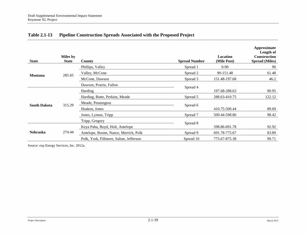
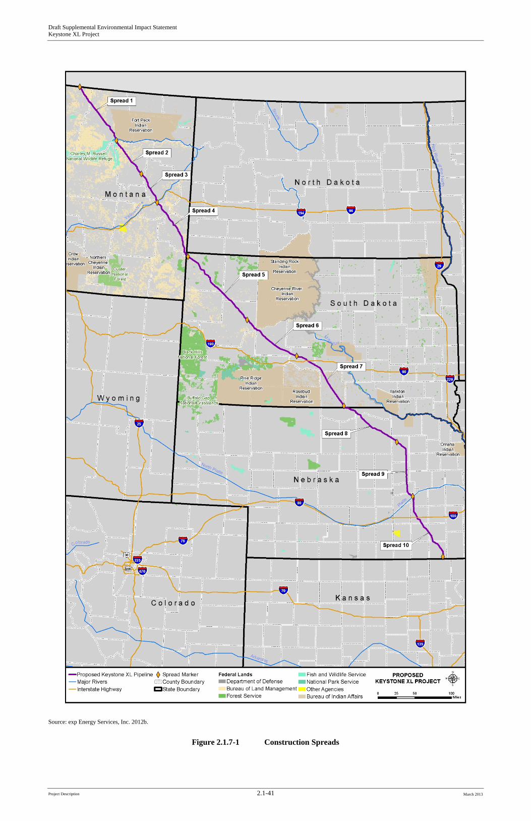
Once engineering surveys of the ROW centerline and additional TWAs have been finalized, and the acquisition of ROW easements and any necessary acquisitions of property-in-fee have been completed, construction would begin. As proposed, the pipeline would be constructed in 10 spreads (or sequences) of approximately 45 to 120 miles long (see Table 2.1-13). Final spread configurations and the final construction schedule may result in the use of additional spreads or fewer shorter or longer spreads. Figure 2.1.7-1 depicts the approximate location of each spread.
Project Description 2.1-38 March 2013
Draft Supplemental Environmental Impact Statement Keystone XL Project
Table 2.1-13 Pipeline Construction Spreads Associated with the Proposed Project
State Miles by
State County Spread Number Location
(Mile Post)
Approximate Length of
Construction Spread (Miles)
Montana 285.65
Phillips, Valley Spread 1 0-90 90 Valley, McCone Spread 2 90-151.48 61.48 McCone, Dawson Spread 3 151.48-197.68 46.2 Dawson, Prairie, Fallon Spread 4
South Dakota 315.29
Harding 197.68-288.63 90.95 Harding, Butte, Perkins, Meade Spread 5 288.63-410.75 122.12 Meade, Pennington Spread 6 Haakon, Jones 410.75-500.44 89.69 Jones, Lyman, Tripp Spread 7 500.44-598.86 98.42 Tripp, Gregory Spread 8
Nebraska 274.44 Keya Paha, Boyd, Holt, Antelope 598.86-691.78 92.92 Antelope, Boone, Nance, Merrick, Polk Spread 9 691.78-775.67 83.89 Polk, York, Fillmore, Saline, Jefferson Spread 10 775.67-875.38 99.71
Source: exp Energy Services, Inc. 2012a.
Project Description 2.1-39 March 2013
Draft Supplemental Environmental Impact Statement Keystone XL Project
Pipeline Construction Sequence Figure 2.1.7-2 shows a typical pipeline construction sequence. The design and construction of the pipeline would incorporate each of these steps. Additionally, the proposed Project would include additional construction for access roads, construction work camps, and temporary workspace facilities. All aspects of proposed Project construction are addressed in the remaining sections of this section.
Standard pipeline construction is composed of specific activities, including survey and staking of the ROW, clearing and grading, pipe stringing, bending, trenching, welding, lowering in, backfilling, hydrostatic testing, and cleanup. In addition to standard pipeline construction methods, special construction techniques would be used where warranted by site-specific conditions. These special techniques would be used when constructing across rugged terrain, sensitive areas, waterbodies, wetlands, paved roads, highways, and railroads (see Section 2.1.8, Special Pipeline Construction Procedures).
Construction would be planned to continue into the early winter months for as long as possible without the use of special winter construction techniques. However, as stated in the CMRP (Appendix G), if the proposed Project is authorized and winter construction is necessary to meet construction deadlines, Keystone would consult with the relevant federal, state, and local regulatory agencies to determine what changes may be necessary in permits issued, what additional permits may be required, and to identify the procedures that would have to be incorporated into construction to avoid or minimize environmental impacts. Winter construction plans would be finalized based on those consultations and permit requirements. Normal construction activities would be conducted during daylight hours, with the following exceptions:
• Completion of critical tie-ins on the ROW may occur after daylight hours. Completion requires tie-in welds, non-destructive testing, and sufficient backfill to stabilize the ditch.
• HDD operations may be conducted after daylight hours, if determined by the contractor to be necessary to complete a certain location. In some cases, that work may be required continuously until the work is completed; this may last 24 continuous hours or longer. Such operations may include drilling and pull-back operation, depending upon the site and weather conditions, permit requirements, schedule, crew availability, and other factors. Prior to construction, the presence of residences in proximity to the proposed HDD activities would be determined. HDD activities would be conducted consistent with any applicable local noise ordinances.
• Hydrostatic testing operations may be conducted after daylight hours if determined by the contractor to be necessary to complete a certain location. In some cases, that work may be required continuously until the work is completed; this activity may take place for 24 continuous hours or longer.
• While not anticipated in typical operations, certain work may be required after the end of daylight hours due to weather conditions, for safety, or for other proposed Project requirements.
Project Description 2.1-40 March 2013
Draft Supplemental Environmental Impact Statement Keystone XL Project
Source: exp Energy Services, Inc. 2012b.
Figure 2.1.7-1 Construction Spreads
Project Description 2.1-41 March 2013

Draft Supplemental Environmental Impact Statement Keystone XL Project
-Page Intentionally Left Blank-
Project Description 2.1-42 March 2013
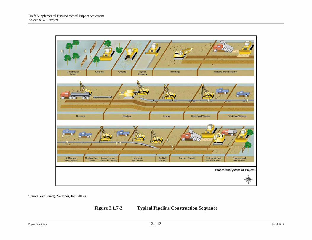
Draft Supplemental Environmental Impact Statement Keystone XL Project
Source: exp Energy Services, Inc. 2012a.
Figure 2.1.7-2 Typical Pipeline Construction Sequence
Project Description 2.1-43 March 2013
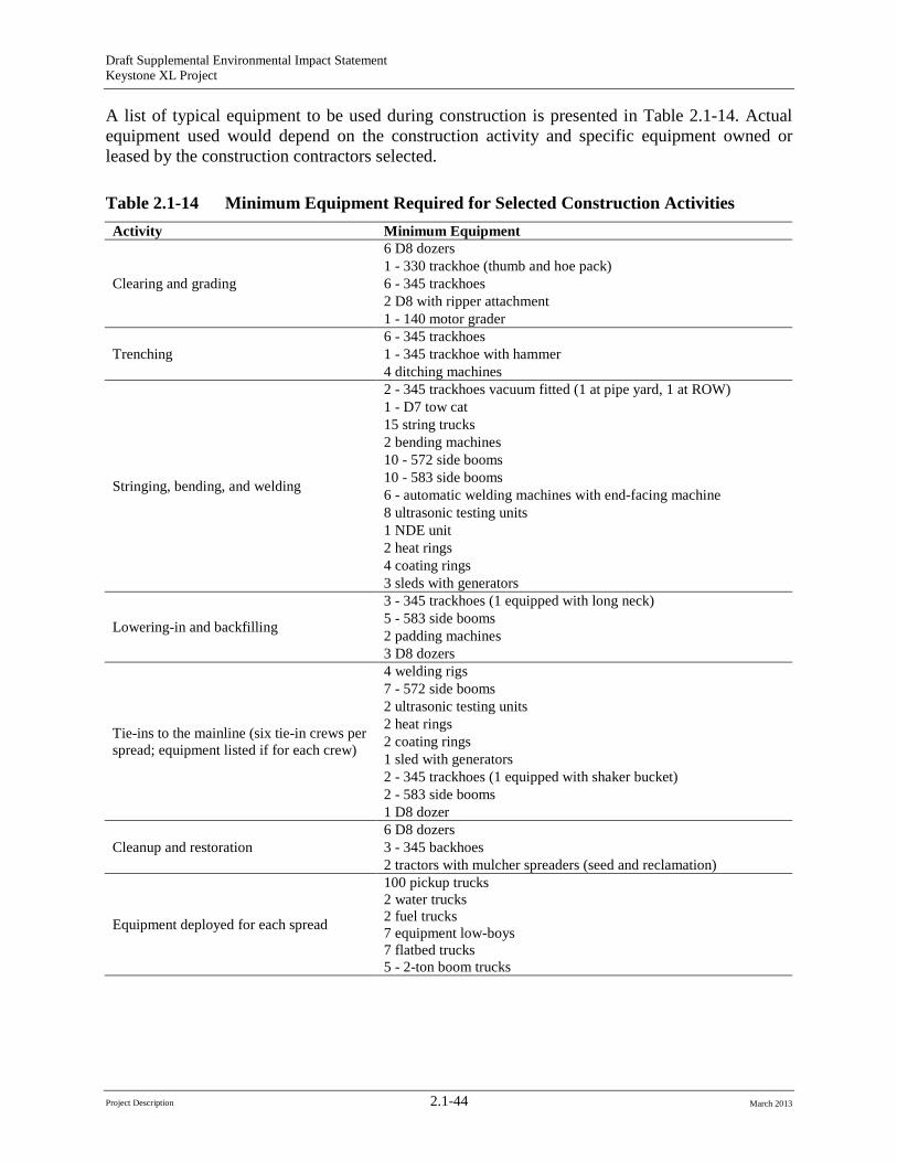
Draft Supplemental Environmental Impact Statement Keystone XL Project
A list of typical equipment to be used during construction is presented in Table 2.1-14. Actual equipment used would depend on the construction activity and specific equipment owned or leased by the construction contractors selected.
Table 2.1-14 Minimum Equipment Required for Selected Construction Activities Activity Minimum Equipment
Clearing and grading
6 D8 dozers 1 - 330 trackhoe (thumb and hoe pack) 6 - 345 trackhoes 2 D8 with ripper attachment 1 - 140 motor grader
Trenching 6 - 345 trackhoes 1 - 345 trackhoe with hammer 4 ditching machines
Stringing, bending, and welding
2 - 345 trackhoes vacuum fitted (1 at pipe yard, 1 at ROW) 1 - D7 tow cat 15 string trucks 2 bending machines 10 - 572 side booms 10 - 583 side booms 6 - automatic welding machines with end-facing machine 8 ultrasonic testing units 1 NDE unit 2 heat rings 4 coating rings 3 sleds with generators
Lowering-in and backfilling
3 - 345 trackhoes (1 equipped with long neck) 5 - 583 side booms 2 padding machines 3 D8 dozers
Tie-ins to the mainline (six tie-in crews per spread; equipment listed if for each crew)
4 welding rigs 7 - 572 side booms 2 ultrasonic testing units 2 heat rings 2 coating rings 1 sled with generators 2 - 345 trackhoes (1 equipped with shaker bucket) 2 - 583 side booms 1 D8 dozer
Cleanup and restoration 6 D8 dozers 3 - 345 backhoes 2 tractors with mulcher spreaders (seed and reclamation)
Equipment deployed for each spread
100 pickup trucks 2 water trucks 2 fuel trucks 7 equipment low-boys 7 flatbed trucks 5 - 2-ton boom trucks
Project Description 2.1-44 March 2013
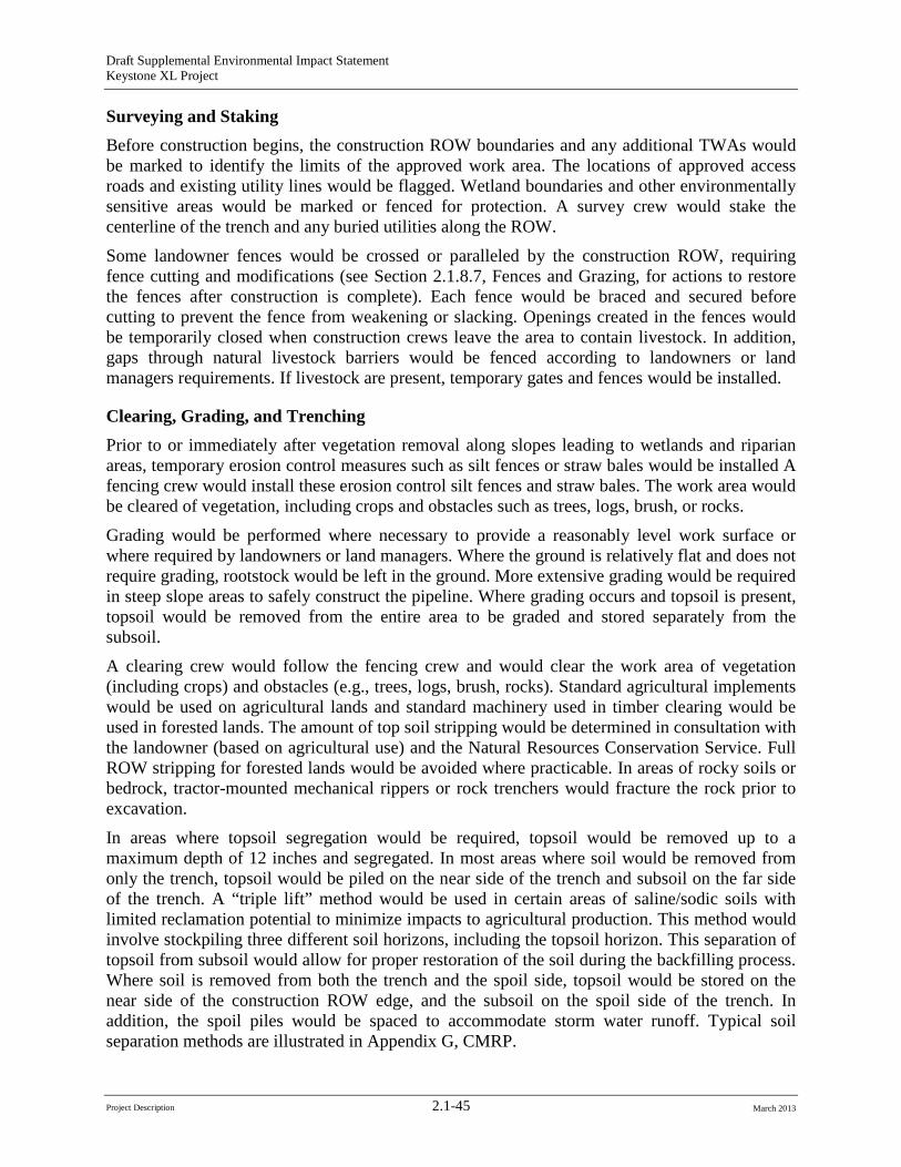
Draft Supplemental Environmental Impact Statement Keystone XL Project
Surveying and Staking Before construction begins, the construction ROW boundaries and any additional TWAs would be marked to identify the limits of the approved work area. The locations of approved access roads and existing utility lines would be flagged. Wetland boundaries and other environmentally sensitive areas would be marked or fenced for protection. A survey crew would stake the centerline of the trench and any buried utilities along the ROW.
Some landowner fences would be crossed or paralleled by the construction ROW, requiring fence cutting and modifications (see Section 2.1.8.7, Fences and Grazing, for actions to restore the fences after construction is complete). Each fence would be braced and secured before cutting to prevent the fence from weakening or slacking. Openings created in the fences would be temporarily closed when construction crews leave the area to contain livestock. In addition, gaps through natural livestock barriers would be fenced according to landowners or land managers requirements. If livestock are present, temporary gates and fences would be installed.
Clearing, Grading, and Trenching Prior to or immediately after vegetation removal along slopes leading to wetlands and riparian areas, temporary erosion control measures such as silt fences or straw bales would be installed A fencing crew would install these erosion control silt fences and straw bales. The work area would be cleared of vegetation, including crops and obstacles such as trees, logs, brush, or rocks.
Grading would be performed where necessary to provide a reasonably level work surface or where required by landowners or land managers. Where the ground is relatively flat and does not require grading, rootstock would be left in the ground. More extensive grading would be required in steep slope areas to safely construct the pipeline. Where grading occurs and topsoil is present, topsoil would be removed from the entire area to be graded and stored separately from the subsoil.
A clearing crew would follow the fencing crew and would clear the work area of vegetation (including crops) and obstacles (e.g., trees, logs, brush, rocks). Standard agricultural implements would be used on agricultural lands and standard machinery used in timber clearing would be used in forested lands. The amount of top soil stripping would be determined in consultation with the landowner (based on agricultural use) and the Natural Resources Conservation Service. Full ROW stripping for forested lands would be avoided where practicable. In areas of rocky soils or bedrock, tractor-mounted mechanical rippers or rock trenchers would fracture the rock prior to excavation.
In areas where topsoil segregation would be required, topsoil would be removed up to a maximum depth of 12 inches and segregated. In most areas where soil would be removed from only the trench, topsoil would be piled on the near side of the trench and subsoil on the far side of the trench. A “triple lift” method would be used in certain areas of saline/sodic soils with limited reclamation potential to minimize impacts to agricultural production. This method would involve stockpiling three different soil horizons, including the topsoil horizon. This separation of topsoil from subsoil would allow for proper restoration of the soil during the backfilling process. Where soil is removed from both the trench and the spoil side, topsoil would be stored on the near side of the construction ROW edge, and the subsoil on the spoil side of the trench. In addition, the spoil piles would be spaced to accommodate storm water runoff. Typical soil separation methods are illustrated in Appendix G, CMRP.
Project Description 2.1-45 March 2013
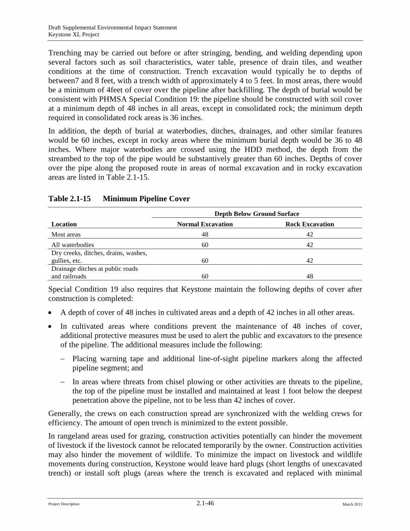
Draft Supplemental Environmental Impact Statement Keystone XL Project
Trenching may be carried out before or after stringing, bending, and welding depending upon several factors such as soil characteristics, water table, presence of drain tiles, and weather conditions at the time of construction. Trench excavation would typically be to depths of between7 and 8 feet, with a trench width of approximately 4 to 5 feet. In most areas, there would be a minimum of 4feet of cover over the pipeline after backfilling. The depth of burial would be consistent with PHMSA Special Condition 19: the pipeline should be constructed with soil cover at a minimum depth of 48 inches in all areas, except in consolidated rock; the minimum depth required in consolidated rock areas is 36 inches.
In addition, the depth of burial at waterbodies, ditches, drainages, and other similar features would be 60 inches, except in rocky areas where the minimum burial depth would be 36 to 48 inches. Where major waterbodies are crossed using the HDD method, the depth from the streambed to the top of the pipe would be substantively greater than 60 inches. Depths of cover over the pipe along the proposed route in areas of normal excavation and in rocky excavation areas are listed in Table 2.1-15.
Table 2.1-15 Minimum Pipeline Cover
Location Depth Below Ground Surface
Normal Excavation Rock Excavation Most areas 48 42 All waterbodies 60 42 Dry creeks, ditches, drains, washes, gullies, etc. 60 42 Drainage ditches at public roads and railroads 60 48
Special Condition 19 also requires that Keystone maintain the following depths of cover after construction is completed:
• A depth of cover of 48 inches in cultivated areas and a depth of 42 inches in all other areas.
• In cultivated areas where conditions prevent the maintenance of 48 inches of cover, additional protective measures must be used to alert the public and excavators to the presence of the pipeline. The additional measures include the following:
− Placing warning tape and additional line-of-sight pipeline markers along the affected pipeline segment; and
− In areas where threats from chisel plowing or other activities are threats to the pipeline, the top of the pipeline must be installed and maintained at least 1 foot below the deepest penetration above the pipeline, not to be less than 42 inches of cover.
Generally, the crews on each construction spread are synchronized with the welding crews for efficiency. The amount of open trench is minimized to the extent possible.
In rangeland areas used for grazing, construction activities potentially can hinder the movement of livestock if the livestock cannot be relocated temporarily by the owner. Construction activities may also hinder the movement of wildlife. To minimize the impact on livestock and wildlife movements during construction, Keystone would leave hard plugs (short lengths of unexcavated trench) or install soft plugs (areas where the trench is excavated and replaced with minimal
Project Description 2.1-46 March 2013
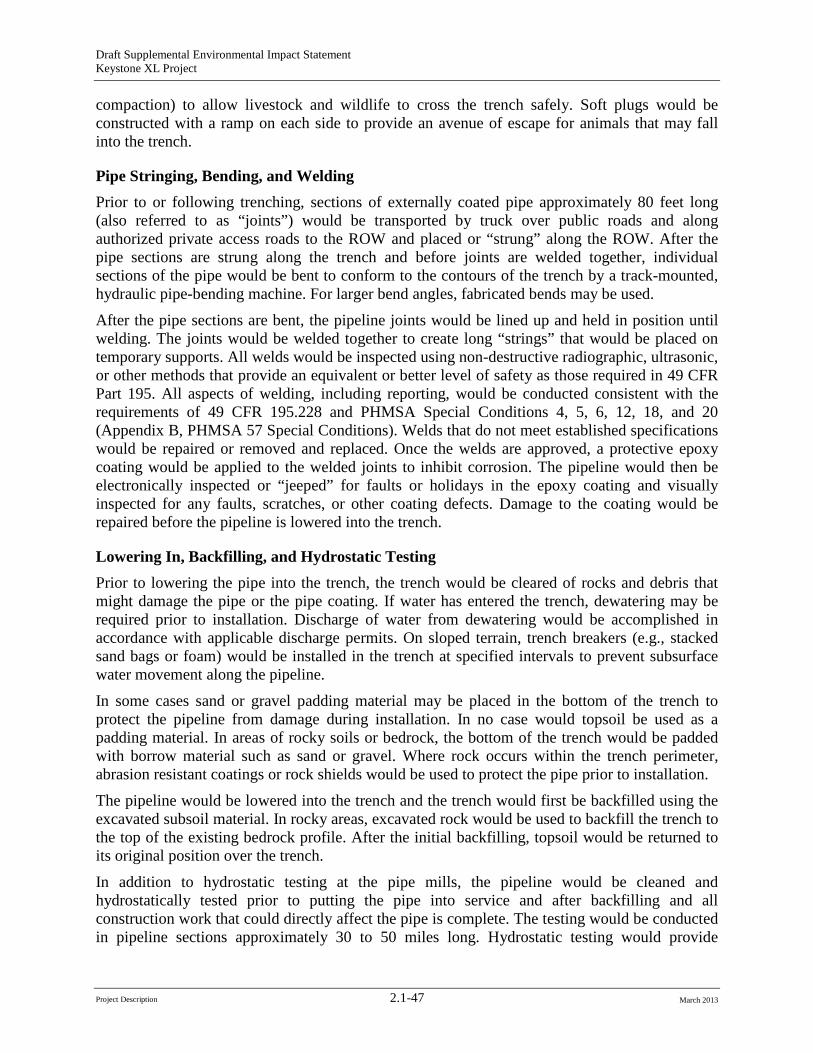
Draft Supplemental Environmental Impact Statement Keystone XL Project
compaction) to allow livestock and wildlife to cross the trench safely. Soft plugs would be constructed with a ramp on each side to provide an avenue of escape for animals that may fall into the trench.
Pipe Stringing, Bending, and Welding Prior to or following trenching, sections of externally coated pipe approximately 80 feet long (also referred to as “joints”) would be transported by truck over public roads and along authorized private access roads to the ROW and placed or “strung” along the ROW. After the pipe sections are strung along the trench and before joints are welded together, individual sections of the pipe would be bent to conform to the contours of the trench by a track-mounted, hydraulic pipe-bending machine. For larger bend angles, fabricated bends may be used.
After the pipe sections are bent, the pipeline joints would be lined up and held in position until welding. The joints would be welded together to create long “strings” that would be placed on temporary supports. All welds would be inspected using non-destructive radiographic, ultrasonic, or other methods that provide an equivalent or better level of safety as those required in 49 CFR Part 195. All aspects of welding, including reporting, would be conducted consistent with the requirements of 49 CFR 195.228 and PHMSA Special Conditions 4, 5, 6, 12, 18, and 20 (Appendix B, PHMSA 57 Special Conditions). Welds that do not meet established specifications would be repaired or removed and replaced. Once the welds are approved, a protective epoxy coating would be applied to the welded joints to inhibit corrosion. The pipeline would then be electronically inspected or “jeeped” for faults or holidays in the epoxy coating and visually inspected for any faults, scratches, or other coating defects. Damage to the coating would be repaired before the pipeline is lowered into the trench.
Lowering In, Backfilling, and Hydrostatic Testing Prior to lowering the pipe into the trench, the trench would be cleared of rocks and debris that might damage the pipe or the pipe coating. If water has entered the trench, dewatering may be required prior to installation. Discharge of water from dewatering would be accomplished in accordance with applicable discharge permits. On sloped terrain, trench breakers (e.g., stacked sand bags or foam) would be installed in the trench at specified intervals to prevent subsurface water movement along the pipeline.
In some cases sand or gravel padding material may be placed in the bottom of the trench to protect the pipeline from damage during installation. In no case would topsoil be used as a padding material. In areas of rocky soils or bedrock, the bottom of the trench would be padded with borrow material such as sand or gravel. Where rock occurs within the trench perimeter, abrasion resistant coatings or rock shields would be used to protect the pipe prior to installation.
The pipeline would be lowered into the trench and the trench would first be backfilled using the excavated subsoil material. In rocky areas, excavated rock would be used to backfill the trench to the top of the existing bedrock profile. After the initial backfilling, topsoil would be returned to its original position over the trench.
In addition to hydrostatic testing at the pipe mills, the pipeline would be cleaned and hydrostatically tested prior to putting the pipe into service and after backfilling and all construction work that could directly affect the pipe is complete. The testing would be conducted in pipeline sections approximately 30 to 50 miles long. Hydrostatic testing would provide
Project Description 2.1-47 March 2013
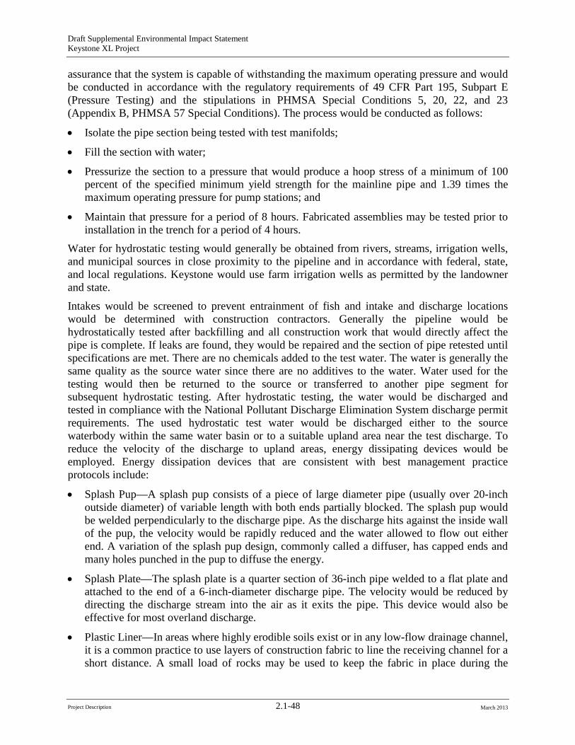
Draft Supplemental Environmental Impact Statement Keystone XL Project
assurance that the system is capable of withstanding the maximum operating pressure and would be conducted in accordance with the regulatory requirements of 49 CFR Part 195, Subpart E (Pressure Testing) and the stipulations in PHMSA Special Conditions 5, 20, 22, and 23 (Appendix B, PHMSA 57 Special Conditions). The process would be conducted as follows:
• Isolate the pipe section being tested with test manifolds;
• Fill the section with water;
• Pressurize the section to a pressure that would produce a hoop stress of a minimum of 100 percent of the specified minimum yield strength for the mainline pipe and 1.39 times the maximum operating pressure for pump stations; and
• Maintain that pressure for a period of 8 hours. Fabricated assemblies may be tested prior to installation in the trench for a period of 4 hours.
Water for hydrostatic testing would generally be obtained from rivers, streams, irrigation wells, and municipal sources in close proximity to the pipeline and in accordance with federal, state, and local regulations. Keystone would use farm irrigation wells as permitted by the landowner and state.
Intakes would be screened to prevent entrainment of fish and intake and discharge locations would be determined with construction contractors. Generally the pipeline would be hydrostatically tested after backfilling and all construction work that would directly affect the pipe is complete. If leaks are found, they would be repaired and the section of pipe retested until specifications are met. There are no chemicals added to the test water. The water is generally the same quality as the source water since there are no additives to the water. Water used for the testing would then be returned to the source or transferred to another pipe segment for subsequent hydrostatic testing. After hydrostatic testing, the water would be discharged and tested in compliance with the National Pollutant Discharge Elimination System discharge permit requirements. The used hydrostatic test water would be discharged either to the source waterbody within the same water basin or to a suitable upland area near the test discharge. To reduce the velocity of the discharge to upland areas, energy dissipating devices would be employed. Energy dissipation devices that are consistent with best management practice protocols include:
• Splash Pup—A splash pup consists of a piece of large diameter pipe (usually over 20-inch outside diameter) of variable length with both ends partially blocked. The splash pup would be welded perpendicularly to the discharge pipe. As the discharge hits against the inside wall of the pup, the velocity would be rapidly reduced and the water allowed to flow out either end. A variation of the splash pup design, commonly called a diffuser, has capped ends and many holes punched in the pup to diffuse the energy.
• Splash Plate—The splash plate is a quarter section of 36-inch pipe welded to a flat plate and attached to the end of a 6-inch-diameter discharge pipe. The velocity would be reduced by directing the discharge stream into the air as it exits the pipe. This device would also be effective for most overland discharge.
• Plastic Liner—In areas where highly erodible soils exist or in any low-flow drainage channel, it is a common practice to use layers of construction fabric to line the receiving channel for a short distance. A small load of rocks may be used to keep the fabric in place during the
Project Description 2.1-48 March 2013
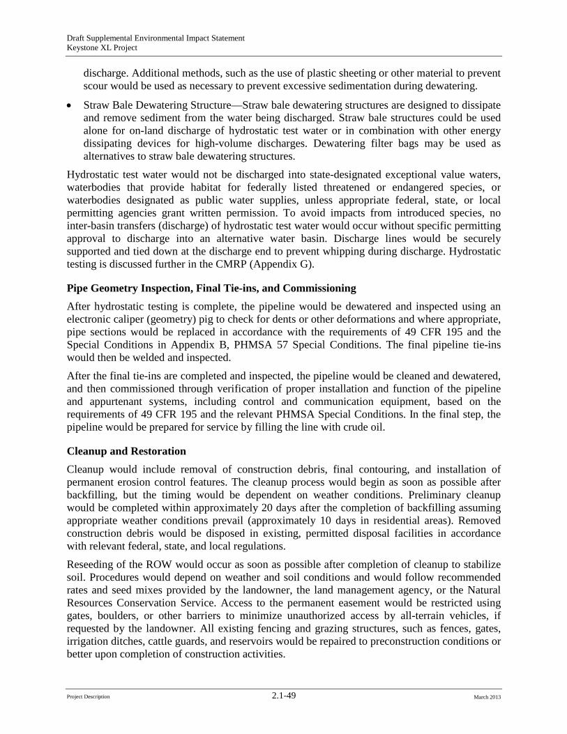
Draft Supplemental Environmental Impact Statement Keystone XL Project
discharge. Additional methods, such as the use of plastic sheeting or other material to prevent scour would be used as necessary to prevent excessive sedimentation during dewatering.
• Straw Bale Dewatering Structure—Straw bale dewatering structures are designed to dissipate and remove sediment from the water being discharged. Straw bale structures could be used alone for on-land discharge of hydrostatic test water or in combination with other energy dissipating devices for high-volume discharges. Dewatering filter bags may be used as alternatives to straw bale dewatering structures.
Hydrostatic test water would not be discharged into state-designated exceptional value waters, waterbodies that provide habitat for federally listed threatened or endangered species, or waterbodies designated as public water supplies, unless appropriate federal, state, or local permitting agencies grant written permission. To avoid impacts from introduced species, no inter-basin transfers (discharge) of hydrostatic test water would occur without specific permitting approval to discharge into an alternative water basin. Discharge lines would be securely supported and tied down at the discharge end to prevent whipping during discharge. Hydrostatic testing is discussed further in the CMRP (Appendix G).
Pipe Geometry Inspection, Final Tie-ins, and Commissioning After hydrostatic testing is complete, the pipeline would be dewatered and inspected using an electronic caliper (geometry) pig to check for dents or other deformations and where appropriate, pipe sections would be replaced in accordance with the requirements of 49 CFR 195 and the Special Conditions in Appendix B, PHMSA 57 Special Conditions. The final pipeline tie-ins would then be welded and inspected.
After the final tie-ins are completed and inspected, the pipeline would be cleaned and dewatered, and then commissioned through verification of proper installation and function of the pipeline and appurtenant systems, including control and communication equipment, based on the requirements of 49 CFR 195 and the relevant PHMSA Special Conditions. In the final step, the pipeline would be prepared for service by filling the line with crude oil.
Cleanup and Restoration Cleanup would include removal of construction debris, final contouring, and installation of permanent erosion control features. The cleanup process would begin as soon as possible after backfilling, but the timing would be dependent on weather conditions. Preliminary cleanup would be completed within approximately 20 days after the completion of backfilling assuming appropriate weather conditions prevail (approximately 10 days in residential areas). Removed construction debris would be disposed in existing, permitted disposal facilities in accordance with relevant federal, state, and local regulations.
Reseeding of the ROW would occur as soon as possible after completion of cleanup to stabilize soil. Procedures would depend on weather and soil conditions and would follow recommended rates and seed mixes provided by the landowner, the land management agency, or the Natural Resources Conservation Service. Access to the permanent easement would be restricted using gates, boulders, or other barriers to minimize unauthorized access by all-terrain vehicles, if requested by the landowner. All existing fencing and grazing structures, such as fences, gates, irrigation ditches, cattle guards, and reservoirs would be repaired to preconstruction conditions or better upon completion of construction activities.
Project Description 2.1-49 March 2013
Draft Supplemental Environmental Impact Statement Keystone XL Project
Keystone would also restrict access to the permanent easement using gates, boulders, or other barriers to minimize unauthorized access by all-terrain vehicles in wooded areas or other previously unfenced areas if requested by the landowner. Pipeline markers would be installed at road and railroad crossings and other locations (as required by 49 CFR 195) to show the location of the pipeline. Markers would identify the owner of the pipeline and convey emergency contact information. Special markers providing information and guidance to aerial patrol pilots also would be installed. Pipeline markers would be provided for identification of the pipeline location for safety purposes in accordance with the requirements of 49 CFR 195.410 (Line Markers) and PHMSA Special Condition 40 (see Appendix B, PHMSA 57 Special Conditions), including the following:
• Pipeline markers would be installed on both sides of all highways, roads, road ROWs, railroads, and waterbody crossings and in areas where the pipeline is buried less than 48 inches.
• Pipeline markers would be made from industrial strength materials to withstand abrasion from wind and damage from cattle.
• Pipeline markers would be installed at all fences.
• Pipeline markers would be installed along the ROW to provide line-of-sight marking of the pipeline, providing it is practical to do so and consistent with the type of land use, such that it does not hinder the use of the property by the landowner. Pipeline markers would be installed at all angle points, and at intermediate points, where practical, so that from any marker, the adjacent marker in either direction would be visible.
• Consideration would be given to installing additional markers, except where they would interfere with land use (e.g., farming).
• Aerial markers showing identifying numbers would be installed at approximately 5-mile intervals.
• At each MLV site and pump station, signs would be installed and maintained on the perimeter fence where the pipeline enters and exits the fenced area.
Markers would identify the owner of the pipeline and convey emergency contact information. Special markers providing information and guidance to aerial patrol pilots also would be installed. The markers would be maintained during the operating life of the proposed Project.
Post-construction Reclamation Monitoring and Response The ROW would be inspected after the first growing season to determine the success of revegetation and noxious weed control. Eroded areas would be repaired and areas that were unsuccessfully re-established would be revegetated by Keystone or Keystone would compensate the landowner for reseeding. The CMRP (Appendix G) provides information on revegetation and weed control procedures that Keystone would incorporate into the proposed Project.
2.1.8 Special Pipeline Construction Procedures Special construction techniques would be used when crossing roads, highways, and railroads; pipeline, utility, and other buried feature crossings; steep terrain; unstable soils; perennial waterbodies; wetlands; areas that require ripping; and residential and commercial areas. These
Project Description 2.1-50 March 2013
Draft Supplemental Environmental Impact Statement Keystone XL Project
special techniques are described below. Further discussion of impacts and mitigation measures for sensitive areas is provided in Chapter 4, Environmental Consequences.
2.1.8.1 Road, Highway, and Railroad Crossings Construction across paved roads, highways, and railroads would be in accordance with the requirements of the appropriate road and railroad crossing permits and approvals. In general, all major paved roads, all primary gravel roads, all highways, and all railroads would be crossed by boring beneath the road or railroad, as shown in Figure 2.1.8-1. Boring would result in minimal or no disruption to traffic at road or railroad crossings. Each boring would take 1 to 2 days for most roads and railroads, and 10 days for long crossings such as interstates or 4-lane highways.
Initially, a pit would be excavated on each side of the feature; boring equipment would be placed in the pit and a hole would be bored under the road at least equal to the diameter of the pipe and a prefabricated pipe section would be pulled through the borehole. For long crossings, sections would be welded onto the pipe string before being pulled through the borehole.
If permitted by local regulators and landowners, smaller gravel roads and driveways would likely be crossed using an open-cut method that would typically take between 1 and 2 days to complete. This would require temporary road closures and establishment of detours for traffic. If no reasonable detour is feasible, at least one lane of traffic would be kept open in most cases. Keystone would post signs at these open-cut crossings and would implement traffic control plans to reduce traffic disturbance and protect public safety.
2.1.8.2 Pipeline, Utility, and Other Buried Feature Crossings Keystone and its pipeline contractors would comply with USDOT regulations, utility agreements, and industry best management practices with respect to utility crossing and separation specifications. To the extent practicable, Keystone would avoid relocating existing electric transmission lines and would use existing distribution lines. Where line relocation cannot be avoided, Keystone would coordinate with the local public power district to temporarily or permanently relocate lines. One-call notification would be made for all utility crossings to identify utilities. Similarly, private landowners would be notified of planned construction activities so that buried features, such as irrigation systems and other waterlines, could be avoided or replaced. Prior to construction, each rancher with a stock watering or irrigation system or other waterlines would be asked to provide the location of any waterlines in the construction area. In the case of existing buried oil or gas pipelines, the owner of the facility would be asked to provide information on the locations of pipes in the construction area. Metallic pipelines would be physically located by a line locating crew prior to excavation.
Unless otherwise specified in a crossing agreement, the contractor would excavate to allow installation of the proposed Project pipeline across the existing pipeline or utility with a minimum clearance of 12 inches. The clearance distance would be filled with sandbags or suitable fill material to maintain the clearance. Backfill of the crossing would be compacted in lifts to ensure continuous support of the existing utility.
Project Description 2.1-51 March 2013
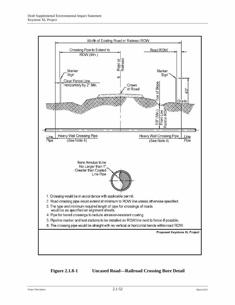
Draft Supplemental Environmental Impact Statement Keystone XL Project
Figure 2.1.8-1 Uncased Road—Railroad Crossing Bore Detail
Project Description 2.1-52 March 2013
Draft Supplemental Environmental Impact Statement Keystone XL Project
For some crossings, the owner of the utility or buried feature may require the facility to be excavated and exposed by their own employees prior to the Keystone contractor getting to the location. In those cases, Keystone would work with owners to complete work to the satisfaction of the owner. Where the owner of the utility does not require pre-excavation, generally, the pipeline contractor would locate and expose the utility before excavating the trench.
2.1.8.3 Steep Terrain Steep slopes traversed by the proposed route would be graded to reduce slope angles, thus allowing safer operation of construction equipment and reducing the degree of pipe bending required. In areas where the pipeline route crosses side slopes, cut-and-fill grading may be employed to obtain a safe working terrace. Keystone would install the pipeline to maintain the required depth of cover of 48 inches in cultivated areas and 42 inches in all other areas, including on side slope cuts and perpendicular slope crossings, except in bedrock areas where the minimum depth would be 36 inches.
Prior to cut-and-fill grading on steep terrain, topsoil would be stripped from the ROW and stockpiled. If soil and slope conditions permit, soil from the high side of the ROW would be excavated and moved to the low side to create a safer and more level working surface. After pipeline installation, soil from the low side of the ROW would be returned to the high side and the contour of the slope would be restored to its pre-construction condition to the degree practicable.
Temporary sediment barriers, such as silt fences and straw bales, would be installed where appropriate to prevent erosion and siltation of wetlands, waterbodies, or other environmentally sensitive areas. During grading, temporary slope breakers consisting of mounded and compacted soil would be installed across the ROW. In the cleanup phase, permanent slope breakers would be installed where appropriate. Section 4.5 of the CMRP (Appendix G) presents additional information on the use of sediment barriers and slope breakers.
After regrading and installation of erosion control devices, seed would be applied to steep slopes and mulch consisting of hay or non-brittle straw would be placed on the ROW, or the ROW would be protected with erosion control geofabrics. MDEQ requires that geofabric mesh size be 2 inches or greater to avoid animal entanglement. Sediment barriers would be maintained across the ROW until permanent vegetation is established. Additional temporary workspaces may be required for storage of graded material and/or topsoil during construction.
2.1.8.4 Unstable Soils Special construction techniques and environmental protection measures would be applied to areas with unstable soils and to areas with high potential for landslides, erosion, and mass wasting. Construction in these areas could require additional temporary workspace areas.
Topsoil piles would be protected from erosion through matting, mulching, watering, or tackifying (making slightly sticky by applying resin adhesives) to the extent practicable. Photodegradable matting would be placed on steep slopes or areas prone to extreme wind exposure, such as north- or west-facing slopes and ridge tops. Biodegradable pins would be used in place of metal staples to hold the matting in place.
Reseeding would be carried out using native seed mixes that are certified noxious weed-free, if possible. Land imprinting may be employed to create impressions in the soil to reduce erosion,
Project Description 2.1-53 March 2013
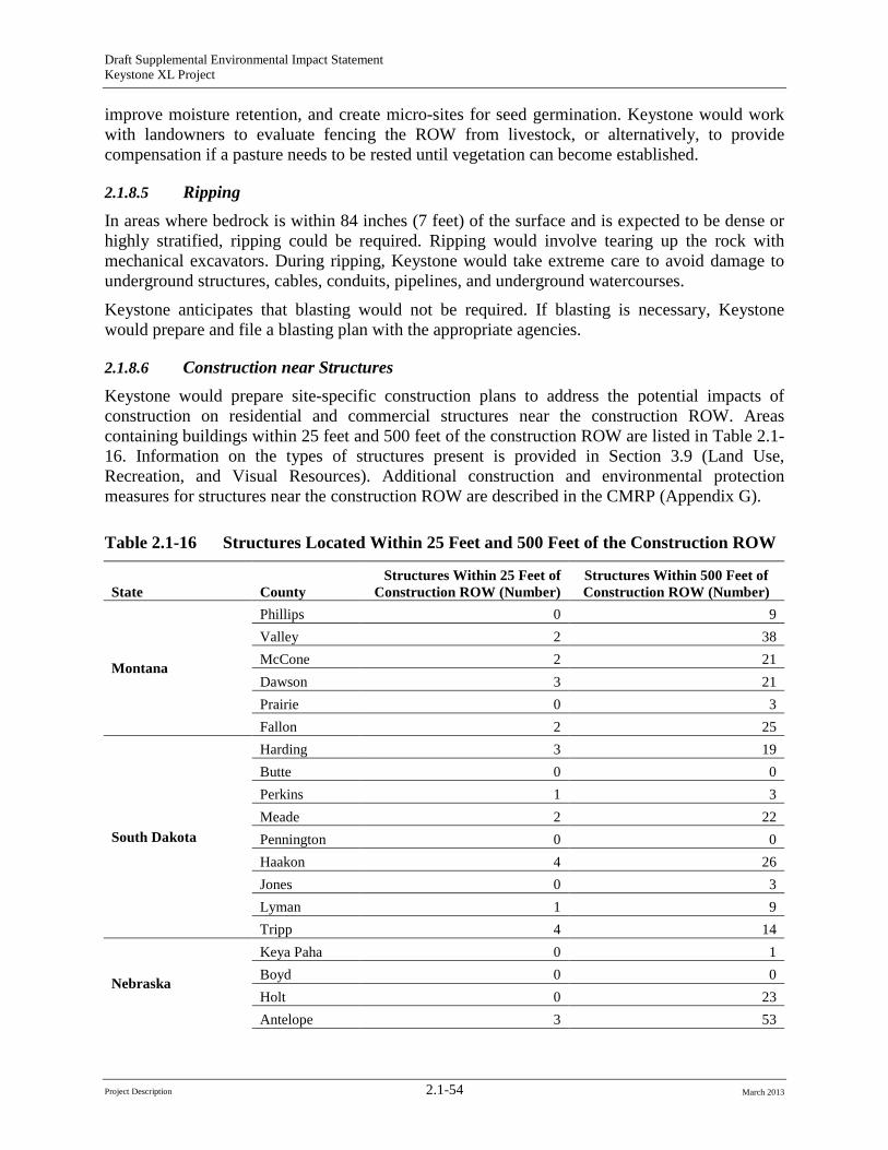
Draft Supplemental Environmental Impact Statement Keystone XL Project
improve moisture retention, and create micro-sites for seed germination. Keystone would work with landowners to evaluate fencing the ROW from livestock, or alternatively, to provide compensation if a pasture needs to be rested until vegetation can become established.
2.1.8.5 Ripping In areas where bedrock is within 84 inches (7 feet) of the surface and is expected to be dense or highly stratified, ripping could be required. Ripping would involve tearing up the rock with mechanical excavators. During ripping, Keystone would take extreme care to avoid damage to underground structures, cables, conduits, pipelines, and underground watercourses.
Keystone anticipates that blasting would not be required. If blasting is necessary, Keystone would prepare and file a blasting plan with the appropriate agencies.
2.1.8.6 Construction near Structures Keystone would prepare site-specific construction plans to address the potential impacts of construction on residential and commercial structures near the construction ROW. Areas containing buildings within 25 feet and 500 feet of the construction ROW are listed in Table 2.116. Information on the types of structures present is provided in Section 3.9 (Land Use, Recreation, and Visual Resources). Additional construction and environmental protection measures for structures near the construction ROW are described in the CMRP (Appendix G).
Table 2.1-16 Structures Located Within 25 Feet and 500 Feet of the Construction ROW
State County Structures Within 25 Feet of
Construction ROW (Number) Structures Within 500 Feet of Construction ROW (Number)
Montana
Phillips 0 9 Valley 2 38 McCone 2 21 Dawson 3 21 Prairie 0 3 Fallon 2 25
South Dakota
Harding 3 19 Butte 0 0 Perkins 1 3 Meade 2 22 Pennington 0 0 Haakon 4 26 Jones 0 3 Lyman 1 9 Tripp 4 14
Nebraska
Keya Paha 0 1 Boyd 0 0 Holt 0 23 Antelope 3 53
Project Description 2.1-54 March 2013
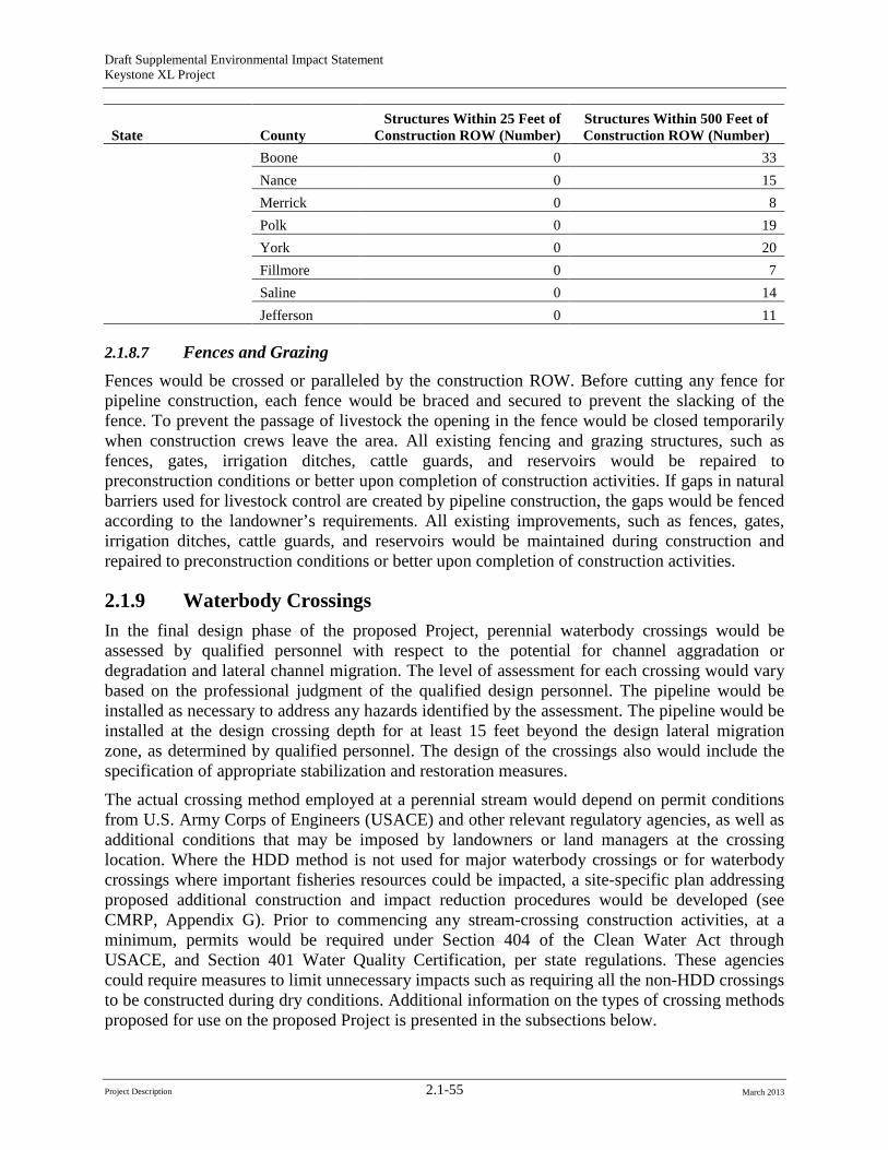
Draft Supplemental Environmental Impact Statement Keystone XL Project
State County
Structures Within 25 Feet of Construction ROW (Number)
Structures Within 500 Feet of Construction ROW (Number)
Boone 0 33 Nance 0 15 Merrick 0 8 Polk 0 19 York 0 20 Fillmore 0 7 Saline 0 14 Jefferson 0 11
2.1.8.7 Fences and Grazing Fences would be crossed or paralleled by the construction ROW. Before cutting any fence for pipeline construction, each fence would be braced and secured to prevent the slacking of the fence. To prevent the passage of livestock the opening in the fence would be closed temporarily when construction crews leave the area. All existing fencing and grazing structures, such as fences, gates, irrigation ditches, cattle guards, and reservoirs would be repaired to preconstruction conditions or better upon completion of construction activities. If gaps in natural barriers used for livestock control are created by pipeline construction, the gaps would be fenced according to the landowner’s requirements. All existing improvements, such as fences, gates, irrigation ditches, cattle guards, and reservoirs would be maintained during construction and repaired to preconstruction conditions or better upon completion of construction activities.
2.1.9 Waterbody Crossings In the final design phase of the proposed Project, perennial waterbody crossings would be assessed by qualified personnel with respect to the potential for channel aggradation or degradation and lateral channel migration. The level of assessment for each crossing would vary based on the professional judgment of the qualified design personnel. The pipeline would be installed as necessary to address any hazards identified by the assessment. The pipeline would be installed at the design crossing depth for at least 15 feet beyond the design lateral migration zone, as determined by qualified personnel. The design of the crossings also would include the specification of appropriate stabilization and restoration measures.
The actual crossing method employed at a perennial stream would depend on permit conditions from U.S. Army Corps of Engineers (USACE) and other relevant regulatory agencies, as well as additional conditions that may be imposed by landowners or land managers at the crossing location. Where the HDD method is not used for major waterbody crossings or for waterbody crossings where important fisheries resources could be impacted, a site-specific plan addressing proposed additional construction and impact reduction procedures would be developed (see CMRP, Appendix G). Prior to commencing any stream-crossing construction activities, at a minimum, permits would be required under Section 404 of the Clean Water Act through USACE, and Section 401 Water Quality Certification, per state regulations. These agencies could require measures to limit unnecessary impacts such as requiring all the non-HDD crossings to be constructed during dry conditions. Additional information on the types of crossing methods proposed for use on the proposed Project is presented in the subsections below.
Project Description 2.1-55 March 2013
Draft Supplemental Environmental Impact Statement Keystone XL Project
In addition to the proposed pipeline crossings of waterbodies, there would be temporary equipment bridges installed across many waterways. The actual crossing method employed would depend on any permit conditions from USACE and other relevant regulatory agencies. Prior to the start of clearing along each pipeline construction spread, temporary bridges (e.g., subsoil fill over culverts, timber mats supported by flumes, railcar flatbeds, or flexi-float apparatus) would be installed across all perennial waterbodies to allow construction equipment to cross with reduced disturbance. Clearing crews would be allowed only one pass through the waterbodies prior to temporary bridge construction. All other construction equipment would be required to use the bridges. Waterbodies would be crossed using one of four different open-cut methods or the HDD method. These waterbody crossing methods are described below.
2.1.9.1 Open-Cut Crossing Methods For most waterbodies to be crossed by the proposed Project, one of the open-cut methods listed below would be used:
• Non-flowing open-cut crossing method (for waterbodies that do not have a perceptible flow at the time of construction);
• Flowing open-cut crossing method;
• Dry-flume open-cut method; or
• Dry dam-and-pump open-cut method.
The trenching, pipeline installation, and backfilling methods used for these types of crossings would be similar to the crossing methods described above.
Non-Flowing Open-Cut Crossing Method The non-flowing open-cut method would be used for all waterbodies with no visible flow at the time of construction. In the event that intermittent waterbodies are dry or have non-moving water at the time of crossing, Keystone would install the pipeline using this method. Detail 11 of the CMRP (Appendix G) is an illustration of a typical open-cut crossing method for non-flowing waterbodies.
Flowing Open-Cut Crossing Method If there is flow at the time of construction, the flowing open-cut method would be used and the trench would be excavated through flowing water. If an intermittent waterbody is flowing when crossed, Keystone would install the pipeline using this method. Backhoes operating from one or both banks would excavate the trench within the streambed while water continues to flow through the construction work area (see Detail 12 of Appendix G, CMRP). In wider rivers, in-stream operation of equipment may be necessary. Keystone would trench through the channel, lower in a pipe that is weighted for negative buoyancy, then backfill. The need for negative buoyancy would be determined by detailed design and site-specific considerations at the time of construction. Material excavated from the trench generally would be placed at least 10 feet away from the water’s edge unless stream width exceeds the reach of the excavation equipment. Sediment barriers would be installed where necessary to prevent excavated spoil from entering the water. Hard or soft trench plugs would be placed to prevent the flow of water into the upland portions of the trench. After installation, the grade would be restored to pre-construction
Project Description 2.1-56 March 2013
Draft Supplemental Environmental Impact Statement Keystone XL Project
condition, topsoil would be replaced (unless saturated conditions exist), and permanent erosion control devices would be installed.
For this crossing type, pipe segments for each crossing would be welded and positioned adjacent to the waterbody. After the trench is excavated, the pipeline segment would be carried, pushed, or pulled across the waterbody and positioned in the trench. The trench would be backfilled with native material or with imported material if required by permits.
Keystone would minimize the time of in-stream construction to reduce impacts to waterbody channel and banks. For minor waterbodies (less than 10 feet wide at the water’s edge), the trenching and backfill of the crossing would typically require no more than 24 hours; intermediate waterbodies (10 to 100-feet-wide) would typically require no more than 48 hours. Major waterbodies (more than 100-feet-wide) would be crossed as quickly as possible. It is possible that the time required to accomplish the crossings of major waterbodies could exceed 48 hours.
Dry-Flume Open-Cut Method Keystone would use the dry-flume method on selected environmentally sensitive waterbodies where technically feasible. To the extent practicable, non-flowing open cut crossings would be the preferred crossing method. The dry-flume method is used for sensitive, relatively narrow waterbodies free of large rocks and bedrock at the trench line and with a relatively straight channel across the construction ROW. Use of this method involves installing dams upstream and downstream of the construction area and installing one or more pipes (flumes) that would extend along the course of the waterbody and through both dams. Stream flow would be carried through the construction area by the flume pipe(s).
Keystone would install flumes with sufficient capacity to transport the maximum flows that could be generated seasonally within the waterbody. The flumes, typically 40 to 60 feet long, would be installed before trenching and aligned to prevent impounding of water upstream of the construction area or to cause back-erosion downstream.
The upstream and downstream ends of the flumes would be incorporated into dams made of sandbags and plastic sheeting (or equivalent material). Upstream dams would be installed first and would funnel stream flow into the flumes. Downstream dams then would be constructed to prevent water from flowing back into the area to be trenched. The flumes would remain in place during pipeline installation, backfilling, and streambank restoration.
Prior to trenching, the area between the dams typically would be dewatered. Backhoes working from one or both banks, or from within the isolated waterbody bed, would excavate the trench across the waterbody and under the flume pipes. Discharge of water from dewatering would be accomplished in accordance with applicable discharge permits. Excavated material would be stockpiled on the upland construction ROW at least 10 feet from the water’s edge or in the extra workspaces. Sediment containment devices, such as silt fences and straw bales, would be installed to contain the excavated material and minimize the potential for sediment to migrate into the waterbody.
After the trench is excavated to the proper depth, a prefabricated section of pipe would be positioned and lowered into the trench. The trench then would be backfilled with the excavated material from the stream unless otherwise specified in stream crossing permits. Prior to removing the dams and flume pipes and restoring stream flow, water that accumulated in the construction
Project Description 2.1-57 March 2013
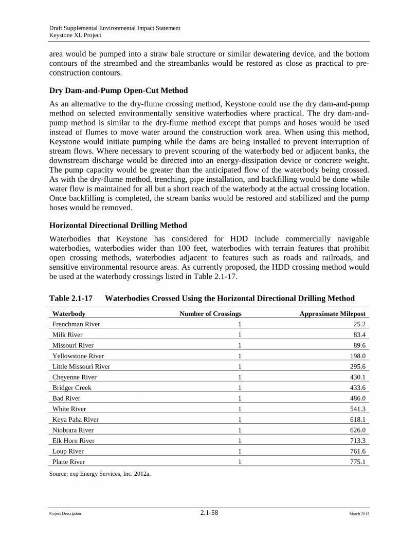
Draft Supplemental Environmental Impact Statement Keystone XL Project
area would be pumped into a straw bale structure or similar dewatering device, and the bottom contours of the streambed and the streambanks would be restored as close as practical to pre-construction contours.
Dry Dam-and-Pump Open-Cut Method As an alternative to the dry-flume crossing method, Keystone could use the dry dam-and-pump method on selected environmentally sensitive waterbodies where practical. The dry dam-andpump method is similar to the dry-flume method except that pumps and hoses would be used instead of flumes to move water around the construction work area. When using this method, Keystone would initiate pumping while the dams are being installed to prevent interruption of stream flows. Where necessary to prevent scouring of the waterbody bed or adjacent banks, the downstream discharge would be directed into an energy-dissipation device or concrete weight. The pump capacity would be greater than the anticipated flow of the waterbody being crossed. As with the dry-flume method, trenching, pipe installation, and backfilling would be done while water flow is maintained for all but a short reach of the waterbody at the actual crossing location. Once backfilling is completed, the stream banks would be restored and stabilized and the pump hoses would be removed.
Horizontal Directional Drilling Method Waterbodies that Keystone has considered for HDD include commercially navigable waterbodies, waterbodies wider than 100 feet, waterbodies with terrain features that prohibit open crossing methods, waterbodies adjacent to features such as roads and railroads, and sensitive environmental resource areas. As currently proposed, the HDD crossing method would be used at the waterbody crossings listed in Table 2.1-17.
Table 2.1-17 Waterbodies Crossed Using the Horizontal Directional Drilling Method
Waterbody Number of Crossings Approximate Milepost Frenchman River 1 25.2 Milk River 1 83.4 Missouri River 1 89.6 Yellowstone River 1 198.0 Little Missouri River 1 295.6 Cheyenne River 1 430.1 Bridger Creek 1 433.6 Bad River 1 486.0 White River 1 541.3 Keya Paha River 1 618.1 Niobrara River 1 626.0 Elk Horn River 1 713.3 Loup River 1 761.6 Platte River 1 775.1
Source: exp Energy Services, Inc. 2012a.
Project Description 2.1-58 March 2013
Draft Supplemental Environmental Impact Statement Keystone XL Project
The HDD method could also be used to bore beneath terrestrial areas that contain special resources that require avoidance. Additional HDD crossings could be incorporated into the proposed Project as a result of resource agency, landowner, or land manager concerns, as well as due to construction-related issues.
The HDD method involves drilling a pilot hole under the waterbody and banks, then enlarging the hole through successive ream borings with progressively larger bits until the hole is large enough to accommodate a pre-welded segment of pipe. Throughout the process of drilling and enlarging the hole, a water-bentonite slurry would be circulated to lubricate the drilling tools, remove drill cuttings, and provide stability to the drilled holes. Pipe sections long enough to span the entire crossing would be staged and welded along the construction work area on the opposite side of the waterbody and then pulled through the drilled hole.
The welded drill string would be hydrostatically tested for 4 hours prior to being pulled into place. Depending on the angle of approach of the pipeline alignment to the water crossing, a “false ROW” may need to be cleared on the pull back side to allow pipe placement at the appropriate angle to the waterbody. Keystone has created Site-Specific Waterbody Crossing Plans (Appendix G, CMRP) that describe the procedures to be used at each perennial waterbody crossed using the HDD method. Keystone would use industry standard procedures to ensure pipe and coating integrity are maintained during HDD installations.
During HDD operations, the hole that is reamed to allow the pipeline to be pulled through is much larger than the pipe diameter (approximately a 42-inch-diameter hole or larger for the 36inch-diameter pipe). As noted above, bentonite drilling mud would be used to reduce friction and provide lubrication and buoyancy for the pipe during the pull back, assuring minimal contact with the walls of the drill hole.5
5 See Section 4.3, Water Resources.
An abrasion-resistant overcoat would be applied to the FBE coating on the pipe joints designated for HDDs. This overcoat prevents damage to the corrosion resistant FBE coating as the pipe is pulled through the bored hole. After installation, Keystone would conduct CP and in-line inspection surveys to determine if any damage may have resulted to the pipe coating during the construction process.
There is a potential for HDD frac-outs (accidental releases of pressurized drilling mud from the borehole) to occur during construction. A frac-out could release bentonite drilling mud into the aquatic environment. Bentonite is non-toxic; the released drilling mud would disperse in flowing water or eventually settle in standing water. The proposed minimum depth for HDD pipeline sections is 25 feet below the streambed. In some instances, the pressurized fluids and drilling lubricants used in the HDD process may escape the active bore, migrate through the soils, and come to the surface at or near the construction site, an event commonly known as a frac-out. While the HDD method poses a small risk of frac-out (i.e., release of bentonite-based drilling fluids), potential releases would be contained by best management practices that are described within the HDD Contingency Plans required for drilled crossings and prepared by the pipeline contractor prior to construction. These practices include monitoring of the directional drill, monitoring downstream for evidence of drilling fluids, and mitigation measures to address a fracout should one occur.
Most leaks of HDD drilling fluids occur near the entry and exit locations for the drill and are quickly contained and cleaned up. Frac-outs that may release drilling fluids into aquatic
Project Description 2.1-59 March 2013
Draft Supplemental Environmental Impact Statement Keystone XL Project
environments are difficult to contain primarily because bentonite readily disperses in flowing water and quickly settles in standing water. Further discussion of frac-outs is presented in Section 4.3, Water Resources; Section 4.7, Fisheries; and Section 4.8, Threatened and Endangered Species and Species of Conservation Concern.
2.1.9.2 Wetland Crossings Construction across wetlands would be similar to typical conventional upland cross-country construction, with modifications to reduce the potential for effects to wetland hydrology and soil structure. The wetland crossing methods used would depend largely on the stability of the soils at the crossing location at the time of construction. The 110-foot pipeline construction corridor width would be reduced to 85 feet for wetlands in Montana and Nebraska, and 75 feet for wetlands in South Dakota, unless conditions require a wider construction corridor. In instances where the wetland is supersaturated or inundated, the corridor ROW may be increased to ensure safe construction conditions. The operation ROW would be 30 feet in all three states, unless conditions require a wider permanent ROW width.
If wetland soils are not excessively saturated at the time of construction and can support construction equipment without equipment mats, construction would occur in a manner similar to conventional upland cross-country construction techniques. Low ground pressure equipment or conventional equipment supported by pre-fabricated matting would be used in all wetlands. Where wetlands are located at the base of slopes, permanent slope breakers would be constructed across the ROW in upland areas adjacent to the wetland boundary. Temporary sediment barriers would be installed where necessary until revegetation of adjacent upland areas is successful. Additional TWAs would be required on both sides of saturated or inundated wetlands to stage construction, fabricate the pipeline, and store materials. These additional TWAs would be located in upland areas a minimum of 10 feet from the wetland edge. More information is located in the Site-Specific Waterbody Crossing Plans located in the CMRP (Appendix G) with recommended modifications to the CMRP provided in Section 4.4.4, Recommended Additional Mitigation.
Clearing of vegetation in wetlands within the construction corridor would be limited to trees and shrubs, which would be cut flush with the surface of the ground, leaving the root stock in place, and removed from the wetland. Scrub-shrub and forested communities would be allowed to regenerate outside of the maintained operations ROW, and in areas where HDD was used to span open water areas. To avoid excessive disruption of wetland soils and the native seed and rootstock within the wetland soils, stump removal, grading, topsoil segregation, and excavation would be limited to the area immediately over the trench line to the maximum extent practicable. Trench breakers would be installed where necessary to prevent the subsurface drainage of water from wetlands. Trench width may vary in some wetlands to provide an even, safe work area, which depends upon topography, soil moisture content, and groundwater levels. Severe topography may require additional disturbance to create an even safe work area. More saturated soils usually require a wider trench in order to maintain a safe ditch and to avoid unstable trench walls. During clearing, sediment barriers, such as silt fence and staked straw bales, would be installed and maintained on down slopes adjacent to all wetlands and within additional TWAs, as necessary, to minimize the potential for sediment runoff.
Construction equipment working in all wetlands would be limited to the area essential for clearing the ROW, excavating the trench, fabricating and installing the pipeline, backfilling the
Project Description 2.1-60 March 2013
Draft Supplemental Environmental Impact Statement Keystone XL Project
trench, and restoring the ROW. In areas where there is no reasonable access to the ROW except through wetlands, non-essential equipment would be allowed to travel through wetlands only if the ground is firm enough or has been stabilized with approved pre-fabricated matting (not timber slash) to avoid rutting. Where wetland soils are supersaturated or inundated, the pipeline could be installed using the push-pull technique. The push-pull installation process would involve stringing and welding the pipeline outside of the wetland, and excavating and backfilling the trench using a backhoe supported by equipment mats or timber riprap. Construction equipment working in all wetlands would be limited to that area essential for clearing the ROW, excavating the trench, fabricating and installing the pipeline, backfilling the trench, and restoring the ROW. In areas where there is no reasonable access to the ROW except through wetlands, non-essential equipment would be allowed to travel through wetlands only if the ground is firm enough or has been stabilized with approved pre-fabricated matting (not timber slash) to avoid rutting. The pipeline segment would be installed in the wetland by equipping it with floats and pushing or pulling it across the water-filled trench. After the pipeline is floated into place, the floats would be removed and the pipeline would sink into place. Most pipes installed in saturated wetlands would be coated with concrete or installed with set-on weights to provide negative buoyancy. The criteria used to determine pipe selection are based on site-specific conditions, ease of implementation, and practicality of implementing the installation method. The preference is set-on weights.
Following installation of the pipeline, subsoils (clays and gravel/cobbles) would be backfilled first followed by the topsoil. Restoration of contours would be accomplished during backfilling. No grading would occur in wetlands and the soil surface would be roughed to enhance seed germination. Soil strata would be restored above the pipeline to replicate original conditions. Topsoil would be replaced to the original ground level leaving no crown over the trench line. Excess excavated material would be removed from the wetland and spread along the upland ROW, placed in a location as requested by a landowner, or disposed of at an existing authorized landfill. Equipment mats, gravel fill, geotextile fabric, and straw mats would be removed from wetlands after backfilling except in the travel lane to allow continued, controlled access through the wetland until the completion of construction. Once revegetation is successful, sediment barriers would be removed from the ROW and disposed of at an existing authorized landfill. In wetlands where no standing water is present, the construction ROW would be seeded to supplement regenerated growth from root stock from original excavation of soils, in accordance with the recommendations of the USACE, local soil conservation authorities, or land management agency.
2.1.9.3 Aboveground and Ancillary Facilities Construction Procedures
Pump Station Construction Construction at each new pump station and pigging facility would begin with installing sediment control measures, and then the clearing of vegetation and removal of topsoil will take place After that, the site would be graded as necessary to create a level working surface for the movement of construction vehicles and to prepare the area for building foundations. Each pump station would include one electrical equipment shelter (EES), and a variable frequency drive equipment shelter. The EES would include electrical systems, communication, and control equipment. Foundations would be installed for the EES and the pump equipment shelter. The structures to support the pumps, manifolds, pig receiving and pig launching equipment, densitometers (where present),
Project Description 2.1-61 March 2013
Draft Supplemental Environmental Impact Statement Keystone XL Project
and associated facilities would then be erected. This would include installation of a block valve into the mainline as well as two MLV block valves: one would be installed on the suction piping of the pumps and one would be installed on the discharge piping of the pumps as required by 49 CFR 195.260.
The crude oil piping, both aboveground and below ground, would be installed and pressure-tested using methods similar to those used for the main pipeline. After successful testing, the piping would be tied into the main pipeline. Piping installed below grade would be coated for corrosion protection as required by 49 CFR 195 Subpart H (Corrosion Control) and the applicable PHMSA special conditions. In addition, all below-grade facilities would be protected by a CP system as required by Subpart H and the applicable PHMSA special conditions. Pumps, controls, and safety devices would be checked and tested to ensure proper system operation and activation of safety mechanisms before being put into service. After hydrostatic testing of the below-grade equipment, the site would be graded and surfaced with gravel and a security fence would be installed around the entire perimeter of each site. Construction activities and storage of construction materials would be confined to each pump station site. Figure 2.1.4-1 (provided previously) shows a typical pump station with pigging facilities. Figure 2.1.9-1shows a typical pump station without pigging facilities.
Mainline Valves and Delivery Sites MLV construction would occur during mainline pipeline construction. IMLV construction would be carried out concurrently with the construction of the pipeline. Wherever practical, IMLVs would be located near public roads to allow year-round access. If necessary, permanent access roads or approaches would be constructed to each fenced MLV site. The construction sequence would consist of clearing and grading followed by trenching, valve installation, fencing, cleanup, and site restoration.
2.1.10 Construction Schedule, Workforce, and Environmental Inspection
2.1.10.1 Schedule and Workforce Construction of the proposed Project would begin if Keystone obtains all necessary permits, approvals, and authorizations. As currently planned, the proposed Project would be constructed using 10 spreads of approximately 45 to 120 miles long (see Table 2.1-18). Final spread configurations and the final construction schedule may result in the use of additional spreads or fewer shorter or longer spreads. If Keystone obtains all permits, approvals, and authorizations it anticipates the proposed Project to be placed into service in 2015.
Table 2.1-18 Representative Cross-Country Construction Times Based on Estimates of Schedule
Spread Length Pre-welding Welding Time Post-welding and Clean-up Total Duration
80 miles 21 days 75 days 49 days 145 days (21 weeks) 90 miles 21 days 84 days 49 days 154 days (22 weeks) 100 miles 21 days 94 days 49 days 164 days (24 weeks) 120 miles 21 days 112 days 49 days 182 days (26 weeks)
Project Description 2.1-62 March 2013
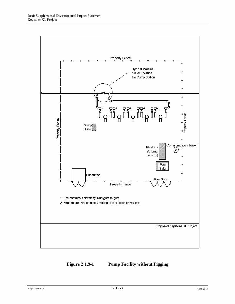
Draft Supplemental Environmental Impact Statement Keystone XL Project
Figure 2.1.9-1 Pump Facility without Pigging
Project Description 2.1-63 March 2013
Draft Supplemental Environmental Impact Statement Keystone XL Project
Keystone anticipates a peak workforce of approximately 5,000 to 6,000 construction personnel. These personnel would consist of Keystone employees, contractor employees, construction inspection staff, and environmental inspection staff. All workers would be trained and certified for their specific field of work (e.g., welders would be qualified as required by 49 CFR 195.222 and PHMSA Special Condition 18).
Keystone, through its construction contractors and subcontractors, would attempt to hire temporary construction staff from the local population. Assuming that qualified personnel are available, approximately 10 to 15 percent (50 to 100 people per spread) could be hired from the local workforce for each spread, although this may not be possible in rural areas. This may not be possible in more rural areas and or areas with low unemployment.
Cross-country pipeline construction would typically proceed at a pace of approximately 20 constructed miles per calendar month per spread. Construction would occur in the following approximate sequence:
• Two to three weeks (14 to 21 calendar days) of work on the ROW prior to the start of production welding. Activities would include clearing, grading, stringing, and ditching.
• Production welding at an average rate of 1.25 miles of pipe welded per working day over a 6day work week (over 7 calendar days), resulting in completion of an average of about 7.5 miles of pipeline per week.
• Seven weeks (49 calendar days) of additional work after completion of production welding. Activities would include nondestructive testing, field joint coating, pipe installation, tie-ins, backfill, ROW clean-up, hydrostatic testing, reseeding, and other ROW reclamation work.
Those time periods and rates of progress were used as the basis for determining the duration of construction activities on the ROW presented in Table 2.1-18 for various spread lengths. Construction in areas with greater congestion or higher population, in industrial areas, or in areas requiring other special construction procedures could result in a slower rate of progress. In addition, approximately 1 month would be required for contractor mobilization before the work is started and 1 month would be required for contractor demobilization after the work is finished.
2.1.10.2 Environmental Inspection Keystone would use environmental inspectors on each construction spread. The environmental inspectors would review the proposed Project activities daily for compliance with state, federal, and local regulatory requirements and would have the authority to stop specific tasks as approved by the chief inspector. The inspectors would also be able to order corrective action in the event that construction activities violate the provisions of the CMRP, landowner requirements, or any applicable permit requirements.
2.1.11 Operations and Maintenance The proposed Project would be operated, maintained, monitored, and inspected in accordance with 49 CFR 194 and 195 and other applicable federal and state regulations. Keystone has also agreed to incorporate 57 PHMSA Project-specific special conditions that address proposed Project operation, inspection, and monitoring (see Appendix B, PHMSA 57 Special Conditions). The operational requirements of 49 CFR 195 and the PHMSA Project-specific Special Conditions related to operation of the proposed Project (Appendix B, PHMSA 57 Special
Project Description 2.1-64 March 2013
Draft Supplemental Environmental Impact Statement Keystone XL Project
Conditions) would be included in the proposed Project operations, maintenance, and emergencies manual that would be required by 49 CFR 195.402, and they would also be incorporated into Keystone’s existing Operations Control Center (OCC) in Calgary, Canada. The remainder of this section addresses normal operation and routine maintenance and abnormal operations.
2.1.11.1 Normal Operations and Routine Maintenance Keystone would prepare the manuals and written procedures for conducting normal operations, maintenance, inspection, and monitoring activities as required by the PHMSA regulations, particularly as required by 49 CFR 195.402 and in the applicable PHMSA Project-specific special conditions (see Appendix B, PHMSA 57 Special Conditions). This would include development and implementation of an annual Pipeline Maintenance Program to ensure the integrity of the pipeline. The Pipeline Maintenance Program would include valve maintenance, periodic inline inspections, and CP readings to ensure facilities are reliable and in service. Data collected in each year of the program would be incorporated into the decision-making process for the development of the following year’s program.
The proposed Project OCC would be manned by experienced and highly trained personnel 24 hours per day, every day of the year in Calgary. In addition, a fully redundant backup OCC would be constructed, operated, and maintained, also in Canada. Primary and backup communications systems would provide real-time information from the pump stations to field personnel. The control center would have highly sophisticated pipeline monitoring systems including a leak detection system capable of identifying abnormal conditions and initiating visual and audible alarms. Automatic shut-down systems would be initiated if a valve starts to shut and all pumps upstream would turn off automatically. All other pipeline situations would require human response.
The proposed Project would include a supervisory control and data acquisition (SCADA) system to constantly monitor the pipeline system. The SCADA system would be installed and operated in accordance with the requirements of 49 CFR 195 and PHMSA Project-specific special conditions 24 through 31 (see Appendix B, PHMSA 57 Special Conditions). SCADA facilities would be located in the OCC and along the pipeline system, and all pump stations and delivery facilities would have communication software that sends data back to the OCC. The pipeline SCADA system would allow the OCC to remotely read IMLV positions, tank levels, and delivery flow and total volume. The OCC personnel would also be able to start and stop pump stations and open and close MLVs. SCADA systems are further discussed in Sections 2.1.11.1, Normal Operations and Routine Maintenance, and 4.13, Potential Releases.
The pipeline ROW would be inspected via aerial and ground surveillance to provide prompt identification of possible encroachments or nearby construction activities, ROW erosion, exposed pipe, or any other conditions that could result in damage to the pipeline. The aerial surveillance of the pipeline ROW would be carried out at least 26 times per year at intervals not to exceed 3 weeks as required by 49 CFR 195.412. Landowners would be encouraged to report any pipeline integrity concerns to Keystone or to PHMSA. IMLVs and MLVs at pump stations would also be inspected. As required by 49 CFR 195.420(b), they would be inspected at intervals not to exceed 7.5 months, but at least twice each calendar year.
Project Description 2.1-65 March 2013
Draft Supplemental Environmental Impact Statement Keystone XL Project
PHMSA regulations at 49 CFR 195.450 and Special Condition 14 require that pipeline operators identify areas along the proposed pipeline corridor that would be considered HCAs. While some of these areas need to be defined through sophisticated risk modeling, in general they are specific locales where an accidental spill from a hazardous liquid pipeline could produce significant adverse consequences as described in 49 CFR 195.450.
HCAs include navigable waterways, high population areas, and unusually sensitive areas. Keystone would need to identify the HCAs along the proposed route. Population changes along the route would be monitored throughout pipeline operation and any additional HCAs identified as necessary. Keystone would conduct a pipeline integrity management program in HCAs as required by 49 CFR 195.452 (Pipeline Integrity Management in HCAs).
All maintenance work would be performed in accordance with PHMSA requirements, the applicable PHMSA Special Conditions, and the stipulations in environmental permits issued for the proposed Project. Woody vegetation along the permanent easement would be cleared periodically in order to maintain accessibility for pipeline integrity surveys. Mechanical mowing or cutting would be carried out from time to time as needed along the permanent easement for normal vegetation maintenance. Cultivated crops would be allowed to grow in the permanent easement, but trees would be removed from the permanent ROW in all areas. In areas constructed using the HDD method, trees would be cleared as required on a site specific basis.
Permanent erosion control devices would be monitored to identify any areas requiring repair. The remainder of the ROW would be monitored to identify areas where additional erosion control devices would be necessary to prevent future degradation. The ROW would be monitored to identify any areas where soil productivity has been degraded as a result of pipeline construction. In these areas, reclamation measures would be implemented to rectify the problems.
Operation and maintenance of the proposed pipeline system would typically be accomplished by Keystone personnel. The permanent operational pipeline workforce would comprise about 50 employees strategically located along the length of the pipeline in the United States: 35 Keystone employees plus 15 contractual workers.
2.1.11.2 Abnormal Operations Keystone would implement Abnormal Operating Procedures in accordance with 49 CFR Section 195.402(d). Those procedures would be developed and documented in a manual as required by 49 CFR 195.402. The manual would include procedures to provide safety when operating design limits have been exceeded. That would include investigating and correcting the cause of unintended closure of valves or shutdowns, increases or decreases in pressure or flow rate outside normal operating limits, loss of communications, operation of any safety device, and any other malfunction of a component, deviation from normal operation, or personnel error which could cause a hazard to persons or property. Procedures would also include checking variations from normal operation after abnormal operation has ended at sufficient critical locations in the system to accomplish the following:
• Assure continued integrity and safe operation;
• Identify variations from normal operation of pressure and flow equipment and controls;
• Notify responsible operator personnel when notice of an abnormal operation is received;
Project Description 2.1-66 March 2013
Draft Supplemental Environmental Impact Statement Keystone XL Project
• Review periodically the response of operator personnel to determine the effectiveness of the procedures controlling abnormal operation; and
• Take corrective action where deficiencies are found. The operations manager on duty would be responsible for executing abnormal operating procedures in the event of any unusual situation.
Pipeline Integrity, Supervisory Control and Data Acquisition, and Leak Detection The following overlapping and redundant integrity systems and measures would be incorporated into the proposed Project:
• Quality Assurance program for pipe manufacture and pipe coating;
• FBE coating;
• CP;
• Non-destructive testing of 100 percent of the girth welds;
• Hydrostatic testing;
• Periodic internal cleaning and high-resolution in-line inspection;
• Depth of cover exceeding federal standards;
• Periodic aerial surveillance;
• Public awareness program;
• SCADA system; and
• An OCC with complete redundant backup, providing monitoring of the pipeline every 5 seconds, 24 hours per day, every day of the year.
SCADA facilities would be used to remotely monitor and control the pipeline system. This would include a redundant fully functional backup system available for service at all times. Automatic features would be installed as integral components within the SCADA system to ensure operation within prescribed pressure limits. Additional automatic features would be installed at the local pump station level and would provide pipeline pressure protection in the event communications with the SCADA host are interrupted. Software associated with the SCADA monitoring system and volumetric balancing would be used to assist in leak detection during pipeline operations. If pressure indications change, the pipeline controller would immediately evaluate the situation. If a leak is suspected, the ERP would be initiated, as described below. If there is a pipeline segment shutdown due to a suspected leak, operation of the affected segment would not be resumed until the cause of the alarm (e.g., false alarm by instrumentation or a leak) is identified and repaired. In the case of a reportable leak, PHMSA approval would be required to resume operation of the affected segment. A number of complementary leak detection methods and systems would be available within the OCC and would be linked to the SCADA system.
Remote monitoring would consist primarily of monitoring pressure and flow data received from pump stations and valve sites that would be fed back to the OCC by the SCADA system. Software-based volume balance systems would monitor receipt and delivery volumes and would
Project Description 2.1-67 March 2013
Draft Supplemental Environmental Impact Statement Keystone XL Project
detect leaks down to approximately 5 percent of pipeline flow rate. Computational Pipeline Monitoring or model-based leak detection systems would separate the pipeline system into smaller segments and would monitor each segment on a mass balance basis. These systems would detect leaks down to a level of approximately 1.5 to 2 percent of the pipeline flow rate. Computer-based, non-real time, accumulated gain/loss volume trending would assist in identifying low rate or seepage leaks below the 1.5 to 2 percent by volume detection thresholds. If any of the software-based leak detection methods indicates that a predetermined loss threshold has been exceeded, an alarm would be sent through SCADA and the Controller would take corrective action. The SCADA system would continuously poll all data on the pipeline at an interval of approximately 5 seconds.
If an accidental leak were to occur, the operator would shut down operating pumping units and close the isolation valves. Once shutdown activities are initiated, it would take approximately 9 minutes to complete the emergency shut-down procedure (shut down operating pumping units) and an additional 3 minutes to close the isolation valves.
In addition to the SCADA and complementary leak detection systems, direct observation methods, including aerial patrols, ground patrols and public and landowner awareness programs, would be implemented to encourage and facilitate the reporting of suspected leaks and events that could suggest a threat to the integrity of the pipeline.
Keystone has committed to keep abreast of the latest developments in external leak detection technologies (above and beyond those already proposed to be implemented, as described) that could be installed along the pipeline at sensitive locations. In Nebraska, Keystone would report to, and discuss with, the Nebraska Department of Environmental Quality (NDEQ) the status of innovation in such pipeline leak detection equipment and the methods on or before January 1, 2014, and at such additional times thereafter until 2024 as the NDEQ shall specifically request, but in no case more frequently than once every three years. A similar leak detection requirement exists in the SDPUC certificate. There is no comparable requirement in Montana.
Emergency Response Procedures PHMSA requires that pipeline operators prepare and abide by both the PSRP and the ERP for responding to emergencies on their systems. 49 CFR 194 requires that pipeline operators have response plans that ensure resources are available to remove, mitigate, or prevent a discharge from an oil pipeline that could cause substantial or significant harm to the environment, including a worst case discharge. As stated in 49 CFR 194.7(a), a pipeline operator “may not handle, store, or transport oil unless the operator has submitted a response plan meeting requirements of this part,” and as stated in 49 CFR 194.7(b), operators must also operate onshore pipeline facilities in accordance with the approved response plan. In addition, 49 CFR 194.107 requires that the response plan include “procedures and a list of resources for responding, to the maximum extent practicable, to a worst case discharge, and to a substantial threat of such a discharge.”
Keystone would determine the optimal location of spill response equipment, taking into account response times to sensitive areas and receptors. These spill response locations would be reflected in the ERP that would be submitted to PHMSA for review and approval.
Keystone would submit a PSRP to PHMSA prior to initiation of proposed Project operations in accordance with the requirements of 49 CFR 194. The PSRP would describe how spills would be
Project Description 2.1-68 March 2013
Draft Supplemental Environmental Impact Statement Keystone XL Project
responded to in the event of a release from the proposed Project resulting from any cause (e.g., corrosion, third-party damage, natural hazards, materials defects, hydraulic surge). The plan would address the maximum spill scenario and the procedures that would be in place to deal with the maximum spill. The PSRP requires PHMSA review and approval; however, there is a 2-year grace period under which operations can proceed, thus allowing PHMSA time to review the document in light of as-built Project conditions and to require incorporation of any needed changes to ensure system safety prior to PHMSA approval.
As required by 49 CFR 195.40, Keystone would also prepare and follow a manual of written procedures for conducting normal operations and maintenance activities and handling abnormal operations and emergencies. This manual would be reviewed by PHMSA at intervals not exceeding 15 months, but at least once each calendar year, and appropriate changes would be made as necessary to ensure that the manual is effective. This manual would be prepared before initial operations of the proposed Project and appropriate sections would be kept at locations where operations and maintenance activities are conducted. The emergency section of this operations and maintenance plan would be prepared by Keystone in a separate document that Keystone refers to as the ERP.
While USEPA has authority under the Clean Water Act and Oil Pollution Act of 1990 with respect to regulation of onshore non-transportation related facilities and USEPA requires the development and submittal of a Facility Response Plan for any such facility, it appears that none of the facilities or activities associated with the proposed Project would be subject to the USEPA regulatory authority, as discussed below. Keystone would therefore be required to develop a PSRP for review and approval by PHMSA and an ERP for review by PHMSA for the proposed Project. PHMSA may request USEPA and U.S. Coast Guard consultation on the response elements of the PSRP. Keystone would share on its own volition portions of the PSRP with community emergency responders along the proposed pipeline corridor to ensure an appropriate level of collaborative emergency response planning. However, based on a PHMSA advisory bulletin issued on November 3, 2010, Keystone would be required to share the ERP with local emergency responders in relevant jurisdictions along the proposed Project corridor. The bulletin notes that operators of gas and hazardous liquid pipeline facilities must make their pipeline ERPs available to local emergency response officials.
While the draft PSRP and the draft ERP for the proposed Project are not yet available, Keystone prepared similar plans for the existing Keystone Pipeline Project. These plans for the proposed Project would have the same general approach as those plans but would have many specific differences, such as the names and contact information for responders along the proposed Project route.
There have been concerns raised about the possibility of a spill comparable to the Kalamazoo spill in Marshall, Michigan, on the proposed Project. There are a number of reasons, discussed below, that this is not anticipated. Nevertheless, Keystone would be prepared to respond to a spill of a similar magnitude and extent of the Marshall, Michigan, incident. Further, the lessons learned from the incident would be incorporated into industry recommendations and guidance.
Keystone would incorporate lessons learned throughout the life of the project in the following ways:
• PHMSA Advisory Bulletins: These items are incorporated in the applicable phase of the Project (e.g., design, construction, or operations) through modification of the Project’s
Project Description 2.1-69 March 2013
Draft Supplemental Environmental Impact Statement Keystone XL Project
specific design requirements or construction scope of work, or incorporation into Keystone’s Integrity Management Plan or Operations Manual.
• NTSB Accident Reports: Keystone reviews these draft and final reports for pertinent findings and incorporates them into design basis or procedures, if applicable.
• Industry Publications: Keystone has representation on all major Standards and Association Committees and incorporates the appropriate feedback into specification revisions for its pipeline assets, including Keystone, as appropriate through the Company’s Engineering Standards group.
• PHMSA Special Conditions 25c and 43 are examples of where NTSB accident reports and PHMSA advisory bulletins are incorporated into the Project.
Environmentally, the lessons learned from the Marshall, Michigan, dilbit spill behavior and related response implications include:
• The total volume of dilbit released to a river will not float on water indefinitely and dilbit characteristics, water temperature, and particulate load in the water could result in much of the oil being submerged in the water column.
• Submerged oil can be suspended in the water column, suspended just above the river bed, or intermixed with sediment and trapped in the river bed and shoreline.
• Submerged oil in a flowing water environment introduces additional recovery challenges for responders.
• Response action planning and response equipment to contain and recover submerged oil should be considered.
• Dilbit intermixed with sediment and trapped in the river bed and shoreline may result in a persistent source of oil and dissolved components such as benzene, polycyclic aromatic hydrocarbons, and heavy metals that could be slowly released back to the water column and transported down current.
• Dilbit intermixed with sediment can persist for years. The pipeline involved in the Marshall, Michigan, incident was constructed in the 1950s. Pipeline standards have evolved and new technologies have resulted in improvements in pipeline safety performance. Pipelines are now constructed with higher quality steel that is stronger and has better fracture resistant properties, helps reduce the impacts of external forces, such as flooding and excavation damage. Improvements in external pipeline coatings, the use of cathodic protection, and mandatory in-line inspection tools have resulted in significant reductions in corrosion-related incidents. TransCanada has not experienced a corrosion-related failure on any of its pipelines that utilize modern FBE coatings. Federal pipeline regulations have evolved over time and pipeline operators are now required to actively manage their pipelines to reduce the possibility of incidents. Operating procedures and leak detection capabilities have improved to more quickly detect leaks, thereby minimizing the amount of crude oil released and reducing subsequent impacts.
Project Description 2.1-70 March 2013
Draft Supplemental Environmental Impact Statement Keystone XL Project
Keystone has reviewed the NTSB 2012 Marshall, Michigan Accident Report including the conditions that led to operational failures on the pipeline that resulted in the spill. Keystone would include lessons learned from this spill, including:
• Get big quick: timeliness of a tactical response to an oil spill into water is imperative. While Keystone has stated that it already uses this philosophy, the Kalamazoo spill reinforced this need to respond with as many resources as possible as quickly as possible. To that end, Keystone would strategically store equipment and employ personnel and contractors along the length of the pipeline to ensure a maximum of a 6-hour response time.
• Pre-qualify a large contractor network: Contractors would be used to supplement any response Keystone would make to an oil spill. By ensuring a large pool of trained/skilled contractors along the length of the pipeline have been pre-qualified and contracted with Keystone, the response time would be minimized and resources (equipment and personnel) available are maximized.
• Emergency response planning details need to include source containment: source containment plans including strategies and tactics would be included in the overarching ERP.
• Equipment resources required for sunken and submerged oil: Keystone would further identify equipment resources required to respond to sunken and submerged oil and ensure personnel are appropriately trained on its use. A primary strategy for oil spill response would still be to contain and recover as much oil as possible as quickly as possible to prevent oil from weathering and therefore potentially becoming submerged and sinking. In addition, Keystone already owns and practices the use of containment devices that will prevent downstream migration of submerged and sunken oil such as dams. This type of equipment would be further identified and procured for the proposed Project.
In addition, Keystone would implement its own company standards and the 57 Special Conditions, which include operational requirements. The proposed Project would be constructed to standards that exceed current federal regulatory requirements. In addition to company-specific standards that exceed current federal pipeline safety standards (e.g., typical burial depth of 4 feet of cover rather than the standard 3 feet depth of cover), Keystone has agreed to implement an additional 57 Special Conditions identified in the Final EIS. The Final EIS stated that the implementation of these additional conditions would result in a level of safety equal to or exceeding the current levels as required by federal regulations.
Pipeline conditions along the proposed Project would be continuously monitored 24 hours a day, 7 days a week. The proposed Project would have over 16,000 sensors along its length and multiple, overlapping state-of-the-art leak detection systems.
While flood conditions are not a leading cause of pipeline failures, they can be a threat to pipeline integrity in certain locations. Under federal regulations (49 CFR Part 195), Keystone’s Integrity Management Program is required to monitor and reduce risks from various threats, such as outside forces due to flooding. Keystone has evaluated stream crossings to identify those locations where stream scour could affect pipeline integrity. Where there is potential for significant stream scour, Keystone has increased burial depth so stream scour does not pose a threat to pipeline integrity. Additionally, under Special Condition 19, Keystone is required to maintain depth of cover for the life of the Project.
Project Description 2.1-71 March 2013
Draft Supplemental Environmental Impact Statement Keystone XL Project
The proposed Project is a modern pipeline built to higher standards than pipelines built in the 1950s. Further, there are a number of operational requirements for the Keystone XL Pipeline that exceed current regulations; consequently, the pipeline is expected to operate at a higher level of safety than other pipelines currently in operation. Finally, Keystone has stated its commitment to the prevention of incidents including using lessons learned from the entire industry to continue to improve its pipeline safety programs.
The publically available portion of the Keystone Oil Pipeline System ERP is included as Appendix I, SPCC and ERP (parts of the ERP and the PSRP are considered confidential by PHMSA and the U.S. Department of Homeland Security). As described in Section 4.13, Potential Releases, the existing Keystone Oil Pipeline Project documents would be used as templates for the plans for the proposed Project. Project-specific information would be inserted into the plans as it becomes available. In addition, response equipment would be procured and strategically positioned along the route, staff would be trained in spill response and the Incident Command System, and emergency services and public officials would be educated on all aspects of the proposed Project and what their roles would be if an accidental leak were to occur. If a spill were to occur, Keystone and its contractors would be responsible for recovery and cleanup. PHMSA would require a certification from Keystone that necessary emergency response equipment is available in the event of an unplanned spill prior to providing Keystone with an authorization to begin operating the proposed Project.
The specific locations of Keystone’s emergency responders and equipment would be determined upon conclusion of the pipeline detailed design and described in the PSRP and ERP. Company emergency responders would be placed consistent with industry practice and with applicable regulations, including 49 CFR Parts 194 and 195.The response time to transfer additional resources to a potential leak site would follow an escalating tier system, with initial emergency responders capable of reaching all locations within 6 hours in the event of a spill for high volume areas; the spill response for all other areas is 12 hours. Typically, emergency responders would be based in closer proximity to the following areas:
• Commercially navigable waterways and other water crossings;
• Populated and urbanized areas; and
• Unusually sensitive areas, including drinking water locations, ecological, historical, and archaeological resources.
Keystone contacted first responders along the mainline route as part of its stakeholder outreach program in advance of going into service. On an annual basis, at minimum, awareness information materials are delivered to local level emergency service agencies including fire, police, 911, county emergency managers, and Tribal agencies along the Keystone route. This includes operator information such as pipeline location, product awareness, how to recognize the signs of a leak, how to contact Keystone, and guidelines on how to respond. Keystone regularly partners with the communities in which it operates and supports emergency responder development. This has included donations of fire truck rigging, rope rescue equipment, trailers, and air bag kits. Additionally, Keystone has jointly planned with emergency responders to store equipment in strategic locations to facilitate an effective response. In select cases, Keystone would collaborate with dedicated hazmat teams to determine additional emergency response tactics they may undertake. Additional details can be found in Section 4.13, Potential Releases.
Project Description 2.1-72 March 2013
Draft Supplemental Environmental Impact Statement Keystone XL Project
Types of emergency response equipment situated along the pipeline route would include pick-up trucks, one-ton trucks and vans; vacuum trucks; work and safety boats; containment boom; skimmers; pumps, hoses, fittings and valves; generators and extension cords; air compressors; floodlights; communications equipment including cell phones, two way radios, and satellite phones; containment tanks and rubber bladders; expendable supplies including absorbent booms and pads; assorted hand and power tools including shovels, manure forks, sledge hammers, rakes, hand saws, wire cutters, cable cutters, bolt cutters, pliers and chain saws; ropes, chains, screw anchors, clevis pins and other boom connection devices; personnel protective equipment including rubber gloves, chest and hip waders and airborne contaminant detection equipment; and wind socks, signage, air horns, flashlights, megaphones and fluorescent safety vests. Emergency response equipment would be maintained and tested in accordance with manufacturers recommendations. These materials would be stored in a trailer; the locations would be determined once the system design is complete and the analysis of risk finalized Additional equipment, including helicopters, fixed-wing aircraft, all-terrain vehicles, snowmobiles, backhoes, dump trucks, watercraft, bull dozers, and front-end loaders could also be accessed depending upon site-specific circumstances. Other types, numbers, and locations of equipment would be determined upon conclusion of the pipeline detailed design and the completion of the PSRP and the ERP for the proposed Project.
Several federal regulations define the notification requirements and response actions in the case of an accidental release, including the 40 CFR Part 300 (National Oil and Hazardous Substances Pollution Contingency Plan), the Clean Water Act, and Oil Pollution Act of1990.If an accidental spill occurs, Keystone would implement several procedures to mitigate damage, including a line shut down. Other procedures would include immediate dispatch of a first responder to verify the release and secure the site. Simultaneously, an Incident Command System would be implemented and internal and external notifications would take place. The National Response Center would be notified if the spill meets one of the prescribed criteria. Keystone and the National Response Center would also notify other regional and local emergency response agencies as quickly as possible. All of this information would be included in the ERP for the proposed Project.
In the event of a suspected leak or if a spill is reported to the OCC, after verification there would be an emergency pipeline shutdown. Details on the type of verification to be used, what conditions get reported, and what magnitude release would trigger a shutdown are provided in Appendix I, SPCC and ERP. This would involve stopping all operating pumping units at all pump stations. The on-call response designate would respond to and verify an incident. Once the OCC notifies the individual and an assessment of the probability and risk is established, field personnel could elect to dispatch other resources as soon as practical. Response efforts would first be directed to preventing or limiting any further contamination of the waterway, once any concerns with respect to health and safety of the responders have been addressed.
A review of PHMSA data related to pipeline accidents indicates that most explosions occur in pipelines that are transporting highly flammable, highly volatile hydrocarbons such as natural gas, liquid propane gas, propane, gasoline, naphtha, or similar products. For an ignition to occur, produced vapors must be above the lower flammability limit of the vapor and sufficient oxygen and an ignition source present. Within a pipeline, oxygen conditions are too low and an ignition source is not present, so an explosion within the pipeline is unlikely.
Project Description 2.1-73 March 2013
Draft Supplemental Environmental Impact Statement Keystone XL Project
Oil spills on the ground surface and some releases below grade potentially could ignite. PHMSA data for onshore oil and hazardous material pipelines indicate that only 6 of 2,706 incidents (0.2 percent) that occurred from 1990 through 2009 were attributed to “fire/explosion as a primary cause.” Six out of 3,033 incidents were reported as due to the referenced cause. Two out of 1,360 crude oil incidents were reported as due to the reference cause.
A search of the internet for reports of crude oil pipeline explosions suggests that 1) there are very few if any explosions in crude oil pipeline operation that were the result of a failure of the pipeline as a primary cause, and 2) the very few that have occurred are attributable to explosions in ancillary facilities or errors in operations unassociated with crude oil transportation. For example, the recent explosion and fire in the crude oil pipeline/storage tank area in Dalian, China, occurred as a result of an improper desulfurization operation; the primary cause was not the transport of crude oil in the pipeline.
An accidental crude oil spill from the pipeline or at a pump station would likely result in some hydrocarbon vapors, but they would not be in confined spaces and therefore would be unlikely to explode. A fire associated with a release from a crude oil pipeline is relatively rare. In the event of a fire, local emergency responders would execute the roles listed above and more specifically in the PSRP and the ERP, and firefighters would take actions to prevent the crude oil fire from spreading to residential areas.
Remediation Corrective remedial actions would be dictated by federal, state, and local regulations and enforced by the USEPA, Office of Pipeline Safety, and appropriate state and/or local agencies. Required remedial actions may be large or small, dependent upon a number of factors including state mandated remedial cleanup levels, potential effects to sensitive receptors, the volume and extent of the contamination, whether or not there is a violation of water quality standards, and the magnitude of adverse impacts caused by remedial activities. A large remediation action may include the excavation and removal of contaminated soil or could involve allowing the contaminated soil to recover through natural attenuation or environmental fate processes such as evaporation and biodegradation.
If, during construction, tanks or contamination are found, they would be managed according to federal, state, and/or local regulations. Further, Keystone would make individuals available who are trained in identifying and disposing of hazardous materials during construction.
If there is an accidental release from the proposed Project, Keystone would implement the remedial measures necessary to meet the federal, state, and local standards that are designed to ensure protection of human health and environmental quality. Additional information on remediation is presented in Section 4.13, Potential Releases.
2.1.12 Connected Actions There are three actions that are separate from the proposed Project that are not part of the Presidential Permit application submitted by Keystone, but are being reviewed as connected
Project Description 2.1-74 March 2013
Draft Supplemental Environmental Impact Statement Keystone XL Project
actions6
6 Additional relevant information related to connected actions is pending and will be included in this review as part of the Final Supplemental EIS.
pursuant to NEPA. The three connected actions are the Bakken Marketlink Project, the Big Bend to Witten 230-kilovolt (kV) electric transmission line, and electric distribution lines and substations associated with the proposed pump stations.
Preliminary information on the design, construction, and operation of these projects is presented below. Although the permit applications for these projects would be reviewed and acted on by other agencies, the potential impacts of these projects have been analyzed in the Supplemental EIS based on currently available information and are addressed within each resource assessed in Chapter 4, Environmental Consequences. However, in some cases only limited information was available on the design, construction, and operation of the projects. The reviews of permit applications by other agencies would include more detailed environmental reviews of the connected actions.
2.1.12.1 Bakken Marketlink Project Keystone Marketlink, LLC, a wholly owned subsidiary of TransCanada Pipelines Limited, is proposing to construct and operate the Bakken Marketlink Project. It would include construction and operation of facilities within the boundaries of the proposed Keystone XL Cushing tank farm. This location is adjacent to the Cushing Oil Terminal, a key pipeline transportation and crude oil storage hub with over 50 million barrels of storage capacity. Crude oil in the Bakken Marketlink storage tanks at the Cushing tank farm would either be pumped to the Keystone XL pipeline or to other pipelines and tank farms near Cushing. The Cushing tank farm would be near many pipelines, storage facilities, and refineries; the Cushing area is a major crude oil marketing, refining, and pipeline hub that provides shippers with many delivery options and market access. The project would include construction of facilities to provide crude oil transportation service from near Baker, Montana, to the Keystone Cushing Expansion in Kansas. Keystone Marketlink, LLC obtained commitments for transport of approximately 65,000 barrels per day (bpd) of crude oil through the Marketlink Project. The Bakken Marketlink Project could deliver up to 100,000 bpd to the proposed Project depending on ultimate shipper commitments.
The project would consist of piping, booster pumps, meter manifolds, and one 250,000-barrel tank that would be used to accumulate crude from connecting third-party pipelines and terminals and a 100,000-barrel tank that would be used for operational purposes (see Figure 2.1.12-1). Tanks at both locations will be external floating roof tanks. At Cushing there will be crude oil booster pumps located at the facility for transfer of the crude oil from the pipeline to the crude oil storage tanks. All booster pumps are electrically driven. Preliminary design engineering indicates that no combustion equipment (e.g., emergency generator engines) or other add-on control devices (e.g., emergency flares or vapor recovery units) would be constructed at the facility. The facilities would also include a proposed pipeline that would be approximately 5 miles in length, originating south of pump station 14 at a third party tank farm in Fallon County, and extending to the Keystone Bakken Terminal. TransCanada Pipelines Limited Bakken held introductory meetings with State and local permitting agencies in 2011, and also held a meeting for potentially affected landowners along the route. Adjustments in the alignment are possible as a result of civil surveys, further landowner discussions, and permitting. The proposed in service date for the Bakken Marketlink Project is projected to be the first or second quarter of 2015.
Project Description 2.1-75 March 2013
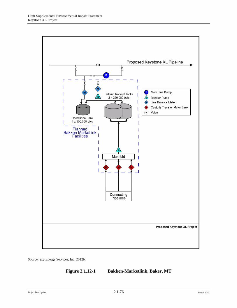
Draft Supplemental Environmental Impact Statement Keystone XL Project
Source: exp Energy Services, Inc. 2012b.
Figure 2.1.12-1 Bakken-Marketlink, Baker, MT
Project Description 2.1-76 March 2013
Draft Supplemental Environmental Impact Statement Keystone XL Project
2.1.12.2 Big Bend to Witten 230-kV Transmission Line After receipt of information on the power requirements for the proposed pump stations in South Dakota, Western Area Power Administration (Western) conducted a joint system engineering study to determine system reliability under the proposed loads at full Project electrical energy consumption. Engineering studies determined that a 230-kV transmission line would be required to support voltage requirements for pump stations 20 and 21 in the Witten area when the proposed Project is operating at maximum capacity (Figure 2.1.12-2). To address this requirement, Western proposes to replace the existing Big Bend-Fort Thompson No. 2 230kV Transmission Line Turning Structure located on the south side of the dam, construct a new double circuit 230 kV transmission line for approximately 1 mile south west of the dam, and construct a new Lower Brule Substation. These actions are part of the larger Big Bend to Witten 230 kV Transmission Line Project.
Basin Electric Power Cooperative (BEPC) is proposing to construct and operate a new single circuit 230-kilovolt (kV) transmission line in south-central South Dakota that would extend from a new substation (Lower Brule Substation) south of the Big Bend Dam on Lake Sharpe approximately 74 miles south-southwest to the existing Witten Substation located south of U.S. Highway 18.The approximate 76-mile Big Bend to Witten 230-kV Transmission Project (Project) consists of the aforementioned elements. The new Big Bend to Witten 230 kV transmission line would be built, owned, and operated by BEPC. The Witten Substation would also need to be expanded to accommodate the new switching equipment associated with the Big Bend to Witten 230-kV transmission line (see Appendix J, Basin Electric Big Bend to Witten 230-kV Transmission Project Routing Report)
The Project is located within Lyman and Tripp counties in south-central South Dakota. Approximately 6 miles of the single-circuit transmission line and all of the double-circuit transmission line, as well as Western’s Lower Brule Substation, would be constructed on the Lower Brule Indian Reservation (see Figure 2.1.12-2). The proposed Lower Brule Substation would occupy approximately 16 acres of land. The existing Witten Substation would be expanded immediately to the northeast to accommodate the new 230-kV connection. The new part of the substation would have a separate access road and would be separated by a fence from the existing Witten Substation.
BEPC has applied to the U.S. Department of Agriculture’s Rural Utility Service (RUS) for financing and proposes to construct and operate the Project to meet existing and future electric power requirements in south central South Dakota. BEPC would interconnect the new transmission line to the existing Western transmission system. Under RUS regulations for implementation of NEPA, an Environmental Assessment with scoping is being prepared to assess potential impacts of the proposed action on the human and natural environment. RUS is responsible for NEPA compliance and related statutes for the proposed Project. Since the Project would be constructed partly on the Lower Brule Indian Reservation, other cooperating agencies may be identified. RUS is the lead agency and Western is participating as the cooperating agency. Figure 2.1.12-2 shows the proposed route and two alternative routes currently under consideration in the Environmental Assessment process.
The proposed Project would transfer power from Western’s transmission system near Big Bend Dam to Rosebud Electric Cooperative’s Witten Substation, near Witten, South Dakota. It is anticipated that some communication facility additions or enhancements may be necessary for
Project Description 2.1-77 March 2013
Draft Supplemental Environmental Impact Statement Keystone XL Project
the Project, including communication towers and buildings at the Lower Brule Substation, Witten Substation, and other intermediate sites.
The proposed transmission structures would be steel single-poles and would be designed to support three conductors and an overhead optical ground wire. Tangent structures would be directly embedded into the soil and angle and dead-end structures would be constructed using concrete foundations. No guy wires are proposed. The design criteria for the portion of the line between the Big Bend Dam and the Lower Brule Substation are expected to be similar.
The proposed transmission line would be constructed within a 125-foot-wide ROW. All substation and switchyard work, including the placement of concrete foundations, erecting support structures, construction of control buildings, and the installation of electrical equipment would take place within secured areas. The proposed substation site at Big Bend and the expansion area at Witten would be cleared and leveled. Aggregate would be spread throughout undeveloped areas within the substation sites. Topsoil would be segregated from underlying soils and redistributed on disturbed areas outside the substation security fences. Soil erosion would be minimized during construction using best management practices. Substation components would be hauled to the site on local highways and roads and off-loaded using cranes and similar equipment. Concrete and aggregate from local sources would be hauled to the site by truck.
The impacts of construction and operation of the transmission line alternatives are addressed in Chapter 4, Environmental Consequences. An additional and separate NEPA environmental review of the alternatives to the proposed transmission line would be conducted after the alternative routes are further defined. The design and environmental review of the proposed 230kV transmission line are on a different schedule than the pipeline system itself. Regional transmission system reliability concerns are not associated with the initial operation of the proposed pipeline pump stations, but only for future operation at the maximum throughput volume of 830,000 bpd.
2.1.12.3 Electrical Distribution Lines and Substations Multiple private power companies or cooperatives would construct distribution lines to deliver power to 20 pump stations located along the United States length of the pipeline. The private power companies providing the distribution lines are responsible for obtaining the necessary permits, approvals, or authorizations from Federal, state or local governments. These distribution lines range in length from about 0.1-mile to 62 miles in length, average about13 miles long, and are estimated to extend about 377 miles, combined. The distribution lines to service pipeline pump stations would range in capacity from 69 kV to 240 kV, but the majority would have a capacity of 115 kV. Table 2.1-19 lists the electrical power supply requirements for the pump stations and Figures 2.1.1-3 through 2.1.1-5 depict the locations of the distribution lines. Most of the proposed new electrical distribution lines to service pump stations would be 115-kV lines strung a single-pole and/or H-frame wood poles. The poles would typically be about 60- to 80feet-high with wire span distances of about 250 to 400 feet.
Project Description 2.1-78 March 2013
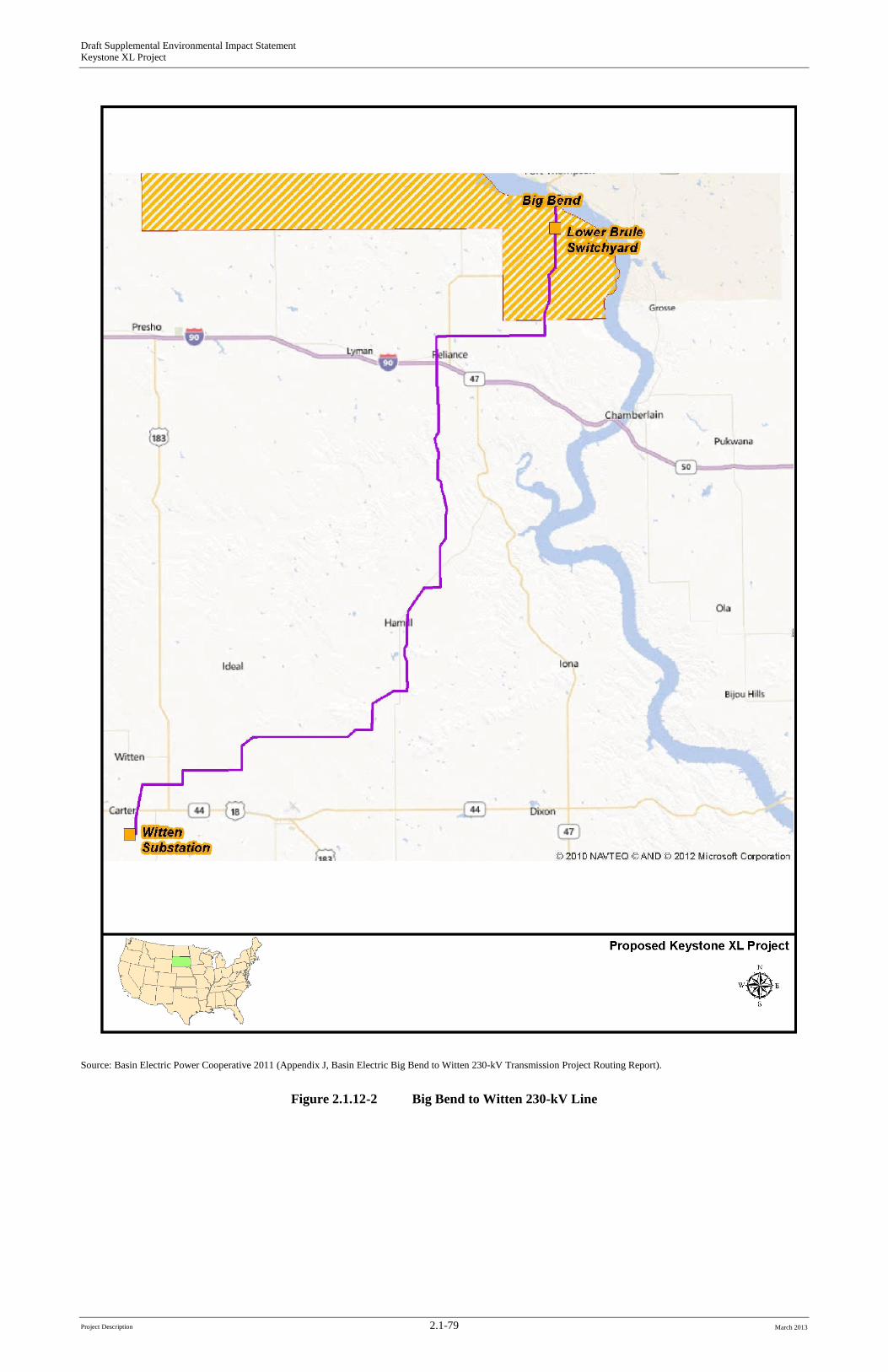
Draft Supplemental Environmental Impact Statement Keystone XL Project
Source: Basin Electric Power Cooperative 2011 (Appendix J, Basin Electric Big Bend to Witten 230-kV Transmission Project Routing Report).
Figure 2.1.12-2 Big Bend to Witten 230-kV Line
Project Description 2.1-79 March 2013

Draft Supplemental Environmental Impact Statement Keystone XL Project
-Page Intentionally Left Blank-
Project Description 2.1-80 March 2013
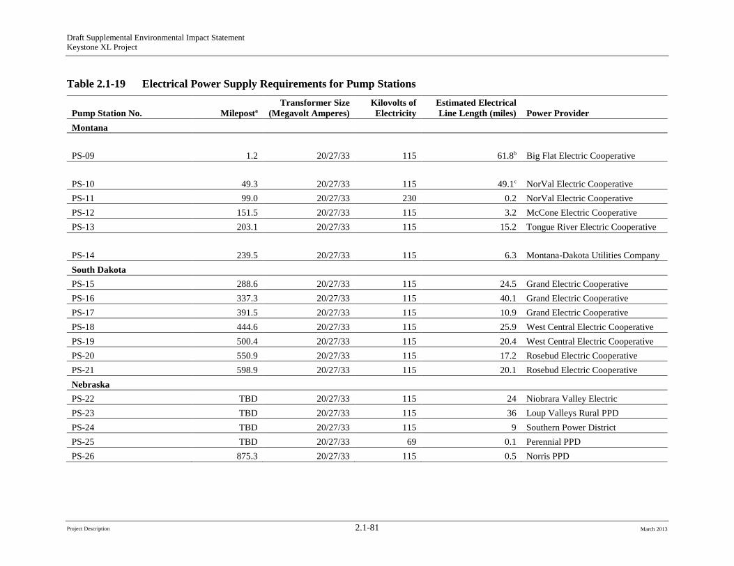
Project Description 2.1-81
Draft Supplemental Environmental Impact Statement Keystone XL Project
Table 2.1-19 Electrical Power Supply Requirements for Pump Stations
Pump Station No. Mileposta Transformer Size
(Megavolt Amperes) Kilovolts of Electricity
Estimated Electrical Line Length (miles) Power Provider
Montana
PS-09 1.2 20/27/33 115 61.8b Big Flat Electric Cooperative
PS-10 49.3 20/27/33 115 49.1c NorVal Electric Cooperative PS-11 99.0 20/27/33 230 0.2 NorVal Electric Cooperative PS-12 151.5 20/27/33 115 3.2 McCone Electric Cooperative PS-13 203.1 20/27/33 115 15.2 Tongue River Electric Cooperative
PS-14 239.5 20/27/33 115 6.3 Montana-Dakota Utilities Company South Dakota PS-15 288.6 20/27/33 115 24.5 Grand Electric Cooperative PS-16 337.3 20/27/33 115 40.1 Grand Electric Cooperative PS-17 391.5 20/27/33 115 10.9 Grand Electric Cooperative PS-18 444.6 20/27/33 115 25.9 West Central Electric Cooperative PS-19 500.4 20/27/33 115 20.4 West Central Electric Cooperative PS-20 550.9 20/27/33 115 17.2 Rosebud Electric Cooperative PS-21 598.9 20/27/33 115 20.1 Rosebud Electric Cooperative Nebraska PS-22 TBD 20/27/33 115 24 Niobrara Valley Electric PS-23 TBD 20/27/33 115 36 Loup Valleys Rural PPD PS-24 TBD 20/27/33 115 9 Southern Power District PS-25 TBD 20/27/33 69 0.1 Perennial PPD PS-26 875.3 20/27/33 115 0.5 Norris PPD
March 2013
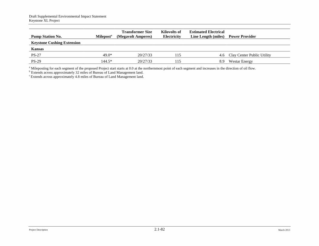
Draft Supplemental Environmental Impact Statement Keystone XL Project
Pump Station No. Mileposta Transformer Size
(Megavolt Amperes) Kilovolts of Electricity
Estimated Electrical Line Length (miles) Power Provider
Keystone Cushing Extension Kansas PS-27 49.0* 20/27/33 115 4.6 Clay Center Public Utility PS-29 144.5* 20/27/33 115 8.9 Westar Energy
a Mileposting for each segment of the proposed Project start starts at 0.0 at the northernmost point of each segment and increases in the direction of oil flow. b Extends across approximately 32 miles of Bureau of Land Management land. c Extends across approximately 4.8 miles of Bureau of Land Management land.
Project Description 2.1-82 March 2013
Draft Supplemental Environmental Impact Statement Keystone XL Project
To the extent practicable, Keystone would coordinate, and has been coordinating, with the local public power district to minimize potential impacts to landowners resulting from the construction of the new transmission lines to pump stations. These power providers would construct the necessary substations and transformers and would either use existing service lines or construct new service lines to deliver electrical power to the specified point of use. The electrical power providers would be responsible for obtaining the necessary permits, approvals, or authorizations from federal, state, and local governments, except in those instances in Montana, where new service lines less than 10 miles in length would be constructed. Under Montana regulations, these distribution lines are considered “associated facilities” connected with the overall pipeline system. Review and approval under Montana law of the associated facilities occurred as part of the review and approval of Keystone’s Major Facility Siting Act application.
In Montana and South Dakota, the following are Western’s actions directly related to commercial electrical service for the proposed Project pump stations:
• Bowdoin Substation, Phillips County, Montana: Pump Station 9 would be served by Big Flat Electric Cooperative (Big Flat). The interconnection point would be at a new Western Area Power Administration (Western) owned and operated substation named Bowdoin on its existing Fort Peck-Havre 161-kV line. The new substation would consist of a Western owned three breaker 230-kV ring bus and 115-kV capacitor banks and associated bays. It would also include two Big Flat owned power transformers, high and low side transformer interrupters, and a 115-kV line bay. Big Flat would construct approximately 55 miles of 115-kV transmission line that would connect the new Bowdoin Substation to the existing Math Substation which would directly serve Pump Station 9. Land acquisition for the new Bowdoin Substation would be by BLM withdrawal and would be completed by Keystone.
• Fort Peck Substation, McCone County, Montana: Western would expand its existing Fort Peck substation to serve Norval Electric Cooperative (Norval) who would distribute electrical service to Pump Station 10. The substation expansion would include the construction of a 115-kV breaker bay on the south side of the substation. Land acquisition for the substation expansion would be completed by Western.
• Coal Hill Substation, McCone County, Montana: Western would construct a new 230-kV switching station directly adjacent to Pump Station 11. The new Western owned switchyard would be named Coal Hill, and would be configured in a three breaker ring configuration, with a Norval owned 230/6.9-kV power transformer. Norval would distribute electrical service to Pump Station 11. Keystone would acquire the necessary land and transfer ownership to Western.
• Circle Substation, McCone County, Montana: Western previously converted an existing 115-kV single substation configuration to a main-and-transfer substation configuration to accommodate unplanned load growth unrelated to the proposed Project. At the same time, Western replaced a 115/34.5-kV transformer and installed two 8-MVAR shunt capacitor banks. Western’s unrelated substation expansion would accommodate an interconnection point in the 115-kV bus for McCone Electric Cooperative to serve the Pump Station 12 load. No additional land acquisition would be required.
• O’Fallon Substation, Prairie County, Montana: Western would expand their existing O’Fallon Substation and construct a new 115-kV breaker bay to accommodate Tongue River
Project Description 2.1-83 March 2013
Draft Supplemental Environmental Impact Statement Keystone XL Project
Electrical Cooperative’s service to Pump Station 13. Land acquisition for the substation expansion would be completed by Western.
• Philip Substation, Haakon County, South Dakota: Western’s Phillip Substation would require an expansion with a new 115-kV bay addition and two 20 MVAR capacitor banks. The expansion would accommodate West Central Electric Cooperative’s service to Pump Station 18. A slight yard expansion onto property already owned by Western accommodated a new 230-kV breaker addition unrelated to the proposed Project, and provided enough room to install the new Central Electric Cooperatives facilities. No additional land acquisition would be required.
• Midland Substation, Haakon County, South Dakota: Western’s existing Midland Substation would require expansion for a new 115-kV bay to accommodate West Central Electric Cooperatives service to Pump Station19. Construction of this interconnection would require a small yard expansion to the east. Land acquisition for the substation expansion would be completed by Western.
• Gregory Substation, Gregory County, South Dakota: Western would expand its Gregory Substation with a new 115kV switchyard adjacent to the existing and aging facilities. In order to accommodate Rosebud Electric Cooperative’s request for serving Pump Station 2, Western would be required to construct a new six-position main-and-transfer sub, including eight 15-kV power circuit breakers, two 10 MVAR capacitor banks, and take-off structures, reposition the existing 115/12.47 power transformer, and install new control building controls and relays. Land acquisition for the substation expansion would be completed by Western.
Locations of four of the five new pump stations in Nebraska have not yet been finalized, and the details regarding the distribution lines have not yet been determined. It is expected that the siting and construction of these lines would be similar to those in Montana and South Dakota.
In each of the states, the pump stations would have a substation integrated into the general pump station layout. The exact location of each substation cannot be identified at this time because the electrical supply lines would access pump stations from different alignments. Each substation footprint would be approximately 1 to 1.5 acres and is included in the total land size of each pump station. The actual size of a substation would be dictated by the specific design and size requirements of the local power supply company, the capacity of the power supply lines connected to each specific pump station, and the associated equipment. Figures 2.1.4-1 and 2.1.9-1 provide typical layouts for substations and pump stations.
Other electrical power requirements, such as power for MLVs, would be supplied from distribution service drops from adjacent distribution power lines with voltage below 69 kV. Each distribution service drop would typically be less than 200 feet long, and would require the installation of one or two poles and a transformer. The electric utility would typically install a pole-mounted transformer within 200 feet of the valve site location. However, in some cases the electric utility would install the transformer on an existing pole, which would be more than 200 feet from the valve site. The decision on where the transformer pole would be located would generally be based on the most economical installation. For example, MLVs north of the Milk River in Montana would be supplied from transformers on poles along small lines that currently supply power to irrigation systems. Upon completion of the new service drops, the electrical power providers would restore the work area as required, in accordance with local permits.
Project Description 2.1-84 March 2013
Draft Supplemental Environmental Impact Statement Keystone XL Project
Preliminary routing for new electrical distribution lines was established in consultation with each utility company. Where practicable, these preliminary routes were along existing county roads, section lines, or field edges, to minimize interference with adjacent agricultural lands. The routes are subject to change as pumping station supply requirements are further reviewed with power providers and in some cases, as a result of environmental review of the routes by the agencies with jurisdiction.
Electromagnetic induction is the production of an electric current across a conductor moving through a magnetic field. This is the way that electric motors, generators, and transformers work. Electromagnetic induction can occur from power lines, which can cause noise, radio, and television interference for people living nearby. This potential interference would be mitigated by siting the power line away from residences (500 feet minimum, if possible) and by routing the power line to reduce interferences. Power line interferences can be reduced in a number of ways by the power provider, including spring washers and specialized clamps to keep hardware tight, and using static conductors at the top of the power line poles to stop lightning. The radio communication systems at the proposed Project facilities would operate on specific frequencies licensed by the Federal Communications Commission to reduce the risk of any interference with radio, television, or any other communication system in the area.
Electric cooperatives (co-ops) in Montana obtain electricity from a variety of sources, including coal-fired power plants, hydroelectric plants, and at wind farms in the area. Many co-ops have service agreements with Western, Bonneville Power Administration, PPL Montana, and BEPC, some of which likely results in electrical energy being transported to Montana from many distant and varied sources. This energy flows primarily across transmission lines owned by Western and NorthWestern Energy to delivery points within the co-ops systems. The energy is delivered to the members/consumers through distribution lines, substations, and other related infrastructure.
As a result, it is not possible to identify the specific facilities or the specific sources of energy that would be used to generate the electricity that would be used at the pump stations and mainline valves in Montana. Each of the co-ops involved has agreed to provide the necessary power and would likely request the additional power from their current providers. Any increase in power generation at the plants providing that power would have to be conducted in compliance with environmental regulations. If additional nonrenewable resources are needed to generate the additional, the provision of those resources would also have to be accomplished consistent with regulatory requirements.
Westar Energy proposes to build two new 115-kV transmission lines in Clay County, Kansas, as part of Westar’s agreement to supply two new interconnection points to the Public Utility Commission of Clay Center’s electrical system. The interconnections will also support the operation of the proposed Project.
As indicated previously, all distribution lines and substations would be installed and operated by local power providers. This work would include ROW acquisition, ROW clearing, construction, site restoration, cleanup, and obtaining any necessary permits, approvals, or authorizations from federal, state, and local governments. The proposed distribution lines would require a construction ROW and a permanent ROW. For routes not along a road or pipeline, 50 feet of new ROW would be required and the structures would be placed in the center of that easement. Where the line would be adjacent to roads or the proposed Project, a vertical construction would most likely be used, which would require only 30 feet of new ROW. The remaining 20 feet
Project Description 2.1-85 March 2013
Draft Supplemental Environmental Impact Statement Keystone XL Project
needed for line clearance would overlap the existing road or pipeline easement. The ROW widths would be 50 feet when not along an existing corridor. Each power provider would develop detailed power line construction procedures to address site specific conditions. In general, construction of the electrical distribution lines would involve the following:
• ROW Acquisition/Easements: The electric power provider would obtain any necessary easements.
• ROW Clearing: Limited clearing would be required along existing roads in native and improved grasslands and croplands. Either tree trimming or tree removal would be conducted to provide adequate clearance between the conductors and underlying vegetation.
• Power Line Construction: Power line poles and associated structures would be delivered on flatbed trucks. Radial arm diggers would typically be used to excavate the required holes. Poles would be either wood or steel and would be directly embedded into the excavated holes using a mobile crane or picker truck where appropriate. Anchors may be required at angles and dead ends.
• Stringing: After the power line poles are in place, conductors (wires) would be strung between them. Pulling or reeling areas would be needed for installation of the conductor wires which would be attached to the poles using porcelain or fiberglass insulators.
• Restoration: After completion of distribution line construction, the disturbed areas would be restored. All litter and other remaining materials would be removed from the construction areas and disposed of in accordance with regulatory requirements. Preconstruction contours would be restored as closely as possible and reseeding would follow landowner requirements.
2.1.13 Proposed Project Decommissioning
2.1.13.1 Proposed Project Life Keystone used a design life of 50 years to develop the engineering standards for the proposed Project. However, with implementation of the pipeline integrity management plan, the 57 Special Conditions developed by PHMSA (see Appendix B, PHMSA 57 Special Conditions), and an operations and maintenance program as described above, Keystone anticipates that the life of the proposed Project would be much longer. Many other pipeline companies have safely extended the duration of pipeline systems by replacing sections of pipe after finding anomalies and by replacing or upgrading equipment and facilities at pump stations. As a result, it is not possible to identify a specific number of years that the proposed Project may be in service.
2.1.13.2 Decommissioning PHMSA has requirements that apply to the decommissioning of crude oil pipelines in 49 CFR Section 195.402(c)(10) and in 49 CFR 195.59 and 195.402. These regulations require that for hazardous liquid pipelines, the procedural manuals for operations, maintenance, and emergencies must include procedures for abandonment, including safe disconnection from an operating pipeline system, purging of combustibles, and sealing abandoned facilities left in place to minimize safety and environmental hazards (49 CFR 195.402). Further, these regulations require that for each abandoned onshore pipeline facility that crosses over, under, or through a
Project Description 2.1-86 March 2013
Draft Supplemental Environmental Impact Statement Keystone XL Project
commercially navigable waterway, the last operator of that facility must file a report upon abandonment of that facility. The report must contain all reasonably available information related to the facility, including information in the possession of a third party. The report must contain the location, size, date, method of abandonment, and a certification that the facility has been abandoned in accordance with all applicable laws.
TransCanada (the parent company of Keystone) would adopt operating procedures to address these requirements for the proposed Project as they have for previous pipeline projects including the existing Keystone Pipeline. TransCanada typically does not abandon large-diameter pipelines but generally idles or deactivates pipe as market conditions dictate. This allows a dormant pipeline to be reactivated or converted to another purpose in the future, subject to applicable regulatory approvals. When a pipeline or a segment of a pipeline is idled or deactivated, the pipe generally is purged of its contents, filed with an inert gas, and left in place with warning signage intact. CP would likely be left functional as would other integrity measures such as periodic inspections under the integrity management plan.
The proposed Project pipeline would traverse approximately 45 miles of federal land under the management and jurisdiction of the Bureau of Land Management (BLM).All of the federal land is in the state of Montana. The portion of the proposed Project that would cross BLM-administered land would be subject to the pipeline decommissioning and abandonment requirements stipulated in the BLM ROW grants and permanent easement permits. These requirements are:
• Boundary adjustments in oil and gas would automatically amend the right-of-way to include that portion of the facility no longer contained within the above. In the event an automatic amendment to this right-of way grant, the prior on-lease/unit conditions of approval of the facility would not be affected even though they would now apply to facilities outside of the lease/unit as a result of a boundary adjustment. Rental fees, if appropriate would be recalculated based on the conditions of this grant and the regulations in effect at the time of an automatic amendment.
• Prior to termination of the right-of-way, the holder would contact the authorized officer to arrange a predetermination conference. This conference would be held to review the termination provisions of the grant.
• Prior to termination of the right-of-way, the holder would contact the authorized officer to arrange a joint inspection of the right-of-way. This inspection would be held to agree to an acceptable termination (and rehabilitation) plan. This plan would include, but is not limited to, removal of facilities, drainage structures, or surface material, recontouring, topsoiling, or seeding. The authorized officer would approve the plan in writing prior to the holder’s commencement of any termination activities.
The ROW grant on federal lands under the management of BLM for the proposed Project would have a maximum term not-to-exceed 30 years. For the proposed Project to extend beyond 30 years, the approved ROW grant would require a renewal authorization-certification decision by BLM. While there are no state regulations applicable to pipeline decommissioning in Montana, South Dakota, or Nebraska, environmental specifications developed by Montana Department of Environmental Quality that would address reclamation of areas disturbed during abandonment would be required.
Project Description 2.1-87 March 2013
Draft Supplemental Environmental Impact Statement Keystone XL Project
Decommissioning activities would have to be conducted consistent with all applicable regulatory requirements that are in place at the time of decommissioning. Since regulations at the federal, state, and local level change over time, it would be highly speculative to estimate what regulatory framework would apply to the proposed Project decommissioning at the end of the useful life of the proposed Project more than 50 years in the future.
Prior to decommissioning the proposed Project, Keystone would identify the decommissioning procedures it would use along each portion of the route, identify the regulations it would be required to comply with, and submit applications for the appropriate environmental permits. At that point, Keystone and the issuing agencies would address the environmental impacts of implementation of the decommissioning procedures and identify the mitigation measures required to avoid or minimize impacts.
It is likely that after decommissioning there would be fewer land use restrictions than during operation of the proposed Project since either the ROW would no longer have strict encroachment limitations for protection of the purged pipeline, or the pipeline may have been removed and there would no longer be limitations of use of the former ROW.
As noted above, PHMSA regulations require that hazardous liquids pipelines be purged of combustibles prior to decommissioning. Therefore the potential for the release of contaminants from the decommissioned pipeline would be negligible.
2.1.14 References exp Energy Services, Inc. 2012a. TransCanada Keystone XL Pipeline Project Supplemental
Environmental Report for the Nebraska Reroute. Document Number KXL-TAL-1005002. Tallahassee, FL. September 5, 2012.
___________. 2012b. TransCanada Keystone XL Pipeline Project Environmental Report. Document Number KXL-TAL-1005-002. Tallahassee, FL. September 7, 2012.
National Transportation Safety Board (NTSB). 2012. Enbridge Incorporated. Hazardous Liquid Pipeline Ruptured and Release. Marshall, Michigan, July 25, 2010. Accident Report. NTSB/PAR-12/01, PB2012-916501. July 10, 2012.
NTSB. See National Transportation Safety Board.
TransCanada Keystone Pipeline LP (TC). 2012. Application to DOS for a Presidential Permit. May 4, 2012.
Project Description 2.1-88 March 2013