Embed Size (px)
Citation preview
21st Annual International Symposium
October 23-25, 2018 | College Station, Texas
Fire Incidents at Ethylene Oxide Reactors in Ethylene Glycol Plant
Kevin S. H. Hsueh
Assistant Vice President, Nan Ya Plastics Corporation
No.2, Formosa Industrial Complex, Mailiao, Yunlin, Taiwan, ROC
Email: [email protected]
Keywords: Spool piece flange leakage, bolt deformation, oxidation reaction, spontaneous
combustion, reactor inlet pipeline, emergency vent, compressor oil pump, power supply panel,
ground fault relay, ACB, MCCB, ethylene oxide, ethylene glycol
Abstract
In September 26, 2012 NYPC Mailiao Ethylene Glycol (EG-4) plant reported a fire incident on
the spool piece flanges of inlet pipeline of both two Ethylene Oxide (EO) reactors, R-1/R-2,
which were founded 43 minutes later after Recycle Compressor tripped.
1. The deformed bolts were founded on the Inlet pipeline spool piece flanges of both R-1 and
R-2 reactors, which were caused by unexpected extra high temperature, leaded to the leakage
of ethylene mixed gas and spontaneous combustion.
2. The insufficient and invalidated emergency vent, following the Recycle Compressor trip,
triggered the abnormal oxidation reaction of ethylene/oxygen mixed gas at the front-end of
both two reactors, 180 seconds after compressor trip, which gave rise to the extra high
temperature in the reactor inlet pipeline and reactor dome.
3. The 6 inches valve of emergency vent kept open 90 seconds following the compressor trip,
but the pressure drop was only 1.5 Bar, less than safety criterion 3.0 Bar. It indicated an
insufficient vent quantity and created a possible pocket of gas of explosive concentration.
4. Recycle Compressor was tripped by low oil pressure while its affiliate main and auxiliary oil
pumps losing its 380V power supply at the same time.
5. The ACB(air circuit breaker) of 380V power panel, MCC-100/200, was tripped by ground
fault relay protection resulted in stopping of power supply for all its distributed seventeen
equipment, which included not only the main and auxiliary oil pumps of Recycle Compressor
but also the air cooler fan motors of CO2 stripper condenser.
6. The stator winding damage of air cooler fan motor caused an unexpected trip of the upstream
ACB of 380V power distribution panel for its improper setting of ground fault relay
protection. Tripping the MCCB(molded case circuit breaker) of motor itself to be treated a
satisfactory way for protection of power supply system.
Process Description
Ethylene Glycol plant consists of two water-cooled ethylene oxide reaction systems plus
recovery facilities, glycol reaction, evaporation and purification facilities.
1. Basic chemistry
Ethylene Oxide (EO) unit
Ethylene is oxidized by oxygen in the presence of a sliver catalyst to make ethylene
oxide.
C2H4 + 1/2 O2 C2H4O
H @ 25oC = -25,550 kcal/kg-mole of C2H4
In addition, carbon dioxide and water are formed as by-products
C2H4 + 3 O2 2 CO2 + 2 H2O
H @ 25oC = -316,220 kcal/kg-mole of C2H4
Ethylene Glycol unit
The direct reaction of ethylene oxide and water is to form ethylene glycol. Other reactions
take place since ethylene oxide also reacts with ethylene glycol and higher homologues.
C2H4O + H2O MEG
C2H4O + MEG DEG
C2H4O + DEG TEG
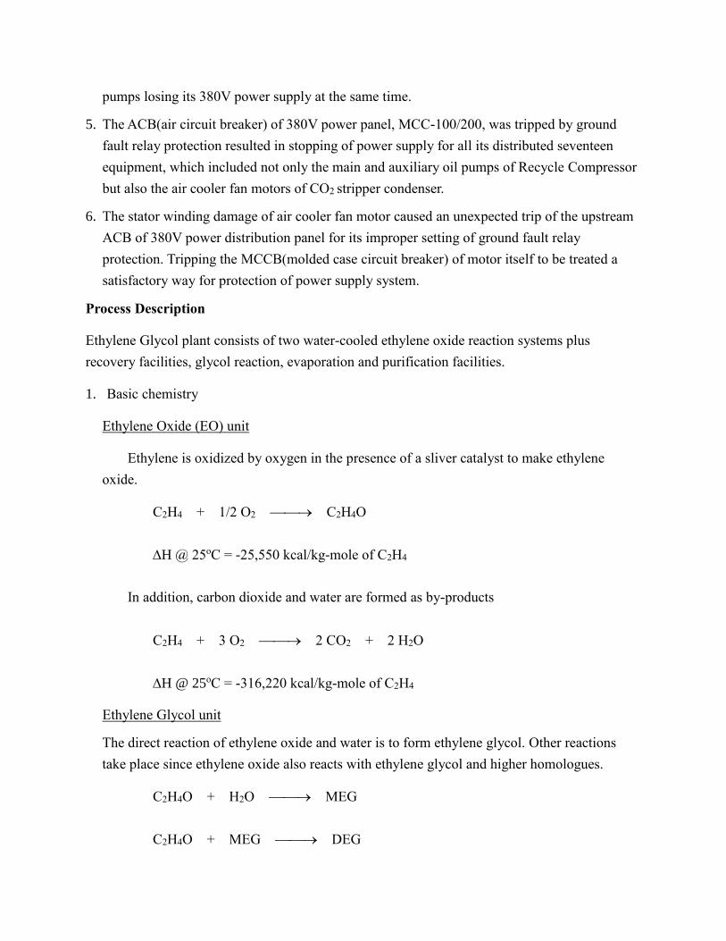
2. EO reactor unit description
Ethylene and oxygen enter from battery limits and are mixed with cycle gas. The gas mixture
from the Gas-Gas Exchanger flows downward through the tube of two EO Reactors where a
partial conversion of ethylene to ethylene oxide occurs over a solid catalyst. The heat of
reaction is removed by boiling water in the shell of the Reactor and producing steam. The
ethylene oxide is scrubbed from the Gas-Gas Exchanger shell side exit gas using EO lean
cycle water, and EO rich cycle water is sent to the Ethylene Oxide Stripping and Reabsorption
Section. A major portion of the lean (scrubbed) cycle gas is sent through the CO2 contactor
section to remove CO2 made in the EO Reactors. EO reactor unit scheme is shown in figure 1.
The Recycle Compressor provides the head necessary to circulate the large flow of cycle gas
through the reactors and scrubber.
Figure 1. EO reactor unit Scheme
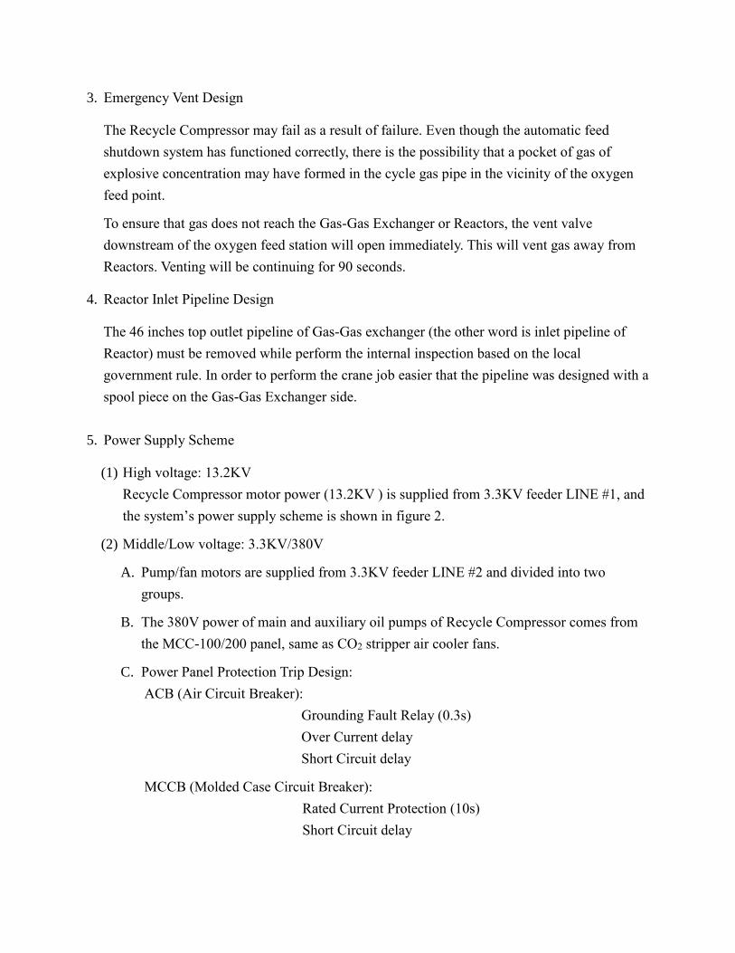
3. Emergency Vent Design
The Recycle Compressor may fail as a result of failure. Even though the automatic feed
shutdown system has functioned correctly, there is the possibility that a pocket of gas of
explosive concentration may have formed in the cycle gas pipe in the vicinity of the oxygen
feed point.
To ensure that gas does not reach the Gas-Gas Exchanger or Reactors, the vent valve
downstream of the oxygen feed station will open immediately. This will vent gas away from
Reactors. Venting will be continuing for 90 seconds.
4. Reactor Inlet Pipeline Design
The 46 inches top outlet pipeline of Gas-Gas exchanger (the other word is inlet pipeline of
Reactor) must be removed while perform the internal inspection based on the local
government rule. In order to perform the crane job easier that the pipeline was designed with a
spool piece on the Gas-Gas Exchanger side.
5. Power Supply Scheme
(1) High voltage: 13.2KV
Recycle Compressor motor power (13.2KV ) is supplied from 3.3KV feeder LINE #1, and
the system’s power supply scheme is shown in figure 2.
(2) Middle/Low voltage: 3.3KV/380V
A. Pump/fan motors are supplied from 3.3KV feeder LINE #2 and divided into two
groups.
B. The 380V power of main and auxiliary oil pumps of Recycle Compressor comes from
the MCC-100/200 panel, same as CO2 stripper air cooler fans.
C. Power Panel Protection Trip Design:
ACB (Air Circuit Breaker):
Grounding Fault Relay (0.3s)
Over Current delay
Short Circuit delay
MCCB (Molded Case Circuit Breaker):
Rated Current Protection (10s)
Short Circuit delay
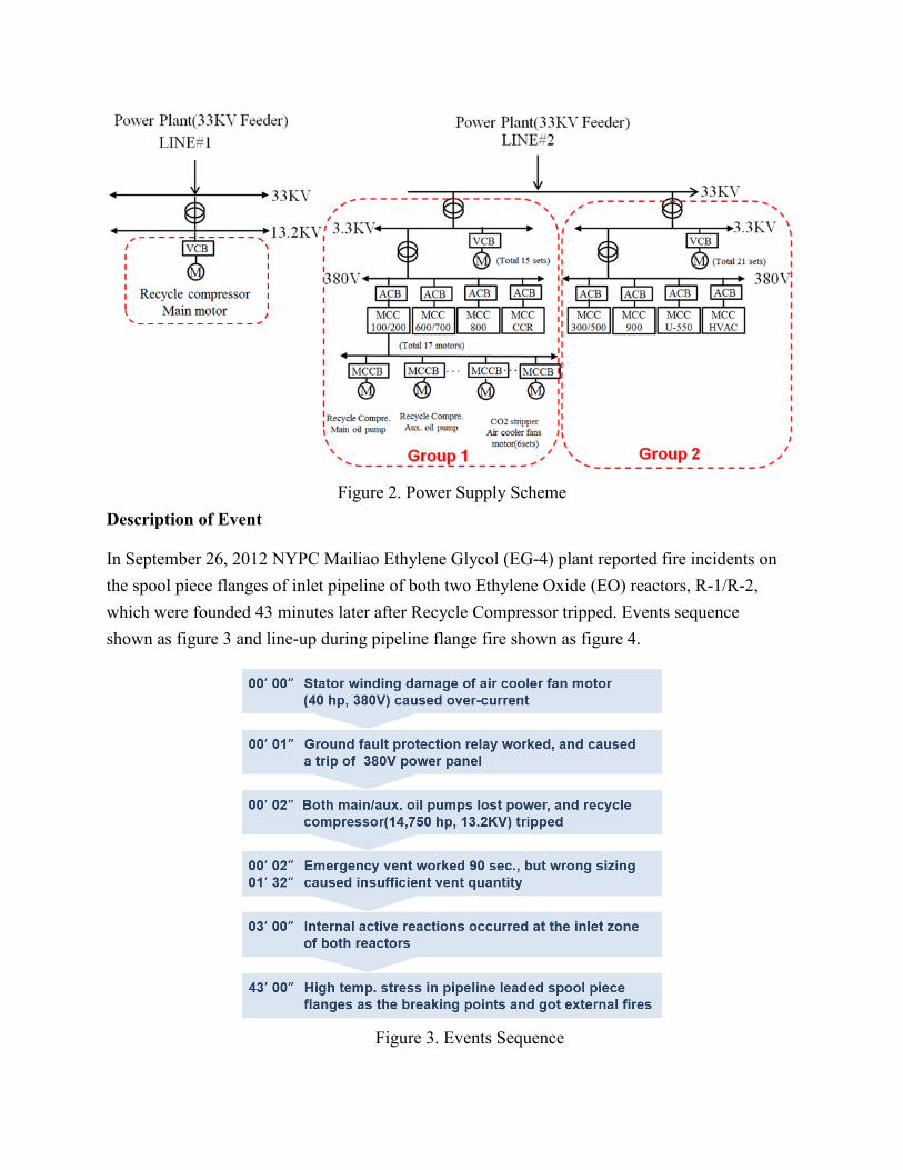
Figure 2. Power Supply Scheme
Description of Event
In September 26, 2012 NYPC Mailiao Ethylene Glycol (EG-4) plant reported fire incidents on
the spool piece flanges of inlet pipeline of both two Ethylene Oxide (EO) reactors, R-1/R-2,
which were founded 43 minutes later after Recycle Compressor tripped. Events sequence
shown as figure 3 and line-up during pipeline flange fire shown as figure 4.
Figure 3. Events Sequence
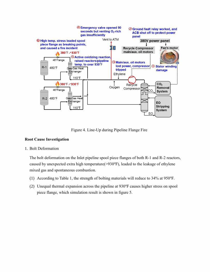
Figure 4. Line-Up during Pipeline Flange Fire
Root Cause Investigation
1. Bolt Deformation
The bolt deformation on the Inlet pipeline spool piece flanges of both R-1 and R-2 reactors,
caused by unexpected extra high temperature(>930℉), leaded to the leakage of ethylene
mixed gas and spontaneous combustion.
(1) According to Table 1, the strength of bolting materials will reduce to 34% at 950℉.
(2) Unequal thermal expansion across the pipeline at 930℉ causes higher stress on spool
piece flange, which simulation result is shown in figure 5.
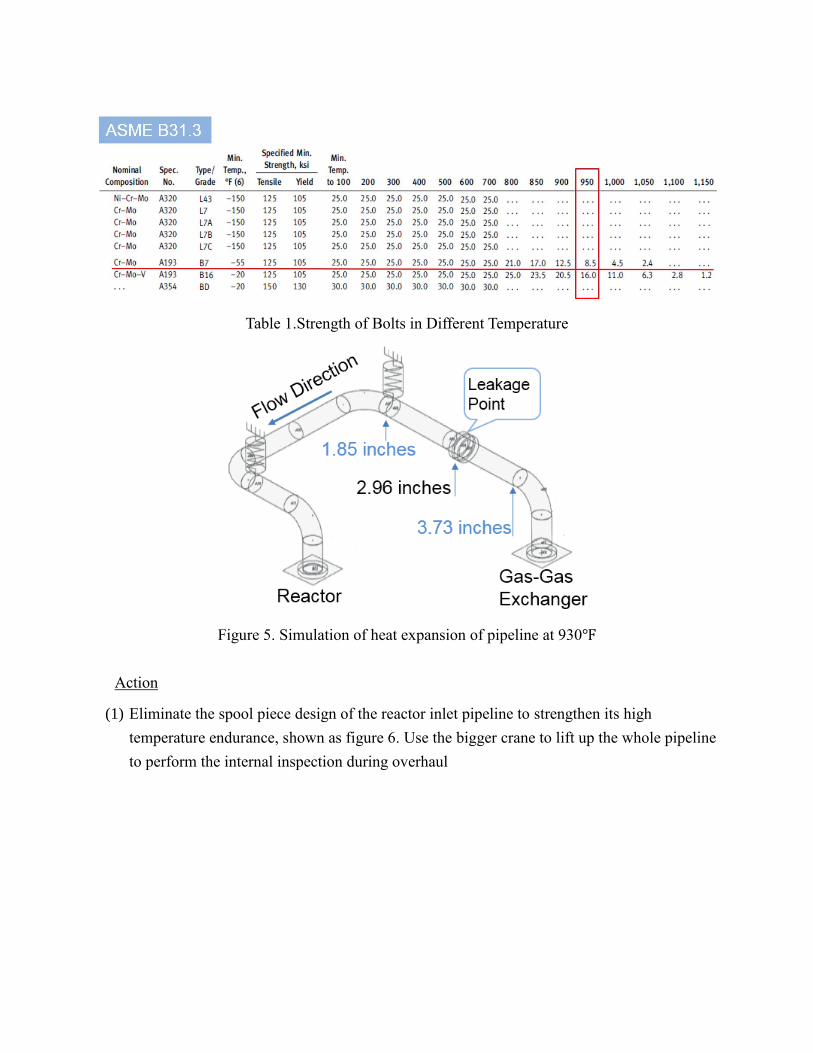
Table 1.Strength of Bolts in Different Temperature
Figure 5. Simulation of heat expansion of pipeline at 930℉
Action
(1) Eliminate the spool piece design of the reactor inlet pipeline to strengthen its high
temperature endurance, shown as figure 6. Use the bigger crane to lift up the whole pipeline
to perform the internal inspection during overhaul
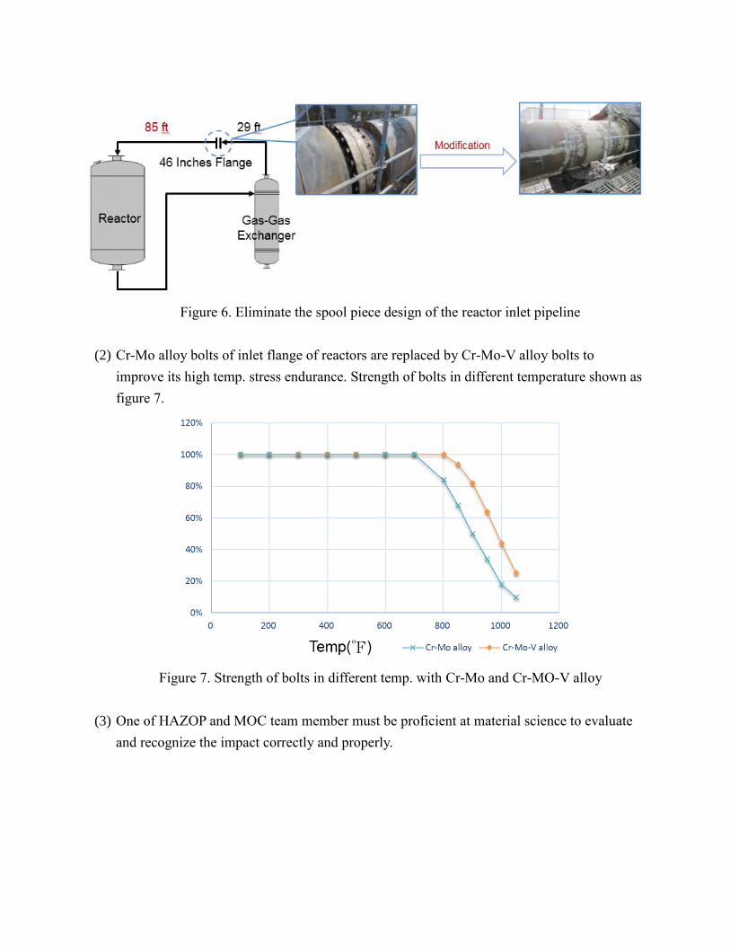
Figure 6. Eliminate the spool piece design of the reactor inlet pipeline
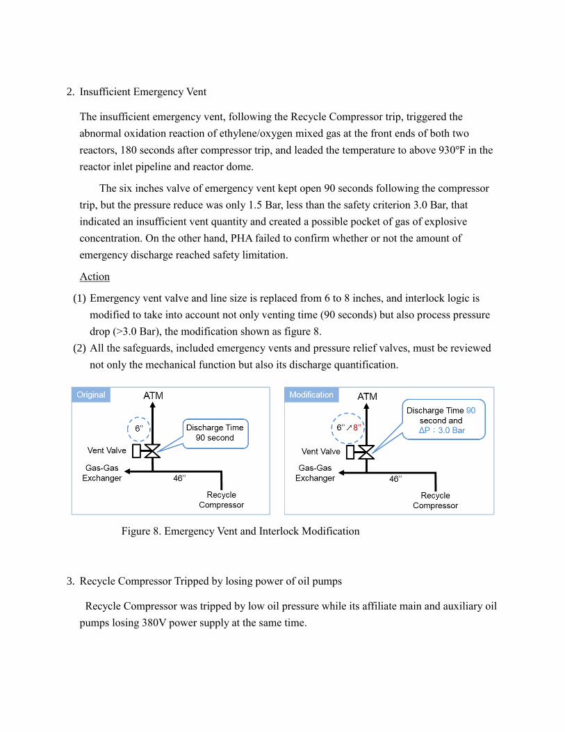
(2) Cr-Mo alloy bolts of inlet flange of reactors are replaced by Cr-Mo-V alloy bolts to
improve its high temp. stress endurance. Strength of bolts in different temperature shown as
figure 7.
Figure 7. Strength of bolts in different temp. with Cr-Mo and Cr-MO-V alloy
(3) One of HAZOP and MOC team member must be proficient at material science to evaluate
and recognize the impact correctly and properly.
2. Insufficient Emergency Vent
The insufficient emergency vent, following the Recycle Compressor trip, triggered the
abnormal oxidation reaction of ethylene/oxygen mixed gas at the front ends of both two
reactors, 180 seconds after compressor trip, and leaded the temperature to above 930℉ in the
reactor inlet pipeline and reactor dome.
The six inches valve of emergency vent kept open 90 seconds following the compressor
trip, but the pressure reduce was only 1.5 Bar, less than the safety criterion 3.0 Bar, that
indicated an insufficient vent quantity and created a possible pocket of gas of explosive
concentration. On the other hand, PHA failed to confirm whether or not the amount of
emergency discharge reached safety limitation.
Action
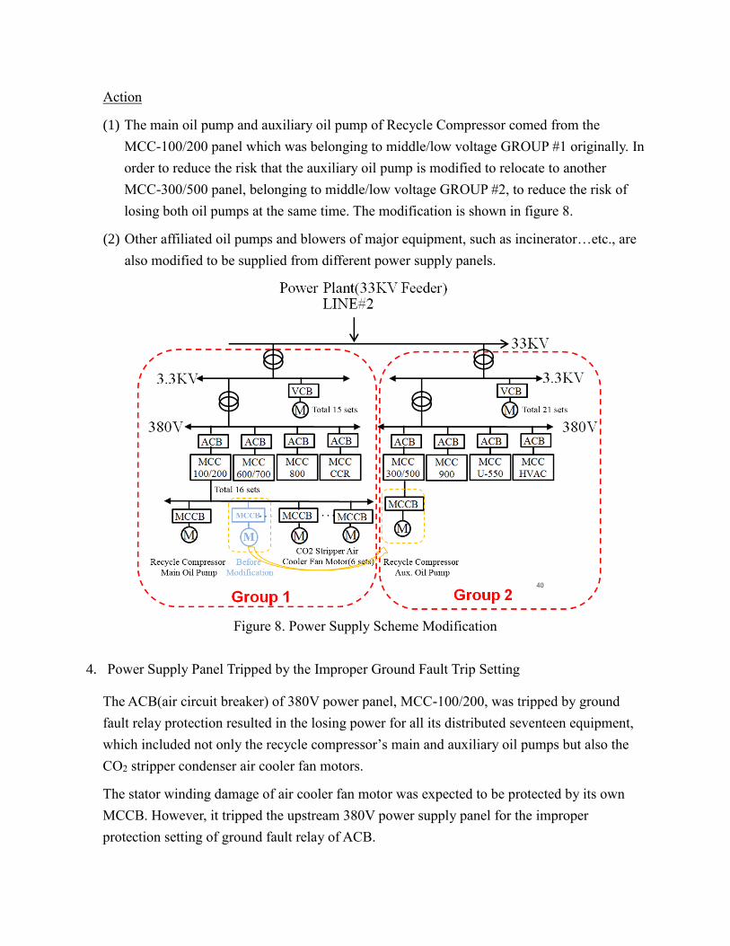
(1) Emergency vent valve and line size is replaced from 6 to 8 inches, and interlock logic is
modified to take into account not only venting time (90 seconds) but also process pressure
drop (>3.0 Bar), the modification shown as figure 8.
(2) All the safeguards, included emergency vents and pressure relief valves, must be reviewed
not only the mechanical function but also its discharge quantification.
Figure 8. Emergency Vent and Interlock Modification
3. Recycle Compressor Tripped by losing power of oil pumps
Recycle Compressor was tripped by low oil pressure while its affiliate main and auxiliary oil
pumps losing 380V power supply at the same time.
Action
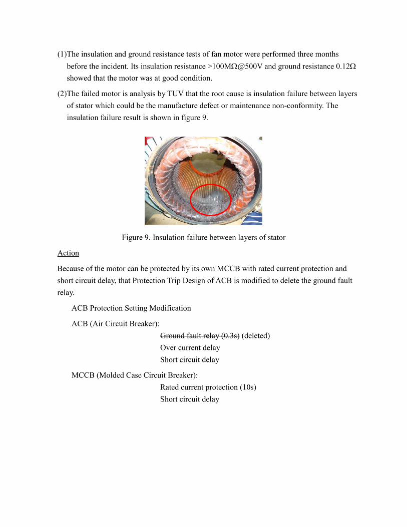
(1) The main oil pump and auxiliary oil pump of Recycle Compressor comed from the
MCC-100/200 panel which was belonging to middle/low voltage GROUP #1 originally. In
order to reduce the risk that the auxiliary oil pump is modified to relocate to another
MCC-300/500 panel, belonging to middle/low voltage GROUP #2, to reduce the risk of
losing both oil pumps at the same time. The modification is shown in figure 8.
(2) Other affiliated oil pumps and blowers of major equipment, such as incinerator…etc., are
also modified to be supplied from different power supply panels.
Figure 8. Power Supply Scheme Modification
4. Power Supply Panel Tripped by the Improper Ground Fault Trip Setting
The ACB(air circuit breaker) of 380V power panel, MCC-100/200, was tripped by ground
fault relay protection resulted in the losing power for all its distributed seventeen equipment,
which included not only the recycle compressor’s main and auxiliary oil pumps but also the
CO2 stripper condenser air cooler fan motors.
The stator winding damage of air cooler fan motor was expected to be protected by its own
MCCB. However, it tripped the upstream 380V power supply panel for the improper
protection setting of ground fault relay of ACB.
(1)The insulation and ground resistance tests of fan motor were performed three months
before the incident. Its insulation resistance >100M@500V and ground resistance 0.12
showed that the motor was at good condition.
(2)The failed motor is analysis by TUV that the root cause is insulation failure between layers
of stator which could be the manufacture defect or maintenance non-conformity. The
insulation failure result is shown in figure 9.
Figure 9. Insulation failure between layers of stator
Action
Because of the motor can be protected by its own MCCB with rated current protection and
short circuit delay, that Protection Trip Design of ACB is modified to delete the ground fault
relay.
ACB Protection Setting Modification
ACB (Air Circuit Breaker):
Ground fault relay (0.3s) (deleted)
Over current delay
Short circuit delay
MCCB (Molded Case Circuit Breaker):
Rated current protection (10s)
Short circuit delay
Conclusions
1. The spool piece for the potential oxidation pipeline must to be eliminated to strengthen its
high temperature endurance.
2. Emergency vent must be validated and confirmed.
3. Separated power supply scheme must be considered for the main and auxiliary oil pumps of
major compressor.
4. The coordination of protection settings between ACB of power supply panel and MCCB of
downstream terminal motors must be reviewed.
5. PHA group to assign a member specialized in materials to recognize the impact of process
deviation.


![Total No. of Questions : 9] [Total No. of Pages : 01 · PDF fileTotal No. of Questions : 9] [Total No. of Pages : 01 ... 13.2kV are connected in ... The operating voltage of motors](https://img.pdfslide.us/doc/110x75/5aa99f867f8b9a7c188d1657/total-no-of-questions-9-total-no-of-pages-01-no-of-questions-9-total.jpg)