Embed Size (px)
Citation preview
HOME AUTOMATION, INC.
Control & Security System
Owner's Manual
Document Number 20R00-2 Rev AFebruary, 2002

Copyright © 2001-2002 Home Automation, Inc.All Rights Reserved
ContentsINTRODUCTION........................................................................................................................................... 1
Underwriter's Laboratories (UL) Listing .........................................................................................................................................1
OVERALL DESCRIPTION.......................................................................................................................... 2
Console Operation ...........................................................................................................................................................................2
Normal Top-Level Display ..............................................................................................................................................................3
Display Menus .................................................................................................................................................................................3Main Menu..................................................................................................................................................................................4Error Beeps .................................................................................................................................................................................4Trouble Beeps.............................................................................................................................................................................4Confirmation Beep......................................................................................................................................................................5Cancel .........................................................................................................................................................................................5Time Out.....................................................................................................................................................................................5
Areas ................................................................................................................................................................................................5
OmniPro II Maintenance..................................................................................................................................................................5
SECURITY SYSTEM OPERATION ........................................................................................................... 6
Disarming the Security System and Silencing Alarms ....................................................................................................................6
Arming the Security System ............................................................................................................................................................6
Using Shortcut Keys ........................................................................................................................................................................7
Quick Arm .......................................................................................................................................................................................8
Bypassing Zones ..............................................................................................................................................................................8Auto-Bypass ...............................................................................................................................................................................8
Restoring Zones ...............................................................................................................................................................................8#=GOTO.....................................................................................................................................................................................9
What To Do When You Come Home ..............................................................................................................................................9
What Happens When the Alarm is Activated ..................................................................................................................................9Burglar Alarm Activated.............................................................................................................................................................9Fire Alarm Activated ................................................................................................................................................................10Gas Alarm Activated ................................................................................................................................................................10
Emergency Keys ............................................................................................................................................................................10Police Emergency .....................................................................................................................................................................11Fire Emergency.........................................................................................................................................................................11Auxiliary Emergency................................................................................................................................................................11
Duress Code Entered or Duress Alarm Activated..........................................................................................................................11
Alarm Reset ...................................................................................................................................................................................11
Alarm Cancel .................................................................................................................................................................................11
Trouble Indications ........................................................................................................................................................................12
Codes .............................................................................................................................................................................................12Master Code..............................................................................................................................................................................12Manager Code...........................................................................................................................................................................13User Code .................................................................................................................................................................................13
Duress Code...................................................................................................................................................................................13
Panic Switches ...............................................................................................................................................................................13
Area Arming ..................................................................................................................................................................................13
GOTO Area....................................................................................................................................................................................14
Testing Your System......................................................................................................................................................................15
CONTROL .................................................................................................................................................... 16
Control Commands ........................................................................................................................................................................16
ALC Switch Modules.....................................................................................................................................................................16ALC Module Types ..................................................................................................................................................................16
X-10 Modules ................................................................................................................................................................................16House Codes .............................................................................................................................................................................17Unit Numbers............................................................................................................................................................................17
Scrolling Through Names ..............................................................................................................................................................18
Controlling Units............................................................................................................................................................................19Dimming and Brightening ........................................................................................................................................................19Lighting Level...........................................................................................................................................................................19Ramp Command .......................................................................................................................................................................20Scene Command (Compose).....................................................................................................................................................20
Timed Commands ..........................................................................................................................................................................20
Status of a Unit...............................................................................................................................................................................21
Internal Flags .................................................................................................................................................................................21
Controlling Outputs........................................................................................................................................................................21
All On / Off....................................................................................................................................................................................21All Lights On ............................................................................................................................................................................22All Off.......................................................................................................................................................................................22
Leviton Scene Control ...................................................................................................................................................................22Scene.........................................................................................................................................................................................22
Scene Commands..................................................................................................................................................................22Scene Set Command .............................................................................................................................................................23Scene On Command..............................................................................................................................................................23Scene Off Command.............................................................................................................................................................23
Buttons ...........................................................................................................................................................................................23
Temperature Control ......................................................................................................................................................................24
HAI RC-Series Thermostats ..........................................................................................................................................................24
Programmable Energy Saver Modules (PESMs) ...........................................................................................................................26Freeze Alarms ...........................................................................................................................................................................27Outdoor Temperature................................................................................................................................................................28Temperature Control of Appliances..........................................................................................................................................28
Temperature Alarms ......................................................................................................................................................................28
Status..............................................................................................................................................................................................28
Event Log.......................................................................................................................................................................................31Show Events .............................................................................................................................................................................31
Messages ........................................................................................................................................................................................32Record Memo Message.............................................................................................................................................................32Play Memo Message .................................................................................................................................................................32Clear Text Messages .................................................................................................................................................................32Message ....................................................................................................................................................................................32
Show Message ......................................................................................................................................................................33Log Message .........................................................................................................................................................................33Clear Message.......................................................................................................................................................................33Say Message..........................................................................................................................................................................33Phone Message......................................................................................................................................................................33Send Message (Pro-Link)......................................................................................................................................................34
TELEPHONE CONTROL .......................................................................................................................... 35
Telephone Interface .......................................................................................................................................................................35
In-House Phones ............................................................................................................................................................................35
Remote Phones ..............................................................................................................................................................................35
Phone Access Denied - Remote Lockout.......................................................................................................................................36
Alternate Method ...........................................................................................................................................................................36
Main Menu.....................................................................................................................................................................................36
1 - Control......................................................................................................................................................................................37
2 - Security.....................................................................................................................................................................................37GOTO Area ..............................................................................................................................................................................37
3 - Button .......................................................................................................................................................................................37
4 - All .............................................................................................................................................................................................37
5 - Temperature..............................................................................................................................................................................37
6 - Status ........................................................................................................................................................................................38
7 - Events .......................................................................................................................................................................................38
8 - Message ....................................................................................................................................................................................39Playing and Recording a Message ............................................................................................................................................39Paging and Listening ................................................................................................................................................................39Playing and Recording a Custom Phrase ..................................................................................................................................39Playing and Recording the Address ..........................................................................................................................................40
9 - Good-Bye .................................................................................................................................................................................40
Panic Button over the Phone (# # # # # #) .....................................................................................................................................40
PC Access ......................................................................................................................................................................................41
Emergency Dial-Out ......................................................................................................................................................................41
Digital Dialer .................................................................................................................................................................................41
Voice Dialer...................................................................................................................................................................................41How the OmniPro II Voice Dialer Works ................................................................................................................................41What the OmniPro II Voice Dialer Does ..................................................................................................................................42What You Hear - If Your OmniPro II Calls You......................................................................................................................42Entering the Code .....................................................................................................................................................................42
SETUP............................................................................................................................................................ 43
Configuration and Advanced Control Programming (ACP)..........................................................................................................43
Set Up Codes .................................................................................................................................................................................43Authority Level.........................................................................................................................................................................431 = Master .................................................................................................................................................................................432 = Manager..............................................................................................................................................................................433 = User ....................................................................................................................................................................................43Access Areas.............................................................................................................................................................................43Duress Code..............................................................................................................................................................................44
Set Up Time ...................................................................................................................................................................................44
Advanced Control Programming (ACP)........................................................................................................................................451 = Add Programs.....................................................................................................................................................................452 = Show Programs...................................................................................................................................................................453 = Delete All Programs ...........................................................................................................................................................47
Edit Programs ................................................................................................................................................................................47
Edit Programs When ......................................................................................................................................................................48Times Programs ........................................................................................................................................................................48Button and Event Programs ......................................................................................................................................................49
Control Unit Event Buttons ..................................................................................................................................................49ALC Switch Module Activated Events.................................................................................................................................49
Security Mode Event Buttons ...............................................................................................................................................49Zone Event Buttons...............................................................................................................................................................50All On/Off Event Buttons .....................................................................................................................................................51Alarm Event Buttons.............................................................................................................................................................51X-10 Event Buttons...............................................................................................................................................................51Miscellaneous Event Buttons................................................................................................................................................52Message Event Buttons (Pro-Link) .......................................................................................................................................52
Edit Program Command.................................................................................................................................................................53Program Control Commands ....................................................................................................................................................53Program Security Commands ...................................................................................................................................................53Program Button Commands......................................................................................................................................................54Program All On / All Off Commands .......................................................................................................................................54Program Temperature Commands ............................................................................................................................................54Program Energy Cost ................................................................................................................................................................54Program Message Commands...................................................................................................................................................54
Edit Program Condition .................................................................................................................................................................55Program Control Conditions .....................................................................................................................................................55Program Security Mode Conditions..........................................................................................................................................55Program Zone Conditions .........................................................................................................................................................55Program Time Clock Conditions ..............................................................................................................................................56Program Other Conditions ........................................................................................................................................................56
Set Up Dial.....................................................................................................................................................................................57Telephone Access .....................................................................................................................................................................57
Answer Outside Call .............................................................................................................................................................57Remote Commands...............................................................................................................................................................57
Rings Before Answer ................................................................................................................................................................57Dial Type ..................................................................................................................................................................................57My Phone Number ....................................................................................................................................................................57Dial Out Number 1....................................................................................................................................................................58Dial Out Numbers 2-8...............................................................................................................................................................58Dial Order .................................................................................................................................................................................58
Set Up Arming ...............................................................................................................................................................................59Entry Delay ...............................................................................................................................................................................59
Exit Delay .............................................................................................................................................................................59Audible Exit Delay....................................................................................................................................................................59Entry/Exit Chime ......................................................................................................................................................................59Perimeter Chime .......................................................................................................................................................................59Enable Quick Arm ....................................................................................................................................................................60Enable Auto Bypass..................................................................................................................................................................60All On For Alarm......................................................................................................................................................................60Beep On Trouble.......................................................................................................................................................................60
Set up Miscellaneous .....................................................................................................................................................................60High Security Mode..................................................................................................................................................................60Announce Alarms .....................................................................................................................................................................60Enable Freeze Alarm.................................................................................................................................................................61Flash For Alarm ........................................................................................................................................................................61X-10 House Code 1 Format ......................................................................................................................................................61X-10 House Codes 2-16 Format ...............................................................................................................................................61House Code 1 X-10 All Off ......................................................................................................................................................61House Code 1 X-10 All On.......................................................................................................................................................61House Codes 2-16 X-10 All Off ...............................................................................................................................................62House Codes 2-16 X-10 All On ................................................................................................................................................62Time Clocks ..............................................................................................................................................................................62Latitude, Longitude, and Time Zone.........................................................................................................................................63Daylight Savings.......................................................................................................................................................................63
Set Up Names.................................................................................................................................................................................64
Set Up Voice ..................................................................................................................................................................................65
Set Up Address...............................................................................................................................................................................65
UNDERWRITER'S LABORATORIES REQUIREMENTS ................................................................... 66
FIRE ESCAPE PLANNING..........................................................................................................................................................66
FEDERAL COMMUNICATION COMMISSION NOTICE: ................................................................. 67
CANADIAN INDUSTRY CANADA NOTICE.......................................................................................... 68
APPENDIX A - DIAL OUT PLANNER..................................................................................................... 69
INSTRUCTIONS TO CALLED PARTY......................................................................................................................................70
APPENDIX B - TEXT DESCRIPTION CHARACTER CODES............................................................ 71
APPENDIX C - VOICE DESCRIPTION CODES.................................................................................... 72
NOTES ON CUSTOM PHRASES................................................................................................................................................75

Page 1
INTRODUCTION
Thank you for purchasing your new OmniPro II automation system. You are about to enjoy a new feeling of security, comfort,convenience, and control. OmniPro II coordinates lighting, heating and air, security, scenes, and messages based on your lifestyleand schedule.
Please take a few moments to become familiar with all of the features of your system by reviewing this manual. Please keep thismanual on file for future reference.
It is recommended that you also review the installation and operating instructions provided with your smoke and gas detectors (ifused in your system). If you do not have a copy of these documents, ask your installer - See Underwriter's LaboratoriesRequirements.
In the event that there are any questions, please call your installer first. If you need assistance directly from the manufacturer, callus at (504) 736-9810, between the hours of 9:00 AM and 5:00 PM Central Time, Monday-Friday. We will be happy to assist you.
When calling, please have the model and serial number of your unit, which can be found on the inside of the controller.
For your convenience, we suggest that you record this information:
MODEL NUMBER: ________________________
SERIAL NUMBER: ________________________
Underwriter's Laboratories (UL) Listing
The 20A00-2, -5, and -22 OmniPro II controllers and consoles have been tested and Listed by UL for the following applications:
• UL 985 - Household Fire Warning System Units
• UL 1023 - Household Burglar Alarm System Units (Grade A)
The 20A00-5 OmniPro II controller has also been tested and Listed by UL for the following applications:
• UL 365 - Police Station Connected Burglar Alarm Units and Systems (Grade A)
• UL 609 - Local Burglar Alarm Units and Systems (Grade A)
• UL 1610 - Central Station Burglar Alarm Units (Grade B, C)
In a UL Listed Installation, failure to operate and program the system as described in this manual is a violation of the ListingMark.
See Underwriter's Laboratories Requirements for more information.
Page 2
OVERALL DESCRIPTION
Console Operation
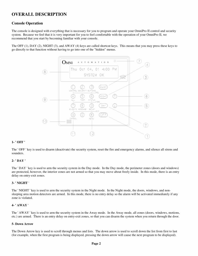
The console is designed with everything that is necessary for you to program and operate your OmniPro II control and securitysystem. Because we feel that it is very important for you to feel comfortable with the operation of your OmniPro II, werecommend that you start by becoming familiar with your console.
The OFF (1), DAY (2), NIGHT (3), and AWAY (4) keys are called shortcut keys. This means that you may press these keys togo directly to that function without having to go into one of the "hidden" menus.
A U T O M A T I O NOMNI
1- ' OFF '
The ' OFF ' key is used to disarm (deactivate) the security system, reset the fire and emergency alarms, and silence all sirens andsounders.
2- ' DAY '
The ' DAY ' key is used to arm the security system in the Day mode. In the Day mode, the perimeter zones (doors and windows)are protected, however, the interior zones are not armed so that you may move about freely inside. In this mode, there is an entrydelay on entry-exit zones.
3- ' NIGHT '
The ' NIGHT ' key is used to arm the security system in the Night mode. In the Night mode, the doors, windows, and non-sleeping area motion detectors are armed. In this mode, there is no entry delay so the alarm will be activated immediately if anyzone is violated.
4- ' AWAY '
The ' AWAY ' key is used to arm the security system in the Away mode. In the Away mode, all zones (doors, windows, motions,etc.) are armed. There is an entry delay on entry-exit zones, so that you can disarm the system when you return through the door.
5- Down Arrow
The Down Arrow key is used to scroll through menus and lists. The down arrow is used to scroll down the list from first to last(for example, when the first program is being displayed, pressing the down arrow will cause the next program to be displayed).
Page 3
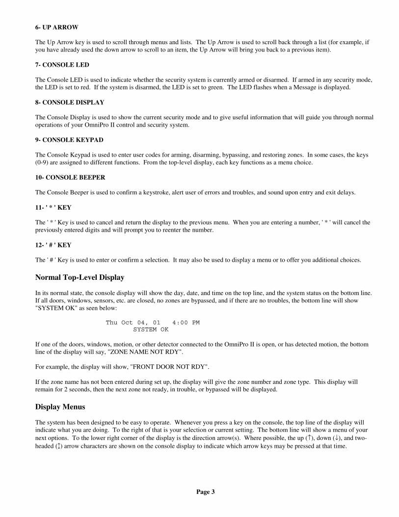
6- UP ARROW
The Up Arrow key is used to scroll through menus and lists. The Up Arrow is used to scroll back through a list (for example, ifyou have already used the down arrow to scroll to an item, the Up Arrow will bring you back to a previous item).
7- CONSOLE LED
The Console LED is used to indicate whether the security system is currently armed or disarmed. If armed in any security mode,the LED is set to red. If the system is disarmed, the LED is set to green. The LED flashes when a Message is displayed.
8- CONSOLE DISPLAY
The Console Display is used to show the current security mode and to give useful information that will guide you through normaloperations of your OmniPro II control and security system.
9- CONSOLE KEYPAD
The Console Keypad is used to enter user codes for arming, disarming, bypassing, and restoring zones. In some cases, the keys(0-9) are assigned to different functions. From the top-level display, each key functions as a menu choice.
10- CONSOLE BEEPER
The Console Beeper is used to confirm a keystroke, alert user of errors and troubles, and sound upon entry and exit delays.
11- ' * ' KEY
The ' * ' Key is used to cancel and return the display to the previous menu. When you are entering a number, ' * ' will cancel thepreviously entered digits and will prompt you to reenter the number.
12- ' # ' KEY
The ' # ' Key is used to enter or confirm a selection. It may also be used to display a menu or to offer you additional choices.
Normal Top-Level Display
In its normal state, the console display will show the day, date, and time on the top line, and the system status on the bottom line.If all doors, windows, sensors, etc. are closed, no zones are bypassed, and if there are no troubles, the bottom line will show"SYSTEM OK" as seen below:
Thu Oct 04, 01 4:00 PM SYSTEM OK
If one of the doors, windows, motion, or other detector connected to the OmniPro II is open, or has detected motion, the bottomline of the display will say, "ZONE NAME NOT RDY".
For example, the display will show, "FRONT DOOR NOT RDY".
If the zone name has not been entered during set up, the display will give the zone number and zone type. This display willremain for 2 seconds, then the next zone not ready, in trouble, or bypassed will be displayed.
Display Menus
The system has been designed to be easy to operate. Whenever you press a key on the console, the top line of the display willindicate what you are doing. To the right of that is your selection or current setting. The bottom line will show a menu of yournext options. To the lower right corner of the display is the direction arrow(s). Where possible, the up (↑), down (↓), and two-headed (↕) arrow characters are shown on the console display to indicate which arrow keys may be pressed at that time.
Page 4
When using the arrow keys to scroll through lists of areas, buttons, codes, temperature zones, units, or zones, only the nameditems are displayed. If no text description has been given to an item, it will be skipped over when scrolling through that list. Youcan still enter any item number to access it directly, and then scroll up and down among the named items. To look at anotherspecific item, simply enter the item number followed by the Down Arrow key.
In some cases, the keypad keys (0-9, *, #) are assigned to different functions or menus. A key assignment is indicated by thecharacter key directly in front of the new function on the bottom line of the display. For example, if the bottom line says,"2=DELETE", you may press the 2 key to delete. From the top-level display, each key functions as a menu choice. Simply pressthe appropriate key and you will enter that menu.
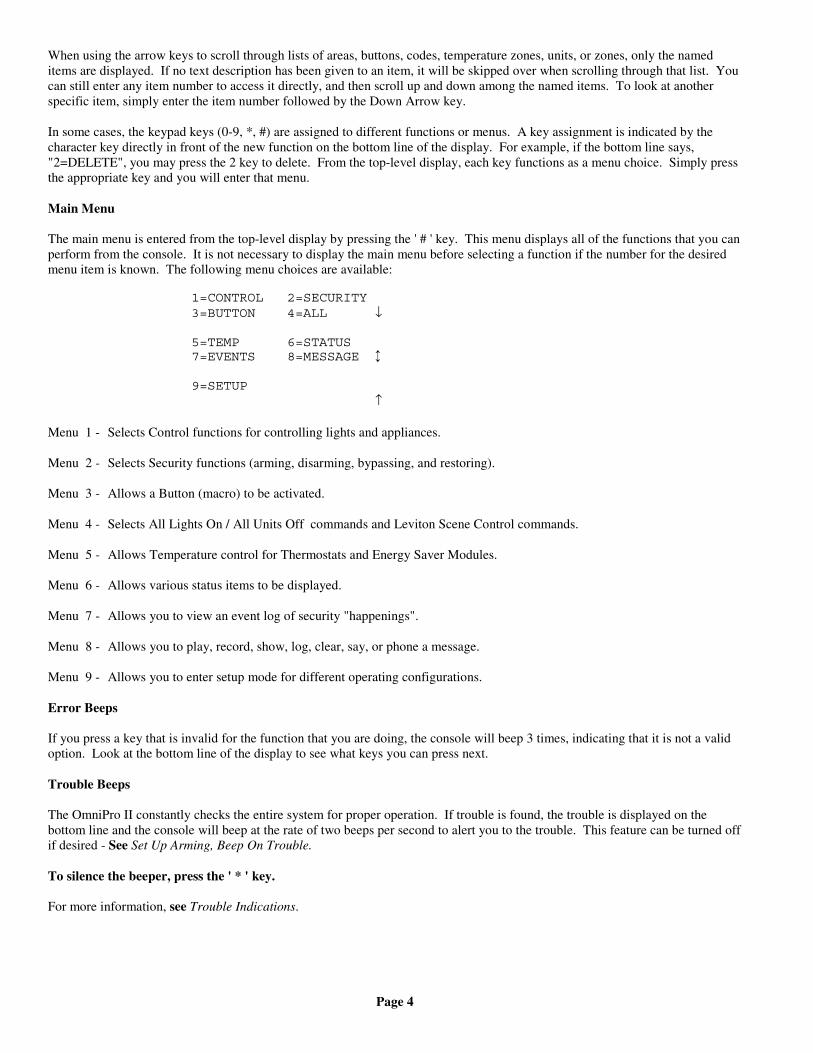
Main Menu
The main menu is entered from the top-level display by pressing the ' # ' key. This menu displays all of the functions that you canperform from the console. It is not necessary to display the main menu before selecting a function if the number for the desiredmenu item is known. The following menu choices are available:
1=CONTROL 2=SECURITY3=BUTTON 4=ALL ↓
5=TEMP 6=STATUS7=EVENTS 8=MESSAGE ↕
9=SETUP ↑
Menu 1 - Selects Control functions for controlling lights and appliances.
Menu 2 - Selects Security functions (arming, disarming, bypassing, and restoring).
Menu 3 - Allows a Button (macro) to be activated.
Menu 4 - Selects All Lights On / All Units Off commands and Leviton Scene Control commands.
Menu 5 - Allows Temperature control for Thermostats and Energy Saver Modules.
Menu 6 - Allows various status items to be displayed.
Menu 7 - Allows you to view an event log of security "happenings".
Menu 8 - Allows you to play, record, show, log, clear, say, or phone a message.
Menu 9 - Allows you to enter setup mode for different operating configurations.
Error Beeps
If you press a key that is invalid for the function that you are doing, the console will beep 3 times, indicating that it is not a validoption. Look at the bottom line of the display to see what keys you can press next.
Trouble Beeps
The OmniPro II constantly checks the entire system for proper operation. If trouble is found, the trouble is displayed on thebottom line and the console will beep at the rate of two beeps per second to alert you to the trouble. This feature can be turned offif desired - See Set Up Arming, Beep On Trouble.
To silence the beeper, press the ' * ' key.
For more information, see Trouble Indications.
Page 5
Confirmation Beep
When you have successfully completed a function, such as entering a program or changing a setup item, the console will beeponce.
Cancel
If you are ever unsure and wish to return to the top-level display, press the ' * ' key. You may have to press it more than once,depending on how far into the function (menu) you are. Each time you cancel out of an operation, the console will beep once toindicate that you have canceled.
The ' * ' key can also be used if you make a mistake while entering a number. For example, if you enter a 2 when you meant toenter a 3, press the ' * ' key to start over.
Time Out
If you are called away from the console for any reason (to take a phone call, for instance) while you are engaged in an operation,the console will "time out" and cancel it for you after 3 minutes. The display will return to the normal top-level display.
Areas
If there is an area or a separate building that needs to be protected, your installer can divide your OmniPro II system into twoindependent security systems: Area 1 through Area 8 (up to 8 Areas). Each area has complete access to all of the capabilities ofthe OmniPro II, yet the OmniPro II can protect each area individually.
You may decide to use the Area feature if you have a guesthouse or workshop that you would like to have protected separatelyfrom your home, or maybe you have a business and would like to protect an inventory stockroom separately from the offices inyour building.
The console in each area acts as if it were controlling its own OmniPro II system. Each area is assigned, by your installer, aconsole, a group of zones, control units, macro buttons, messages, and thermostats. These items can only be controlled wherethey have been assigned.
OmniPro II Maintenance
Your OmniPro II controller and the consoles are designed to require very little maintenance.
For smoke detectors, motion detectors, and other components not manufactured by HAI and follow maintenance proceduresoutlined by the manufacturer.
Consoles can be cleaned using a mild detergent and a soft cloth.
Every three years, or if the "BATTERY LOW TROUBLE NOW" indication comes on and stays on for an extended periodwithout reason, the rechargeable battery in the controller should be replaced. The recommended battery type is a 12-volt, 7 amp-hour sealed lead-acid battery.
To replace the battery, disconnect the red battery wire from the battery (+) terminal. Cover the connector at the end of the wirewith electrical tape to avoid its touching anything in the enclosure. Disconnect the black wire from the battery (-) terminal andcover the connector at the end of the black wire with tape. Remove the old battery. Install the new battery by reversing theremoval procedure. Be very careful to connect the Black wire to the (-) terminal on the battery; Red wire to the (+) terminal.
Page 6
SECURITY SYSTEM OPERATION
Disarming the Security System and Silencing Alarms
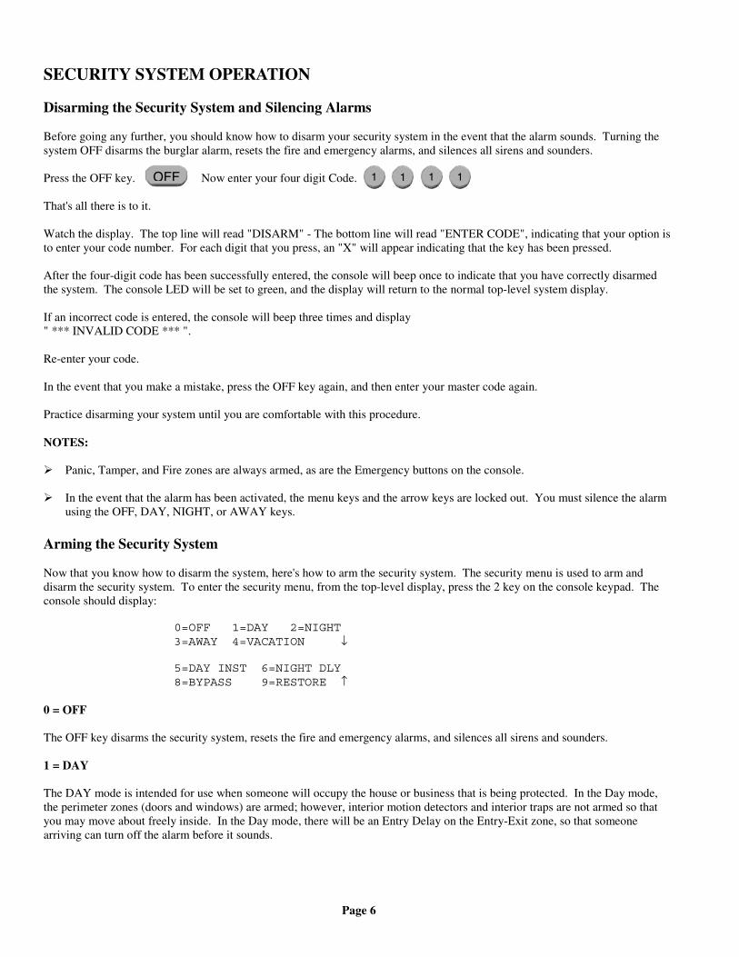
Before going any further, you should know how to disarm your security system in the event that the alarm sounds. Turning thesystem OFF disarms the burglar alarm, resets the fire and emergency alarms, and silences all sirens and sounders.
Press the OFF key. Now enter your four digit Code.
That's all there is to it.
Watch the display. The top line will read "DISARM" - The bottom line will read "ENTER CODE", indicating that your option isto enter your code number. For each digit that you press, an "X" will appear indicating that the key has been pressed.
After the four-digit code has been successfully entered, the console will beep once to indicate that you have correctly disarmedthe system. The console LED will be set to green, and the display will return to the normal top-level system display.
If an incorrect code is entered, the console will beep three times and display" *** INVALID CODE *** ".
Re-enter your code.
In the event that you make a mistake, press the OFF key again, and then enter your master code again.
Practice disarming your system until you are comfortable with this procedure.
NOTES:
Panic, Tamper, and Fire zones are always armed, as are the Emergency buttons on the console.
In the event that the alarm has been activated, the menu keys and the arrow keys are locked out. You must silence the alarmusing the OFF, DAY, NIGHT, or AWAY keys.
Arming the Security System
Now that you know how to disarm the system, here's how to arm the security system. The security menu is used to arm anddisarm the security system. To enter the security menu, from the top-level display, press the 2 key on the console keypad. Theconsole should display:
0=OFF 1=DAY 2=NIGHT3=AWAY 4=VACATION ↓
5=DAY INST 6=NIGHT DLY8=BYPASS 9=RESTORE ↑
0 = OFF
The OFF key disarms the security system, resets the fire and emergency alarms, and silences all sirens and sounders.
1 = DAY
The DAY mode is intended for use when someone will occupy the house or business that is being protected. In the Day mode,the perimeter zones (doors and windows) are armed; however, interior motion detectors and interior traps are not armed so thatyou may move about freely inside. In the Day mode, there will be an Entry Delay on the Entry-Exit zone, so that someonearriving can turn off the alarm before it sounds.
OFF 1 1 1 1
Page 7
2 = NIGHT
The NIGHT mode is used when you are asleep and everyone in your household is at home. In the Night mode, your doors,windows, and non-sleeping area (i.e. downstairs) motion detectors are armed. In the Night mode, there is no entry delay. Thealarm system sounder will be activated immediately if any door, window, or non-sleeping area (motion detector) is tripped.
3 = AWAY
Use the AWAY mode when you leave your house and no one is home. All doors, windows, and motion detectors are armed. Allzones have an Exit Delay so that you will have time to leave and close the door after you arm the system. The system will befully armed after the Exit Delay. There is an Entry Delay on the Entry-Exit zones in the Away mode, so that you will have timeto turn the system off when you return through your door.
Note that the Entry Delay only applies if you come in through an Entry-Exit zone. If someone attempts to climb into a window,or if an interior zone is tripped before the Entry-Exit zone, the alarm will be activated immediately. If you do enter through anEntry-Exit zone first, then the other zones are disabled during the Entry Delay, in case you have to cross through another zone toget to your console (an interior motion detector, for example).
4 = VACATION
This mode arms all doors, windows, and interior motion detectors (same as Away mode). There is an Entry Delay on the Entry-Exit zones. Use this mode when you are leaving for a period of days.
5 = DAY INST (DAY INSTANT)
Functions same as Day mode, however, there is no Entry Delay on any of the security zones. There will be an instant alarm if anyof the zones are violated while in this mode.
6 = NIGHT DLY (NIGHT DELAY)
Functions same as Night mode, however, there is an Entry Delay on the Entry-Exit zones. Use this mode if you are going to sleepbut a family member is expected home at a later time.
To arm the system into one of the 6 security modes, from the security menu, choose the security mode and press the appropriatekey (1 - 6).
Enter your user code number on the console keypad.
The console will beep once and the console LED will be set to red. The top line will display the security mode. The bottom linewill display, " *** ARMING SYSTEM *** " to indicate that the system is being armed. The system will be fully armed after theExit Delay expires. If arming in Away or Vacation mode and Audible Exit Delay is enabled, the console will beep until the ExitDelay has expired. During the last 10 second of the Exit Delay, the console will beep twice as fast so leave and close the doorpromptly.
NOTE: In Commercial Burglar Alarm Applications for UL Certified Systems, a Ring-back indication and Bell-test should beheard after arming (closing). If not heard, call for service.
Using Shortcut Keys
There are three shortcut keys on the console to arm the system in the Day, Night, and Away security modes, and Off to disarm,without having to go into the security menu.
From the top-level display, press one of the shortcut security keys. Enter your code number on the console keypad.
The console will beep once and the console LED will be set to red. The top line will display the security mode to indicate thatyou have correctly armed the system. The system will be fully armed after the Exit Delay expires.
The programmed Entry Delay is __________ seconds.The programmed Exit Delay is __________ seconds.
Page 8
Quick Arm
For extra convenience, the OmniPro II can be armed by simply pressing the DAY, NIGHT, or AWAY button twice, eliminatingthe need to enter the code.
To quick arm the system in the Away mode, from the top-level display, press .
The quick arm feature only works if the alarm system is in the Off mode, and if no alarms are sounding. This feature is disabledwhen the system is shipped. If desired, it can be enabled or disabled at any time - See Set Up Arming, Enable Quick Arm.
Bypassing Zones
8 = BYPASS
You can Bypass a zone that you do not want protected while the system is armed. Bypassing is also the only way that a tamper orpanic zone can be disarmed. For example, if there is a liquor closet or gun case on a tamper zone, then you must bypass that zoneto gain access to it.
Another reason to Bypass a zone is if the zone is having trouble. If a zone is causing a trouble indication, you can bypass thatzone to "cut it out" of the system until repairs are made.
When a zone is bypassed, it is no longer checked for alarms. When you bypass a zone using the console (or over the phone) itwill Stay bypassed until you Restore it. The console status display will show that the zone is bypassed only when the securitysystem is disarmed. When the system is armed, it does not display bypassed zones.
To bypass a zone, from the main menu or from the top-level display, press 2 on the console keypad, then 8 for bypass. Enter thezone number followed by the ' # ' key, or use the arrow keys to select the zone. After the zone is entered, you will be prompted toenter your security code. The bottom line will now read "ZONE NAME BYPASSED" to remind you that the zone is bypassed.
If a fire zone is bypassed, the console will continue to beep until that zone is restored - See Restoring Zones.
Auto-Bypass
In order to prevent the alarm from sounding unexpectedly if a window or door is open when the system is armed, the OmniPro IIwill automatically bypass the zone if it is opened when the system is armed.
Note that there is an exit delay before the system is armed in any mode. The bypass will only take place if the zone is not ready(i.e. open) when the exit delay is over and the system is actually armed.
When a zone is Auto-Bypassed, it will be automatically restored once it is secure (i.e. closed), or the next time you arm or disarmthe system. The auto-bypass is recorded in the event log as "ZONE NAME BYPASSED". To prevent any zone from beingbypassed unintentionally, you should always look for "SYSTEM OK" on the display before arming and leaving the premises.
The Auto-Bypass feature can be disabled if you do not want the system to automatically bypass open zones. If the auto-bypassfeature is disabled, the alarm will sound if a zone not ready (i.e. open) when the system is armed.
NOTE: The Auto-Bypass feature is disabled on UL Listed Installations.
Restoring Zones
9 = RESTORE
Restoring a zone puts it back on active duty in the system. When restored, the Bypassed indication will no longer be displayed onthe status line and the zone will be checked for alarms.
To restore a zone, from the top-level display, press 2 on the console keypad, then 9 for restore.
Enter the zone number followed by the ' # ' key, or use the arrow keys to select the zone. Press ' 0 ' as the first key to restore allzones. The 0 = ALL choice is removed once a digit key or the down arrow is pressed. After the zone or all zones is entered, youwill be prompted to enter your code. The console will beep and the display will return to the top-level display.
AWAY AWAY
Page 9
#=GOTO
To Bypass or Restore a zone in another area, you must first "go to" that area by selecting #=GOTO.
AREA:ENTER AREA:
At this point you may enter the area number followed by the ' # ' key, or use the down arrow key to scroll to the next area - SeeArea Arming for additional information.
What To Do When You Come Home
Entry through a door:
If you enter your home while the system is armed in the Day or Away modes, using your normal entry door:
• Console beeper comes on - display indicates: " *** DISARM SYSTEM *** - PRESS OFF THEN CODE"
• Any lights or control modules programmed to come on for the door that you used will do so.
• The system will wait the Entry Delay time.
You should go to your console (or telephone) immediately and turn the security system off. If you wish, you may go directly to adifferent security mode, rather than turning the system Off.
If you return home and hear the alarm sounding, DO NOT ENTER. Use a neighbor's phone to call for help.
What Happens When the Alarm is Activated
Burglar Alarm Activated
If someone enters through any zone other than an Entry-Exit zone, if the security system is in the Night mode, or if the securitysystem is not turned off during the Entry Delay:
• The sounder is activated, which makes a loud, continuous sound.
• The display shows the type of alarm and the zones that have been tripped:"BURGLAR ALARM! - ZONE NAME TRIPPED".
If more than one zone is tripped, then the bottom line will show each zone tripped for two seconds.
• The When Alarm macro is activated. Any units programmed to come on will do so.
• The Flash For Alarm Unit Number begins to flash on and off.
• The system waits the Outside Siren Delay (0 - 60 seconds), then activates the sounder.
• The system waits the Dial Out Delay (0 - 60 seconds), then if programmed, the in-house phones are seized(disconnected) and the OmniPro II begins to dial out.
If you are having your system monitored by a central station, the central station will be sent a code representing the type of alarm(burglary) and zone involved. In most cases, the central station will call back, requesting your password or passcode.
If you are not using central station monitoring but are using the voice dial out capability, the system looks at the Dial Order todetermine which number to call first, and calls that number.
If you are using both central station monitoring and voice dial out, then the voice dial out is delayed by five minutes to give thecentral station time to call you back.
Page 10
For more information on the digital and voice dialer - See Digital Dialer and Voice Dialer.
• The system continues to sound all alarms and flash the flashing light for 1-30 minutes after the alarm is activated.
• After a 1-30 minute period, the sounder is turned off, and the alarm system resets itself. The console beeper stays on.If a zone is tripped after a reset, the sounder will again be activated, and the dialer will again dial out.
At any time, the alarm system can be turned off at the console.
Fire Alarm Activated
When the fire alarm is activated by the smoke/fire detector(s), the alarm responds exactly as described under Burglar AlarmActivated, except:
• The console display reads, "FIRE ALARM! ZONE NAME TRIPPED".
• The sounder will activate in a 3 pulse temporal pattern to distinguish the fire alarm from the burglar alarm.
The fire alarm takes priority over the burglar alarm, however, if a gas alarm is already active, it will not override the gas alarm.
NOTE: If multiple alarm types occur, such as both Fire and Police, the display will alternate between the alarm types.
Gas Alarm Activated
When the gas alarm is activated, the alarm responds exactly as described under Burglar Alarm Activated, except:
• The console display reads, "GAS ALARM! ZONE NAME TRIPPED".
• The sounder will pulse on - off - on, then an extended off period to distinguish it from the burglar or fire alarm.
The gas alarm takes priority over the burglar alarm, however, if a fire alarm is already active, it will not override the fire alarm.
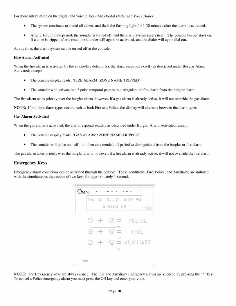
Emergency Keys
Emergency alarm conditions can be activated through the console. These conditions (Fire, Police, and Auxiliary) are initiatedwith the simultaneous depression of two keys for approximately 1-second.
A U T O M A T I O NOMNI
NOTE: The Emergency keys are always armed. The Fire and Auxiliary emergency alarms are silenced by pressing the ' * ' key.To cancel a Police emergency alarm you must press the Off key and enter your code.
Page 11
Police Emergency
When the 1 key and the 3 keys are pressed simultaneously, the Police Emergency alarm is activated. This alarm operates exactlythe same as described for Burglar Alarm Activated except:
• The console display indicates: "BURGLARY! - POLICE EMERG TRIPPED".
• The interior sounder and the outdoor siren are activated immediately. There is no outside siren delay.
Fire Emergency
When the 4 key and the 6 key is pressed simultaneously, the Fire Emergency alarm is activated. This alarm operates exactly thesame as described for Police Emergency Button except:
• The sounders activates in a 3 pulse temporal pattern distinguish the fire alarm from the burglar alarm.
• The console display will read: "FIRE ALM - FIRE EMERG TRIPPED".
The Fire Emergency alarm can be turned off at any time by pressing the ' * ' key.
Auxiliary Emergency
When the 7 key and the 9 key is pressed simultaneously, the Auxiliary Emergency alarm is activated.
• The console beeper comes on - display indicates: "AUX ALARM! AUX EMG BTN TRIPPED".
• The console beeper continues to sound until the alarm is reset.
Duress Code Entered or Duress Alarm Activated
(See Duress Code for a description of when to use)
In the event that you enter your duress code or a Duress zone is tripped, the system performs a silent dial out as follows:
• No alarms, lights or console beepers are activated. The system does not display the duress alarm.
• The system waits the dial out delay, then begins to dial out.
If you are having your system monitored, the central station will be sent a code representing a silent alarm (duress).
Alarm Reset
The alarm system will reset itself after the outside siren has been on for 1-30 minutes. When the alarm system resets, any zonethat is ready is reactivated, so the alarm system will be activated again if the zone is tripped. If a zone remains not ready (i.e. adoor has been left open) it will be automatically bypassed when the alarm resets.
Alarm Cancel
At any time, you can silence your alarm system by pressing the Off key and entering your code. If the system has reported, or isin the process of reporting an alarm to a central station, it will send the alarm code followed by a code indicating that the user hascanceled the alarm. If an alarm is canceled before the dial out delay has expired, the system will not report any alarm.
If an alarm is canceled during a voice dial out, the system hangs up immediately.
Page 12
Trouble Indications
The OmniPro II constantly monitors the alarm zones and several internal matters and will alert you if it detects trouble. Theparticular trouble is indicated on the bottom line of the display and a trouble signal is given by beeping the console beepercontinuously, 2 beeps per second.
When any trouble condition occurs, the console will beep twice per second and continue to beep until the ' * ' key (cancel) ispressed to acknowledge the trouble. The console will say "TRBL NOW" (trouble now) if the trouble condition actually existswhile you are looking at the console. It will say "HAD TRBL" (had trouble) if the trouble occurred and then corrected itself.
The following are trouble indications and their meanings:
ZONE NAME TRBL NOW or HAD TRBL: If the reading for a zone becomes abnormal, trouble will be indicated on thatzone -See Status \ Test. Excessive resistance in the contact and wiring usually causes trouble on security zones. If the causeis not obvious, call your installer for service.
AC POWER OFF TRBL NOW or HAD TRBL: Indicated if the normal house current powering the OmniPro II controlleris interrupted for more than 3 minutes. If this happens without good cause, check the wall mounted transformer to ensurethat it hasn't come out of the wall socket and check to see that the socket has power.
BATTERY LOW TRBL NOW or HAD TRBL: Every hour, the OmniPro II takes a dynamic test of the battery. If thebattery voltage is too low, then the console will indicate "BATTERY LOW". If this happens, make sure that the battery isconnected. The "BATTERY LOW" indication will remain until the next battery test is executed, 1 hour later, or when aStatus | Test command is given.
COMMUNICATOR TRBL NOW or HAD TRBL: Indicated if the digital communicator (not the voice dialer) was unableto make contact with the Central Station after trying both numbers multiple times. If this happens, there could be a problemwith the system, central station, or the phone line. Call your installer for service.
FUSE TRBL NOW or HAD TRBL: Indicated when the solid state fuse that protects the "Auxiliary" power supply opens.The fuse will automatically reset when the fault condition is cleared.
PHONE LINE DEAD TRBL NOW or HAD TRBL: Indicated if the phone line is dead for more than 1 minute.
To silence the trouble beeps on the console, press the ' * ' key. If more than one type of trouble has occurred, the display willshow each one for two seconds. Pressing the ' * ' key will acknowledge all trouble indications.
If the trouble condition occurs again, the console beeper will beep again - See Set Up Arming, Beep On Trouble if you wish todisable the beeper.
NO CONTROLLER DATA: Indicated when console's alarm functions are no longer operational. This may indicate awiring problem to the console or a more serious problem. Call your installer for service.
Codes
There are 99 user codes that you may assign to users of the system. All OmniPro II codes are 4 digits in length. A code can beany number from 0001 to 9999. Each user should be assigned a security code with an authority level, areas that can be accessed(if area arming is used), and times and days in which the code will be valid. Memorize your codes! Don't give them to anyonewho doesn't need to know them.
The levels of authority that you can assign to a user code are Master, Manager, and User.
Master Code
The Master code allows complete access to the entire system. Only the owner(s) or the one(s) who will govern the system shouldhave and use the master code. A Master code is allowed access to all areas, all the time.
User code 1 is always set to a Master code - See Set Up Codes.
Page 13
Manager Code
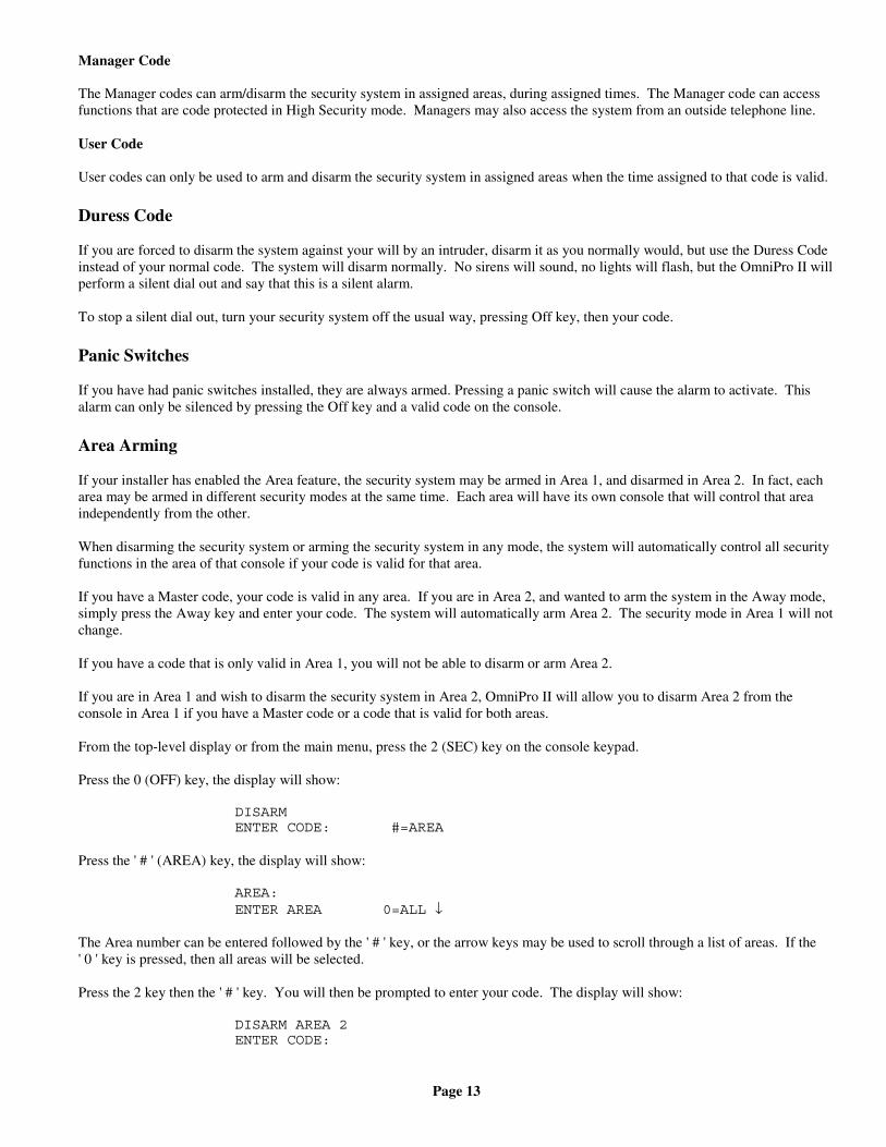
The Manager codes can arm/disarm the security system in assigned areas, during assigned times. The Manager code can accessfunctions that are code protected in High Security mode. Managers may also access the system from an outside telephone line.
User Code
User codes can only be used to arm and disarm the security system in assigned areas when the time assigned to that code is valid.
Duress Code
If you are forced to disarm the system against your will by an intruder, disarm it as you normally would, but use the Duress Codeinstead of your normal code. The system will disarm normally. No sirens will sound, no lights will flash, but the OmniPro II willperform a silent dial out and say that this is a silent alarm.
To stop a silent dial out, turn your security system off the usual way, pressing Off key, then your code.
Panic Switches
If you have had panic switches installed, they are always armed. Pressing a panic switch will cause the alarm to activate. Thisalarm can only be silenced by pressing the Off key and a valid code on the console.
Area Arming
If your installer has enabled the Area feature, the security system may be armed in Area 1, and disarmed in Area 2. In fact, eacharea may be armed in different security modes at the same time. Each area will have its own console that will control that areaindependently from the other.
When disarming the security system or arming the security system in any mode, the system will automatically control all securityfunctions in the area of that console if your code is valid for that area.
If you have a Master code, your code is valid in any area. If you are in Area 2, and wanted to arm the system in the Away mode,simply press the Away key and enter your code. The system will automatically arm Area 2. The security mode in Area 1 will notchange.
If you have a code that is only valid in Area 1, you will not be able to disarm or arm Area 2.
If you are in Area 1 and wish to disarm the security system in Area 2, OmniPro II will allow you to disarm Area 2 from theconsole in Area 1 if you have a Master code or a code that is valid for both areas.
From the top-level display or from the main menu, press the 2 (SEC) key on the console keypad.
Press the 0 (OFF) key, the display will show:
DISARMENTER CODE: #=AREA
Press the ' # ' (AREA) key, the display will show:
AREA:ENTER AREA 0=ALL ↓
The Area number can be entered followed by the ' # ' key, or the arrow keys may be used to scroll through a list of areas. If the' 0 ' key is pressed, then all areas will be selected.
Press the 2 key then the ' # ' key. You will then be prompted to enter your code. The display will show:
DISARM AREA 2ENTER CODE:
Page 14
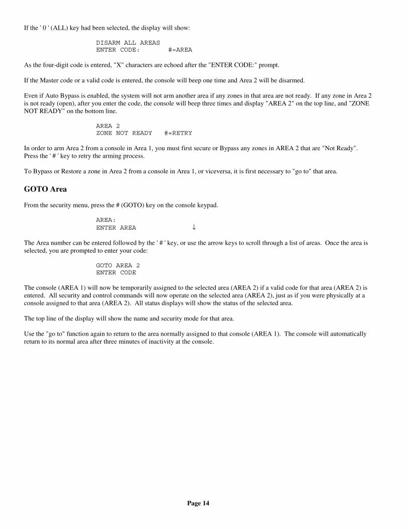
If the ' 0 ' (ALL) key had been selected, the display will show:
DISARM ALL AREASENTER CODE: #=AREA
As the four-digit code is entered, "X" characters are echoed after the "ENTER CODE:" prompt.
If the Master code or a valid code is entered, the console will beep one time and Area 2 will be disarmed.
Even if Auto Bypass is enabled, the system will not arm another area if any zones in that area are not ready. If any zone in Area 2is not ready (open), after you enter the code, the console will beep three times and display "AREA 2" on the top line, and "ZONENOT READY" on the bottom line.
AREA 2ZONE NOT READY #=RETRY
In order to arm Area 2 from a console in Area 1, you must first secure or Bypass any zones in AREA 2 that are "Not Ready".Press the ' # ' key to retry the arming process.
To Bypass or Restore a zone in Area 2 from a console in Area 1, or viceversa, it is first necessary to "go to" that area.
GOTO Area
From the security menu, press the # (GOTO) key on the console keypad.
AREA:ENTER AREA ↓
The Area number can be entered followed by the ' # ' key, or use the arrow keys to scroll through a list of areas. Once the area isselected, you are prompted to enter your code:
GOTO AREA 2ENTER CODE
The console (AREA 1) will now be temporarily assigned to the selected area (AREA 2) if a valid code for that area (AREA 2) isentered. All security and control commands will now operate on the selected area (AREA 2), just as if you were physically at aconsole assigned to that area (AREA 2). All status displays will show the status of the selected area.
The top line of the display will show the name and security mode for that area.
Use the "go to" function again to return to the area normally assigned to that console (AREA 1). The console will automaticallyreturn to its normal area after three minutes of inactivity at the console.
Page 15
Testing Your System
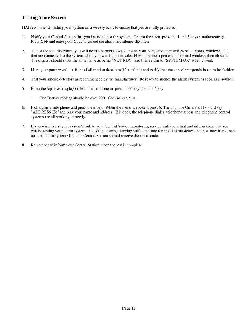
HAI recommends testing your system on a weekly basis to ensure that you are fully protected.
1. Notify your Central Station that you intend to test the system. To test the siren, press the 1 and 3 keys simultaneously.Press OFF and enter your Code to cancel the alarm and silence the siren.
2. To test the security zones, you will need a partner to walk around your home and open and close all doors, windows, etc.that are connected to the system while you watch the console. Have a partner open each door and window, then close it.The display should show the zone name as being "NOT RDY" and then return to "SYSTEM OK" when closed.
3. Have your partner walk in front of all motion detectors (if installed) and verify that the console responds in a similar fashion.
4. Test your smoke detectors as recommended by the manufacturer. Be ready to silence the alarm system as soon as it sounds.
5. From the top-level display or from the main menu, press the 6 key then the 4 key.
- The Battery reading should be over 200 - See Status \ Test.
6. Pick up an inside phone and press the # key. When the menu is spoken, press 8, Then 3. The OmniPro II should say"ADDRESS IS: "and play your name and address. If it does, the telephone dialer, telephone access and telephone controlsystems are all working correctly.
7. If you wish to test your system's link to your Central Station monitoring service, call them first and inform them that youwill be testing your alarm system. Set off the alarm, allowing sufficient time for any dial out delays that you may have, thenturn the alarm system Off. The Central Station should receive the alarm code.
8. Remember to inform your Central Station when the test is complete.
Page 16
CONTROL
Control Commands
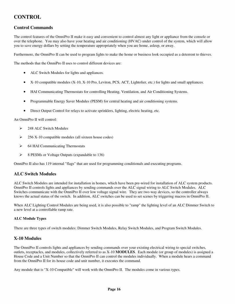
The control features of the OmniPro II make it easy and convenient to control almost any light or appliance from the console orover the telephone. You may also have your heating and air conditioning (HVAC) under control of the system, which will allowyou to save energy dollars by setting the temperature appropriately when you are home, asleep, or away.
Furthermore, the OmniPro II can be used to program lights to make the home or business look occupied as a deterrent to thieves.
The methods that the OmniPro II uses to control different devices are:
• ALC Switch Modules for lights and appliances.
• X-10 compatible modules (X-10, X-10 Pro, Leviton, PCS, ACT, Lightolier, etc.) for lights and small appliances.
• HAI Communicating Thermostats for controlling Heating, Ventilation, and Air Conditioning Systems.
• Programmable Energy Saver Modules (PESM) for central heating and air conditioning systems.
• Direct Output Control for relays to activate sprinklers, lighting, electric heating, etc.
An OmniPro II will control:
248 ALC Switch Modules
256 X-10 compatible modules (all sixteen house codes)
64 HAI Communicating Thermostats
8 PESMs or Voltage Outputs (expandable to 136)
OmniPro II also has 119 internal "flags" that are used for programming conditionals and executing programs.
ALC Switch Modules
ALC Switch Modules are intended for installation in homes, which have been pre-wired for installation of ALC system products.OmniPro II controls lights and appliances by sending commands over the ALC signal wiring to ALC Switch Modules. ALCSwitches communicate with the OmniPro II over low voltage signal wire. They are two-way devices, so the controller alwaysknows the actual status of the switch. In addition, ALC switches can be used to set scenes by triggering macros in OmniPro II.
When ALC Lighting Control Modules are being used, it is also possible to "ramp" the lighting level of an ALC Dimmer Switch toa new level at a controllable ramp rate.
ALC Module Types
There are three types of switch modules: Dimmer Switch Modules, Relay Switch Modules, and Program Switch Modules.
X-10 Modules
The OmniPro II controls lights and appliances by sending commands over your existing electrical wiring to special switches,outlets, receptacles, and modules, collectively referred to as X-10 MODULES. Each module (or group of modules) is assigned aHouse Code and a Unit Number so that the OmniPro II can control the modules individually. When a module hears a commandfrom the OmniPro II for its house code and unit number, it executes the command.
Any module that is "X-10 Compatible" will work with the OmniPro II. The modules come in various types.
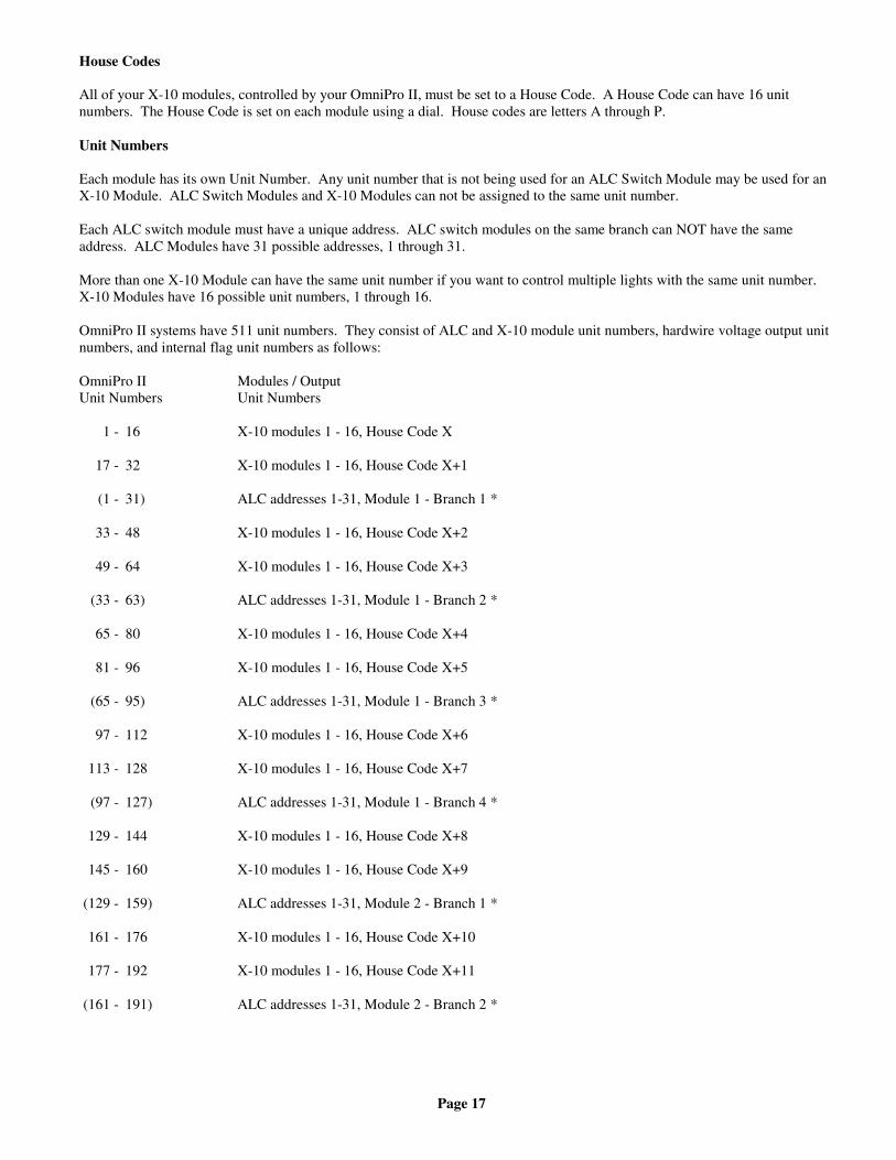
Page 17
House Codes
All of your X-10 modules, controlled by your OmniPro II, must be set to a House Code. A House Code can have 16 unitnumbers. The House Code is set on each module using a dial. House codes are letters A through P.
Unit Numbers
Each module has its own Unit Number. Any unit number that is not being used for an ALC Switch Module may be used for anX-10 Module. ALC Switch Modules and X-10 Modules can not be assigned to the same unit number.
Each ALC switch module must have a unique address. ALC switch modules on the same branch can NOT have the sameaddress. ALC Modules have 31 possible addresses, 1 through 31.
More than one X-10 Module can have the same unit number if you want to control multiple lights with the same unit number.X-10 Modules have 16 possible unit numbers, 1 through 16.
OmniPro II systems have 511 unit numbers. They consist of ALC and X-10 module unit numbers, hardwire voltage output unitnumbers, and internal flag unit numbers as follows:
OmniPro II Modules / OutputUnit Numbers Unit Numbers
1 - 16 X-10 modules 1 - 16, House Code X
17 - 32 X-10 modules 1 - 16, House Code X+1
(1 - 31) ALC addresses 1-31, Module 1 - Branch 1 *
33 - 48 X-10 modules 1 - 16, House Code X+2
49 - 64 X-10 modules 1 - 16, House Code X+3
(33 - 63) ALC addresses 1-31, Module 1 - Branch 2 *
65 - 80 X-10 modules 1 - 16, House Code X+4
81 - 96 X-10 modules 1 - 16, House Code X+5
(65 - 95) ALC addresses 1-31, Module 1 - Branch 3 *
97 - 112 X-10 modules 1 - 16, House Code X+6
113 - 128 X-10 modules 1 - 16, House Code X+7
(97 - 127) ALC addresses 1-31, Module 1 - Branch 4 *
129 - 144 X-10 modules 1 - 16, House Code X+8
145 - 160 X-10 modules 1 - 16, House Code X+9
(129 - 159) ALC addresses 1-31, Module 2 - Branch 1 *
161 - 176 X-10 modules 1 - 16, House Code X+10
177 - 192 X-10 modules 1 - 16, House Code X+11
(161 - 191) ALC addresses 1-31, Module 2 - Branch 2 *
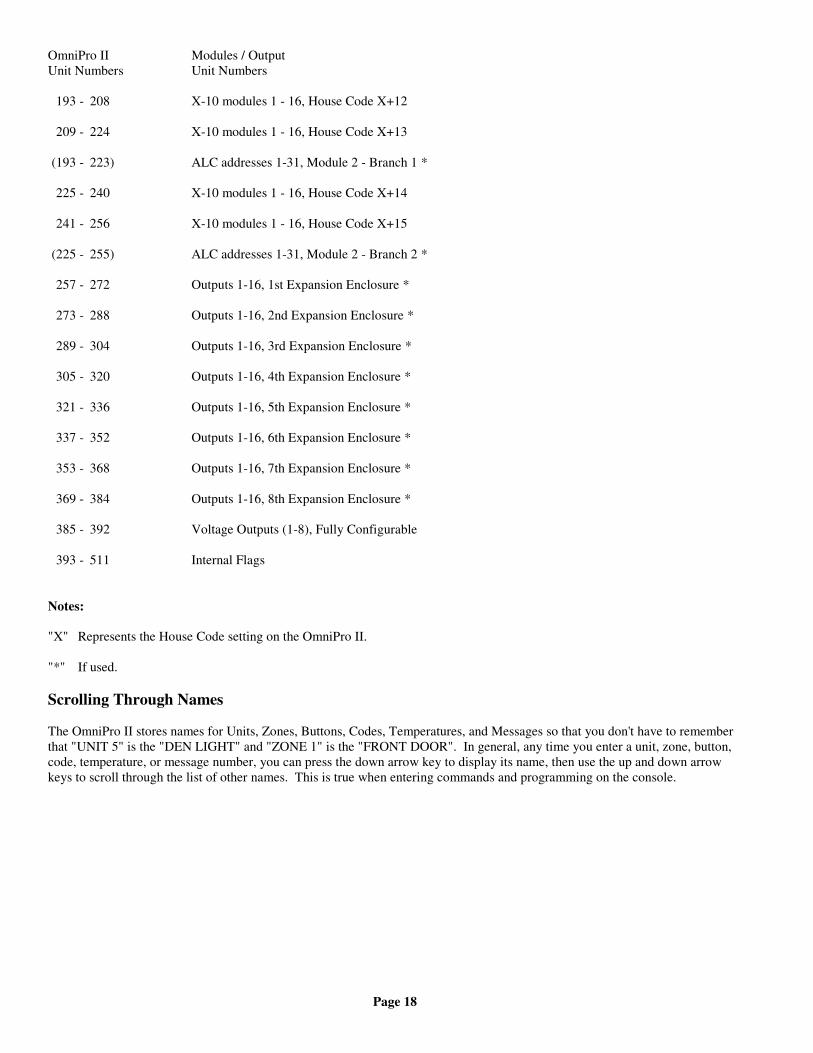
Page 18
OmniPro II Modules / OutputUnit Numbers Unit Numbers
193 - 208 X-10 modules 1 - 16, House Code X+12
209 - 224 X-10 modules 1 - 16, House Code X+13
(193 - 223) ALC addresses 1-31, Module 2 - Branch 1 *
225 - 240 X-10 modules 1 - 16, House Code X+14
241 - 256 X-10 modules 1 - 16, House Code X+15
(225 - 255) ALC addresses 1-31, Module 2 - Branch 2 *
257 - 272 Outputs 1-16, 1st Expansion Enclosure *
273 - 288 Outputs 1-16, 2nd Expansion Enclosure *
289 - 304 Outputs 1-16, 3rd Expansion Enclosure *
305 - 320 Outputs 1-16, 4th Expansion Enclosure *
321 - 336 Outputs 1-16, 5th Expansion Enclosure *
337 - 352 Outputs 1-16, 6th Expansion Enclosure *
353 - 368 Outputs 1-16, 7th Expansion Enclosure *
369 - 384 Outputs 1-16, 8th Expansion Enclosure *
385 - 392 Voltage Outputs (1-8), Fully Configurable
393 - 511 Internal Flags
Notes:
"X" Represents the House Code setting on the OmniPro II.
"*" If used.
Scrolling Through Names
The OmniPro II stores names for Units, Zones, Buttons, Codes, Temperatures, and Messages so that you don't have to rememberthat "UNIT 5" is the "DEN LIGHT" and "ZONE 1" is the "FRONT DOOR". In general, any time you enter a unit, zone, button,code, temperature, or message number, you can press the down arrow key to display its name, then use the up and down arrowkeys to scroll through the list of other names. This is true when entering commands and programming on the console.
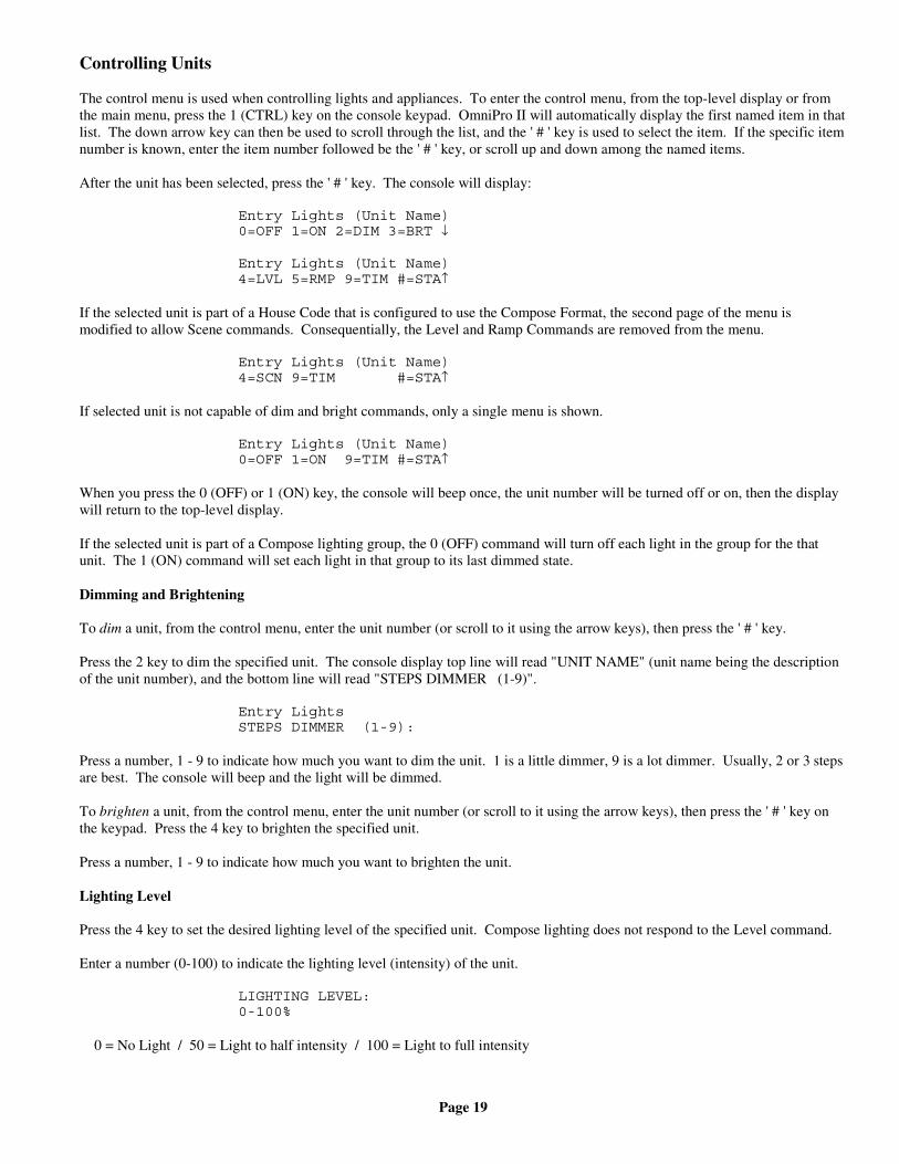
Page 19
Controlling Units
The control menu is used when controlling lights and appliances. To enter the control menu, from the top-level display or fromthe main menu, press the 1 (CTRL) key on the console keypad. OmniPro II will automatically display the first named item in thatlist. The down arrow key can then be used to scroll through the list, and the ' # ' key is used to select the item. If the specific itemnumber is known, enter the item number followed be the ' # ' key, or scroll up and down among the named items.
After the unit has been selected, press the ' # ' key. The console will display:
Entry Lights (Unit Name)0=OFF 1=ON 2=DIM 3=BRT ↓
Entry Lights (Unit Name)4=LVL 5=RMP 9=TIM #=STA↑
If the selected unit is part of a House Code that is configured to use the Compose Format, the second page of the menu ismodified to allow Scene commands. Consequentially, the Level and Ramp Commands are removed from the menu.
Entry Lights (Unit Name)4=SCN 9=TIM #=STA↑
If selected unit is not capable of dim and bright commands, only a single menu is shown.
Entry Lights (Unit Name)0=OFF 1=ON 9=TIM #=STA↑
When you press the 0 (OFF) or 1 (ON) key, the console will beep once, the unit number will be turned off or on, then the displaywill return to the top-level display.
If the selected unit is part of a Compose lighting group, the 0 (OFF) command will turn off each light in the group for the thatunit. The 1 (ON) command will set each light in that group to its last dimmed state.
Dimming and Brightening
To dim a unit, from the control menu, enter the unit number (or scroll to it using the arrow keys), then press the ' # ' key.
Press the 2 key to dim the specified unit. The console display top line will read "UNIT NAME" (unit name being the descriptionof the unit number), and the bottom line will read "STEPS DIMMER (1-9)".
Entry LightsSTEPS DIMMER (1-9):
Press a number, 1 - 9 to indicate how much you want to dim the unit. 1 is a little dimmer, 9 is a lot dimmer. Usually, 2 or 3 stepsare best. The console will beep and the light will be dimmed.
To brighten a unit, from the control menu, enter the unit number (or scroll to it using the arrow keys), then press the ' # ' key onthe keypad. Press the 4 key to brighten the specified unit.
Press a number, 1 - 9 to indicate how much you want to brighten the unit.
Lighting Level
Press the 4 key to set the desired lighting level of the specified unit. Compose lighting does not respond to the Level command.
Enter a number (0-100) to indicate the lighting level (intensity) of the unit.
LIGHTING LEVEL:0-100%
0 = No Light / 50 = Light to half intensity / 100 = Light to full intensity
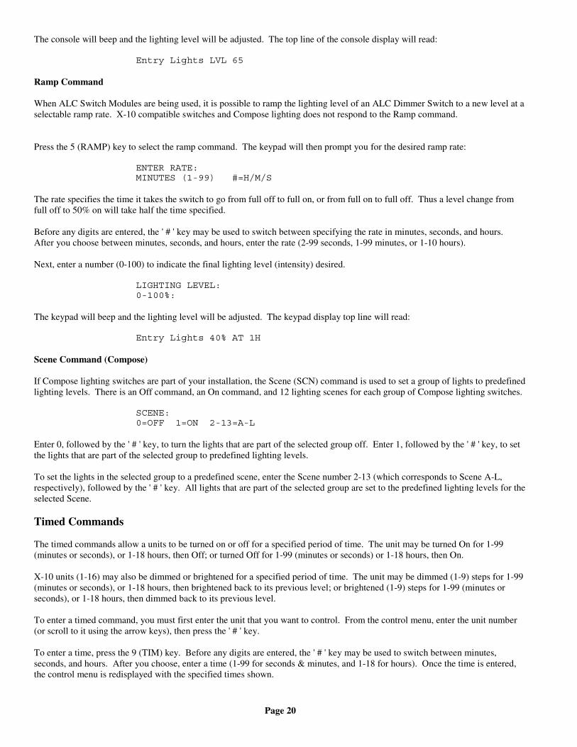
Page 20
The console will beep and the lighting level will be adjusted. The top line of the console display will read:
Entry Lights LVL 65
Ramp Command
When ALC Switch Modules are being used, it is possible to ramp the lighting level of an ALC Dimmer Switch to a new level at aselectable ramp rate. X-10 compatible switches and Compose lighting does not respond to the Ramp command.
Press the 5 (RAMP) key to select the ramp command. The keypad will then prompt you for the desired ramp rate:
ENTER RATE:MINUTES (1-99) #=H/M/S
The rate specifies the time it takes the switch to go from full off to full on, or from full on to full off. Thus a level change fromfull off to 50% on will take half the time specified.
Before any digits are entered, the ' # ' key may be used to switch between specifying the rate in minutes, seconds, and hours.After you choose between minutes, seconds, and hours, enter the rate (2-99 seconds, 1-99 minutes, or 1-10 hours).
Next, enter a number (0-100) to indicate the final lighting level (intensity) desired.
LIGHTING LEVEL:0-100%:
The keypad will beep and the lighting level will be adjusted. The keypad display top line will read:
Entry Lights 40% AT 1H
Scene Command (Compose)
If Compose lighting switches are part of your installation, the Scene (SCN) command is used to set a group of lights to predefinedlighting levels. There is an Off command, an On command, and 12 lighting scenes for each group of Compose lighting switches.
SCENE:0=OFF 1=ON 2-13=A-L
Enter 0, followed by the ' # ' key, to turn the lights that are part of the selected group off. Enter 1, followed by the ' # ' key, to setthe lights that are part of the selected group to predefined lighting levels.
To set the lights in the selected group to a predefined scene, enter the Scene number 2-13 (which corresponds to Scene A-L,respectively), followed by the ' # ' key. All lights that are part of the selected group are set to the predefined lighting levels for theselected Scene.
Timed Commands
The timed commands allow a units to be turned on or off for a specified period of time. The unit may be turned On for 1-99(minutes or seconds), or 1-18 hours, then Off; or turned Off for 1-99 (minutes or seconds) or 1-18 hours, then On.
X-10 units (1-16) may also be dimmed or brightened for a specified period of time. The unit may be dimmed (1-9) steps for 1-99(minutes or seconds), or 1-18 hours, then brightened back to its previous level; or brightened (1-9) steps for 1-99 (minutes orseconds), or 1-18 hours, then dimmed back to its previous level.
To enter a timed command, you must first enter the unit that you want to control. From the control menu, enter the unit number(or scroll to it using the arrow keys), then press the ' # ' key.
To enter a time, press the 9 (TIM) key. Before any digits are entered, the ' # ' key may be used to switch between minutes,seconds, and hours. After you choose, enter a time (1-99 for seconds & minutes, and 1-18 for hours). Once the time is entered,the control menu is redisplayed with the specified times shown.
Page 21
For example:
Entry Lights For 2H0=OFF 1=ON 2=DIM 3=BRT↓
Status of a Unit
To see the status of an X-10 or ALC unit, from the control menu, press the ' # ' key. The last command along with any time(hh:mm:ss) remaining on a timed command will be displayed.
Entry Lights 1:22:10STATUS ON
At this point, one of the menu choices may be entered or the ' * ' or ' # ' key may be pressed to redisplay the menu.
Note: When an X-10 signal is received over the powerline, OmniPro II will automatically update the status of the unit number.
Internal Flags
The easiest way to define a flag it to refer to it as a "virtual relay". A flag can be in one of three separate states: On, Off, or set toa value between 0 and 255. If a flag has a value of 1-255, it is considered "On". If a flag has a value of 0 it is considered "Off".Flags are a powerful programming tool that can be used in several ways to accomplish advanced programming routines. AnyFlag can also be used as a counter. Counters can be incremented, decremented, or set to a specific value (0 to 255).
When a counter is decremented to zero, the "When Unit Off" macro is executed. A counter will not decrement below zero. Thecounter will, however, roll over from 255 to 0 when incremented. The "When Unit Off" macro will be executed when the counterrolls over. This allows two counters to be cascaded to form a larger counter.
When the counter is incremented from 0 to 1, the "When Unit On" macro will now execute. This will allow you to execute acommand when the Flag is incremented (counting up) from zero.
The Set command is used to set the counter to a value from 0 to 255. No macros are executed when the counter is set to zero orwhen the counter is changed from zero using the set command. This allows a counter to be reset without executing macros orprograms associated with the counter counting to zero. Turn the Flag On or Off to have the associated macro execute. When theFlag is turned Off, its value is set to zero (0). When the Flag is turned On, its value is set to one (1). The counter is consideredOn for program conditions if it is nonzero (1-255).
Flags can be turned Off, On, Decremented (DEC), Incremented (INC), Set, and Timed ON/OFF.
Controlling Outputs
The OmniPro II has eight outputs that can be used to switch relays. Outputs 1-8 are controlled as Unit Numbers 385-392,respectively. If the Interior Horn is configured as a "General Purpose" output, Unit Number 393 is used to control the output. Ifthe Exterior Horn is configured as a "General Purpose" output, Unit Number 394 is used to control the output. In thisconfiguration, Unit Numbers 393 and 394 should not be used as "Flags".
These 12 VDC voltage outputs are connected directly to the OmniPro II and not through a module. If you have somethingconnected to these outputs, such as a sprinkler system, your dealer will explain its operation.
Outputs cannot be brightened or dimmed and are not affected by All ON or All Off commands.
All On / Off
The All On/Off menu is used to turn all lights on (X-10), all units on (ALC), and all units off (X-10 & ALC). It is also used to setScenes, issue a Scene On command, and issue a Scene Off command to switches that support Leviton Scene Control. From thetop-level display or from the main menu, press the 4 (ALL) key on the console keypad.
ALL0=OFF 1=ON 2=SCENE
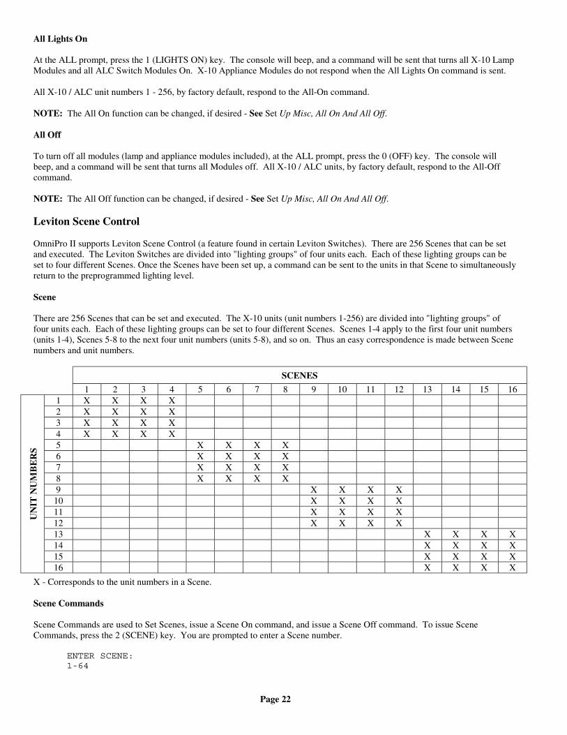
Page 22
All Lights On
At the ALL prompt, press the 1 (LIGHTS ON) key. The console will beep, and a command will be sent that turns all X-10 LampModules and all ALC Switch Modules On. X-10 Appliance Modules do not respond when the All Lights On command is sent.
All X-10 / ALC unit numbers 1 - 256, by factory default, respond to the All-On command.
NOTE: The All On function can be changed, if desired - See Set Up Misc, All On And All Off.
All Off
To turn off all modules (lamp and appliance modules included), at the ALL prompt, press the 0 (OFF) key. The console willbeep, and a command will be sent that turns all Modules off. All X-10 / ALC units, by factory default, respond to the All-Offcommand.
NOTE: The All Off function can be changed, if desired - See Set Up Misc, All On And All Off.
Leviton Scene Control
OmniPro II supports Leviton Scene Control (a feature found in certain Leviton Switches). There are 256 Scenes that can be setand executed. The Leviton Switches are divided into "lighting groups" of four units each. Each of these lighting groups can beset to four different Scenes. Once the Scenes have been set up, a command can be sent to the units in that Scene to simultaneouslyreturn to the preprogrammed lighting level.
Scene
There are 256 Scenes that can be set and executed. The X-10 units (unit numbers 1-256) are divided into "lighting groups" offour units each. Each of these lighting groups can be set to four different Scenes. Scenes 1-4 apply to the first four unit numbers(units 1-4), Scenes 5-8 to the next four unit numbers (units 5-8), and so on. Thus an easy correspondence is made between Scenenumbers and unit numbers.
SCENES
1 2 3 4 5 6 7 8 9 10 11 12 13 14 15 161 X X X X2 X X X X3 X X X X4 X X X X5 X X X X6 X X X X7 X X X X8 X X X X9 X X X X
10 X X X X11 X X X X12 X X X X13 X X X X14 X X X X15 X X X X
UN
IT N
UM
BE
RS
16 X X X X
X - Corresponds to the unit numbers in a Scene.
Scene Commands
Scene Commands are used to Set Scenes, issue a Scene On command, and issue a Scene Off command. To issue SceneCommands, press the 2 (SCENE) key. You are prompted to enter a Scene number.
ENTER SCENE:1-64
Page 23
Enter the Scene number (1-256) followed be the ' # ' key.
SCENE 10=OFF 1=ON 2=SET
Scene Set Command
The Scene Set command is used to set up Scenes for a lighting group. Set the desired lighting level for each of the units in thelighting group for the first Scene. The desired lighting level may be set manually at the switch, or by a command issued from thecontroller. After the desired lighting levels are set, press the 2 (SET) key to save the first Scene for that group. Commands aresent to each of the four units in that group to instruct each unit to save its current lighting level as the lighting level for the Scene.Repeat these steps to set up each of the remaining three Scenes for that lighting group.
Scene On Command
Once the Scenes have been set up, press the 1 (ON) key to command the four units in that Scene to return to the lighting level setby the Scene Set command for that Scene.
Scene Off Command
Once the Scenes have been sent, press the 0 (OFF) key to command the four units in that Scene to turn off.
Notes:
1. When sending Scene Commands, the controller must be configured to allow Extended Code transmissions on each HouseCode affected by a Scene.
2. The Scene Commands always apply to a group of four consecutive units, which are units 1-4, 5-8, 9-12, and 13-16 on aparticular house code. You must address the units accordingly so that the desired units fall into the appropriate lightinggroups.
3. The actual Extended Code Scene commands use a "group reference" that matches that sent by a Leviton Wall-MountedScene Controller set to the same address as the first unit in the lighting group. This allows wall-mounted controllers to beeasily used for manual Scene selection.
Buttons
A powerful feature of the OmniPro II is the ability to program Buttons. A Button (also known as macro) is a number on thekeypad that is programmed to execute a series of commands when it is pressed. Buttons are used to program functions that arespecific to your home and lifestyle.
Using a button, you can activate several commands at once. You can personalize 128 buttons with descriptive names. Thefollowing are some examples of programmed Buttons:
Leave for Work (Button 1):- turn off all lights- set thermostat to energy saving settings- arm the security system in the Away mode
Go to Bed (Button 2):- turn off all lights- dim outdoor lights 20% to extend bulb life and reduce consumption- arm security in Night mode
Dinner for Two (Button 3):- dim the dining and living room lights- turn on the porch light- turn off all the bedroom lights- dim the den light- turn on the stereo
Page 24
To activate a preprogrammed button, from the top-level display or from the main menu, press the 3 (BTTN) key on the consolekeypad. Select the button (macro) to be activated by using the arrow keys to scroll through a list of buttons, followed by ' # '.
For extra convenience, event buttons are automatically activated when you change security modes, or when security zones openand close. This powerful feature allows you to set your system up so that control functions are performed when you arm yoursecurity system (such as turning off all lights and setting back the HVAC system). Door contacts and motion detectors can beused to turn on lighting automatically, then turn it off a few minutes after the person has left, and then only if it's dark.
Temperature Control
Your OmniPro II can control temperatures of your heating and cooling system, monitor the outside temperature, and detect highand low temperatures in special situations. Other appliances can be controlled by temperature as well - such as a bathroom heateror a ceiling fan.
The temperature menu is used to control HAI Communicating Thermostats, Programmable Energy Saver Modules, andTemperature Sensors. The status of each of these may also be displayed on the console.
HAI Communicating Thermostats and the Programmable Energy Saver Module (PESM) provides energy savings, comfort, andconvenience by setting the HVAC system(s) to the proper temperature based on whether you are home, asleep, away, or vacation.The temperature can be reported as well as controlled over any telephone. A freeze alarm feature will cause a dial out if thetemperature falls below a preset level.
The HAI Communicating Thermostats are digital heating and cooling thermostats that can be controlled be the user and by remotecontrol. There are models for conventional single stage (gas or electric), heat pumps, and multi stage heating and coolingsystems. All models offer programmability, stand-alone operation, and robust communication to the OmniPro II system.
HAI RC-Series Thermostats
The following control actions are allowed for HAI Communicating Thermostats:
• Set heating setpoints• Set cooling setpoints• Set system mode (Off / Heat / Cool / Auto)• Set fan (On / Auto)• Turn hold On and Off
NOTE: Not all actions are applicable to every type of thermostat.
To enter the temperature menu, from the top-level display or from the main menu, press the 5 (TEMP) key on the console keypad.
You will be prompted with the first named temperature zone (i.e. Upstairs). The temperature zone can be specified by enteringthe temperature zone number followed by the ' # ' key, or by pressing the arrow keys to scroll through the list of temperaturezones. Press the ' # ' key when the desired temperature zone is shown.
Press the ' 0 ' key to select all HAI Thermostats. This is a simple way to broadcast the new Heat or Cool setting or change thesystem mode, fan mode, or hold mode of all HAI thermostats in your system. Temperature zones 1-64 are for HAI thermostats.
TEMPERATURE:ENTER TEMP ZONE 0=ALL ↓
After the ' # ' key is pressed, a menu appropriate for the type of temperature zone is shown. For Celsius temperatures, press the' # ' key prior to entering the temperature to make the number negative. The Celsius temperature may also be specified in 0.5degree steps, if three numeric digits are entered. The third digit adds a .5 to the first two digits, if it is anything other than zero.Enter a leading zero, if necessary.
For HAI heat/cool thermostats:
Upstairs1=MODE 2=HEAT 3=COOL ↓
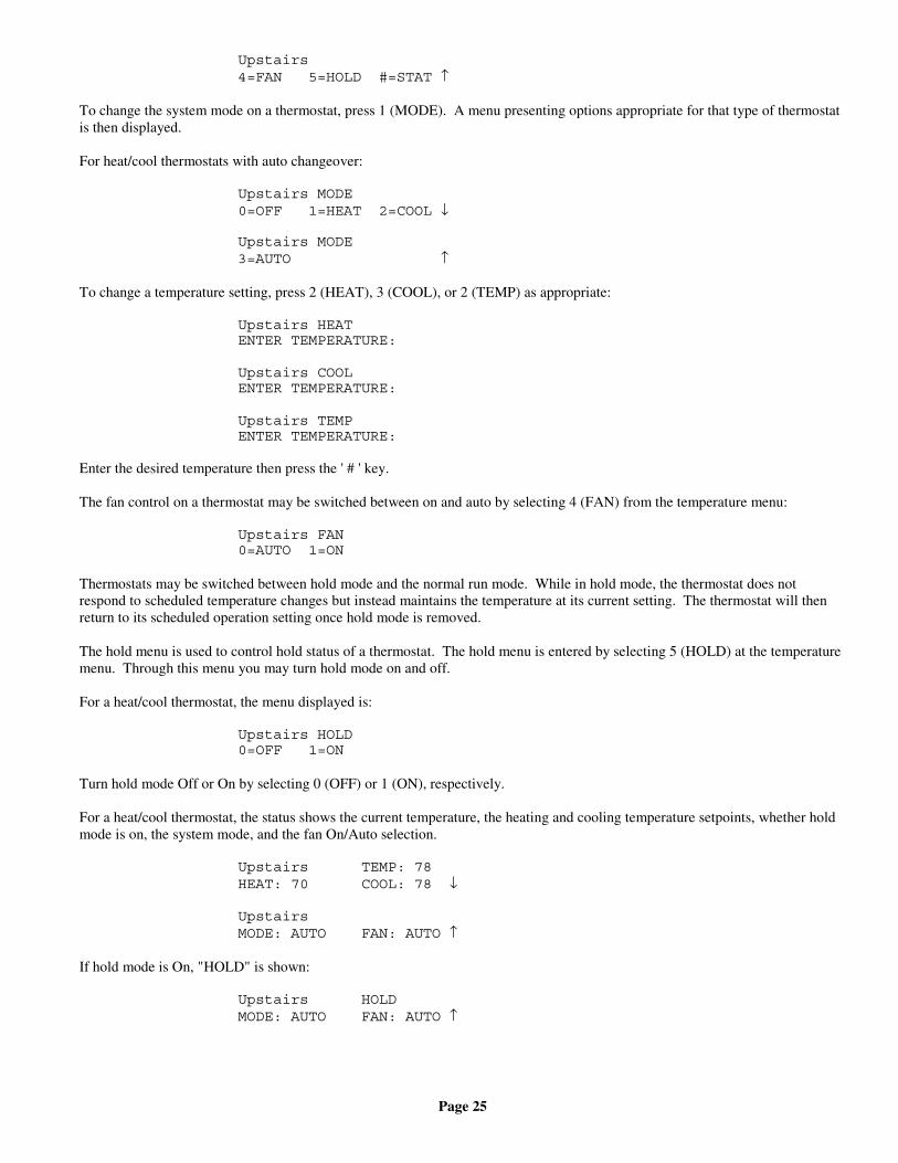
Page 25
Upstairs4=FAN 5=HOLD #=STAT ↑
To change the system mode on a thermostat, press 1 (MODE). A menu presenting options appropriate for that type of thermostatis then displayed.
For heat/cool thermostats with auto changeover:
Upstairs MODE0=OFF 1=HEAT 2=COOL ↓
Upstairs MODE3=AUTO ↑
To change a temperature setting, press 2 (HEAT), 3 (COOL), or 2 (TEMP) as appropriate:
Upstairs HEATENTER TEMPERATURE:
Upstairs COOLENTER TEMPERATURE:
Upstairs TEMPENTER TEMPERATURE:
Enter the desired temperature then press the ' # ' key.
The fan control on a thermostat may be switched between on and auto by selecting 4 (FAN) from the temperature menu:
Upstairs FAN0=AUTO 1=ON
Thermostats may be switched between hold mode and the normal run mode. While in hold mode, the thermostat does notrespond to scheduled temperature changes but instead maintains the temperature at its current setting. The thermostat will thenreturn to its scheduled operation setting once hold mode is removed.
The hold menu is used to control hold status of a thermostat. The hold menu is entered by selecting 5 (HOLD) at the temperaturemenu. Through this menu you may turn hold mode on and off.
For a heat/cool thermostat, the menu displayed is:
Upstairs HOLD0=OFF 1=ON
Turn hold mode Off or On by selecting 0 (OFF) or 1 (ON), respectively.
For a heat/cool thermostat, the status shows the current temperature, the heating and cooling temperature setpoints, whether holdmode is on, the system mode, and the fan On/Auto selection.
Upstairs TEMP: 78HEAT: 70 COOL: 78 ↓
UpstairsMODE: AUTO FAN: AUTO ↑
If hold mode is On, "HOLD" is shown:
Upstairs HOLDMODE: AUTO FAN: AUTO ↑
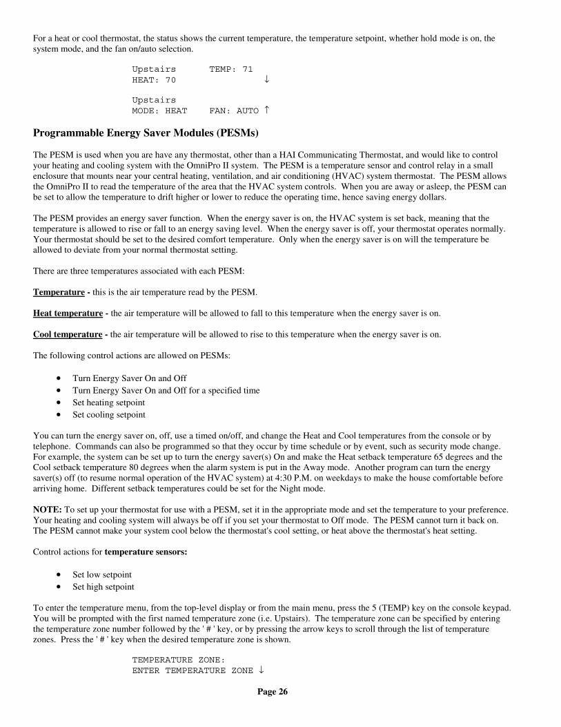
Page 26
For a heat or cool thermostat, the status shows the current temperature, the temperature setpoint, whether hold mode is on, thesystem mode, and the fan on/auto selection.
Upstairs TEMP: 71HEAT: 70 ↓
UpstairsMODE: HEAT FAN: AUTO ↑
Programmable Energy Saver Modules (PESMs)
The PESM is used when you are have any thermostat, other than a HAI Communicating Thermostat, and would like to controlyour heating and cooling system with the OmniPro II system. The PESM is a temperature sensor and control relay in a smallenclosure that mounts near your central heating, ventilation, and air conditioning (HVAC) system thermostat. The PESM allowsthe OmniPro II to read the temperature of the area that the HVAC system controls. When you are away or asleep, the PESM canbe set to allow the temperature to drift higher or lower to reduce the operating time, hence saving energy dollars.
The PESM provides an energy saver function. When the energy saver is on, the HVAC system is set back, meaning that thetemperature is allowed to rise or fall to an energy saving level. When the energy saver is off, your thermostat operates normally.Your thermostat should be set to the desired comfort temperature. Only when the energy saver is on will the temperature beallowed to deviate from your normal thermostat setting.
There are three temperatures associated with each PESM:
Temperature - this is the air temperature read by the PESM.
Heat temperature - the air temperature will be allowed to fall to this temperature when the energy saver is on.
Cool temperature - the air temperature will be allowed to rise to this temperature when the energy saver is on.
The following control actions are allowed on PESMs:
• Turn Energy Saver On and Off• Turn Energy Saver On and Off for a specified time• Set heating setpoint• Set cooling setpoint
You can turn the energy saver on, off, use a timed on/off, and change the Heat and Cool temperatures from the console or bytelephone. Commands can also be programmed so that they occur by time schedule or by event, such as security mode change.For example, the system can be set up to turn the energy saver(s) On and make the Heat setback temperature 65 degrees and theCool setback temperature 80 degrees when the alarm system is put in the Away mode. Another program can turn the energysaver(s) off (to resume normal operation of the HVAC system) at 4:30 P.M. on weekdays to make the house comfortable beforearriving home. Different setback temperatures could be set for the Night mode.
NOTE: To set up your thermostat for use with a PESM, set it in the appropriate mode and set the temperature to your preference.Your heating and cooling system will always be off if you set your thermostat to Off mode. The PESM cannot turn it back on.The PESM cannot make your system cool below the thermostat's cool setting, or heat above the thermostat's heat setting.
Control actions for temperature sensors:
• Set low setpoint• Set high setpoint
To enter the temperature menu, from the top-level display or from the main menu, press the 5 (TEMP) key on the console keypad.You will be prompted with the first named temperature zone (i.e. Upstairs). The temperature zone can be specified by enteringthe temperature zone number followed by the ' # ' key, or by pressing the arrow keys to scroll through the list of temperaturezones. Press the ' # ' key when the desired temperature zone is shown.
TEMPERATURE ZONE:ENTER TEMPERATURE ZONE ↓
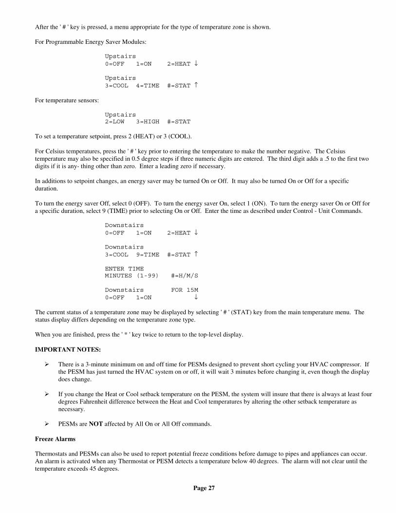
Page 27
After the ' # ' key is pressed, a menu appropriate for the type of temperature zone is shown.
For Programmable Energy Saver Modules:
Upstairs0=OFF 1=ON 2=HEAT ↓
Upstairs3=COOL 4=TIME #=STAT ↑
For temperature sensors:
Upstairs2=LOW 3=HIGH #=STAT
To set a temperature setpoint, press 2 (HEAT) or 3 (COOL).
For Celsius temperatures, press the ' # ' key prior to entering the temperature to make the number negative. The Celsiustemperature may also be specified in 0.5 degree steps if three numeric digits are entered. The third digit adds a .5 to the first twodigits if it is any- thing other than zero. Enter a leading zero if necessary.
In additions to setpoint changes, an energy saver may be turned On or Off. It may also be turned On or Off for a specificduration.
To turn the energy saver Off, select 0 (OFF). To turn the energy saver On, select 1 (ON). To turn the energy saver On or Off fora specific duration, select 9 (TIME) prior to selecting On or Off. Enter the time as described under Control - Unit Commands.
Downstairs0=OFF 1=ON 2=HEAT ↓
Downstairs3=COOL 9=TIME #=STAT ↑
ENTER TIMEMINUTES (1-99) #=H/M/S
Downstairs FOR 15M0=OFF 1=ON ↓
The current status of a temperature zone may be displayed by selecting ' # ' (STAT) key from the main temperature menu. Thestatus display differs depending on the temperature zone type.
When you are finished, press the ' * ' key twice to return to the top-level display.
IMPORTANT NOTES:
There is a 3-minute minimum on and off time for PESMs designed to prevent short cycling your HVAC compressor. Ifthe PESM has just turned the HVAC system on or off, it will wait 3 minutes before changing it, even though the displaydoes change.
If you change the Heat or Cool setback temperature on the PESM, the system will insure that there is always at least fourdegrees Fahrenheit difference between the Heat and Cool temperatures by altering the other setback temperature asnecessary.
PESMs are NOT affected by All On or All Off commands.
Freeze Alarms
Thermostats and PESMs can also be used to report potential freeze conditions before damage to pipes and appliances can occur.An alarm is activated when any Thermostat or PESM detects a temperature below 40 degrees. The alarm will not clear until thetemperature exceeds 45 degrees.
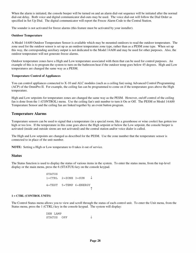
Page 28
When the alarm is initiated, the console beeper will be turned on and an alarm dial-out sequence will be initiated after the normaldial-out delay. Both voice and digital communicator dial-outs may be used. The voice dial-out will follow the Dial Order asspecified in Set Up Dial. The digital communicator will report the Freeze Alarm Code to the Central Station.
The sounder is not activated for freeze alarms (this feature must be activated by your installer).
Outdoor Temperature
A Model 14A00 Outdoor Temperature Sensor is available which may be mounted outdoors to read the outdoor temperature. Thezone used for the outdoor sensor is set up as an outdoor temperature zone type, rather than as a PESM zone type. When set upthis way, the corresponding auxiliary output is not dedicated to the Model 14A00 and may be used for other purposes. Also, theoutdoor temperature will not generate freeze alarms.
Outdoor temperature zones have a High and Low temperature associated with them that can be used for control purposes. Anexample of this is to program the system to turn on the bathroom heat if the outdoor temp goes below 45 degrees. High and Lowtemperatures are changed the same way as a PESM.
Temperature Control of Appliances
You can control appliances connected to X-10 and ALC modules (such as a ceiling fan) using Advanced Control Programming(ACP) of the OmniPro II. For example, the ceiling fan can be programmed to come on if the temperature goes above the Hightemperature.
High and Low setpoints for temperature zones are changed the same way as the PESM. However, on/off control of the ceilingfan is done from the 1 (CONTROL) menu. Use the ceiling fan's unit number to turn it On or Off. The PESM or Model 14A00Temperature Sensor and the ceiling fan are linked together by an event button program.
Temperature Alarms
Temperature sensors can be used to signal that a temperature (in a special room, like a greenhouse or wine cooler) has gotten toohigh or too low. If the temperature in this zone goes above the High setpoint or below the Low setpoint, the console beeper isactivated (inside and outside sirens are not activated) and the central station and/or voice dialer is called.
The High and Low setpoints are changed as described for the PESM. Use the zone number that the temperature sensor isconnected to in place of the unit number.
NOTE: Setting a High or Low temperature to 0 takes it out of service.
Status
The Status function is used to display the status of various items in the system. To enter the status menu, from the top-leveldisplay or the main menu, press the 6 (STATUS) key on the console keypad.
STATUS1=CTRL 2=ZONE 3=SUN ↓
4=TEST 5=TEMP 6=ENERGY ↑
1 = CTRL (CONTROL UNITS)
The Control Status menu allows you to view and scroll through the status of each control unit. To enter the Unit menu, from theStatus menu, press the 1 (CTRL) key in the console keypad. The system will display:
DEN LAMPSTATUS OFF ↓
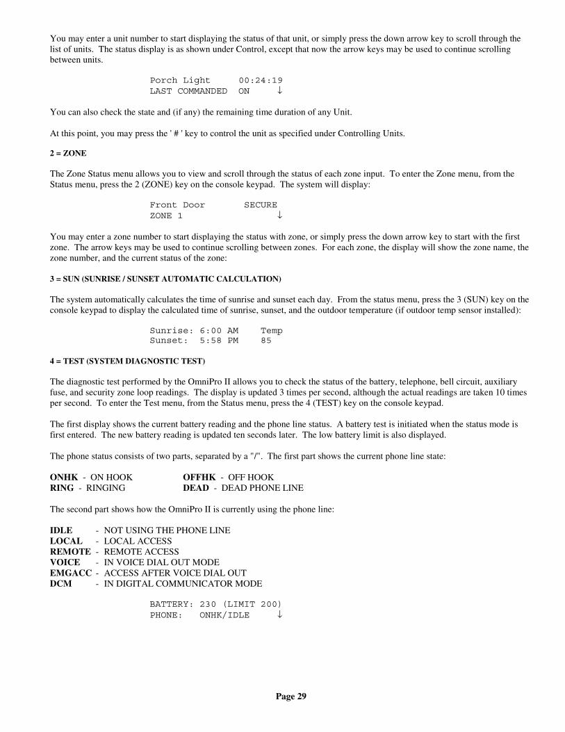
Page 29
You may enter a unit number to start displaying the status of that unit, or simply press the down arrow key to scroll through thelist of units. The status display is as shown under Control, except that now the arrow keys may be used to continue scrollingbetween units.
Porch Light 00:24:19LAST COMMANDED ON ↓
You can also check the state and (if any) the remaining time duration of any Unit.
At this point, you may press the ' # ' key to control the unit as specified under Controlling Units.
2 = ZONE
The Zone Status menu allows you to view and scroll through the status of each zone input. To enter the Zone menu, from theStatus menu, press the 2 (ZONE) key on the console keypad. The system will display:
Front Door SECUREZONE 1 ↓
You may enter a zone number to start displaying the status with zone, or simply press the down arrow key to start with the firstzone. The arrow keys may be used to continue scrolling between zones. For each zone, the display will show the zone name, thezone number, and the current status of the zone:
3 = SUN (SUNRISE / SUNSET AUTOMATIC CALCULATION)
The system automatically calculates the time of sunrise and sunset each day. From the status menu, press the 3 (SUN) key on theconsole keypad to display the calculated time of sunrise, sunset, and the outdoor temperature (if outdoor temp sensor installed):
Sunrise: 6:00 AM TempSunset: 5:58 PM 85
4 = TEST (SYSTEM DIAGNOSTIC TEST)
The diagnostic test performed by the OmniPro II allows you to check the status of the battery, telephone, bell circuit, auxiliaryfuse, and security zone loop readings. The display is updated 3 times per second, although the actual readings are taken 10 timesper second. To enter the Test menu, from the Status menu, press the 4 (TEST) key on the console keypad.
The first display shows the current battery reading and the phone line status. A battery test is initiated when the status mode isfirst entered. The new battery reading is updated ten seconds later. The low battery limit is also displayed.
The phone status consists of two parts, separated by a "/". The first part shows the current phone line state:
ONHK - ON HOOK OFFHK - OFF HOOK RING - RINGING DEAD - DEAD PHONE LINE
The second part shows how the OmniPro II is currently using the phone line:
IDLE - NOT USING THE PHONE LINELOCAL - LOCAL ACCESSREMOTE - REMOTE ACCESSVOICE - IN VOICE DIAL OUT MODEEMGACC - ACCESS AFTER VOICE DIAL OUTDCM - IN DIGITAL COMMUNICATOR MODE
BATTERY: 230 (LIMIT 200)PHONE: ONHK/IDLE ↓
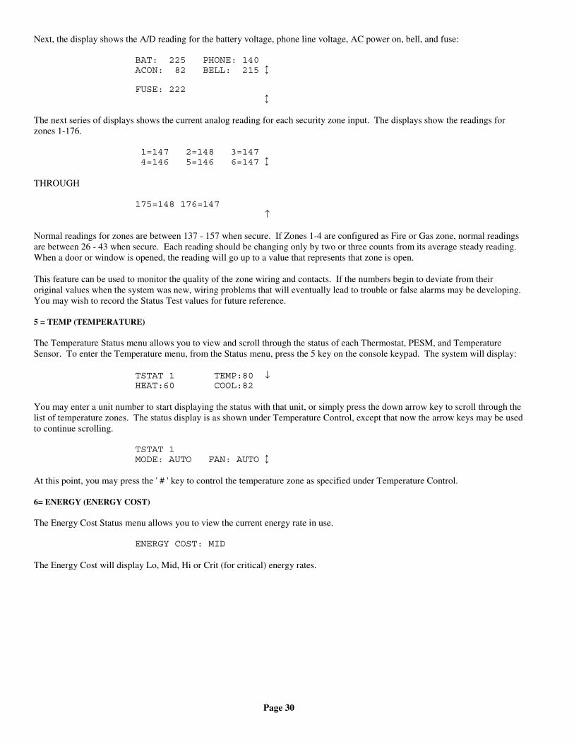
Page 30
Next, the display shows the A/D reading for the battery voltage, phone line voltage, AC power on, bell, and fuse:
BAT: 225 PHONE: 140ACON: 82 BELL: 215 ↕
FUSE: 222 ↕
The next series of displays shows the current analog reading for each security zone input. The displays show the readings forzones 1-176.
1=147 2=148 3=147 4=146 5=146 6=147 ↕
THROUGH
175=148 176=147 ↑
Normal readings for zones are between 137 - 157 when secure. If Zones 1-4 are configured as Fire or Gas zone, normal readingsare between 26 - 43 when secure. Each reading should be changing only by two or three counts from its average steady reading.When a door or window is opened, the reading will go up to a value that represents that zone is open.
This feature can be used to monitor the quality of the zone wiring and contacts. If the numbers begin to deviate from theiroriginal values when the system was new, wiring problems that will eventually lead to trouble or false alarms may be developing.You may wish to record the Status Test values for future reference.
5 = TEMP (TEMPERATURE)
The Temperature Status menu allows you to view and scroll through the status of each Thermostat, PESM, and TemperatureSensor. To enter the Temperature menu, from the Status menu, press the 5 key on the console keypad. The system will display:
TSTAT 1 TEMP:80 ↓HEAT:60 COOL:82
You may enter a unit number to start displaying the status with that unit, or simply press the down arrow key to scroll through thelist of temperature zones. The status display is as shown under Temperature Control, except that now the arrow keys may be usedto continue scrolling.
TSTAT 1MODE: AUTO FAN: AUTO ↕
At this point, you may press the ' # ' key to control the temperature zone as specified under Temperature Control.
6= ENERGY (ENERGY COST)
The Energy Cost Status menu allows you to view the current energy rate in use.
ENERGY COST: MID
The Energy Cost will display Lo, Mid, Hi or Crit (for critical) energy rates.
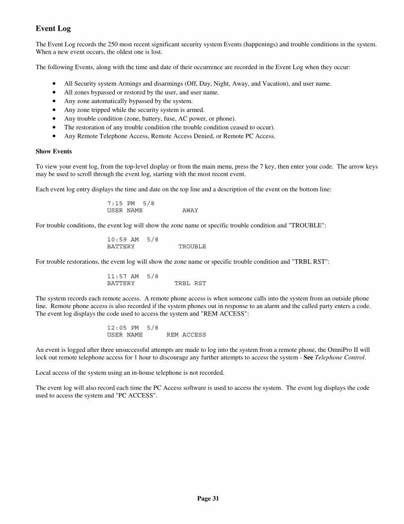
Page 31
Event Log
The Event Log records the 250 most recent significant security system Events (happenings) and trouble conditions in the system.When a new event occurs, the oldest one is lost.
The following Events, along with the time and date of their occurrence are recorded in the Event Log when they occur:
• All Security system Armings and disarmings (Off, Day, Night, Away, and Vacation), and user name.• All zones bypassed or restored by the user, and user name.• Any zone automatically bypassed by the system.• Any zone tripped while the security system is armed.• Any trouble condition (zone, battery, fuse, AC power, or phone).• The restoration of any trouble condition (the trouble condition ceased to occur).• Any Remote Telephone Access, Remote Access Denied, or Remote PC Access.
Show Events
To view your event log, from the top-level display or from the main menu, press the 7 key, then enter your code. The arrow keysmay be used to scroll through the event log, starting with the most recent event.
Each event log entry displays the time and date on the top line and a description of the event on the bottom line:
7:15 PM 5/8USER NAME AWAY
For trouble conditions, the event log will show the zone name or specific trouble condition and "TROUBLE":
10:59 AM 5/8BATTERY TROUBLE
For trouble restorations, the event log will show the zone name or specific trouble condition and "TRBL RST":
11:57 AM 5/8BATTERY TRBL RST
The system records each remote access. A remote phone access is when someone calls into the system from an outside phoneline. Remote phone access is also recorded if the system phones out in response to an alarm and the called party enters a code.The event log displays the code used to access the system and "REM ACCESS":
12:05 PM 5/8USER NAME REM ACCESS
An event is logged after three unsuccessful attempts are made to log into the system from a remote phone, the OmniPro II willlock out remote telephone access for 1 hour to discourage any further attempts to access the system - See Telephone Control.
Local access of the system using an in-house telephone is not recorded.
The event log will also record each time the PC Access software is used to access the system. The event log displays the codeused to access the system and "PC ACCESS".
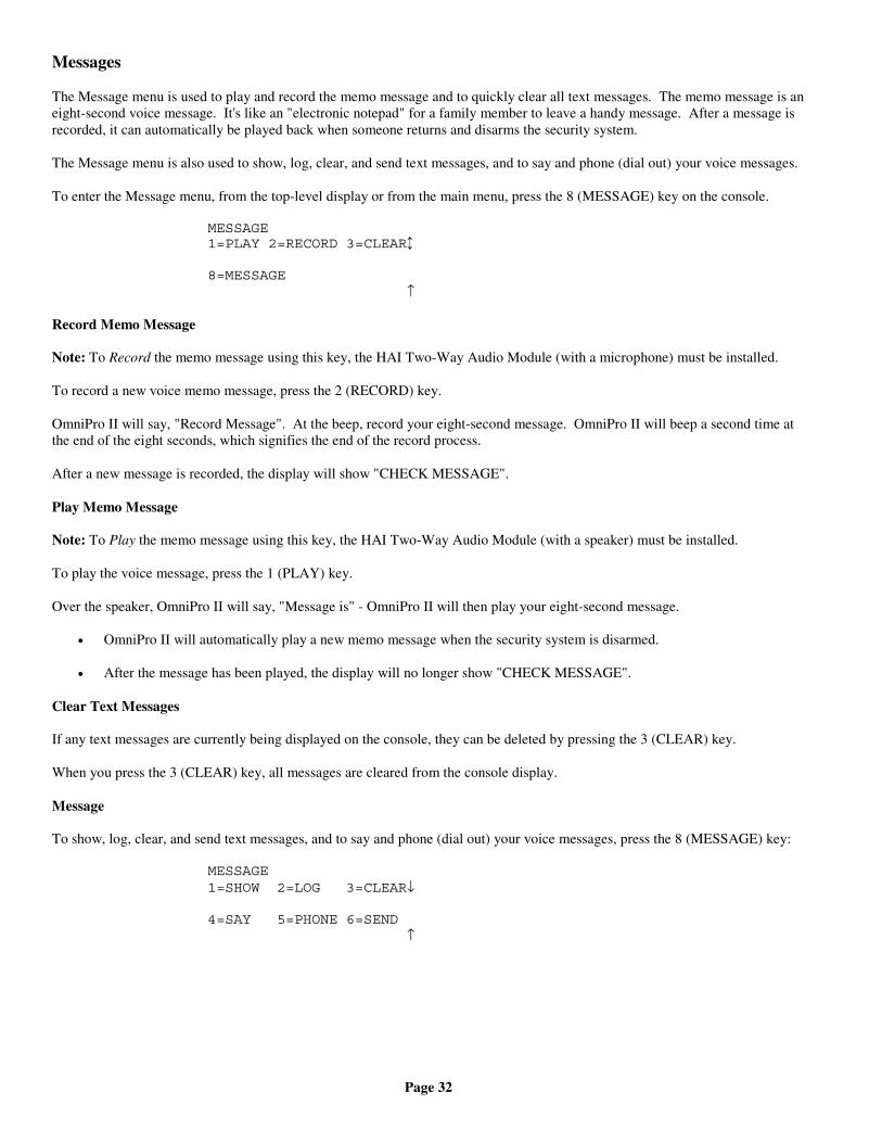
Page 32
Messages
The Message menu is used to play and record the memo message and to quickly clear all text messages. The memo message is aneight-second voice message. It's like an "electronic notepad" for a family member to leave a handy message. After a message isrecorded, it can automatically be played back when someone returns and disarms the security system.
The Message menu is also used to show, log, clear, and send text messages, and to say and phone (dial out) your voice messages.
To enter the Message menu, from the top-level display or from the main menu, press the 8 (MESSAGE) key on the console.
MESSAGE1=PLAY 2=RECORD 3=CLEAR↕
8=MESSAGE ↑
Record Memo Message
Note: To Record the memo message using this key, the HAI Two-Way Audio Module (with a microphone) must be installed.
To record a new voice memo message, press the 2 (RECORD) key.
OmniPro II will say, "Record Message". At the beep, record your eight-second message. OmniPro II will beep a second time atthe end of the eight seconds, which signifies the end of the record process.
After a new message is recorded, the display will show "CHECK MESSAGE".
Play Memo Message
Note: To Play the memo message using this key, the HAI Two-Way Audio Module (with a speaker) must be installed.
To play the voice message, press the 1 (PLAY) key.
Over the speaker, OmniPro II will say, "Message is" - OmniPro II will then play your eight-second message.
• OmniPro II will automatically play a new memo message when the security system is disarmed.
• After the message has been played, the display will no longer show "CHECK MESSAGE".
Clear Text Messages
If any text messages are currently being displayed on the console, they can be deleted by pressing the 3 (CLEAR) key.
When you press the 3 (CLEAR) key, all messages are cleared from the console display.
Message
To show, log, clear, and send text messages, and to say and phone (dial out) your voice messages, press the 8 (MESSAGE) key:
MESSAGE1=SHOW 2=LOG 3=CLEAR↓
4=SAY 5=PHONE 6=SEND ↑
Page 33
Show Message
The 1 (SHOW) key allows you to display the selected text message(s) on the console's top-level display. This can be a helpfulreminder of special events and occasions.
TRASH NIGHTENTER MESSAGE ↓
You may enter the message number followed by the ' # ' key to display that message, or simply press the down arrow key to scrollthrough a list of messages. Press the ' # ' key to display the selected message:
Thu Oct 04, 01 4:06 PMTRASH NIGHT
When the message is displayed, the console will beep 4 times and the console LED will flash continuously. You may press the' * ' key to acknowledge seeing the message. This will cause the LED to stop flashing, however, the message will remain on thedisplay until it is manually cleared, or cleared by a program.
Log Message
The 2 (LOG) key allows you to store the selected text message(s) in the Event Log. This can be a helpful to keep track of thetimes and dates of events and occurrences.
You may enter the message number followed by the ' # ' key to log that message, or simply press the down arrow key to scrollthrough a list of messages. Press the ' # ' key to log the selected message.
Clear Message
The 3 (CLEAR) key allows you to clear the selected text message, or all text messages from the console's display.
TRASH NIGHTENTER MESSAGE 0=ALL ↓
You may enter the message number followed by the ' # ' key to clear that message, or simply press the down arrow key to scrollthrough a list of messages. Press the ' # ' key to clear the selected message, or press 0, then ' # ' to clear all messages.
Say Message
Note: To Say a message, the HAI Two-Way Audio Module (with a speaker) must be installed.
The 4 (SAY) key allows the controller to say the selected voice message over a speaker. This voice message can be an audiblereminder of special events and occasions.
You may enter the message number followed by the ' # ' key to say that message, or simply press the down arrow key to scrollthrough a list of messages. Press the ' # ' key to say the selected message.
Phone Message
The 5 (PHONE) key allows the controller to call the selected phone number and say the selected voice message.
PHONE NUMBER:1-8
Select a phone number (1-8) from the dial menu, then press ' # ':
SECURITY OFFENTER MESSAGE ↓
You may enter the message number followed by the ' # ' key, or simply press the down arrow key to scroll through a list ofmessages. Press the ' # ' key to dial the number and say the selected voice message.
Page 34
Send Message (Pro-Link)
The 6 (SEND) key allows you to send any of the text messages through the Pro-Link serial port. You are first prompted tospecify the desired serial port.
SERIAL PORT:1-4
The built-in serial ports (J1-J3) on the controller are assigned to Serial Port 1 - Serial Port 3, respectively. Serial port 4 is a SerialInterface Module connected to the Expansion port on the controller.
Next, select the message to be sent. You may enter the message number followed by the ' # ' key to send that message, or simplypress the down arrow key to scroll through a list of messages. Press the ' # ' key to send the selected message:
MSGNAMEENTER MESSAGE: ↓
The message is sent out through the specified Pro-Link port exactly as the message was entered in Setup | Names | Message.
Carriage returns and line feed characters are not automatically appended to the end. To send ASCII control as part of themessage, use the caret "^" character in the message. This character specifics that the next character is to be interpreted as anASCII control character, such as "^M" to represent a carriage return.
Other useful sequences would be "^J" for a line feed character and "^G" for a bell character. To include an actual "^" character inthe message, enter it twice as in "^^".
Each message can be up to 15 characters long. To send a longer message, simply program two messages to be sent one after theother.
Pro-Link also has the capability to monitor the serial port for incoming text messages. When a text message is received, Pro-Linksearches through all 128 messages for a matching message. If one is found, the Program Command (macro) corresponding to thematching message is activated.
When receiving an ASCII message that is over 15 characters, OmniPro II only processes the last 15 characters of the message.
Pro-Link determines that a message has been received when:
• One or more characters have been received followed by 100 ms of silence• One or more characters followed by a carriage return character are received• One or more characters followed by a line feed character are received
It is not necessary to enter the terminating carriage return or line feed character as part of the message name.
Page 35
TELEPHONE CONTROL
Telephone Interface
Your OmniPro II is equipped with a built-in telephone response feature that allows you to control and access the status of yoursystem from any Touch-Tone phone.
The OmniPro II actually talks to you using a digital recording of an actual human voice, so the sound is incredibly life like. Yousend commands to the OmniPro II using the keys of your Touch-Tone telephone. There are no tapes, discs, or other moving partsassociated with the speech and control features, so there is no maintenance or parts to wear out.
Only Touch-Tone phones will work with the OmniPro II. Some phones have switches that allow you to select Pulse or Tone. Setthem to Tone to work with the OmniPro II.
NOTE: There are two keys on your Touch-Tone telephone that are special. The ' # ' key (pound key, to the right of the zero),and the ' * ' key (star key, to the left of the zero). You will be using these keys.
In-House Phones
Each time you pick up your telephone at home, the OmniPro II will also pick up the line and listen for a # (pound) key. IfOmniPro II does not hear the # key within 5 seconds, it hangs up and does not listen in again until the next time you pick up yourphone. If the OmniPro II hears any key other than the # key while it is listening in, it disconnects itself immediately.
If the OmniPro II does hear the # key within 3 seconds of your picking up the receiver, it disconnects your phones from the phonecompany lines and connects your phones to itself, and begins talking to you. When you hang up, your phones are immediatelyreconnected to the phone company.
You will hear a slight click on your phone when the OmniPro II picks up or hangs up. This is normal. To access your OmniProII from an in-house phone: Pick up the receiver of any Touch-Tone phone in your house. Pause for just a moment (about asecond), then press the # key on the phone.
You will hear the voice read the menu, which tells you what commands are available over the telephone.
NOTE: If your system is in High Security Mode, you must also enter your code following the # key - See High Security Mode.In UL Listed Installations, High Security Mode is enabled.
If the alarm system is tripped, the in-house phones will be disconnected when the OmniPro II begins to dial out, to preclude aburglar from jamming the line by shorting out an in-house phone. In this case, you will have to turn the system off at the console.
Remote Phones
You may call your system from any Touch Tone phone and "talk" to your OmniPro II, exactly as if you were at home, except thatyou must enter your code (Master or Manager) to gain access to the OmniPro II.
To call your system from any touch tone phone, call your number. After 8 rings (or whatever you have "Rings Before Answer"set to) your OmniPro II will answer and "beep" - See Set Up Dial. Press the digits of your code on the phone. The first digit mustbe pressed within 3 seconds of the beep. You will hear the menu.
If you hear three beeps after entering the code, you have entered the wrong code. Try again. If you make a mistake whileentering the code, press the # key and then enter the code again. You only have three tries to enter a valid code.
A successful remote access is logged in the event log as a Remote Phone Access, along with the time, date of its occurrence, andthe code number used.
There are a number of setup items that control what you can do from a remote phone when you or anyone else calls into yourhome - See Set Up, Dial.
Page 36
Phone Access Denied - Remote Lockout
The OmniPro II has a remote lockout feature to discourage youngsters (and adults who act that way) from trying to access yoursystem. If four invalid codes are entered, the system will hang up and a one-hour lockout period will begin. During the lockoutperiod, the OmniPro II will not answer a call after any number of rings, which should discourage the caller.
If a lockout occurs, the event Phone Access Denied is entered into the event log, along with the time and date of its occurrence.
The one-hour lockout does not apply to in-house phones. The lockout is cleared immediately if the OmniPro II is accessed usingan in-house phone.
Alternate Method
The OmniPro II has an alternate access method that may be more effective, especially when calling long distance.
1. Call the system and allow the phone to ring once or twice.
2. Hang up.
3. Wait about 10 seconds, but within 60 seconds, call the system again. It will answer on the first ring and beep.
4. Enter your code.
Main Menu
Once you have successfully logged into your OmniPro II, it will read you a menu of commands, as follows:
WELCOME TO OMNIPRO [AREA 1] PLEASE CHOOSE:
1: CONTROL2: SECURITY3: BUTTON4: ALL5: TEMPERATURE6: STATUS7: EVENT8: PHONE9: GOOD-BYE*: CANCEL0: REPEAT
This means that you press '1' for Control functions, '2' for Security, '3' for Button, etc. Pressing one of the keys on the phone willmove you to another menu. These menus are the same as the menus on the console. Words in brackets [ ] are only spoken if thatfeature is in use.
You do not have to wait for the OmniPro II to finish talking. Once you are familiar with the menus, you can simply punch thenumbers on the phone without waiting. Whenever you press a number, the OmniPro II stops talking and goes on to the functionthat you have selected. If you press a key that is not on the current menu, you will hear 3 beeps and the menu will be repeated.
So that the OmniPro II does not tie up your phone, there is a 10 to 15 second time-out that starts after the OmniPro II stopstalking. If it does not hear any numbers from your phone in 10 to 15 seconds after it stops talking, the OmniPro II will hang up.If you are on a remote phone and the OmniPro II hangs up, you must call the OmniPro II again. If you are on an in-house phone,hang up, wait a few seconds, then pick up and press the # key.
To hear the main menu again, press 0 on your phone. To cancel an operation, press ' * ' for Cancel. You will hear "CANCEL"and one beep for a cancel operation.
If you make a mistake, you will hear 3 beeps, then the OmniPro II will re-read whichever menu you are in.
Page 37
1 - Control
Press 1 from the MAIN MENU to get to the CONTROL menu.
If voice descriptions have been programmed, after a three-second delay, the system will begin reading from the list of units(OmniPro II will say the unit number then its description). The OmniPro II will read three units, then say,
"PRESS POUND TO CONTINUE."
If the ' # ' key is pressed, OmniPro II will read the next three unit numbers and descriptions (if programmed).
2 - Security
Press 2 from the MAIN MENU to get to the SECURITY menu.
From the Security menu you can arm your system (Day, Night, Away, Vacation, Day Instant, and Night Delayed), disarm yousystem, bypass and restore zones, and go to a different area.
When bypassing and restoring a zone, if voice descriptions have been programmed, after a three-second delay, the system willbegin reading from the list of zones. If the ' # ' key is pressed, OmniPro II will read the next three descriptions (if programmed).
GOTO Area
Press the # key to GOTO a different area. OmniPro II will say:
"GOTO AREA: ENTER AREA THEN #." "ENTER CODE, *: CANCEL""WELCOME TO OMNIPRO II, AREA 2."
3 - Button
Press 3 from the MAIN MENU to get to the BUTTON menu.
If button voice descriptions have been programmed, after a three-second delay, the system will begin reading from the list ofbuttons (OmniPro II will say the button number then its description).
User buttons 1 - 128 are available from the phone, for the current area.
4 - All
Press 4 from the MAIN MENU to get to the ALL menu.
"ALL: PLEASE CHOOSE:" 0: ALL OFF 1: ALL ON
2: LIGHT SETTING (Leviton Scene)
5 - Temperature
Press 5 from the MAIN MENU to get to the TEMPERATURE menu. The OmniPro II will say,
"TEMPERATURE: ENTER TEMPERATURE NUMBER, THEN POUND."
After a three second delay, the system will begin reading from the list of Thermostats and Energy Savers (if voice descriptionshave been programmed, OmniPro II will say the temperature zone then its description). The OmniPro II will read threetemperature zones, then say,
"PRESS POUND TO CONTINUE."
If the ' # ' key is pressed, OmniPro II will read the next three temperature zones and descriptions (if programmed).
Page 38
Press the temperature zone you wish to control, then press #.
Press the ' 0 ' key to select all HAI Thermostats. This is a simple way to broadcast the new Heat or Cool setting or change thesystem mode, fan mode, or hold mode of all HAI thermostats in your system.
When an HAI Communicating Thermostat is entered:
"THERMOSTAT 1 - THERMOSTAT 1 - TEMPERATURE IS (TEMP)."
"PLEASE CHOOSE: 1: MODE 2: HEAT SETTING 3: COOL SETTING 4: FAN 5: HOLD #: STATUS *: CANCEL
- If the # (STATUS) key is selected, OmniPro II will read the current status of the thermostat. For instance:
"TEMPERATURE IS (80), HEAT SETTING IS (60), COOL SETTING IS (75), MODE IS (COOL), FAN IS (AUTO), HOLD IS (OFF)."
When a Programmable Energy Saver (PESM) is entered:
"ZONE 9 ENERGY SAVER - ENERGY SAVER IS (ON/OFF). TEMPERATURE IS (TEMP)."
"PLEASE CHOOSE: 0: OFF 1: ON 2: HEAT SETTING 3: COOL SETTING 9: TIMED #: STATUS *: CANCEL
- If the # (STATUS) key is selected, OmniPro II will read the current status of the PESM. For instance:
"ENERGY SAVER IS (ON/OFF): TEMPERATURE IS (80), HEAT SETTING IS (60), COOL SETTING IS (75)."
6 - Status
Press 6 from the MAIN MENU to get to the STATUS menu.
From the Status menu, OmniPro II will report the Security Mode (for the current Area).
If all zones are secure and there are no troubles with the system, OmniPro II reports "System OK".
If any zones are currently not ready, in trouble, or bypassed, OmniPro II will report the current status of those zones. Any systemtroubles are also reported.
Finally, OmniPro II will report the current Outdoor Temperature (if part of the system) and the current time and date.
7 - Events
Press 7 from the MAIN MENU to get to the EVENT menu.
The OmniPro II will read the 3 latest events. Press the ' 7 ' key for OmniPro II to read 3 more events, or ' * ' to cancel.
Page 39
8 - Message
This command allows you to record and verify the voice memo message, allows you to record and play custom messages(phrases), and allows you to record and verify your address. If an optional HAI Two-Way Audio Module is being used, thiscommand also allows paging and listening to the premises.
Press 8 from the MAIN MENU to get to the MESSAGE menu.
"MESSAGE - PLEASE CHOOSE: 1 PLAY MESSAGE, 2 RECORD MESSAGE, 3 INTERIOR, 6 PLAY PHRASE, 7 RECORD PHRASE, 8 PLAY ADDRESS, 9 RECORD ADDRESS, *: CANCEL."
To play the current address, press the 8 key.
Playing and Recording a Message
To play the current message, press the 1 key.
"MESSAGE IS: (OMNIPRO II PLAYS MESSAGE)."
Note: When OmniPro II is playing the message or the address, it does not listen for Touch-Tones.
To record the memo message, press the 2 key.
"RECORD MESSAGE - [BEEP]
At the [BEEP], record your message...
At the second [BEEP]:
"MESSAGE IS: (OMNIPRO II PLAYS MESSAGE)."
Paging and Listening
When the HAI Two-Way Audio Module is being used:
To talk or listen to the premises, press the 3 key.
"PLEASE CHOOSE: 2 TALK, 8 LISTEN, *: CANCEL."
• If no key is pressed, OmniPro II will automatically switch to listen mode.
To talk to someone at the premises, press the 2 key.
To listen to the premises, press the 8 key.
• You cannot talk to anyone on premises in listen mode and you cannot listen to the premises while in the talk mode.
Playing and Recording a Custom Phrase
When you can't find a word you need to complete a voice description or voice message, you have to ability to record a customphrase in OmniPro II. This phrase can then be used as part of your voice description and spoken over the telephone along withthe item number that is normally spoken. It can also be part of your voice descriptions for a message that is spoken over aspeaker in your home or business.
Phrases 1-32 are unique two-second phrases. Phrases 33-48 are four-second phrases that are made up of 2 two-second phrases.Phrases 49-56 are eight-second phrases that are made up of 4 two-second phrases. Phrases 57-60 are sixteen-second phrases thatare made up of 8 two-second phrases.
For a complete list of Phrases and Voice Descriptions, including a complete description of Custom Phrases - See Appendix CVoice Description Codes and Notes on Custom Phrases in this manual.
Page 40
To play one of the custom phrases, press the 6 key.
" PLAY PHRASE: ENTER PHRASE NUMBER, THEN POUND."
Press the phrase number (1-60) you wish to play, then press #.
"PHRASE IS: (OMNIPRO II PLAYS PHRASE)."
To record one of the custom phrases, press the 7 key.
" RECORD PHRASE: ENTER PHRASE NUMBER, THEN POUND."
Press the phrase number (1-60) you wish to record, then press #.
"RECORD PHRASE - [BEEP]"
At the [BEEP], record your custom phrase…
At the second [BEEP]:
"PHRASE IS: (OMNIPRO II PLAYS PHRASE)."
Playing and Recording the Address
To record the address, press the 9 key and enter the Master code.
"RECORD ADDRESS - [BEEP]
At the [BEEP], record your name and address.
"ADDRESS IS: (OMNIPRO II PLAYS ADDRESS)."
Note: The address is used only for the VOICE dial out feature.
9 - Good-Bye
Press 9 from the MAIN MENU.
The OmniPro II will say, "GOOD-BYE" and hang up.
From an in-house phone, the dial tone will return. From a remote phone, you will hear a click as the OmniPro II hangs up. It isrecommended that you press 9 to terminate a remote call. If you don't, the OmniPro II will hang up anyway after about 15seconds.
Panic Button over the Phone (# # # # # #)
On an in-house phone only, you can activate the Police Emergency keys by picking up the phone and pressing the # key 6 times.This activates the sounder immediately.
The first # that you press logs you in, as usual, then the next 5 presses of the # key activate the alarm. If you are already loggedinto your system, then it takes only 5 presses of the # key to activate the emergency alarm. To prevent accidental activation of thepanic feature over the phone, you must press the # key 5 times, all at once. If you pause for more than 2 seconds, or press anyother key, the panic activation is canceled. The OmniPro II will say "CANCEL".
Note that the Panic Button over the Phone feature only works if you are logged into the system. In an emergency, if you wish toset off the alarm, simply pick up the phone and repeatedly press the # key until the alarm sounds. Be aware that, under somecircumstances, it may be smarter to dial 911 or your police department directly. Also be aware that your telephone will beunusable while the OmniPro II dials out.
Page 41
PC Access
OmniPro II is capable of communicating with an IBM compatible personal computer (PC). The PC can be local (in-house) orremote. The PC must be equipped with a modem or serial port and running PC Access software. The OmniPro II has a built-inmodem and can be accessed over the telephone or over a direct serial connection (RS-232/RS-485 through either the built-in oroptional serial interface module). If you wish to use your PC to configure, program, and check the status of your OmniPro II,contact your dealer for the appropriate software for your PC.
Emergency Dial-Out
Emergency dial out consists of two distinct parts: the "digital dialer" and the "voice dialer."
Digital Dialer
The digital dialer (also called a "digital communicator") reports alarm events to a central station monitoring center. The digitaldialer sends a digitally coded message to the central station's receiver and computer. The computer in the central station presentsyour name, address, and other information to a human operator who notifies the appropriate authorities.
Digital communications to a central station are generally superior to voice communications for three reasons:
- there is always someone manning the central station- there is virtually no chance for misinterpretation- personnel at the central station are trained to respond.
The digital communicator will not dial out until the Dial Out Delay has expired. If the alarm is canceled prior to the expiration ofthe Dial Out Delay, no transmission will take place. If the alarm is canceled after the Dial Out Delay has expired, all alarm tripswill be transmitted followed by a Cancel code.
The communicator may be set up to automatically send a test code to the central station on a daily or weekly basis. This verifiesproper operation of the entire monitoring system on a periodic basis.
When the digital communicator is used, all voice dial outs will be delayed for five minutes after the expiration of the dial outdelay to allow time for the central station to call the premises.
If the HAI Two-Way Audio Module is being used, after the transmission of the alarm to the central station, the operator can talkand listen to people and sounds at the premises.
If the digital communicator is unable to successfully communicate with the central station, the console will display aCommunicator Trouble condition.
Voice Dialer
In UL Listed Installations, the Voice Dialer is supplementary to the Digital Dialer described above.
The voice dial-out feature of the OmniPro II is a sophisticated system that can notify you at the office, on vacation, on a pocketpager, or notify your neighbor, a relative, and in some cases, local authorities.
See What Happens When the Alarm is Activated, also Set Up Dial.
How the OmniPro II Voice Dialer Works
When a Burglar Alarm, fire alarm, police emergency keys, fire emergency keys, auxiliary emergency keys, gas alarm, wateralarm, Temperature alarm, or duress alarm is activated, the voice dialer looks at the Dial Order to determine which numbers todial and in what order. A Dial Order can have up to 8 entries, allowing the dialer to make up to 8 calls. If you want it to try anumber twice, it can be entered twice in the dial order.
The dial order numbers can be chosen from Dial Out Numbers 1 - 8.
Page 42
What the OmniPro II Voice Dialer Does
When an alarm is activated, the OmniPro II will wait the Dial Out Delay. If your system is monitored by a central station, it willbe notified first. Then the voice dialer will dial out to the numbers as described above.
If the alarm is turned off at the console while a voice dial-out is in progress, the dial-out will be canceled immediately and thevoice dialer will hang up. If the number dialed is busy, or if all lines are busy, the dialer will immediately hang up and go to thenext number in the Dial Order. The dialer will wait up to 45 seconds after it finishes dialing a complete phone number for a voiceto answer. If it doesn't hear a voice in that time, it goes on to the next number. The voice dialer will respond to answeringmachines.
After it has dialed the last number in the dial order, the OmniPro II stops dialing and reconnects the in-house phones.
What You Hear - If Your OmniPro II Calls You
When you pick up the phone and say something, the OmniPro II will say one of the following, depending on type of alarm:
- BURGLAR ALARM- FIRE ALARM- AUXILIARY ALARM- TEMPERATURE ALARM- WATER ALARM- GAS ALARM- SILENT ALARM
AND
- ADDRESS: (Your address here)- PHONE NUMBER (your phone number here)
The OmniPro II will repeat this message twice.
Entering the Code
At any time during the message you can enter the Master or Manager code, simply by pressing the digits on the keypad of aTouch-Tone phone. The OmniPro II will stop talking when it hears any digit from a touch tone phone. (When it is saying theaddress, the OmniPro II completes the entire address before it stops talking.)
If you enter the correct Master or Manager code, you will then be logged in (a remote phone access is logged in the event log) andfurther dial outs are canceled.
You will hear the status of the system, which will describe the type of alarm and the zones tripped, for example:
BURGLAR ALARM ACTIVATED: ZONE 1 - ENTRY EXIT - TRIPPED; ZONE 3 - DAY INTERIOR - TRIPPED:
Then the OmniPro II will read the Main Menu as described in Telephone Control. You can press 0 to hear the menu. At thispoint, you are in control, just as if you had called your system.
A strategy to follow if you are called by your system is to check the Status (6 on the telephone) to see what mode the system is in,and which zones were tripped. Press * to cancel out of the status mode. You may wish to check the Event Log (7) to see wheneach event happened. Then, press * to exit the event log.
Now press 9 (good-bye) to make the OmniPro II hang up. Hang up your phone and call your premises to be sure that it wasn'tsomeone who has forgotten their code. If not, call the police.
If someone properly disarms the system while the called party is logged in, then the status message will go back to "SECURITYMODE IS OFF - SYSTEM OK" as described in Telephone Control.
If a reportable event (an alarm, cancel, etc.) occurs while you are talking to your OmniPro II, it will hang up on you tocommunicate the event to the central station.
Page 43
SETUP
Configuration and Advanced Control Programming (ACP)
The Setup menu is used to configure operating parameters, program your system to do its automated control and securityfunctions using ACP, and give text and voice descriptions to all of your zones, units, buttons, codes, temperatures, and messages.To enter the Setup menu, from the top-level display or from the main menu, press the 8 (SETUP) key on the console keypad.
Upon entry to the Setup mode, you will first be prompted to enter a security code:
SET UPENTER CODE:
A Master Code is required to enter the Setup mode.
SET UP1=CODES 2=TIME 3=PROG ↓
4=DIAL 5=ARM 6=MISC7=NAMES 8=VOICE ↑
Set Up Codes
OmniPro II has 99 user codes that you may assign to users of the system. All OmniPro II security codes are 4 digits in length(0001 to 9999). Each user should be assigned a security code with an authority level, areas that can be accessed (if area arming isbeing used), and times in which the code will be valid. To set up a code, from the Setup menu, press the 1 (CODES) key. Usethe arrow keys to scroll through the codes.
User Code 1 is always set to a Master code. The existing code number is not shown on the display. To change the code, enter afour digit number, then press the ' # ' key.
Remember the code number. It will not be redisplayed.
CODE 2:0000-9999 0000=DISABLE
Authority Level
Press the (↓) key. You will then be prompted for an authority level for that code:
CODE 2 AUTHORITY: 31=MSTR 2=MGR 3=USER ↕
1 = Master
Master codes have complete access to the entire system.
2 = Manager
Manager codes can arm and disarm areas that they have access to, during assigned times. Managers can access the Main Menu ifthe system is in High Security Mode, and have telephone access privilege.
3 = User
User codes can only arm and disarm the system in assigned areas, during assigned times. Telephone access is not a privilege.
Access Areas
After an authority level has been entered, you will be prompted for access areas for the user. Specify which area(s) (if part ofyour system) the user has access to by pressing the number for each area.
Page 44
The display will show all areas that have been enabled for that user. After the area(s) is/are selected, press the ' # ' key.
CODE 2 AREAS:1 2 0=CLR ↕
You can specify the access (on/off) times for the code; this is, the time periods during which the code is valid.
CODE 2 ON TIME: 8:00 AM MTWTF-- #=CHNG↕
CODE 2 OFF TIME 5:00 PM MTWTF-- #=CHNG↕
The times and days are changed by pressing the ' # ' key. Choose the 1 (TIME) key to change the On or Off times. You will beprompted to enter the new time. AM/PM must be specified for the time if the AM/PM format is being used, otherwise the enteredtime should be 13:00-23:59. Each item defaults to its current value. Press the up arrow key to select Sunrise and press the downarrow key to select Sunset.
CODE 2(ON/OFF)TIME:1=TIME 2=DAYS
TIME: 8:00 AMHHMM ↑=RISE/AM ↓=SET/PM
To change days, press the ' # ' key, then press the 2 (DAYS) key. You will be prompted to enter the day(s) that the code will bevalid. Press 1-7 for Monday - Sunday, 0 for Never, 8 for Weekdays, and 9 for Weekends.
DAY(S): MTWTFSS1-7=MON-SUN 0=NEVER
Duress Code
If you are forced to disarm the system against your will by an intruder, disarm it as you normally would, but use the Duress Codeinstead of your normal code. The system will disarm normally. No sirens will sound, no lights will flash, but the OmniPro II willperform a silent dial out and say that this is a silent alarm.
To stop a silent dial out, turn your security system off by pressing OFF, then your code.
DURESS CODE:0000-9999 0000=DISABLE↑
Set Up Time
To set up time and date, from the Setup menu, press the 2 (TIME) key. You will be prompted to enter the new timeand date. AM/PM must be specified for the time if that format is being used, otherwise the entered time should be 13:00-23:59.
TIME:HHMM ↑=AM ↓=PM
DAYLIGHT SAVINGS TIME?0=NO 1=YES
If Daylight Savings Time is currently being observed (between spring and fall), set this item to "Yes". If Daylight Savings Timeis not currently being observed (between fall and spring) or is not observed in your geographic location, set this item to "No".This item is used to correctly calculate the times for sunrise and sunset.
You are only asked this question when you set the time. Once the time is set, OmniPro II will automatically adjust the "time ofday" each time daylight savings time begins and ends.
ENTER DATE:MMDDYY
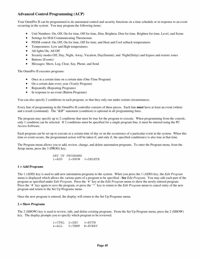
Page 45
Advanced Control Programming (ACP)
Your OmniPro II can be programmed to do automated control and security functions on a time schedule or in response to an eventoccurring in the system. You may program the following items:
• Unit Numbers: On, Off, On for time, Off for time, Dim, Brighten, Dim for time, Brighten for time, Level, and Scene• Settings for HAI Communicating Thermostats• PESM control: On, Off, On for time, Off for time, and Heat and Cool setback temperatures• Temperatures: Low and High temperatures• All lights On, All Off• Security modes Off, Day, Night, Away, Vacation, Day(Instant), and Night(Delay) and bypass and restore zones• Buttons (Events)• Messages: Show, Log, Clear, Say, Phone, and Send
The OmniPro II executes programs:
• Once at a certain time on a certain date (One-Time Program)• On a certain date every year (Yearly Program)• Repeatedly (Repeating Programs)• In response to an event (Button Programs)
You can also specify 2 conditions in each program, so that they only run under certain circumstances.
Every line of programming in the OmniPro II controller consists of three pieces. Each line must have at least an event (when)and a result (command). The "&IF" statement (condition) is optional in all programming lines.
The program may specify up to 2 conditions that must be true for the program to execute. When programming from the console,only 1 condition can be selected. If 2 conditions must be specified for a single program line, it must be entered using the PCAccess Software.
Each program can be set up to execute at a certain time of day or on the occurrence of a particular event in the system. When thistime or event occurs, the programmed action will be taken if, and only if, the specified condition(s) is also true at that time.
The Program menu allows you to add, review, change, and delete automation programs. To enter the Program menu, from theSetup menu, press the 3 (PROG) key.
SET UP PROGRAMS1=ADD 2=SHOW 3=DELETE
1 = Add Programs
The 1 (ADD) key is used to add new automation programs to the system. When you press the 1 (ADD) key, the Edit Programmenu is displayed which allows the various parts of a program to be specified - See Edit Program. You may edit each part of theprogram as specified under Edit Program. Press the ' # ' key at the Edit Program menu to show the newly entered program.Press the ' # ' key again to save the program, or press the ' * ' key to return to the Edit Program menu to cancel entry of the newprogram and return to the Set Up Programs menu.
Once the new program is entered, the display will return to the Set Up Programs menu.
2 = Show Programs
The 2 (SHOW) key is used to review, edit, and delete existing programs. From the Set Up Program menu, press the 2 (SHOW)key. The display prompts you to specify which program to be reviewed.
1=CTRL 2=SEC 3=BTTN4=ALL 5=TEMP #=EVERY
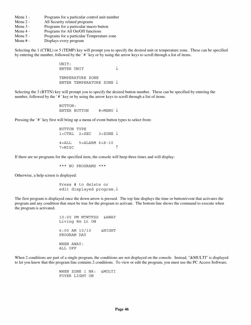
Page 46
Menu 1 - Programs for a particular control unit numberMenu 2 - All Security related programsMenu 3 - Programs for a particular macro buttonMenu 4 - Programs for All On/Off functionsMenu 5 - Programs for a particular Temperature zoneMenu # - Displays every program
Selecting the 1 (CTRL) or 5 (TEMP) key will prompt you to specify the desired unit or temperature zone. These can be specifiedby entering the number, followed by the ' # ' key or by using the arrow keys to scroll through a list of items.
UNIT:ENTER UNIT ↓
TEMPERATURE ZONEENTER TEMPERATURE ZONE ↓
Selecting the 3 (BTTN) key will prompt you to specify the desired button number. These can be specified by entering thenumber, followed by the ' # ' key or by using the arrow keys to scroll through a list of items.
BUTTON:ENTER BUTTON #=MENU ↓
Pressing the ' # ' key first will bring up a menu of event button types to select from:
BUTTON TYPE1=CTRL 2=SEC 3=ZONE ↓
4=ALL 5=ALARM 6=X-107=MISC ↑
If there are no programs for the specified item, the console will beep three times and will display:
*** NO PROGRAMS ***
Otherwise, a help screen is displayed:
Press # to delete oredit displayed program.↓
The first program is displayed once the down arrow is pressed. The top line displays the time or button/event that activates theprogram and any condition that must be true for the program to activate. The bottom line shows the command to execute whenthe program is activated.
10:00 PM MTWTFSS &AWAYLiving Rm Lt ON
6:00 AM 10/10 &NIGHTPROGRAM DAY
WHEN AWAY:ALL OFF
When 2 conditions are part of a single program, the conditions are not displayed on the console. Instead, "&MULTI" is displayedto let you know that this program line contains 2 conditions. To view or edit the program, you must use the PC Access Software.
WHEN ZONE 1 NR: &MULTIFOYER LIGHT ON
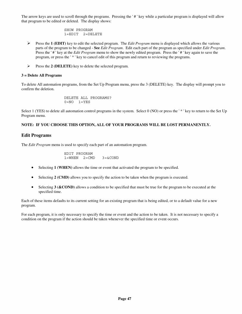
Page 47
The arrow keys are used to scroll through the programs. Pressing the ' # ' key while a particular program is displayed will allowthat program to be edited or deleted. The display shows:
SHOW PROGRAM1=EDIT 2=DELETE
Press the 1 (EDIT) key to edit the selected program. The Edit Program menu is displayed which allows the variousparts of the program to be changed - See Edit Program. Edit each part of the program as specified under Edit Program.Press the ' # ' key at the Edit Program menu to show the newly edited program. Press the ' # ' key again to save theprogram, or press the ' * ' key to cancel edit of this program and return to reviewing the programs.
Press the 2 (DELETE) key to delete the selected program.
3 = Delete All Programs
To delete All automation programs, from the Set Up Program menu, press the 3 (DELETE) key. The display will prompt you toconfirm the deletion.
DELETE ALL PROGRAMS?0=NO 1=YES
Select 1 (YES) to delete all automation control programs in the system. Select 0 (NO) or press the ' * ' key to return to the Set UpProgram menu.
NOTE: IF YOU CHOOSE THIS OPTION, ALL OF YOUR PROGRAMS WILL BE LOST PERMANENTLY.
Edit Programs
The Edit Program menu is used to specify each part of an automation program.
EDIT PROGRAM1=WHEN 2=CMD 3=&COND
• Selecting 1 (WHEN) allows the time or event that activated the program to be specified.
• Selecting 2 (CMD) allows you to specify the action to be taken when the program is executed.
• Selecting 3 (&COND) allows a condition to be specified that must be true for the program to be executed at thespecified time.
Each of these items defaults to its current setting for an existing program that is being edited, or to a default value for a newprogram.
For each program, it is only necessary to specify the time or event and the action to be taken. It is not necessary to specify acondition on the program if the action should be taken whenever the specified time or event occurs.
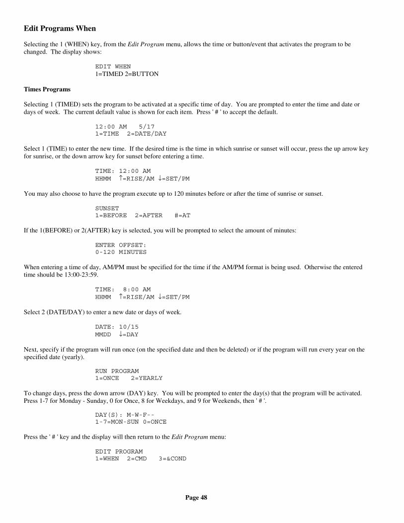
Page 48
Edit Programs When
Selecting the 1 (WHEN) key, from the Edit Program menu, allows the time or button/event that activates the program to bechanged. The display shows:
EDIT WHEN1=TIMED 2=BUTTON
Times Programs
Selecting 1 (TIMED) sets the program to be activated at a specific time of day. You are prompted to enter the time and date ordays of week. The current default value is shown for each item. Press ' # ' to accept the default.
12:00 AM 5/171=TIME 2=DATE/DAY
Select 1 (TIME) to enter the new time. If the desired time is the time in which sunrise or sunset will occur, press the up arrow keyfor sunrise, or the down arrow key for sunset before entering a time.
TIME: 12:00 AMHHMM ↑=RISE/AM ↓=SET/PM
You may also choose to have the program execute up to 120 minutes before or after the time of sunrise or sunset.
SUNSET1=BEFORE 2=AFTER #=AT
If the 1(BEFORE) or 2(AFTER) key is selected, you will be prompted to select the amount of minutes:
ENTER OFFSET:0-120 MINUTES
When entering a time of day, AM/PM must be specified for the time if the AM/PM format is being used. Otherwise the enteredtime should be 13:00-23:59.
TIME: 8:00 AMHHMM ↑=RISE/AM ↓=SET/PM
Select 2 (DATE/DAY) to enter a new date or days of week.
DATE: 10/15MMDD ↓=DAY
Next, specify if the program will run once (on the specified date and then be deleted) or if the program will run every year on thespecified date (yearly).
RUN PROGRAM1=ONCE 2=YEARLY
To change days, press the down arrow (DAY) key. You will be prompted to enter the day(s) that the program will be activated.Press 1-7 for Monday - Sunday, 0 for Once, 8 for Weekdays, and 9 for Weekends, then ' # '.
DAY(S): M-W-F--1-7=MON-SUN 0=ONCE
Press the ' # ' key and the display will then return to the Edit Program menu:
EDIT PROGRAM1=WHEN 2=CMD 3=&COND
Page 49
Button and Event Programs
Selecting 2 (BUTTON), from the "Edit When" menu, sets up a program to be activated when a macro button is executed or anevent occurs. The user is prompted to specify the button/event that activates the program:
BUTTON:ENTER BUTTON #=MENU ↓
A specific macro button may be activated by entering the button number followed by the ' # ' key, or by using the arrow keys toscroll through a list of buttons.
To program specific event buttons (i.e. Front Door Opens, Security Armed Away, Porch Light Turns On, etc.), press the ' # ' keyto bring up a menu of event button types:
BUTTON TYPE1=CTRL 2=SEC 3=ZONE ↓
4=ALL 5=ALARM 6=X-107=MISC 8=MSG ↑
After the event button is specified, the display returns to the Edit Program menu.
Control Unit Event Buttons
Pressing the 1 (CTRL) key allows you to select the event button for a control unit activated event. You are first prompted to enterthe desired unit number:
UNIT:ENTER UNIT ↓
The unit may be selected by entering the unit number followed by the ' # ' key or use the arrow keys to scroll through a list ofunits. Next, the desired unit is displayed and you are prompted to specify the state that activates the event button:
WHEN Porch Light:0=OFF 1=ON
ALC Switch Module Activated Events
When an ALC Switch Module is turned on or off, if programmed, the "When Unit" program is activated.
Pressing the 1 (CTRL) key allows you to select the "When Command" for an ALC Switch Module activated event. You are firstprompted to enter the desired unit number:
UNIT:ENTER UNIT ↓
The unit may be entered by entering the unit number followed by the ' # ' key or by using the arrow keys to scroll through a list ofunit names. Next, the desired unit is displayed and you are prompted to specify the state that activates the program:
WHEN FOYER LIGHT:0=OFF 1=ON
Security Mode Event Buttons
Pressing the 2 (SEC) key allows you to select the event button that will be activated when a security mode changes:
0=OFF 1=DAY 2=NIGHT3=AWAY 4=VACATION ↕
Page 50
After the security mode is selected, an additional menu appears which allows you to further specify the event button. Forexample, you would like to activate an event button when you arm the system into the 3 (AWAY) mode:
WHEN AWAY:1=DELAY 2=CODE 3=AREA
Any of these may be selected alone or in combination. As each item is specified, the menu is redisplayed with the updated eventbutton description. Press the ' # ' key when done.
- Selecting 1 (DLY) allows the user to specify whether the event button is activated at the start or end of the exit delay:
WHEN ACTIVATED?1=START EXIT 2=END EXIT
When you specify that the event button is activated at the start of the delay by pressing the 1 (START EXIT) key, the mode isprefixed by "A-" for "arming into".
WHEN AWAY: (END OF DELAY)WHEN A-AWY: (START OF DELAY)
When the system is armed in the Day (instant) or Night (delay) mode, event buttons for the Day and Night modes are executed,respectively.
- Selecting 2 (CODE) allows you to specify that the event button is activated only when a particular code is used. You will beprompted to enter the code:
ENTER USER CODE:1-16 0=ALL ↓
You should enter the user code by entering the code number followed by the ' # ' key or by using the arrow keys to scroll througha list of code names.
WHEN C1 AWAY:1=DELAY 2=CODE 3=AREA
- Selecting 3 (AREA) allows you to specify that the event button is activated only when the specified area is armed ordisarmed. You will be prompted to enter the area:
AREA:ENTER AREA 0=ALL ↓
The area number should be entered followed by the ' # ' key, or the arrow keys may be used to scroll through a list of areas.
WHEN C1 A1 AWAY:1=DELAY 2=CODE 3=AREA
Zone Event Buttons
Pressing the 3 (ZONE) key allows you to select the event button for a zone activation event. You are first prompted to enter thedesired zone number:
ZONE:ENTER ZONE ↓
The zone number should be entered followed by the ' # ' key, or the arrow keys may be used to scroll through a list of zones. Thedesired zone is then displayed and you are prompted to specify the state that activates the event button:
WHEN Front Door:0=SECURE 1=NOT RDY
Page 51
All On/Off Event Buttons
Pressing the 4 (ALL) key allows you to specify an event button activated by issuing an All On or an All Off command. You arefirst prompted to specify whether the event button is for All Lights On or for All Off:
ALL0=ALL OFF 1=LIGHTS ON
If area arming is being used, you will be prompted to specify the desired area:
AREA:ENTER AREA 0=ALL ↓
Alarm Event Buttons
Pressing the 5 (ALARM) key allows you to specify an event button activated upon the occurrence of an alarm. You are firstprompted to select the type of alarm:
SELECT ALARM TYPEANY TYPE ↓
The arrow keys are used to select from a list of alarm types:
• ANY ALARM
• BURGLARY ALARM
• FIRE ALARM
• GAS ALARM
• AUXILIARY ALARM
• FREEZE ALARM
• WATER ALARM
• DURESS ALARM
• TEMPERATURE ALARM
Press the ' # ' key when the desired alarm type is shown. You are then prompted to specify the area, if area arming is being used:
AREA:ENTER AREA 0=ALL ↓
T he area number should be entered followed by the ' # ' key, or the arrow keys may be used to scroll through a list of areas.
X-10 Event Buttons
Pressing the 6 (X-10) key allows you to specify an event button activation upon receipt of an X-10 command from a sourceexternal to OmniPro II. The OmniPro II can also respond to scene changes initiated at Compose keypads and dimmers. When ascene change is initiated, OmniPro II can activate an event button program. You are first prompted to enter the X-10 house code:
X-10 HOUSE CODE:1-16=A-P
You are then prompted to enter the X-10 unit code:
X-10 UNIT CODE:1-16 0=ALL
Finally, you are prompted to specify the command that activates the event button:
WHEN X-10 A1:0=OFF 1=ON 2=SCENE
Page 52
After specifying the X-10 House Code and X-10 Unit Code, select 0 for Off, 1 for On, or 2 for Scene.
"Off" events will be activated whenever the selected device is turned off. "On" events will be activated whenever the selecteddevice is turned on. "Scene" events will be activated whenever the selected device is set to the specified scene. "On" events willalso be activated whenever the selected device is set to a scene other than off.
Miscellaneous Event Buttons
Pressing the 7 (MISC) key allows you to select an event button from a list of other event buttons. You are first prompted to selectthe event button:
SELECT BUTTON:WHEN PHONE DEAD ↓
The arrow keys are used to select from a list of event buttons:
• WHEN ENERGY LO
• WHEN ENERGY MID
• WHEN ENERGY HI
• WHEN ENERGY CRIT
• WHEN PHONE DEAD
• WHEN PHONE RING
• WHEN PHONE OFFHK
• WHEN PHONE ONHOOK
• WHEN AC PWR OFF
• WHEN AC PWR ON
• WHEN BATTERY LOW
• WHEN BATTERY OK
• WHEN DCM FAIL
• WHEN DCM OK
Message Event Buttons (Pro-Link)
Pressing the 8 (MSG) key allows you to select an event button from a list of the 128 text messages. You are first prompted toselect the message:
MESSAGE:ENTER MESSAGE ↓
The message may be entered by entering the message number followed by the ' # ' key or by using the arrow keys to scrollthrough the list of messages.
Pro-Link also has the capability to monitor the serial port for incoming text messages. When a text message is received, Pro-Linksearches through all 128 text messages for a matching message. If one is found, the When Message Received event buttoncorresponding to the matching message is activated.
Pro-Link determines that a message has been received when:
• One or more characters have been received followed by 100 ms of silence• One or more characters followed by a carriage return character are received• One or more characters followed by a line feed character are received
It is not necessary to enter the terminating carriage return or line feed character as part of the message name.
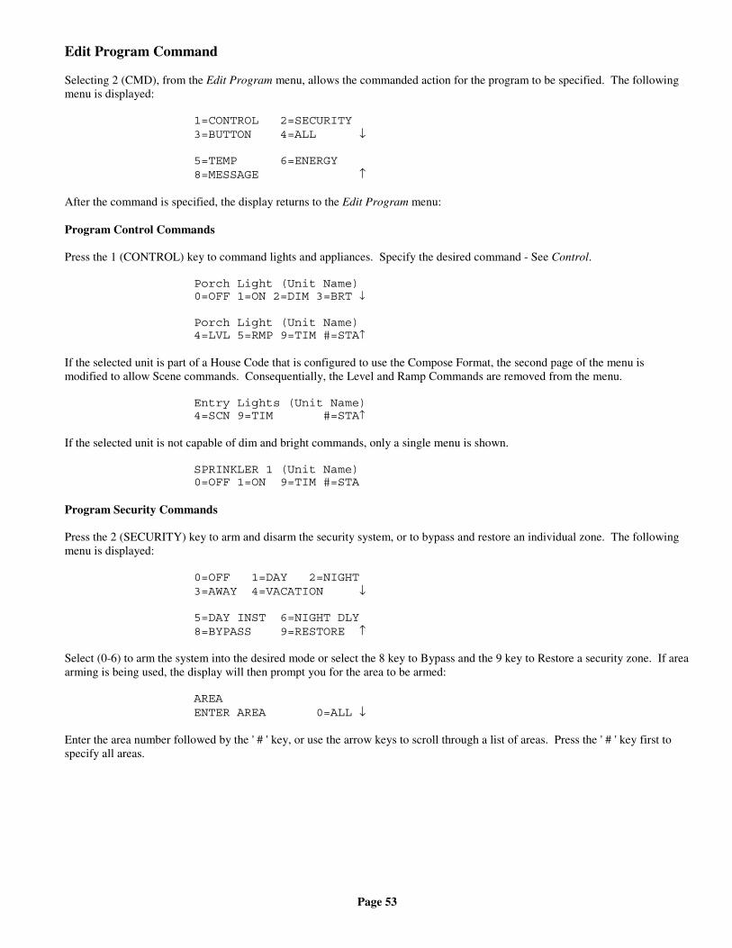
Page 53
Edit Program Command
Selecting 2 (CMD), from the Edit Program menu, allows the commanded action for the program to be specified. The followingmenu is displayed:
1=CONTROL 2=SECURITY3=BUTTON 4=ALL ↓
5=TEMP 6=ENERGY8=MESSAGE ↑
After the command is specified, the display returns to the Edit Program menu:
Program Control Commands
Press the 1 (CONTROL) key to command lights and appliances. Specify the desired command - See Control.
Porch Light (Unit Name)0=OFF 1=ON 2=DIM 3=BRT ↓
Porch Light (Unit Name)4=LVL 5=RMP 9=TIM #=STA↑
If the selected unit is part of a House Code that is configured to use the Compose Format, the second page of the menu ismodified to allow Scene commands. Consequentially, the Level and Ramp Commands are removed from the menu.
Entry Lights (Unit Name)4=SCN 9=TIM #=STA↑
If the selected unit is not capable of dim and bright commands, only a single menu is shown.
SPRINKLER 1 (Unit Name)0=OFF 1=ON 9=TIM #=STA
Program Security Commands
Press the 2 (SECURITY) key to arm and disarm the security system, or to bypass and restore an individual zone. The followingmenu is displayed:
0=OFF 1=DAY 2=NIGHT3=AWAY 4=VACATION ↓
5=DAY INST 6=NIGHT DLY8=BYPASS 9=RESTORE ↑
Select (0-6) to arm the system into the desired mode or select the 8 key to Bypass and the 9 key to Restore a security zone. If areaarming is being used, the display will then prompt you for the area to be armed:
AREAENTER AREA 0=ALL ↓
Enter the area number followed by the ' # ' key, or use the arrow keys to scroll through a list of areas. Press the ' # ' key first tospecify all areas.
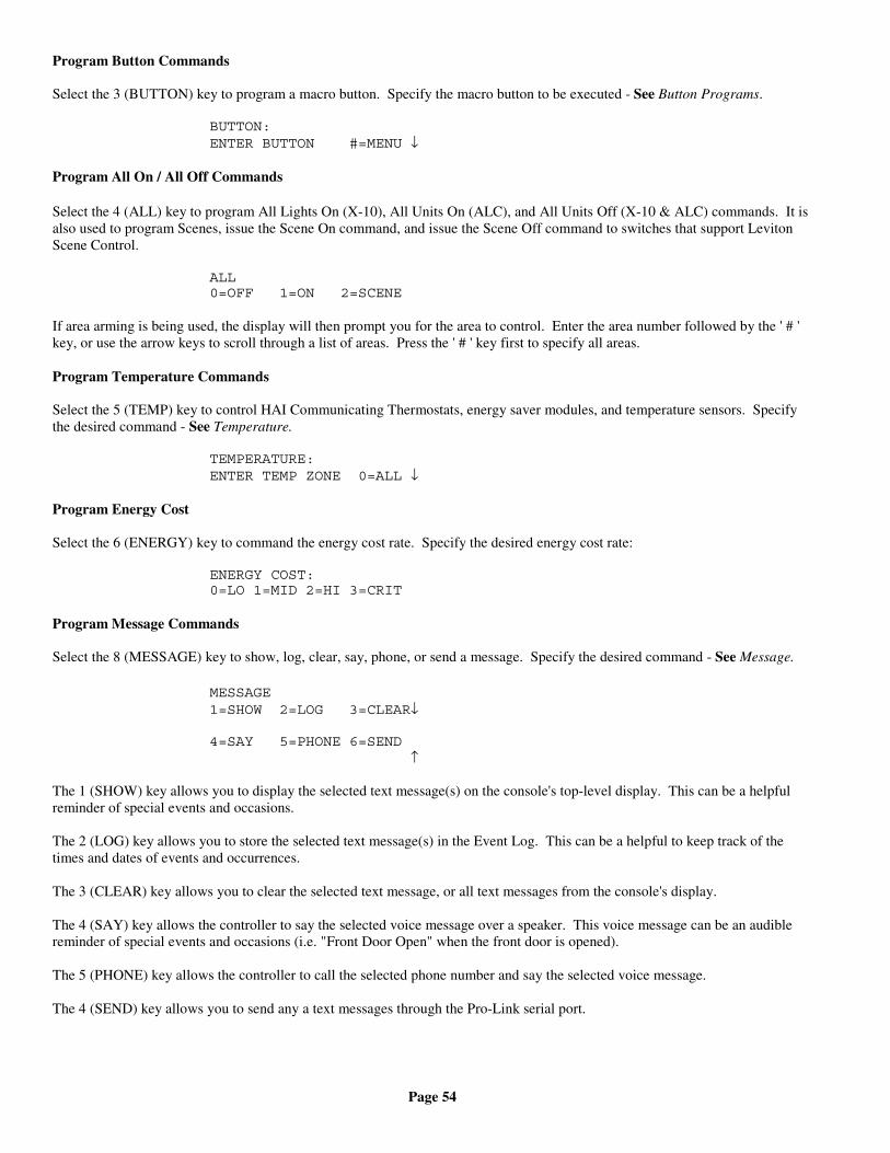
Page 54
Program Button Commands
Select the 3 (BUTTON) key to program a macro button. Specify the macro button to be executed - See Button Programs.
BUTTON:ENTER BUTTON #=MENU ↓
Program All On / All Off Commands
Select the 4 (ALL) key to program All Lights On (X-10), All Units On (ALC), and All Units Off (X-10 & ALC) commands. It isalso used to program Scenes, issue the Scene On command, and issue the Scene Off command to switches that support LevitonScene Control.
ALL0=OFF 1=ON 2=SCENE
If area arming is being used, the display will then prompt you for the area to control. Enter the area number followed by the ' # 'key, or use the arrow keys to scroll through a list of areas. Press the ' # ' key first to specify all areas.
Program Temperature Commands
Select the 5 (TEMP) key to control HAI Communicating Thermostats, energy saver modules, and temperature sensors. Specifythe desired command - See Temperature.
TEMPERATURE:ENTER TEMP ZONE 0=ALL ↓
Program Energy Cost
Select the 6 (ENERGY) key to command the energy cost rate. Specify the desired energy cost rate:
ENERGY COST:0=LO 1=MID 2=HI 3=CRIT
Program Message Commands
Select the 8 (MESSAGE) key to show, log, clear, say, phone, or send a message. Specify the desired command - See Message.
MESSAGE1=SHOW 2=LOG 3=CLEAR↓
4=SAY 5=PHONE 6=SEND ↑
The 1 (SHOW) key allows you to display the selected text message(s) on the console's top-level display. This can be a helpfulreminder of special events and occasions.
The 2 (LOG) key allows you to store the selected text message(s) in the Event Log. This can be a helpful to keep track of thetimes and dates of events and occurrences.
The 3 (CLEAR) key allows you to clear the selected text message, or all text messages from the console's display.
The 4 (SAY) key allows the controller to say the selected voice message over a speaker. This voice message can be an audiblereminder of special events and occasions (i.e. "Front Door Open" when the front door is opened).
The 5 (PHONE) key allows the controller to call the selected phone number and say the selected voice message.
The 4 (SEND) key allows you to send any a text messages through the Pro-Link serial port.
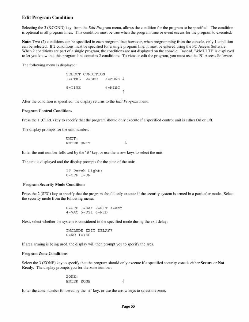
Page 55
Edit Program Condition
Selecting the 3 (&COND) key, from the Edit Program menu, allows the condition for the program to be specified. The conditionis optional in all program lines. This condition must be true when the program time or event occurs for the program to executed.
Note: Two (2) conditions can be specified in each program line; however, when programming from the console, only 1 conditioncan be selected. If 2 conditions must be specified for a single program line, it must be entered using the PC Access Software.When 2 conditions are part of a single program, the conditions are not displayed on the console. Instead, "&MULTI" is displayedto let you know that this program line contains 2 conditions. To view or edit the program, you must use the PC Access Software.
The following menu is displayed:
SELECT CONDITION1=CTRL 2=SEC 3=ZONE ↓
9=TIME #=MISC ↑
After the condition is specified, the display returns to the Edit Program menu.
Program Control Conditions
Press the 1 (CTRL) key to specify that the program should only execute if a specified control unit is either On or Off.
The display prompts for the unit number:
UNIT:ENTER UNIT ↓
Enter the unit number followed by the ' # ' key, or use the arrow keys to select the unit.
The unit is displayed and the display prompts for the state of the unit:
IF Porch Light:0=OFF 1=ON
Program Security Mode Conditions
Press the 2 (SEC) key to specify that the program should only execute if the security system is armed in a particular mode. Selectthe security mode from the following menu:
0=OFF 1=DAY 2=NIT 3=AWY4=VAC 5=DYI 6=NTD
Next, select whether the system is considered in the specified mode during the exit delay:
INCLUDE EXIT DELAY?0=NO 1=YES
If area arming is being used, the display will then prompt you to specify the area.
Program Zone Conditions
Select the 3 (ZONE) key to specify that the program should only execute if a specified security zone is either Secure or NotReady. The display prompts you for the zone number:
ZONE:ENTER ZONE ↓
Enter the zone number followed by the ' # ' key, or use the arrow keys to select the zone.
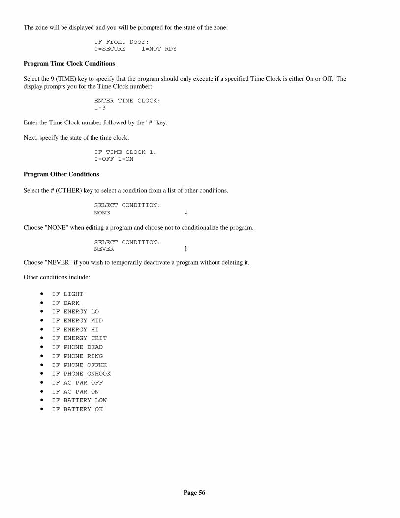
Page 56
The zone will be displayed and you will be prompted for the state of the zone:
IF Front Door:0=SECURE 1=NOT RDY
Program Time Clock Conditions
Select the 9 (TIME) key to specify that the program should only execute if a specified Time Clock is either On or Off. Thedisplay prompts you for the Time Clock number:
ENTER TIME CLOCK:1-3
Enter the Time Clock number followed by the ' # ' key.
Next, specify the state of the time clock:
IF TIME CLOCK 1:0=OFF 1=ON
Program Other Conditions
Select the # (OTHER) key to select a condition from a list of other conditions.
SELECT CONDITION:NONE ↓
Choose "NONE" when editing a program and choose not to conditionalize the program.
SELECT CONDITION:NEVER ↕
Choose "NEVER" if you wish to temporarily deactivate a program without deleting it.
Other conditions include:
• IF LIGHT
• IF DARK
• IF ENERGY LO
• IF ENERGY MID
• IF ENERGY HI
• IF ENERGY CRIT
• IF PHONE DEAD
• IF PHONE RING
• IF PHONE OFFHK
• IF PHONE ONHOOK
• IF AC PWR OFF
• IF AC PWR ON
• IF BATTERY LOW
• IF BATTERY OK
Page 57
Set Up Dial
The Set Up Dial menu is used to configure all of the telephone related items for the OmniPro II. To enter the Set Up Dial menu,from the Setup menu, press the 4 (DIAL) key. Use the arrows to scroll through the items. For each item, the top line displays adescription of the item and its current setting. The bottom line shows the available ranges for your selections.
Phone numbers can be up to 24 characters long. The number is shown on the bottom line of the display. Press the OFF key toenter a ' - ' into the number. Press the DAY key to specify a pause of 2 seconds (shown as a "T" on the display). Press theNIGHT key to enter a ' # ' into the number. Enter a single ' - ' for no number.
Telephone Access
The Telephone Access item allows you to turn the local (in-house) and remote telephone control feature on and off.
If set to On, the OmniPro II will allow local and remote telephone access as described in Telephone Control. If set to Off, theOmniPro II will not answer incoming calls ever, and will not work on the in house phones. Dial outs will still occur, and thesystem will operate normally when the OmniPro II dials out.
If you do not have your OmniPro II connected to a phone line, set Telephone Access to Off to keep the system from displaying"PHONE LINE DEAD". The default setting for Telephone Access is On.
Answer Outside Call
If you do not want your system to Answer Outside Call, set this item to No. The local (in-house) telephone control features willstill work, but the system will never answer an incoming call.
The default setting for Answer Outside Call is Yes.
Remote Commands
The Remote Commands Ok item allows you to prevent any commands from being issued from a remote telephone.
If Remote Commands Ok is set to Yes, the OmniPro II will allow all commands to be executed when called from a remotetelephone. If Remote Commands Ok is set to No, then lights, appliances, and the security system cannot be controlled from aremote telephone that dials into your home.
You can issue commands from a local (in-house) phone with Remote Commands Ok set to Yes or No. The default setting is Yes.
Rings Before Answer
Your phone must ring this number of times before the OmniPro II will answer an incoming call to your phone.
To change Rings Before Answer, enter the new number from 1 to 15, then press the ' # ' key. The factory default setting is 8.
Dial Type
The Dial Type specifies the type of dialing used when the OmniPro II dials out. If you do not have Touch-Tone service, then DialType must be set to Pulse.
The default Dial Type is Tone.
My Phone Number
My Phone Number is the phone number that will be announced when the OmniPro II dials out in the event of an alarm. It shouldbe set to the phone number of the premises where your system is installed.
To enter phone numbers, press the keypad keys 0 - 9. You can put in a dash (-) for legibility by pressing the Off key.
Press the ' # ' key after you have pressed all of the digits in the phone number. For example, to enter the number 555-1234, press555 "OFF" 1234 #.
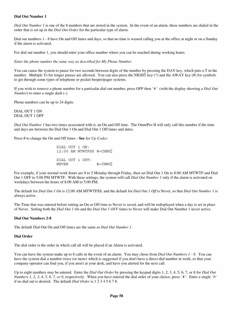
Page 58
Dial Out Number 1
Dial Out Number 1 is one of the 8 numbers that are stored in the system. In the event of an alarm, these numbers are dialed in theorder that is set up in the Dial Out Order for the particular type of alarm.
Dial out numbers 1 - 8 have On and Off times and days, so that no time is wasted calling you at the office at night or on a Sundayif the alarm is activated.
For dial out number 1, you should enter your office number where you can be reached during working hours.
Enter the phone number the same way as described for My Phone Number.
You can cause the system to pause for two seconds between digits of the number by pressing the DAY key, which puts a T in thenumber. Multiple Ts for longer pauses are allowed. You can also press the NIGHT key (*) and the AWAY key (#) for symbolsto get through some types of telephone or pocket beeper/pager systems.
If you wish to remove a phone number for a particular dial out number, press OFF then ' # ' (with the display showing a Dial OutNumber) to enter a single dash (-).
Phone numbers can be up to 24 digits.
DIAL OUT 1 ONDIAL OUT 1 OFF
Dial Out Number 1 has two times associated with it, an On and Off time. The OmniPro II will only call this number if the timeand days are between the Dial Out 1 On and Dial Out 1 Off times and dates.
Press # to change the On and Off times - See Set Up Codes.
DIAL OUT 1 ON:12:00 AM MTWTFSS #=CHNG↕
DIAL OUT 1 OFF:NEVER #=CHNG↕
For example, if your normal work hours are 8 to 5 Monday through Friday, then set Dial Out 1 On to 8:00 AM MTWTF and DialOut 1 OFF to 5:00 PM MTWTF. With these settings, the system will call Dial Out Number 1 only if the alarm is activated onweekdays between the hours of 8:00 AM to 5:00 PM.
The default for Dial Out 1 On is 12:00 AM MTWTFSS, and the default for Dial Out 1 Off is Never, so that Dial Out Number 1 isalways active.
The Time that was entered before setting an On or Off time to Never is saved, and will be redisplayed when a day is set in placeof Never. Setting both the Dial Out 1 On and the Dial Out 1 OFF times to Never will make Dial Out Number 1 never active.
Dial Out Numbers 2-8
The default Dial Out On and Off times are the same as Dial Out Number 1.
Dial Order
The dial order is the order in which call all will be placed if an Alarm is activated.
You can have the system make up to 8 calls in the event of an alarm. You may chose from Dial Out Numbers 1 - 8. You canhave the system dial a number twice (or more) which is suggested if you don't have a direct dial number at work, so that yourcompany operator can find you, if you aren't at your desk, and have you alerted for the next call.
Up to eight numbers may be entered. Enter the Dial Out Order by pressing the keypad digits 1, 2, 3, 4, 5, 6, 7, or 8 for Dial OutNumbers 1, 2, 3, 4, 5, 6, 7, or 8, respectively. When you have entered the dial order of your choice, press ' # '. Enter a single ' 0 'if no dial out is desired. The default Dial Order is 1 2 3 4 5 6 7 8.
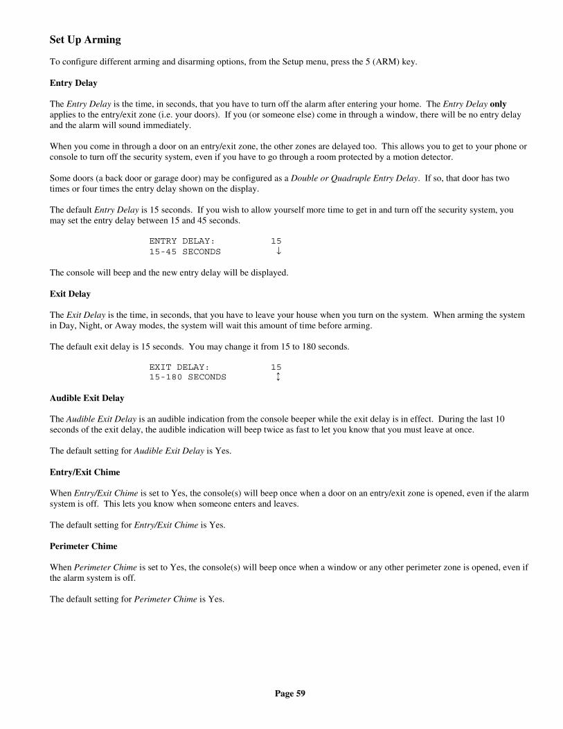
Page 59
Set Up Arming
To configure different arming and disarming options, from the Setup menu, press the 5 (ARM) key.
Entry Delay
The Entry Delay is the time, in seconds, that you have to turn off the alarm after entering your home. The Entry Delay onlyapplies to the entry/exit zone (i.e. your doors). If you (or someone else) come in through a window, there will be no entry delayand the alarm will sound immediately.
When you come in through a door on an entry/exit zone, the other zones are delayed too. This allows you to get to your phone orconsole to turn off the security system, even if you have to go through a room protected by a motion detector.
Some doors (a back door or garage door) may be configured as a Double or Quadruple Entry Delay. If so, that door has twotimes or four times the entry delay shown on the display.
The default Entry Delay is 15 seconds. If you wish to allow yourself more time to get in and turn off the security system, youmay set the entry delay between 15 and 45 seconds.
ENTRY DELAY: 1515-45 SECONDS ↓
The console will beep and the new entry delay will be displayed.
Exit Delay
The Exit Delay is the time, in seconds, that you have to leave your house when you turn on the system. When arming the systemin Day, Night, or Away modes, the system will wait this amount of time before arming.
The default exit delay is 15 seconds. You may change it from 15 to 180 seconds.
EXIT DELAY: 1515-180 SECONDS ↕
Audible Exit Delay
The Audible Exit Delay is an audible indication from the console beeper while the exit delay is in effect. During the last 10seconds of the exit delay, the audible indication will beep twice as fast to let you know that you must leave at once.
The default setting for Audible Exit Delay is Yes.
Entry/Exit Chime
When Entry/Exit Chime is set to Yes, the console(s) will beep once when a door on an entry/exit zone is opened, even if the alarmsystem is off. This lets you know when someone enters and leaves.
The default setting for Entry/Exit Chime is Yes.
Perimeter Chime
When Perimeter Chime is set to Yes, the console(s) will beep once when a window or any other perimeter zone is opened, even ifthe alarm system is off.
The default setting for Perimeter Chime is Yes.
Page 60
Enable Quick Arm
The Quick Arm feature allows the security system to be armed by pressing the desired mode key twice instead of having to enteryour code.
The default setting for Enable Quick Arm is No.
Enable Auto Bypass
The Auto-Bypass feature allows the system to automatically bypass an open zone when the system is armed, rather than setting offthe alarm. In some applications, it may be preferable to allow arming only if all zones are secure (READY).
With Auto-Bypass Off, all zones to be armed must be secure when the system is armed. Otherwise, the console will beep threetimes and display "ZONE NOT RDY". If the system is armed and a zone is open when the Exit Delay expires, the alarm willsound.
All On For Alarm
This option will instruct OmniPro II to execute an X-10 All On command in the event that any type of alarm occurs.
Beep On Trouble
If the OmniPro II detects any troubles with itself or one of the zones connected to it, it will display a message on the screen andbeep the console twice per second, continuously (i.e. beep beep...beep beep...). You can silence this sound by pressing the ' * 'key. However, if the trouble occurs again, the beeper will start beeping again.
If you do not wish to hear the beeping sound when a trouble occurs, set Beep On Trouble to No.
The default setting for Beep On Trouble is Yes.
Set up Miscellaneous
To configure Miscellaneous items in the system, from the Set Up menu, press the 6 (MISC) key.
High Security Mode
In High Security Mode, the Master or Manager code is always required to do the following functions:
• Any Control functions• Any Temperature Control• View the Event Log• Access the system from a local phone
With High Security Mode Off, no code is required to access a local telephone.
If your system is set up with High Security Mode On, the display will request the Master or Manager code whenever you selectone of these functions, even if the security system is Off. Simply enter your Master or Manager code.
Your system was shipped from the factory with High Security Mode Off, which allows you to view the event log and access thelocal phones without having to enter a code. In most residential applications, this is appropriate. If you have a commercialinstallation, or would like added protection from unauthorized access to the system, you may wish to turn on High Security Mode.
Announce Alarms
If a Two-Way Audio Module is being used in a system, this item enables the system to speak the type of alarm and zone over aspeaker on premises. When an alarm first occurs, the siren is activated. After a few seconds, the siren is turned off and the typeof alarm is announced. The siren is then reactivated.
The default for Announce Alarms is No.
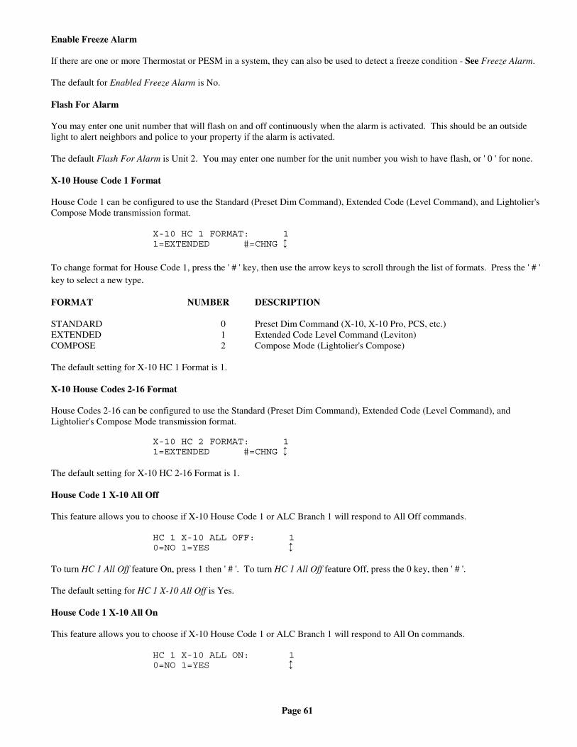
Page 61
Enable Freeze Alarm
If there are one or more Thermostat or PESM in a system, they can also be used to detect a freeze condition - See Freeze Alarm.
The default for Enabled Freeze Alarm is No.
Flash For Alarm
You may enter one unit number that will flash on and off continuously when the alarm is activated. This should be an outsidelight to alert neighbors and police to your property if the alarm is activated.
The default Flash For Alarm is Unit 2. You may enter one number for the unit number you wish to have flash, or ' 0 ' for none.
X-10 House Code 1 Format
House Code 1 can be configured to use the Standard (Preset Dim Command), Extended Code (Level Command), and Lightolier'sCompose Mode transmission format.
X-10 HC 1 FORMAT: 11=EXTENDED #=CHNG ↕
To change format for House Code 1, press the ' # ' key, then use the arrow keys to scroll through the list of formats. Press the ' # 'key to select a new type.
FORMAT NUMBER DESCRIPTION
STANDARD 0 Preset Dim Command (X-10, X-10 Pro, PCS, etc.)EXTENDED 1 Extended Code Level Command (Leviton)COMPOSE 2 Compose Mode (Lightolier's Compose)
The default setting for X-10 HC 1 Format is 1.
X-10 House Codes 2-16 Format
House Codes 2-16 can be configured to use the Standard (Preset Dim Command), Extended Code (Level Command), andLightolier's Compose Mode transmission format.
X-10 HC 2 FORMAT: 11=EXTENDED #=CHNG ↕
The default setting for X-10 HC 2-16 Format is 1.
House Code 1 X-10 All Off
This feature allows you to choose if X-10 House Code 1 or ALC Branch 1 will respond to All Off commands.
HC 1 X-10 ALL OFF: 10=NO 1=YES ↕
To turn HC 1 All Off feature On, press 1 then ' # '. To turn HC 1 All Off feature Off, press the 0 key, then ' # '.
The default setting for HC 1 X-10 All Off is Yes.
House Code 1 X-10 All On
This feature allows you to choose if X-10 House Code 1 or ALC Branch 1 will respond to All On commands.
HC 1 X-10 ALL ON: 10=NO 1=YES ↕
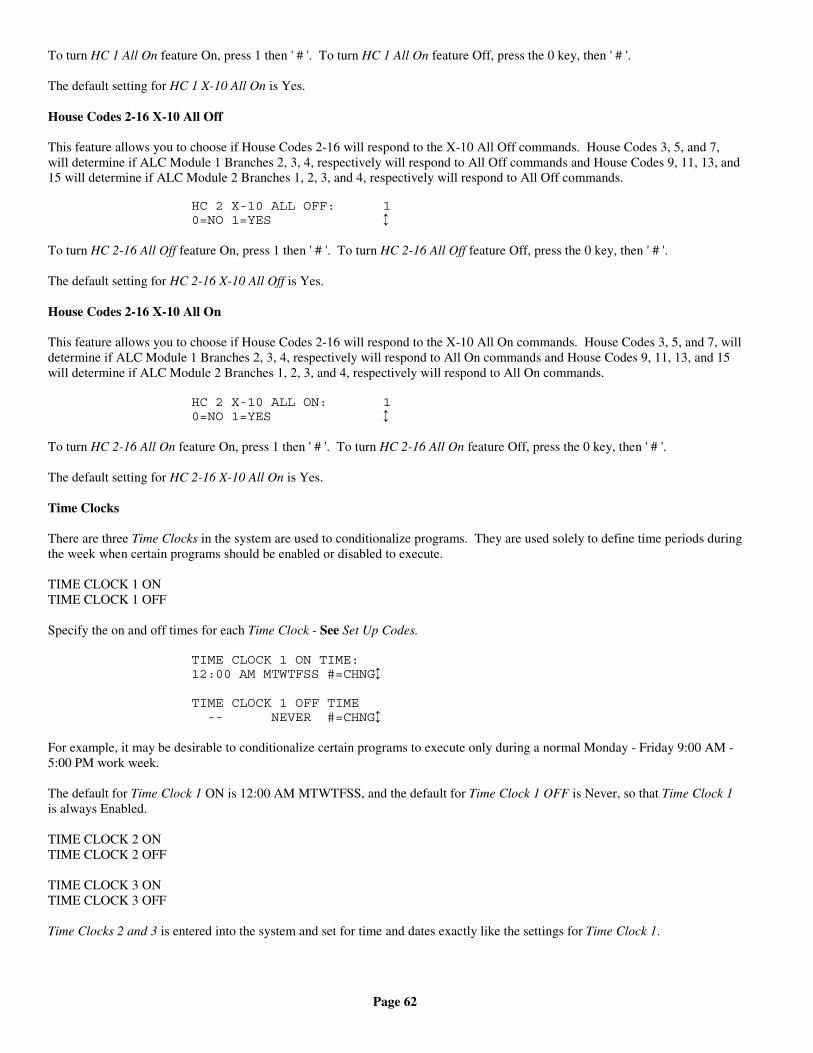
Page 62
To turn HC 1 All On feature On, press 1 then ' # '. To turn HC 1 All On feature Off, press the 0 key, then ' # '.
The default setting for HC 1 X-10 All On is Yes.
House Codes 2-16 X-10 All Off
This feature allows you to choose if House Codes 2-16 will respond to the X-10 All Off commands. House Codes 3, 5, and 7,will determine if ALC Module 1 Branches 2, 3, 4, respectively will respond to All Off commands and House Codes 9, 11, 13, and15 will determine if ALC Module 2 Branches 1, 2, 3, and 4, respectively will respond to All Off commands.
HC 2 X-10 ALL OFF: 10=NO 1=YES ↕
To turn HC 2-16 All Off feature On, press 1 then ' # '. To turn HC 2-16 All Off feature Off, press the 0 key, then ' # '.
The default setting for HC 2-16 X-10 All Off is Yes.
House Codes 2-16 X-10 All On
This feature allows you to choose if House Codes 2-16 will respond to the X-10 All On commands. House Codes 3, 5, and 7, willdetermine if ALC Module 1 Branches 2, 3, 4, respectively will respond to All On commands and House Codes 9, 11, 13, and 15will determine if ALC Module 2 Branches 1, 2, 3, and 4, respectively will respond to All On commands.
HC 2 X-10 ALL ON: 10=NO 1=YES ↕
To turn HC 2-16 All On feature On, press 1 then ' # '. To turn HC 2-16 All On feature Off, press the 0 key, then ' # '.
The default setting for HC 2-16 X-10 All On is Yes.
Time Clocks
There are three Time Clocks in the system are used to conditionalize programs. They are used solely to define time periods duringthe week when certain programs should be enabled or disabled to execute.
TIME CLOCK 1 ONTIME CLOCK 1 OFF
Specify the on and off times for each Time Clock - See Set Up Codes.
TIME CLOCK 1 ON TIME:12:00 AM MTWTFSS #=CHNG↕
TIME CLOCK 1 OFF TIME -- NEVER #=CHNG↕
For example, it may be desirable to conditionalize certain programs to execute only during a normal Monday - Friday 9:00 AM -5:00 PM work week.
The default for Time Clock 1 ON is 12:00 AM MTWTFSS, and the default for Time Clock 1 OFF is Never, so that Time Clock 1is always Enabled.
TIME CLOCK 2 ONTIME CLOCK 2 OFF
TIME CLOCK 3 ONTIME CLOCK 3 OFF
Time Clocks 2 and 3 is entered into the system and set for time and dates exactly like the settings for Time Clock 1.
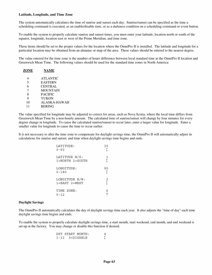
Page 63
Latitude, Longitude, and Time Zone
The system automatically calculates the time of sunrise and sunset each day. Sunrise/sunset can be specified as the time ascheduling command is executed, as an enable/disable time, or as a darkness condition on a scheduling command or event button.
To enable the system to properly calculate sunrise and sunset times, you must enter your latitude, location north or south of theequator, longitude, location east or west of the Prime Meridian, and time zone.
These items should be set to the proper values for the location where the OmniPro II is installed. The latitude and longitude for aparticular location may be obtained from an almanac or map of the area. These values should be entered to the nearest degree.
The value entered for the time zone is the number of hours difference between local standard time at the OmniPro II location andGreenwich Mean Time. The following values should be used for the standard time zones in North America:
ZONE NAME
4 ATLANTIC5 EASTERN6 CENTRAL7 MOUNTAIN8 PACIFIC9 YUKON
10 ALASKA-HAWAII11 BERING
The value specified for longitude may be adjusted to correct for areas, such as Nova Scotia, where the local time differs fromGreenwich Mean Time by a non-hourly amount. The calculated time of sunrise/sunset will change by four minutes for everydegree change in longitude. To cause the calculated sunrise/sunset to occur later, enter a larger value for longitude. Enter asmaller value for longitude to cause the time to occur earlier.
It is not necessary to alter the time zone to compensate for daylight savings time, the OmniPro II will automatically adjust itscalculations for sunrise and sunset, and time when daylight savings time begins and ends.
LATITUDE: 300-60 ↕
LATITUDE N/S: 11=NORTH 2=SOUTH ↕
LONGITUDE: 900-180 ↕
LONGITUDE E/W: 21=EAST 2=WEST ↕
TIME ZONE: 60-12 ↑
Daylight Savings
The OmniPro II automatically calculates the day of daylight savings time each year. It also adjusts the "time of day" each timedaylight savings time begins and ends.
To enable the system to properly calculate daylight savings time, a start month, start weekend, end month, and end weekend isset-up at the factory. You may change or disable this function if desired.
DST START MONTH: 41-12 0=DISABLE ↕
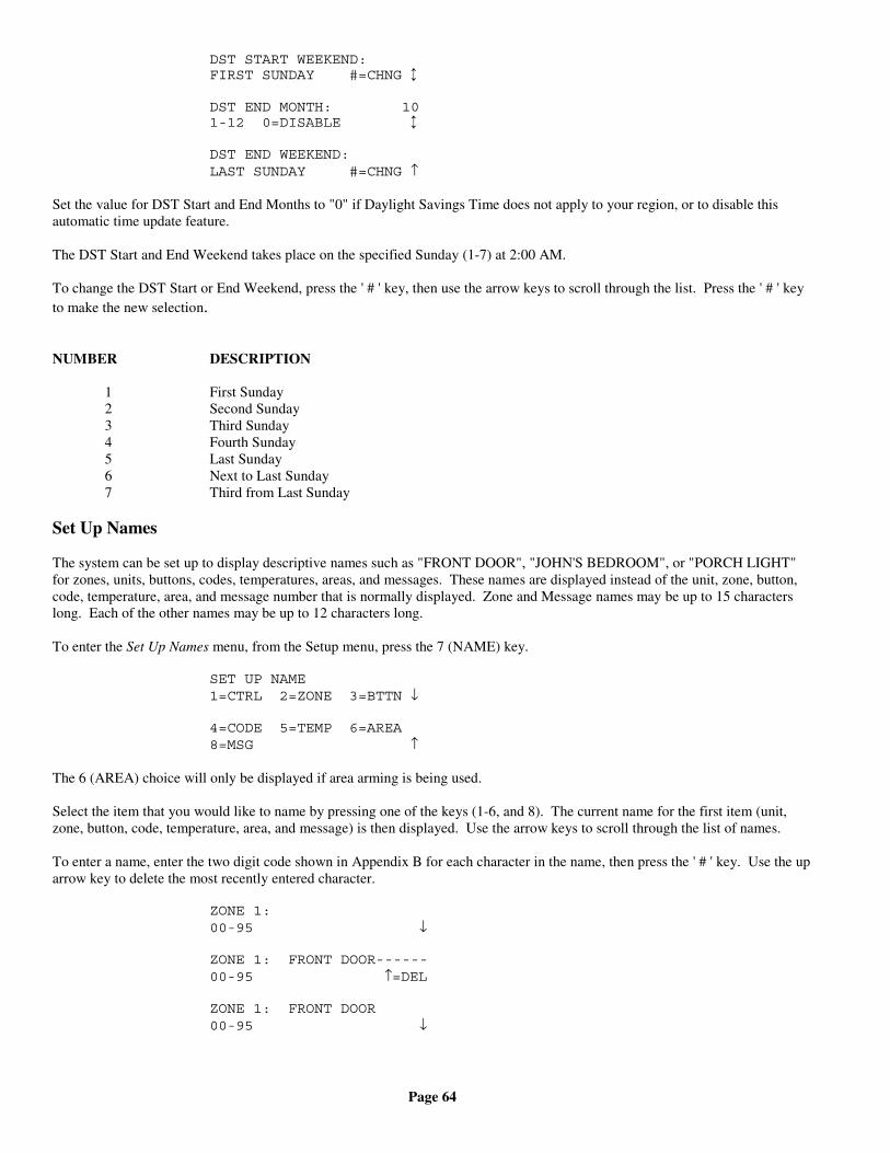
Page 64
DST START WEEKEND:FIRST SUNDAY #=CHNG ↕
DST END MONTH: 101-12 0=DISABLE ↕
DST END WEEKEND:LAST SUNDAY #=CHNG ↑
Set the value for DST Start and End Months to "0" if Daylight Savings Time does not apply to your region, or to disable thisautomatic time update feature.
The DST Start and End Weekend takes place on the specified Sunday (1-7) at 2:00 AM.
To change the DST Start or End Weekend, press the ' # ' key, then use the arrow keys to scroll through the list. Press the ' # ' keyto make the new selection.
NUMBER DESCRIPTION
1 First Sunday2 Second Sunday3 Third Sunday4 Fourth Sunday5 Last Sunday6 Next to Last Sunday7 Third from Last Sunday
Set Up Names
The system can be set up to display descriptive names such as "FRONT DOOR", "JOHN'S BEDROOM", or "PORCH LIGHT"for zones, units, buttons, codes, temperatures, areas, and messages. These names are displayed instead of the unit, zone, button,code, temperature, area, and message number that is normally displayed. Zone and Message names may be up to 15 characterslong. Each of the other names may be up to 12 characters long.
To enter the Set Up Names menu, from the Setup menu, press the 7 (NAME) key.
SET UP NAME1=CTRL 2=ZONE 3=BTTN ↓
4=CODE 5=TEMP 6=AREA8=MSG ↑
The 6 (AREA) choice will only be displayed if area arming is being used.
Select the item that you would like to name by pressing one of the keys (1-6, and 8). The current name for the first item (unit,zone, button, code, temperature, area, and message) is then displayed. Use the arrow keys to scroll through the list of names.
To enter a name, enter the two digit code shown in Appendix B for each character in the name, then press the ' # ' key. Use the uparrow key to delete the most recently entered character.
ZONE 1:00-95 ↓
ZONE 1: FRONT DOOR------00-95 ↑=DEL
ZONE 1: FRONT DOOR00-95 ↓
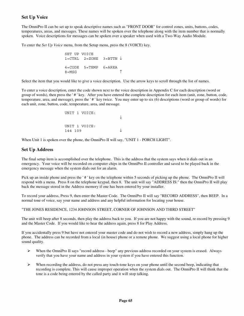
Page 65
Set Up Voice
The OmniPro II can be set up to speak descriptive names such as "FRONT DOOR" for control zones, units, buttons, codes,temperatures, areas, and messages. These names will be spoken over the telephone along with the item number that is normallyspoken. Voice descriptions for messages can be spoken over a speaker when used with a Two-Way Audio Module.
To enter the Set Up Voice menu, from the Setup menu, press the 8 (VOICE) key.
SET UP VOICE1=CTRL 2=ZONE 3=BTTN ↓
4=CODE 5=TEMP 6=AREA8=MSG ↑
Select the item that you would like to give a voice description. Use the arrow keys to scroll through the list of names.
To enter a voice description, enter the code shown next to the voice description in Appendix C for each description (word orgroup of words), then press the ' # ' key. After you have entered the complete description for each item (unit, zone, button, code,temperature, area, and message), press the ' # ' key twice. You may enter up to six (6) descriptions (word or group of words) foreach unit, zone, button, code, temperature, area, and message.
UNIT 1 VOICE: ↓
UNIT 1 VOICE:144 109 ↓
When Unit 1 is spoken over the phone, the OmniPro II will say, "UNIT 1 - PORCH LIGHT".
Set Up Address
The final setup item is accomplished over the telephone. This is the address that the system says when it dials out in anemergency. Your voice will be recorded on computer chips in the OmniPro II controller and saved to be played back in theemergency message when the system dials out for an alarm.
Pick up an inside phone and press the ' # ' key on the telephone within 5 seconds of picking up the phone. The OmniPro II willrespond with a menu. Press 8 on the telephone keypad, then 8. The unit will say "ADDRESS IS:" then the OmniPro II will playback the message stored in the Address memory if one has been entered by your installer.
To record your address, Press 9, then enter the Master Code. The OmniPro II will say "RECORD ADDRESS", then BEEP. In anormal tone of voice, say your name and address and any helpful information for locating your house.
"THE JONES RESIDENCE, 1234 JOHNSON STREET, CORNER OF JOHNSON AND THIRD STREET"
The unit will beep after 8 seconds, then play the address back to you. If you are not happy with the sound, re-record by pressing 9and the Master Code. If you would like to hear the address again, press 8 for Play Address.
If you accidentally press 9 but have not entered your master code and do not wish to record a new address, simply hang up thephone. The address can be recorded from a local (in house) phone or a remote phone. We suggest using a local phone for highersound quality.
When the OmniPro II says "record address - beep" any previous address recorded on your system is erased. Alwaysverify that you have your name and address in your system if you have entered this function.
When recording the address, do not press any touch-tone keys on your phone until the second beep, indicating thatrecording is complete. This will cause improper operation when the system dials out. The OmniPro II will think that thetone is a code being entered by the called party and it will stop talking.
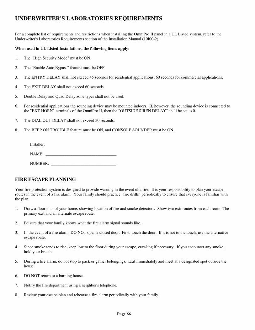
Page 66
UNDERWRITER'S LABORATORIES REQUIREMENTS
For a complete list of requirements and restrictions when installing the OmniPro II panel in a UL Listed system, refer to theUnderwriter's Laboratories Requirements section of the Installation Manual (10I00-2).
When used in UL Listed Installations, the following items apply:
1. The "High Security Mode" must be ON.
2. The "Enable Auto Bypass" feature must be OFF.
3. The ENTRY DELAY shall not exceed 45 seconds for residential applications; 60 seconds for commercial applications.
4. The EXIT DELAY shall not exceed 60 seconds.
5. Double Delay and Quad Delay zone types shall not be used.
6. For residential applications the sounding device may be mounted indoors. If, however, the sounding device is connected tothe "EXT HORN" terminals of the OmniPro II, then the "OUTSIDE SIREN DELAY" shall be set to 0.
7. The DIAL OUT DELAY shall not exceed 30 seconds.
8. The BEEP ON TROUBLE feature must be ON, and CONSOLE SOUNDER must be ON.
Installer:
NAME: __________________________________
NUMBER: _______________________________
FIRE ESCAPE PLANNING
Your fire protection system is designed to provide warning in the event of a fire. It is your responsibility to plan your escaperoutes in the event of a fire alarm. Your family should practice "fire drills" periodically to ensure that everyone is familiar withthe plan.
1. Draw a floor plan of your home, showing location of fire and smoke detectors. Show two exit routes from each room: Theprimary exit and an alternate escape route.
2. Be sure that your family knows what the fire alarm signal sounds like.
3. In the event of a fire alarm, DO NOT open a closed door. First, touch the door. If it is hot to the touch, use the alternativeescape route.
4. Since smoke tends to rise, keep low to the floor during your escape, crawling if necessary. If you encounter any smoke,hold your breath.
5. During a fire alarm, do not stop to pack or gather belongings. Exit immediately and meet at a designated spot outside thehouse.
6. DO NOT return to a burning house.
7. Notify the fire department using a neighbor's telephone.
8. Review your escape plan and rehearse a fire alarm periodically with your family.
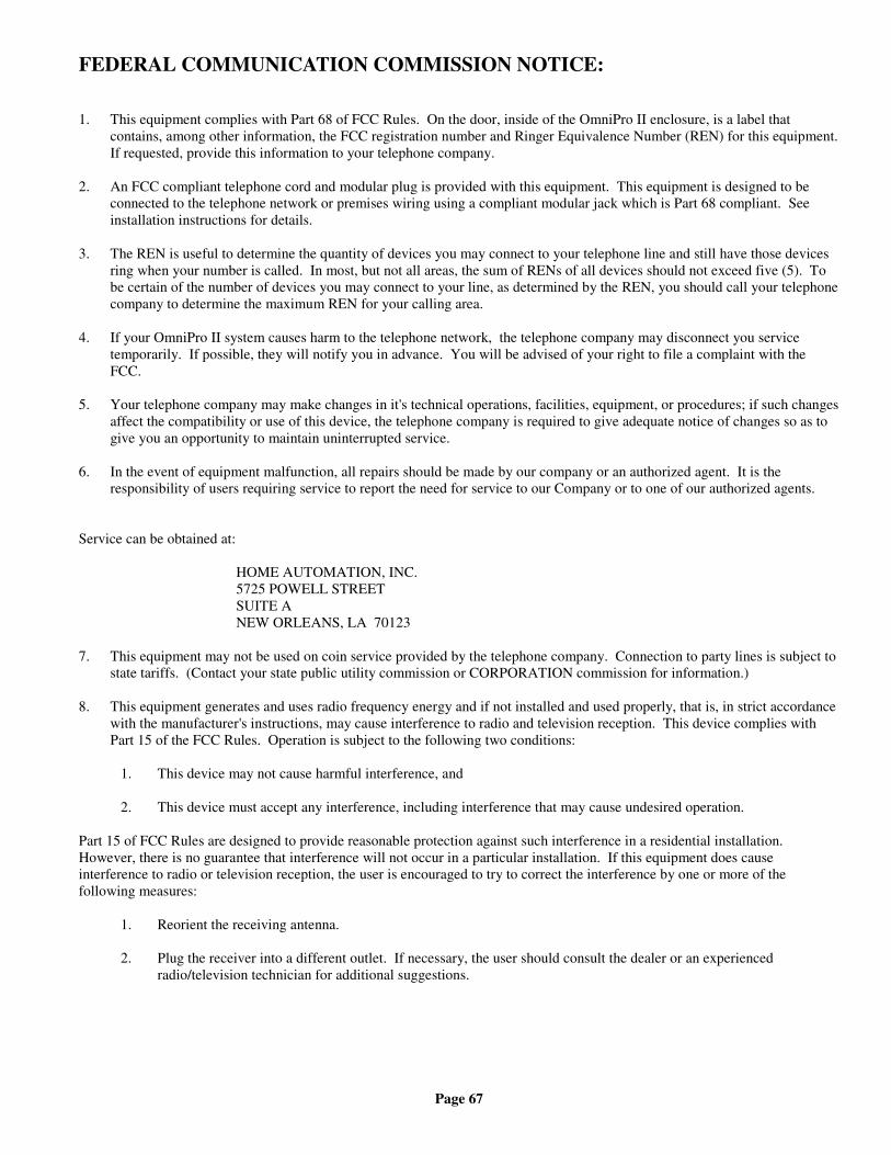
Page 67
FEDERAL COMMUNICATION COMMISSION NOTICE:
1. This equipment complies with Part 68 of FCC Rules. On the door, inside of the OmniPro II enclosure, is a label thatcontains, among other information, the FCC registration number and Ringer Equivalence Number (REN) for this equipment.If requested, provide this information to your telephone company.
2. An FCC compliant telephone cord and modular plug is provided with this equipment. This equipment is designed to beconnected to the telephone network or premises wiring using a compliant modular jack which is Part 68 compliant. Seeinstallation instructions for details.
3. The REN is useful to determine the quantity of devices you may connect to your telephone line and still have those devicesring when your number is called. In most, but not all areas, the sum of RENs of all devices should not exceed five (5). Tobe certain of the number of devices you may connect to your line, as determined by the REN, you should call your telephonecompany to determine the maximum REN for your calling area.
4. If your OmniPro II system causes harm to the telephone network, the telephone company may disconnect you servicetemporarily. If possible, they will notify you in advance. You will be advised of your right to file a complaint with theFCC.
5. Your telephone company may make changes in it's technical operations, facilities, equipment, or procedures; if such changesaffect the compatibility or use of this device, the telephone company is required to give adequate notice of changes so as togive you an opportunity to maintain uninterrupted service.
6. In the event of equipment malfunction, all repairs should be made by our company or an authorized agent. It is theresponsibility of users requiring service to report the need for service to our Company or to one of our authorized agents.
Service can be obtained at:
HOME AUTOMATION, INC.5725 POWELL STREETSUITE ANEW ORLEANS, LA 70123
7. This equipment may not be used on coin service provided by the telephone company. Connection to party lines is subject tostate tariffs. (Contact your state public utility commission or CORPORATION commission for information.)
8. This equipment generates and uses radio frequency energy and if not installed and used properly, that is, in strict accordancewith the manufacturer's instructions, may cause interference to radio and television reception. This device complies withPart 15 of the FCC Rules. Operation is subject to the following two conditions:
1. This device may not cause harmful interference, and
2. This device must accept any interference, including interference that may cause undesired operation.
Part 15 of FCC Rules are designed to provide reasonable protection against such interference in a residential installation.However, there is no guarantee that interference will not occur in a particular installation. If this equipment does causeinterference to radio or television reception, the user is encouraged to try to correct the interference by one or more of thefollowing measures:
1. Reorient the receiving antenna.
2. Plug the receiver into a different outlet. If necessary, the user should consult the dealer or an experiencedradio/television technician for additional suggestions.

Page 68
CANADIAN INDUSTRY CANADA NOTICE
Notice: The Industry Canada label identifies certified equipment. This certification means that the equipment meetscertain telecommunications network protective, operational and safety requirements. The Industry Canada does notguarantee the equipment will operate to the user's satisfaction.
Before installing this equipment, users should ensure that it is permissible to be connected to the facilities of the localtelecommunications company. The equipment must also be installed using an acceptable method of connection. In somecases, the company's inside wiring associated with a single line individual service may be extended by means of a certifiedconnector assembly (telephone extension cord). The customer should be aware that compliance with the above conditionsmay not prevent degradation of service in some situations.
Repairs to certified equipment should be made by an authorized Canadian maintenance facility designated by the supplier. Anyrepairs or alterations made by the user to this equipment, or equipment malfunctions, may give the telecommunicationscompany cause to request the user to disconnect the equipment.
Users should ensure for their own protection that the electrical ground connections of the power utility, telephone linesand internal metallic water pipe system, if present, are connected together. This precaution may be particularlyimportant in rural areas.
Caution: Users should not attempt to make such connections themselves, but should contact the appropriate electric inspectionauthority, or electrician, as appropriate.
Notice: The Ringer Equivalence Number (REN) assigned to each terminal device provides an indication of the maximumnumber of terminals allowed to be connected to a telephone interface. The termination on an interface may consist of anycombination of devices subject only to the requirement that the sum of the Ringer Equivalence Numbers of all the devices doesnot exceed 5.
This digital apparatus does not exceed the Class B limits for radio noise emissions from digital apparatus set out in the RadioInterference Regulations of the Canadian Department of Communications.
Le present appareil numerique n'emet pas de bruits radioelectriques depassant les limites applicables aux appareils numeriques dela class B prescrites dans le Reglement sur le brouillage radioelectrique edicte par le ministere des Communications du Canada.
IF YOU HAVE TROUBLE WITH YOUR PHONES
...and you suspect that your OmniPro II is causing the trouble, disconnect the Controller from the phone lines by removing thePHONE LINE cable from BOTH THE PROCESSOR BOARD AND THE RJ31X JACK INSIDE THE CONTROLLERENCLOSURE.
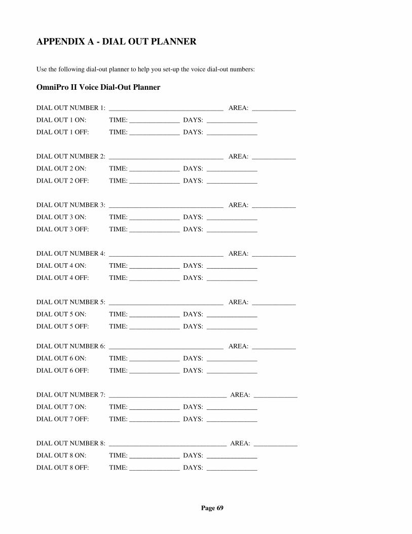
Page 69
APPENDIX A - DIAL OUT PLANNER
Use the following dial-out planner to help you set-up the voice dial-out numbers:
OmniPro II Voice Dial-Out Planner
DIAL OUT NUMBER 1: __________________________________ AREA: _____________
DIAL OUT 1 ON: TIME: _______________ DAYS: _______________
DIAL OUT 1 OFF: TIME: _______________ DAYS: _______________
DIAL OUT NUMBER 2: __________________________________ AREA: _____________
DIAL OUT 2 ON: TIME: _______________ DAYS: _______________
DIAL OUT 2 OFF: TIME: _______________ DAYS: _______________
DIAL OUT NUMBER 3: __________________________________ AREA: _____________
DIAL OUT 3 ON: TIME: _______________ DAYS: _______________
DIAL OUT 3 OFF: TIME: _______________ DAYS: _______________
DIAL OUT NUMBER 4: __________________________________ AREA: _____________
DIAL OUT 4 ON: TIME: _______________ DAYS: _______________
DIAL OUT 4 OFF: TIME: _______________ DAYS: _______________
DIAL OUT NUMBER 5: __________________________________ AREA: _____________
DIAL OUT 5 ON: TIME: _______________ DAYS: _______________
DIAL OUT 5 OFF: TIME: _______________ DAYS: _______________
DIAL OUT NUMBER 6: __________________________________ AREA: _____________
DIAL OUT 6 ON: TIME: _______________ DAYS: _______________
DIAL OUT 6 OFF: TIME: _______________ DAYS: _______________
DIAL OUT NUMBER 7: ___________________________________ AREA: _____________
DIAL OUT 7 ON: TIME: _______________ DAYS: _______________
DIAL OUT 7 OFF: TIME: _______________ DAYS: _______________
DIAL OUT NUMBER 8: ___________________________________ AREA: _____________
DIAL OUT 8 ON: TIME: _______________ DAYS: _______________
DIAL OUT 8 OFF: TIME: _______________ DAYS: _______________
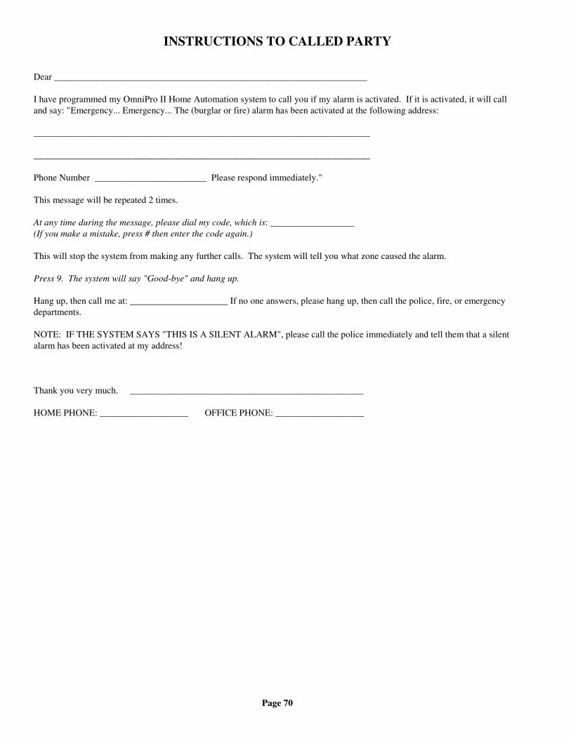
Page 70
INSTRUCTIONS TO CALLED PARTY
Dear ___________________________________________________________________
I have programmed my OmniPro II Home Automation system to call you if my alarm is activated. If it is activated, it will calland say: "Emergency... Emergency... The (burglar or fire) alarm has been activated at the following address:
________________________________________________________________________
________________________________________________________________________
Phone Number ________________________ Please respond immediately."
This message will be repeated 2 times.
At any time during the message, please dial my code, which is: __________________(If you make a mistake, press # then enter the code again.)
This will stop the system from making any further calls. The system will tell you what zone caused the alarm.
Press 9. The system will say "Good-bye" and hang up.
Hang up, then call me at: _____________________ If no one answers, please hang up, then call the police, fire, or emergencydepartments.
NOTE: IF THE SYSTEM SAYS "THIS IS A SILENT ALARM", please call the police immediately and tell them that a silentalarm has been activated at my address!
Thank you very much. __________________________________________________
HOME PHONE: ___________________ OFFICE PHONE: ___________________
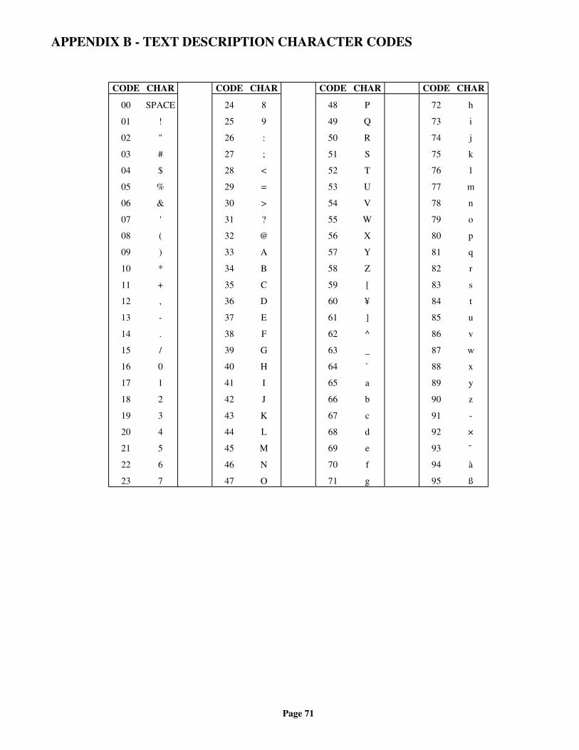
Page 71
APPENDIX B - TEXT DESCRIPTION CHARACTER CODES
CODE CHAR CODE CHAR CODE CHAR CODE CHAR
00
01
02
03
04
05
06
07
08
09
10
11
12
13
14
15
16
17
18
19
20
21
22
23
SPACE
!
"
#
$
%
&
'
(
)
*
+
,
-
.
/
0
1
2
3
4
5
6
7
24
25
26
27
28
29
30
31
32
33
34
35
36
37
38
39
40
41
42
43
44
45
46
47
8
9
:
;
<
=
>
?
@
A
B
C
D
E
F
G
H
I
J
K
L
M
N
O
48
49
50
51
52
53
54
55
56
57
58
59
60
61
62
63
64
65
66
67
68
69
70
71
P
Q
R
S
T
U
V
W
X
Y
Z
[
¥
]
^
_
`
a
b
c
d
e
f
g
72
73
74
75
76
77
78
79
80
81
82
83
84
85
86
87
88
89
90
91
92
93
94
95
h
i
j
k
l
m
n
o
p
q
r
s
t
u
v
w
x
y
z
-
×
¯
à
ß
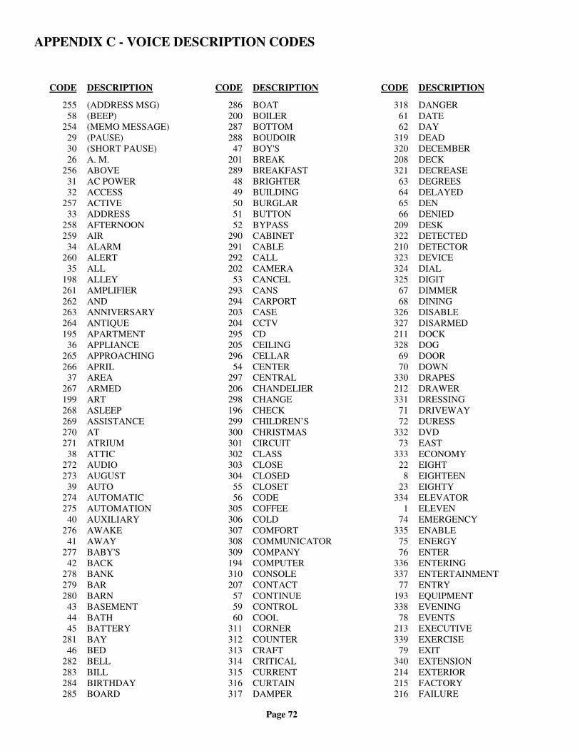
Page 72
APPENDIX C - VOICE DESCRIPTION CODES
CODE DESCRIPTION
255 (ADDRESS MSG)58 (BEEP)
254 (MEMO MESSAGE)29 (PAUSE)30 (SHORT PAUSE)26 A. M.
256 ABOVE31 AC POWER32 ACCESS
257 ACTIVE33 ADDRESS
258 AFTERNOON259 AIR
34 ALARM260 ALERT
35 ALL198 ALLEY261 AMPLIFIER262 AND263 ANNIVERSARY264 ANTIQUE195 APARTMENT
36 APPLIANCE265 APPROACHING266 APRIL
37 AREA267 ARMED199 ART268 ASLEEP269 ASSISTANCE270 AT271 ATRIUM
38 ATTIC272 AUDIO273 AUGUST
39 AUTO274 AUTOMATIC275 AUTOMATION
40 AUXILIARY276 AWAKE
41 AWAY277 BABY'S
42 BACK278 BANK279 BAR280 BARN
43 BASEMENT44 BATH45 BATTERY
281 BAY46 BED
282 BELL283 BILL284 BIRTHDAY285 BOARD
CODE DESCRIPTION
286 BOAT200 BOILER287 BOTTOM288 BOUDOIR
47 BOY'S201 BREAK289 BREAKFAST
48 BRIGHTER49 BUILDING50 BURGLAR51 BUTTON52 BYPASS
290 CABINET291 CABLE292 CALL202 CAMERA
53 CANCEL293 CANS294 CARPORT203 CASE204 CCTV295 CD205 CEILING296 CELLAR
54 CENTER297 CENTRAL206 CHANDELIER298 CHANGE196 CHECK299 CHILDREN’S300 CHRISTMAS301 CIRCUIT302 CLASS303 CLOSE304 CLOSED
55 CLOSET56 CODE
305 COFFEE306 COLD307 COMFORT308 COMMUNICATOR309 COMPANY194 COMPUTER310 CONSOLE207 CONTACT
57 CONTINUE59 CONTROL60 COOL
311 CORNER312 COUNTER313 CRAFT314 CRITICAL315 CURRENT316 CURTAIN317 DAMPER
CODE DESCRIPTION
318 DANGER61 DATE62 DAY
319 DEAD320 DECEMBER208 DECK321 DECREASE
63 DEGREES64 DELAYED65 DEN66 DENIED
209 DESK322 DETECTED210 DETECTOR323 DEVICE324 DIAL325 DIGIT
67 DIMMER68 DINING
326 DISABLE327 DISARMED211 DOCK328 DOG
69 DOOR70 DOWN
330 DRAPES212 DRAWER331 DRESSING
71 DRIVEWAY72 DURESS
332 DVD73 EAST
333 ECONOMY22 EIGHT
8 EIGHTEEN23 EIGHTY
334 ELEVATOR1 ELEVEN
74 EMERGENCY335 ENABLE
75 ENERGY76 ENTER
336 ENTERING337 ENTERTAINMENT
77 ENTRY193 EQUIPMENT338 EVENING
78 EVENTS213 EXECUTIVE339 EXERCISE
79 EXIT340 EXTENSION214 EXTERIOR215 FACTORY216 FAILURE

Page 73
CODE DESCRIPTION
341 FALL80 FAMILY81 FAN
342 FATHER’S343 FAULT344 FEBRUARY217 FENCE
5 FIFTEEN17 FIFTY
218 FILE345 FILTER
82 FIRE219 FIRST
16 FIVE346 FLAG347 FLOOD220 FLOOR221 FLOW348 FORCE
15 FORTY349 FOUNDATION350 FOUNTAIN
14 FOUR4 FOURTEEN
83 FOYER84 FREEZE
351 FREEZER352 FRIDAY353 FROM
85 FRONT354 FULL355 FUNCTION222 FURNACE
86 FUSE223 GALLERY356 GAME
87 GARAGE357 GARDEN
88 GAS224 GATE
89 GIRL'S90 GLASS
358 GO92 GO TO
359 GOOD91 GOOD-BYE
360 GOT361 GREAT362 GROUNDS363 GROUP364 GUARD
93 GUEST94 GUN
365 GYM95 HAD96 HALL
366 HAPPY367 HARBOR368 HAVE
97 HEAT
CODE DESCRIPTION
369 HELLO370 HELP
98 HIGH371 HIGHER372 HOBBY
99 HOLD373 HOLIDAY374 HOME375 HOT100 HOURS376 HOUSE377 HUMIDITY101 HUNDRED378 IMMEDIATELY379 IN380 INCREASE225 INFRARED381 INPUT226 INSIDE102 INSTANT103 INTERIOR382 INTERNET227 INTRUSION104 INVALID105 IS383 JACUZZI384 JANUARY385 JEWELRY386 JULY387 JUNE388 KEEPER389 KENNEL390 KEY106 KITCHEN228 LAMP391 LANAI392 LAND393 LANDSCAPE394 LASER DISK395 LAST396 LAUNCH397 LAUNDRY398 LAWN399 LEAK400 LEAVE107 LEFT108 LEVEL401 LIBRARY402 LIFT109 LIGHT403 LIGHTING404 LIGHTS110 LISTEN405 LIVE111 LIVING229 LOADING406 LOBBY230 LOCK407 LOFT112 LOW
CODE DESCRIPTION
408 LOWER231 MACHINE409 MAID'S410 MAIL113 MAIN411 MANAGEMENT412 MANAGER413 MARCH114 MASTER414 MAT415 MAY416 MECHANICAL115 MEDICAL417 MEDICATION418 MEETING419 MENU197 MESSAGE420 METER421 MID422 MIDDLE423 MIDNIGHT116 MINUS117 MINUTES424 MOBILE118 MODE425 MODEM426 MODULE427 MONDAY232 MONITOR428 MONTH429 MORNING430 MOTHER’S119 MOTION431 MOVIE432 MUD433 MUSIC434 MUTE435 NANNY436 NEXT120 NIGHT
24 NINE9 NINETEEN
25 NINETY437 NO438 NOOK439 NOON121 NORTH122 NOT440 NOVEMBER123 NOW124 NUMBER125 NURSERY441 NURSE'S442 O’CLOCK443 OCTOBER126 OFF127 OFFICE128 OH129 ON130 ONE

Page 74
CODE DESCRIPTION
444 ONLINE445 ONLY233 OPEN446 OPTION131 OR447 OTHER448 OUT132 OUTDOOR133 OUTLET449 OUTSIDE450 OVER234 OVERFLOW235 OVERHEAD
27 P. M.134 PANIC451 PANTRY452 PARKING453 PARLOR454 PARTY135 PATIO455 PAUSE136 PC137 PERIMETER456 PERSONNEL457 PET138 PHONE458 PHRASE459 PIER460 PLACE461 PLANTS139 PLAY140 PLEASE CHOOSE462 PLUS141 POINT142 POLICE143 POOL144 PORCH463 POSITION464 POT145 POUND465 PRECIOUS146 PRESS466 PRESSURE467 PROGRAM468 PROTECTED147 PUMP469 QUARTERS470 RAIN471 RAISE472 READING148 READY236 REAR149 RECORD473 RECREATION474 RECYCLE150 REMOTE151 REPEAT475 RESIDENCE152 RESTORE476 RESTRICTED
CODE DESCRIPTION
153 RIGHT154 RISE477 ROMANTIC237 ROOF155 ROOM478 RUN238 SAFE479 SAFETY239 SATELLITE480 SATURDAY481 SAUNA156 SAVER482 SCENE483 SCHOOL484 SCREEN240 SECOND157 SECONDS158 SECURE159 SECURITY485 SEND241 SENSOR486 SEPTEMBER487 SERVICE488 SET160 SETTING
20 SEVEN7 SEVENTEEN
21 SEVENTY489 SEWING490 SHADES491 SHED492 SHOCK161 SHOP493 SHOW494 SHUTTERS162 SIDE163 SILENT
18 SIX6 SIXTEEN
19 SIXTY495 SKYLIGHT496 SLIDING497 SMART242 SMOKE498 SNOW164 SOUTH165 SPA499 SPARE500 SPOT501 SPRING243 SPRINKLER502 STABLE166 STAIRS503 STAIRWELL167 STAR244 STATION168 STATUS169 STEPS191 STOCK170 STORAGE
CODE DESCRIPTION
245 STORE504 STUDIO505 STUDY506 SUITE507 SUMMER508 SUMP171 SUN509 SUNDAY510 SWITCH172 SYSTEM OK511 TABLE173 TALK174 TAMPER512 TAPE513 TEEN246 TELLER175 TEMPERATURE514 TEMPORARY176 TEN515 TENANT516 THANK YOU517 THEATER177 THEN178 THERMOSTAT247 THIRD
3 THIRTEEN13 THIRTY12 THREE
518 THURSDAY179 TIME180 TIMED519 TIMER181 TO520 TOOL521 TOP522 TOUCHSCREEN523 TRACK524 TRANSMITTER248 TRAP525 TRASH526 TREE183 TRIPPED182 TROUBLE527 TUB528 TUESDAY529 TUNER530 TV
2 TWELVE11 TWENTY10 TWO
531 TYPE532 UNDER184 UNIT185 UP533 UPPER534 USER192 UTILITY186 VACATION249 VALVE535 VANITY
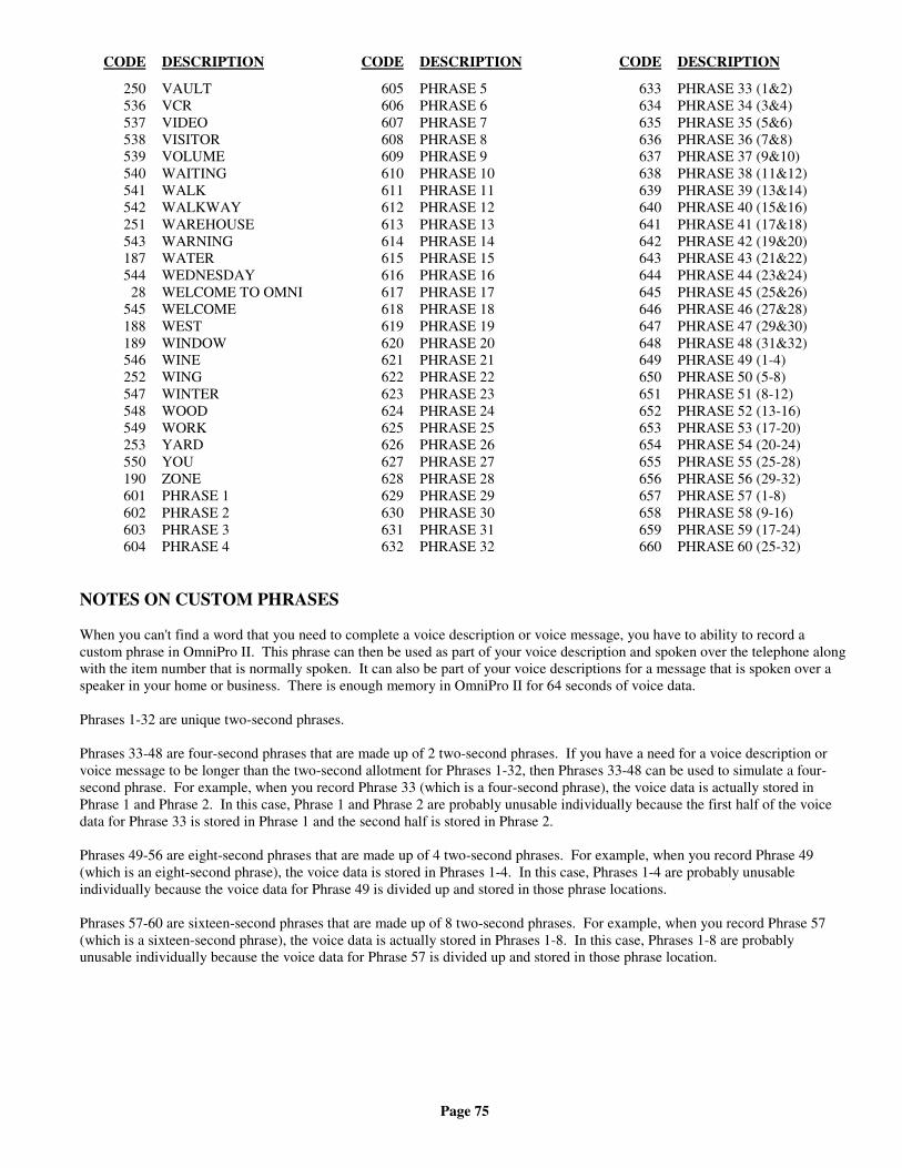
Page 75
CODE DESCRIPTION
250 VAULT536 VCR537 VIDEO538 VISITOR539 VOLUME540 WAITING541 WALK542 WALKWAY251 WAREHOUSE543 WARNING187 WATER544 WEDNESDAY
28 WELCOME TO OMNI545 WELCOME188 WEST189 WINDOW546 WINE252 WING547 WINTER548 WOOD549 WORK253 YARD550 YOU190 ZONE601 PHRASE 1602 PHRASE 2603 PHRASE 3604 PHRASE 4
CODE DESCRIPTION
605 PHRASE 5606 PHRASE 6607 PHRASE 7608 PHRASE 8609 PHRASE 9610 PHRASE 10611 PHRASE 11612 PHRASE 12613 PHRASE 13614 PHRASE 14615 PHRASE 15616 PHRASE 16617 PHRASE 17618 PHRASE 18619 PHRASE 19620 PHRASE 20621 PHRASE 21622 PHRASE 22623 PHRASE 23624 PHRASE 24625 PHRASE 25626 PHRASE 26627 PHRASE 27628 PHRASE 28629 PHRASE 29630 PHRASE 30631 PHRASE 31632 PHRASE 32
CODE DESCRIPTION
633 PHRASE 33 (1&2)634 PHRASE 34 (3&4)635 PHRASE 35 (5&6)636 PHRASE 36 (7&8)637 PHRASE 37 (9&10)638 PHRASE 38 (11&12)639 PHRASE 39 (13&14)640 PHRASE 40 (15&16)641 PHRASE 41 (17&18)642 PHRASE 42 (19&20)643 PHRASE 43 (21&22)644 PHRASE 44 (23&24)645 PHRASE 45 (25&26)646 PHRASE 46 (27&28)647 PHRASE 47 (29&30)648 PHRASE 48 (31&32)649 PHRASE 49 (1-4)650 PHRASE 50 (5-8)651 PHRASE 51 (8-12)652 PHRASE 52 (13-16)653 PHRASE 53 (17-20)654 PHRASE 54 (20-24)655 PHRASE 55 (25-28)656 PHRASE 56 (29-32)657 PHRASE 57 (1-8)658 PHRASE 58 (9-16)659 PHRASE 59 (17-24)660 PHRASE 60 (25-32)
NOTES ON CUSTOM PHRASES
When you can't find a word that you need to complete a voice description or voice message, you have to ability to record acustom phrase in OmniPro II. This phrase can then be used as part of your voice description and spoken over the telephone alongwith the item number that is normally spoken. It can also be part of your voice descriptions for a message that is spoken over aspeaker in your home or business. There is enough memory in OmniPro II for 64 seconds of voice data.
Phrases 1-32 are unique two-second phrases.
Phrases 33-48 are four-second phrases that are made up of 2 two-second phrases. If you have a need for a voice description orvoice message to be longer than the two-second allotment for Phrases 1-32, then Phrases 33-48 can be used to simulate a four-second phrase. For example, when you record Phrase 33 (which is a four-second phrase), the voice data is actually stored inPhrase 1 and Phrase 2. In this case, Phrase 1 and Phrase 2 are probably unusable individually because the first half of the voicedata for Phrase 33 is stored in Phrase 1 and the second half is stored in Phrase 2.
Phrases 49-56 are eight-second phrases that are made up of 4 two-second phrases. For example, when you record Phrase 49(which is an eight-second phrase), the voice data is stored in Phrases 1-4. In this case, Phrases 1-4 are probably unusableindividually because the voice data for Phrase 49 is divided up and stored in those phrase locations.
Phrases 57-60 are sixteen-second phrases that are made up of 8 two-second phrases. For example, when you record Phrase 57(which is a sixteen-second phrase), the voice data is actually stored in Phrases 1-8. In this case, Phrases 1-8 are probablyunusable individually because the voice data for Phrase 57 is divided up and stored in those phrase location.


NOTE TO INSTALLER
Following installation, this manual shall be left for the homeowner's use.
HAI • New Orleans, LA • U S A