Embed Size (px)
Citation preview
30081N-2 05/29/14 REV J PCN3723 ©2011, 2014 CEQUENT PERFORMANCE PRODUCTS, INC PRINTED IN MEXICO
FOR KITS: 30081, 40261 & 50181
For Installation Assistance or Technical Help, Call 1-888-521-0510
(1) Provide this Manual to end user.
(2) Physically demonstrate hitching and unhitching
procedures in this Manual to end user.
(3) Have end user demonstrate that he/she
understands procedures.
DEALER/INSTALLER: END USER:
(1) Read and follow this Manual every time you use hitch.
(2) Save this Manual and Hitch Warning Hang Tag for future reference.
(3) Pass on copies of Manual and Hitch Warning Hang Tag to any other
user or owner of hitch.
(4) Never remove hitch warning decals as shown on the cover of this
manual. If damaged, contact Cequent Performance Products (1-
800-632-3290) for free replacement.
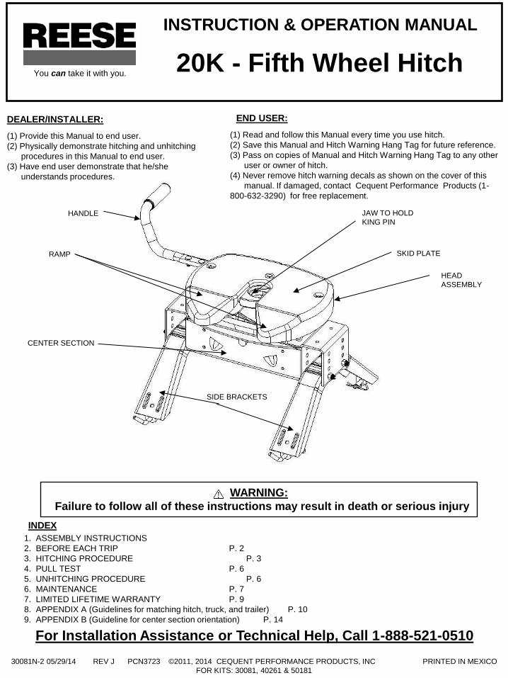
INSTRUCTION & OPERATION MANUAL
JAW TO HOLD
KING PIN
SKID PLATE
HANDLE
RAMP
CENTER SECTION
SIDE BRACKETS
HEAD
ASSEMBLY
WARNING:
Failure to follow all of these instructions may result in death or serious injury
1. ASSEMBLY INSTRUCTIONS
2. BEFORE EACH TRIP P. 2
3. HITCHING PROCEDURE P. 3
4. PULL TEST P. 6
5. UNHITCHING PROCEDURE P. 6
6. MAINTENANCE P. 7
7. LIMITED LIFETIME WARRANTY P. 9
8. APPENDIX A (Guidelines for matching hitch, truck, and trailer) P. 10
9. APPENDIX B (Guideline for center section orientation) P. 14
INDEX
20K - Fifth Wheel Hitch You can take it with you.
30081N-2 05/29/14 REV J PCN3723 ©2011, 2014 CEQUENT PERFORMANCE PRODUCTS, INC PRINTED IN MEXICO
FOR KITS: 30081, 40261 & 50181
2
1. Reference Fig. 11 on page 8.
2. 5th Wheel Kit is contained in three cartons. Unpack and become familiar with parts on parts list. Base rails, brackets and
hardware are in separate kit (part no. 30035) with separate Installation Instructions for Fifth Wheel Rail Mounting Kit.
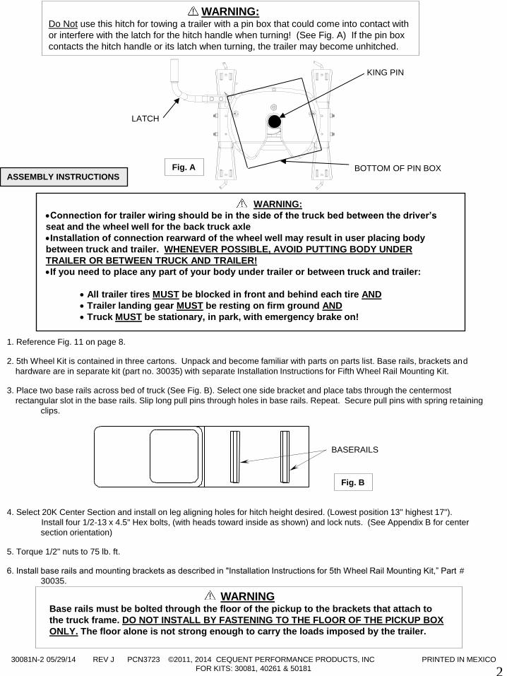
3. Place two base rails across bed of truck (See Fig. B). Select one side bracket and place tabs through the centermost
rectangular slot in the base rails. Slip long pull pins through holes in base rails. Repeat. Secure pull pins with spring retaining
clips.
4. Select 20K Center Section and install on leg aligning holes for hitch height desired. (Lowest position 13" highest 17").
Install four 1/2-13 x 4.5" Hex bolts, (with heads toward inside as shown) and lock nuts. (See Appendix B for center
section orientation)
5. Torque 1/2" nuts to 75 lb. ft.
6. Install base rails and mounting brackets as described in "Installation Instructions for 5th Wheel Rail Mounting Kit,” Part #
30035.
ASSEMBLY INSTRUCTIONS
WARNING:
Connection for trailer wiring should be in the side of the truck bed between the driver’s
seat and the wheel well for the back truck axle
Installation of connection rearward of the wheel well may result in user placing body
between truck and trailer. WHENEVER POSSIBLE, AVOID PUTTING BODY UNDER
TRAILER OR BETWEEN TRUCK AND TRAILER!
If you need to place any part of your body under trailer or between truck and trailer:
All trailer tires MUST be blocked in front and behind each tire AND
Trailer landing gear MUST be resting on firm ground AND
Truck MUST be stationary, in park, with emergency brake on!
WARNING: Do Not use this hitch for towing a trailer with a pin box that could come into contact with
or interfere with the latch for the hitch handle when turning! (See Fig. A) If the pin box
contacts the hitch handle or its latch when turning, the trailer may become unhitched.
WARNING Base rails must be bolted through the floor of the pickup to the brackets that attach to
the truck frame. DO NOT INSTALL BY FASTENING TO THE FLOOR OF THE PICKUP BOX
ONLY. The floor alone is not strong enough to carry the loads imposed by the trailer.
KING PIN
BOTTOM OF PIN BOX
Fig. B
BASERAILS
LATCH
Fig. A
30081N-2 05/29/14 REV J PCN3723 ©2011, 2014 CEQUENT PERFORMANCE PRODUCTS, INC PRINTED IN MEXICO
FOR KITS: 30081, 40261 & 50181 3
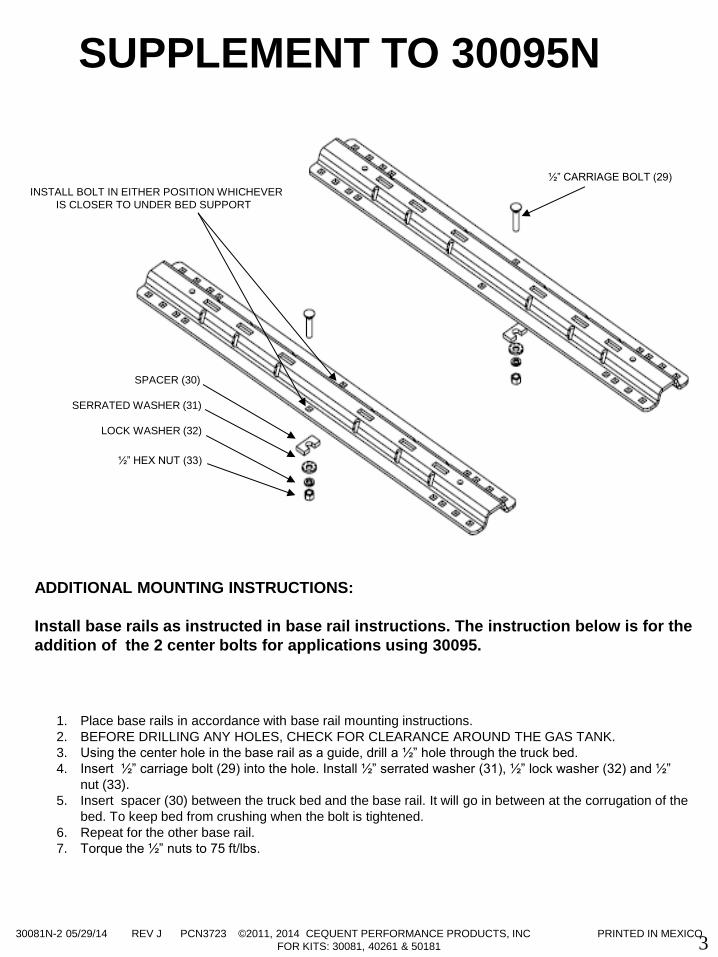
ADDITIONAL MOUNTING INSTRUCTIONS:
Install base rails as instructed in base rail instructions. The instruction below is for the
addition of the 2 center bolts for applications using 30095.
1. Place base rails in accordance with base rail mounting instructions.
2. BEFORE DRILLING ANY HOLES, CHECK FOR CLEARANCE AROUND THE GAS TANK.
3. Using the center hole in the base rail as a guide, drill a ½” hole through the truck bed.
4. Insert ½” carriage bolt (29) into the hole. Install ½” serrated washer (31), ½” lock washer (32) and ½”
nut (33).
5. Insert spacer (30) between the truck bed and the base rail. It will go in between at the corrugation of the
bed. To keep bed from crushing when the bolt is tightened.
6. Repeat for the other base rail.
7. Torque the ½” nuts to 75 ft/lbs.
½” CARRIAGE BOLT (29)
SPACER (30)
SERRATED WASHER (31)
LOCK WASHER (32)
½” HEX NUT (33)
INSTALL BOLT IN EITHER POSITION WHICHEVER
IS CLOSER TO UNDER BED SUPPORT
SUPPLEMENT TO 30095N
30081N-2 05/29/14 REV J PCN3723 ©2011, 2014 CEQUENT PERFORMANCE PRODUCTS, INC PRINTED IN MEXICO
FOR KITS: 30081, 40261 & 50181
4
GUIDELINES FOR MATCHING HITCH TRUCK AND TRAILER
If preparing to tow a 5th wheel trailer which you have not rating checked previously, please
consult Appendix A of 5th Wheel Kit assembly instructions.
BEFORE EACH TRIP:
1. Lubricate skid plate surface of the hitch and pivot pin grease fitting (see Figure on cover of Manual) with automotive type
chassis grease or use a plastic lube plate to provide a lubricated surface. Use lithium grease to lubricate pivot points of
moving parts within the hitch.
2. Plastic lube plates (Performance Products No. 83001/40001) can be used to avoid messy grease. The plastic lube plate
must not exceed 3/16 of an inch in thickness to ensure hitch will operate properly. Lube plates must be 12 inches in
diameter or larger to properly distribute king pin weight.
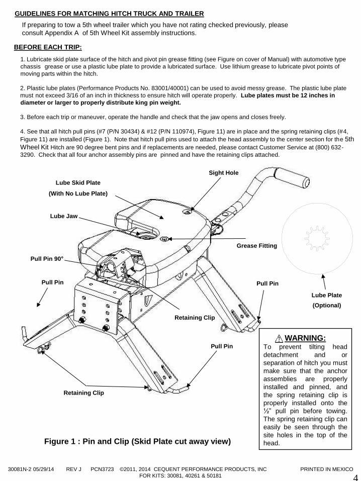
3. Before each trip or maneuver, operate the handle and check that the jaw opens and closes freely.
4. See that all hitch pull pins (#7 (P/N 30434) & #12 (P/N 110974), Figure 11) are in place and the spring retaining clips (#4,
Figure 11) are installed (Figure 1). Note that hitch pull pins used to attach the head assembly to the center section for the 5th
Wheel Kit Hitch are 90 degree bent pins and if replacements are needed, please contact Customer Service at (800) 632-
3290. Check that all four anchor assembly pins are pinned and have the retaining clips attached.
Figure 1 : Pin and Clip (Skid Plate cut away view)
WARNING: To prevent tilting head
detachment and or
separation of hitch you must
make sure that the anchor
assemblies are properly
installed and pinned, and
the spring retaining clip is
properly installed onto the
½” pull pin before towing.
The spring retaining clip can
easily be seen through the
site holes in the top of the
head.
Lube Skid Plate
(With No Lube Plate)
Grease Fitting
Lube Jaw
Retaining Clip
Pull Pin 90°
Retaining Clip
Pull Pin
Pull Pin
Pull Pin
Lube Plate
(Optional)
Sight Hole
30081N-2 05/29/14 REV J PCN3723 ©2011, 2014 CEQUENT PERFORMANCE PRODUCTS, INC PRINTED IN MEXICO
FOR KITS: 30081, 40261 & 50181
5
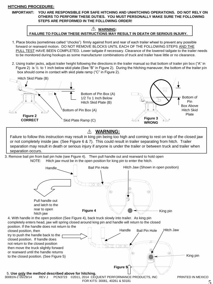
4. With handle in the open position (See Figure 4), back truck slowly into trailer. As king pin
completely enters head, jaw will spring closed around king pin and handle will return to the closed
position. If the handle does not return to the
closed position, then
try to push the handle back to the
closed position. If handle does
not return to the closed position
then move the truck slightly forward
or rearward until the handle returns
to the closed position. (See Figure 5)
5. Use only the method described above for hitching.
Figure 2
CORRECT
Bottom of Pin Box (A)
1/2 To 1 Inch Below
Hitch Skid Plate (B)
Skid Plate Ramp (C)
Hitch Skid Plate (B)
Bottom of Pin Box (A)
IMPORTANT: YOU ARE RESPONSIBLE FOR SAFE HITCHING AND UNHITCHING OPERATIONS. DO NOT RELY ON
OTHERS TO PERFORM THESE DUTIES. YOU MUST PERSONALLY MAKE SURE THE FOLLOWING
STEPS ARE PERFORMED IN THE FOLLOWING ORDER!
WARNING:
FAILURE TO FOLLOW THESE INSTRUCTIONS MAY RESULT IN DEATH OR SERIOUS INJURY.
1. Place blocks (sometimes called “chocks”) firmly against front and rear of each trailer wheel to prevent any possible
forward or rearward motion. DO NOT REMOVE BLOCKS UNTIL EACH OF THE FOLLOWING STEPS AND THE
PULL TEST HAVE BEEN COMPLETED. Lower tailgate if necessary. Clearance of the lowered tailgate to the trailer needs
to be monitored during hookups as some manufacturer combinations of truck and trailer have little or no clearance.
2. Using trailer jacks, adjust trailer height following the directions in the trailer manual so that bottom of trailer pin box (“A” in
Figure 2) is ½ to 1 inch below skid plate (See “B” in Figure 2). During the hitching maneuver, the bottom of the trailer p in
box should come in contact with skid plate ramp (“C” in Figure 2).
HITCHING PROCEDURE:
Bottom of
Pin
Box Above
Hitch Skid
Plate Figure 3
WRONG
WARNING: Failure to follow this instruction may result in king pin being too high and coming to rest on top of the closed jaw
or not completely inside jaw. (See Figure 6 & 7). This could result in trailer separating from hitch. Trailer
separation may result in death or serious injury if anyone is under the trailer or between truck and trailer when
separation occurs.
3. Remove bail pin from bail pin hole (see Figure 4). Then pull handle out and rearward to hold open
NOTE: Hitch jaw must be in the open position for king pin to enter the hitch.
Figure 4 King pin
Pull handle out
and latch to the
rear to open
hitch jaw
Hitch Jaw (Shown in open position) Handle Bail Pin Hole
Figure 5
King pin
Hitch Jaw Handle Bail Pin Hole
30081N-2 05/29/14 REV J PCN3723 ©2011, 2014 CEQUENT PERFORMANCE PRODUCTS, INC PRINTED IN MEXICO
FOR KITS: 30081, 40261 & 50181
6
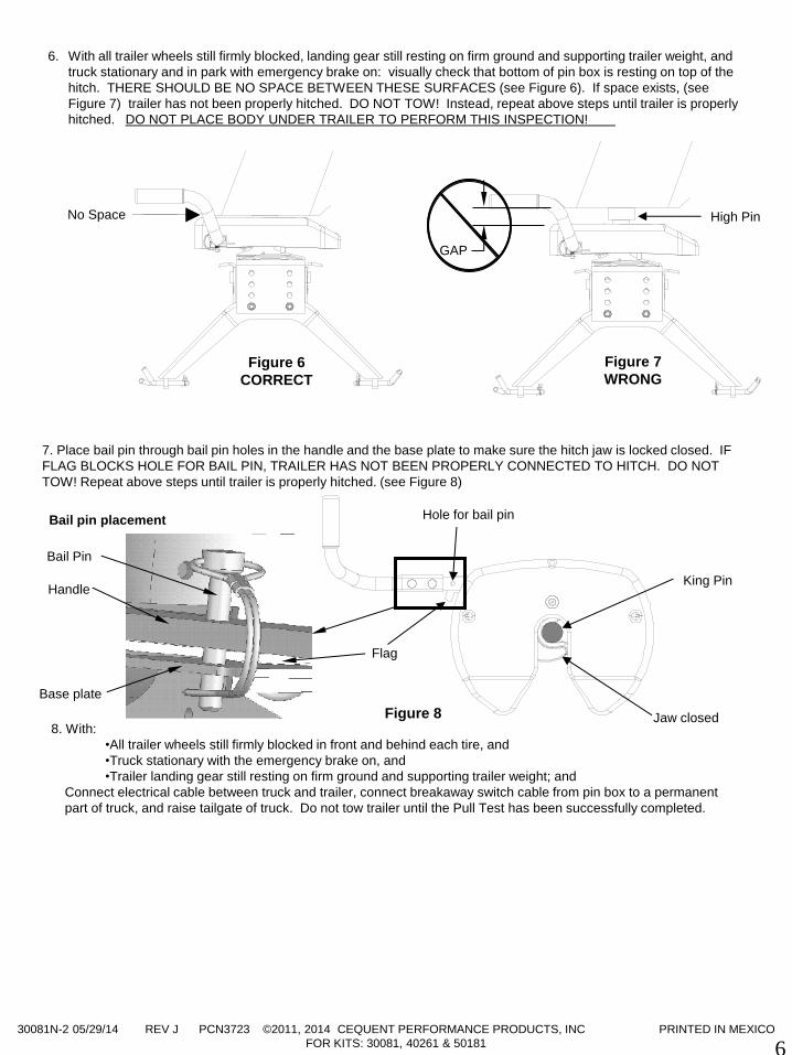
8. With:
•All trailer wheels still firmly blocked in front and behind each tire, and
•Truck stationary with the emergency brake on, and
•Trailer landing gear still resting on firm ground and supporting trailer weight; and
Connect electrical cable between truck and trailer, connect breakaway switch cable from pin box to a permanent
part of truck, and raise tailgate of truck. Do not tow trailer until the Pull Test has been successfully completed.
7. Place bail pin through bail pin holes in the handle and the base plate to make sure the hitch jaw is locked closed. IF
FLAG BLOCKS HOLE FOR BAIL PIN, TRAILER HAS NOT BEEN PROPERLY CONNECTED TO HITCH. DO NOT
TOW! Repeat above steps until trailer is properly hitched. (see Figure 8)
King Pin
Jaw closed Figure 8
Hole for bail pin
Flag
6. With all trailer wheels still firmly blocked, landing gear still resting on firm ground and supporting trailer weight, and
truck stationary and in park with emergency brake on: visually check that bottom of pin box is resting on top of the
hitch. THERE SHOULD BE NO SPACE BETWEEN THESE SURFACES (see Figure 6). If space exists, (see
Figure 7) trailer has not been properly hitched. DO NOT TOW! Instead, repeat above steps until trailer is properly
hitched. DO NOT PLACE BODY UNDER TRAILER TO PERFORM THIS INSPECTION!
Figure 7
WRONG Figure 6
CORRECT
High Pin No Space
GAP
Handle
Base plate
Bail pin placement
Bail Pin
30081N-2 05/29/14 REV J PCN3723 ©2011, 2014 CEQUENT PERFORMANCE PRODUCTS, INC PRINTED IN MEXICO
FOR KITS: 30081, 40261 & 50181
7
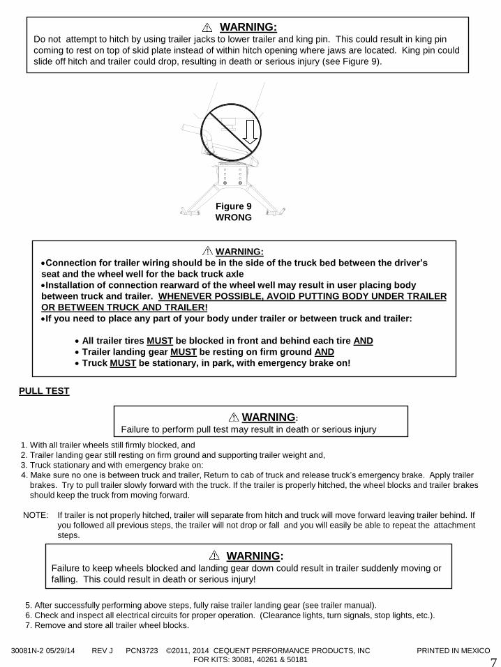
WARNING: Do not attempt to hitch by using trailer jacks to lower trailer and king pin. This could result in king pin
coming to rest on top of skid plate instead of within hitch opening where jaws are located. King pin could
slide off hitch and trailer could drop, resulting in death or serious injury (see Figure 9).
1. With all trailer wheels still firmly blocked, and
2. Trailer landing gear still resting on firm ground and supporting trailer weight and,
3. Truck stationary and with emergency brake on:
4. Make sure no one is between truck and trailer, Return to cab of truck and release truck’s emergency brake. Apply trailer
brakes. Try to pull trailer slowly forward with the truck. If the trailer is properly hitched, the wheel blocks and trailer brakes
should keep the truck from moving forward.
NOTE: If trailer is not properly hitched, trailer will separate from hitch and truck will move forward leaving trailer behind. If
you followed all previous steps, the trailer will not drop or fall and you will easily be able to repeat the attachment
steps.
5. After successfully performing above steps, fully raise trailer landing gear (see trailer manual).
6. Check and inspect all electrical circuits for proper operation. (Clearance lights, turn signals, stop lights, etc.).
7. Remove and store all trailer wheel blocks.
PULL TEST
WARNING: Failure to keep wheels blocked and landing gear down could result in trailer suddenly moving or
falling. This could result in death or serious injury!
WARNING:
Failure to perform pull test may result in death or serious injury
WARNING:
Connection for trailer wiring should be in the side of the truck bed between the driver’s
seat and the wheel well for the back truck axle
Installation of connection rearward of the wheel well may result in user placing body
between truck and trailer. WHENEVER POSSIBLE, AVOID PUTTING BODY UNDER TRAILER
OR BETWEEN TRUCK AND TRAILER!
If you need to place any part of your body under trailer or between truck and trailer:
All trailer tires MUST be blocked in front and behind each tire AND
Trailer landing gear MUST be resting on firm ground AND
Truck MUST be stationary, in park, with emergency brake on!
Figure 9
WRONG
30081N-2 05/29/14 REV J PCN3723 ©2011, 2014 CEQUENT PERFORMANCE PRODUCTS, INC PRINTED IN MEXICO
FOR KITS: 30081, 40261 & 50181
8
PERFORM THE FOLLOWING IN THIS ORDER:
1. Make sure truck is in park with emergency brake on.
2. Place blocks firmly against front and rear of each trailer wheel to prevent any possible forward or rearward motion.
3. Using trailer jacks, lower trailer landing gear following the directions in the Trailer Manual until feet of landing gear are
resting on firm ground.
4. Lower truck tail gate.
5. Disconnect power cable and breakaway switch cable between truck and trailer.
6. Remove bail pin from hole in handle.
7. Pull hitch handle out completely until it latches in open position so that king pin is no longer
securely grasped by hitch jaws (see Figure 4). Trailer is now free from hitch and truck. If handle does not pull out,
there is probably pressure against the jaw. To relieve this pressure, back the truck slightly or pull the truck slightly
forward. Reset truck emergency brake. Then pull hitch handle out completely until it latches in open position.
8. AFTER MAKING CERTAIN NO ONE IS STANDING BETWEEN TRUCK AND TRAILER OR IN FRONT OF TRUCK,
drive truck slowly away from trailer.
9. Hitch jaw will automatically close as the king pin is removed from the jaw.
10. KEEP WHEEL BLOCKS IN PLACE. This will keep trailer from moving unexpectedly
1. Recheck tightness of all hardware every 1000 miles of use. All 1/2” bolts have a torque specification of
75ft.lbs.
2. See “Before each trip” section in this manual.
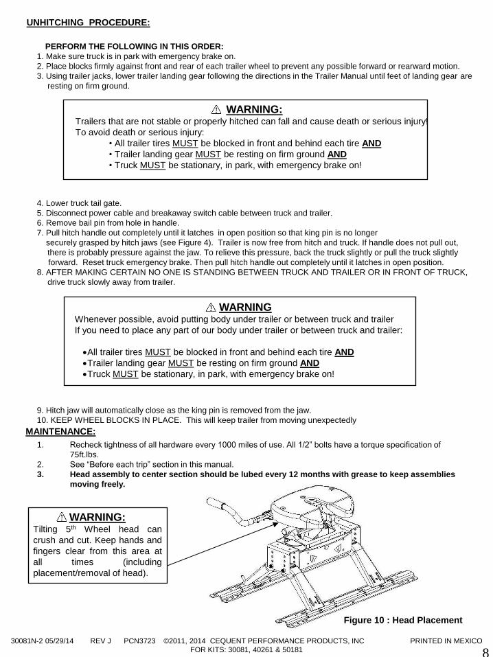
3. Head assembly to center section should be lubed every 12 months with grease to keep assemblies
moving freely.
MAINTENANCE:
WARNING Whenever possible, avoid putting body under trailer or between truck and trailer
If you need to place any part of our body under trailer or between truck and trailer:
All trailer tires MUST be blocked in front and behind each tire AND
Trailer landing gear MUST be resting on firm ground AND
Truck MUST be stationary, in park, with emergency brake on!
UNHITCHING PROCEDURE:
WARNING:
Trailers that are not stable or properly hitched can fall and cause death or serious injury!
To avoid death or serious injury:
• All trailer tires MUST be blocked in front and behind each tire AND
• Trailer landing gear MUST be resting on firm ground AND
• Truck MUST be stationary, in park, with emergency brake on!
WARNING: Tilting 5th Wheel head can
crush and cut. Keep hands and
fingers clear from this area at
all times (including
placement/removal of head).
Figure 10 : Head Placement
30081N-2 05/29/14 REV J PCN3723 ©2011, 2014 CEQUENT PERFORMANCE PRODUCTS, INC PRINTED IN MEXICO
FOR KITS: 30081, 40261 & 50181
9
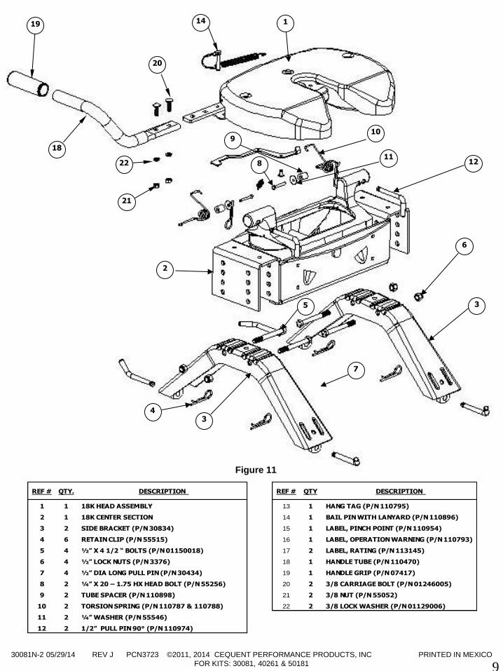
Figure 11
1
3
3
4
5
6
7
8 11
9
12
2
14
10
19
18
20
22
21
REF # QTY. DESCRIPTION REF # QTY DESCRIPTION
1 1 18K HEAD ASSEMBLY 13 1 HANG TAG (P/N 110795)
2 1 18K CENTER SECTION 14 1 BAIL PIN WITH LANYARD (P/N 110896)
3 2 SIDE BRACKET (P/N 30834) 15 1 LABEL, PINCH POINT (P/N 110954)
4 6 RETAIN CLIP (P/N 55515) 16 1 LABEL, OPERATION WARNING (P/N 110793)
5 4 ½” X 4 1/2 “ BOLTS (P/N 01150018) 17 2 LABEL, RATING (P/N 113145)
6 4 ½” LOCK NUTS (P/N 3376) 18 1 HANDLE TUBE (P/N 110470)
7 4 ½” DIA LONG PULL PIN (P/N 30434) 19 1 HANDLE GRIP (P/N 07417)
8 2 ¼” X 20 – 1.75 HX HEAD BOLT (P/N 55256) 20 2 3/8 CARRIAGE BOLT (P/N 01246005)
9 2 TUBE SPACER (P/N 110898) 21 2 3/8 NUT (P/N 55052)
10 2 TORSION SPRING (P/N 110787 & 110788) 22 2 3/8 LOCK WASHER (P/N 01129006)
11 2 ¼” WASHER (P/N 55546)
12 2 1/2” PULL PIN 90° (P/N 110974)
30081N-2 05/29/14 REV J PCN3723 ©2011, 2014 CEQUENT PERFORMANCE PRODUCTS, INC PRINTED IN MEXICO
FOR KITS: 30081, 40261 & 50181
10
NOTES
LIMITED LIFETIME WARRANTY
Part No:_____________________________________ Original Purchase:____________________________
Original Owner:_______________________________ Original Installer:_____________________________
1. Limited Lifetime Warranty (“Warranty”). Cequent Performance Products, Inc. ("We" or “Us”) warrants to the original
consumer purchaser only ("You") that the product will be free from material defects in both material and workmanship,
ordinary wear and tear excepted; provided that installation and use of the product is in accordance with product instructions.
There are no other warranties, express or implied, including the warranty of merchantability or fitness for a particular purpose.
This warranty is not transferable.
2. Limitations on the Warranty. This Warranty does not cover: (a) normal wear and tear; (b) damage through abuse, neglect,
misuse, or as a result of any accident or in any other manner; (c) damage from misapplication, overloading, or improper
installation; (d) improper maintenance and repair; and (e) product alteration in any manner by anyone other than Us, with the
sole exception of alterations made pursuant to product instructions and in a workmanlike manner.
3. Obligations of Purchaser. To make a Warranty claim, contact Us, at our principal address of 47912 Halyard Dr. Suite 100,
Plymouth, MI 48170, 1-888-521-0510, identify the product by model number, and follow the claim instructions that will be
provided. Any returned product that is replaced by Us becomes our property. You will be responsible for return shipping costs.
Please retain your purchase receipt to verify date of purchase and that You are the original consumer purchaser. The product
and the purchase receipt must be provided to Us in order to process Your Warranty claim.
4. Remedy Limits. Product replacement is Your sole remedy under this Warranty. We shall not be liable for service or labor
charges incurred in removing or replacing a product or any incidental or consequential damages of any kind.
5. Assumption of Risk. You acknowledge and agree that any use of the product for any purpose other than the specified
use(s) stated in the product instructions is at Your own risk.
6. Governing Law. This Warranty gives You specific legal rights, and You also may have other rights which vary from state to
state. This Warranty is governed by the laws of the State of Michigan, without regard to rules pertaining to conflicts of law. The
state courts located in Oakland County, Michigan shall have exclusive jurisdiction for any disputes relating to this Warranty.
Cequent Performance Products, Inc.
47912 Halyard Dr. Suite 100
Plymouth, MI 48170

30081N-2 05/29/14 REV J PCN3723 ©2011, 2014 CEQUENT PERFORMANCE PRODUCTS, INC PRINTED IN MEXICO
FOR KITS: 30081, 40261 & 50181
11
Appendix A
GUIDELINES FOR MATCHING HITCH, TRUCK, AND TRAILER
30081N-2 05/29/14 REV J PCN3723 ©2011, 2014 CEQUENT PERFORMANCE PRODUCTS, INC PRINTED IN MEXICO
FOR KITS: 30081, 40261 & 50181
12
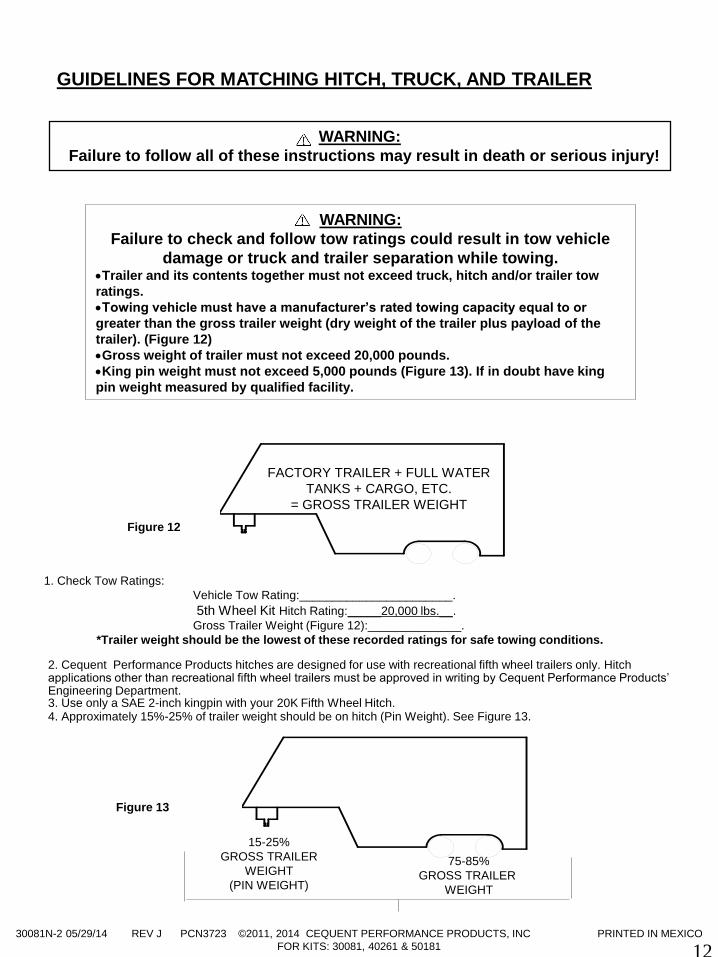
1. Check Tow Ratings:
Vehicle Tow Rating:_______________________.
5th Wheel Kit Hitch Rating:_____20,000 lbs.__.
Gross Trailer Weight (Figure 12):______________.
*Trailer weight should be the lowest of these recorded ratings for safe towing conditions. 2. Cequent Performance Products hitches are designed for use with recreational fifth wheel trailers only. Hitch applications other than recreational fifth wheel trailers must be approved in writing by Cequent Performance Products’ Engineering Department. 3. Use only a SAE 2-inch kingpin with your 20K Fifth Wheel Hitch. 4. Approximately 15%-25% of trailer weight should be on hitch (Pin Weight). See Figure 13.
FACTORY TRAILER + FULL WATER
TANKS + CARGO, ETC.
= GROSS TRAILER WEIGHT
Figure 12
15-25%
GROSS TRAILER
WEIGHT
(PIN WEIGHT)
75-85%
GROSS TRAILER
WEIGHT
Figure 13
GUIDELINES FOR MATCHING HITCH, TRUCK, AND TRAILER
WARNING:
Failure to follow all of these instructions may result in death or serious injury!
WARNING:
Failure to check and follow tow ratings could result in tow vehicle
damage or truck and trailer separation while towing. Trailer and its contents together must not exceed truck, hitch and/or trailer tow
ratings.
Towing vehicle must have a manufacturer’s rated towing capacity equal to or
greater than the gross trailer weight (dry weight of the trailer plus payload of the
trailer). (Figure 12)
Gross weight of trailer must not exceed 20,000 pounds.
King pin weight must not exceed 5,000 pounds (Figure 13). If in doubt have king
pin weight measured by qualified facility.
30081N-2 05/29/14 REV J PCN3723 ©2011, 2014 CEQUENT PERFORMANCE PRODUCTS, INC PRINTED IN MEXICO
FOR KITS: 30081, 40261 & 50181
13
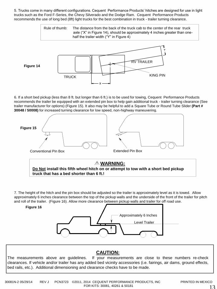
5. Trucks come in many different configurations. Cequent Performance Products’ hitches are designed for use in light
trucks such as the Ford F-Series, the Chevy Silverado and the Dodge Ram. Cequent Performance Products
recommends the use of long bed (8ft) light trucks for the best combination in truck - trailer turning clearance.
6. If a short bed pickup (less than 8 ft. but longer than 6 ft.) is to be used for towing, Cequent Performance Products
recommends the trailer be equipped with an extended pin box to help gain additional truck - trailer turning clearance (See
trailer manufacturer for options) (Figure 15). It also may be helpful to add a Square Tube or Round Tube Slider (Part #
30048 / 50008) for increased turning clearance for low speed, non-highway maneuvering.
7. The height of the hitch and the pin box should be adjusted so the trailer is approximately level as it is towed. Allow
approximately 6 inches clearance between the top of the pickup walls and the underside of the front of the trailer for pitch
and roll of the trailer. (Figure 16). Allow more clearance between pickup walls and trailer for off road use.
KING PIN
RV TRAILER
TRUCK
Figure 14
Conventional Pin Box Extended Pin Box
Figure 15
Rule of thumb: The distance from the back of the truck cab to the center of the rear truck
axle (“X” in Figure 14), should be approximately 4 inches greater than one-
half the trailer width (“Y” in Figure 4)
Approximately 6 Inches
Level Trailer
Figure 16
WARNING: Do Not install this fifth wheel hitch on or attempt to tow with a short bed pickup
truck that has a bed shorter than 6 ft.!
CAUTION: The measurements above are guidelines. If your measurements are close to these numbers re-check
clearances. If vehicle and/or trailer has any added bed vicinity accessories (i.e. fairings, air dams, ground effects,
bed rails, etc.). Additional dimensioning and clearance checks have to be made.
30081N-2 05/29/14 REV J PCN3723 ©2011, 2014 CEQUENT PERFORMANCE PRODUCTS, INC PRINTED IN MEXICO
FOR KITS: 30081, 40261 & 50181
14
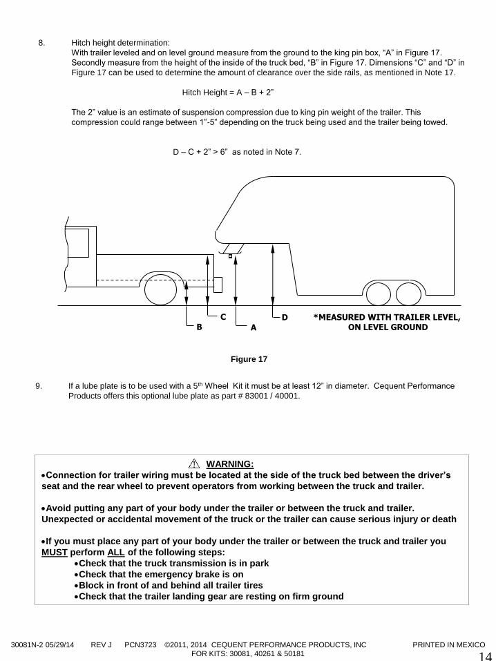
8. Hitch height determination:
With trailer leveled and on level ground measure from the ground to the king pin box, “A” in Figure 17.
Secondly measure from the height of the inside of the truck bed, “B” in Figure 17. Dimensions “C” and “D” in
Figure 17 can be used to determine the amount of clearance over the side rails, as mentioned in Note 17.
Hitch Height = A – B + 2”
The 2” value is an estimate of suspension compression due to king pin weight of the trailer. This
compression could range between 1”-5” depending on the truck being used and the trailer being towed.
D – C + 2” > 6” as noted in Note 7.
B D C
A
*MEASURED WITH TRAILER LEVEL, ON LEVEL GROUND
WARNING:
Connection for trailer wiring must be located at the side of the truck bed between the driver’s
seat and the rear wheel to prevent operators from working between the truck and trailer.
Avoid putting any part of your body under the trailer or between the truck and trailer.
Unexpected or accidental movement of the truck or the trailer can cause serious injury or death
If you must place any part of your body under the trailer or between the truck and trailer you
MUST perform ALL of the following steps:
Check that the truck transmission is in park
Check that the emergency brake is on
Block in front of and behind all trailer tires
Check that the trailer landing gear are resting on firm ground
9. If a lube plate is to be used with a 5th Wheel Kit it must be at least 12” in diameter. Cequent Performance
Products offers this optional lube plate as part # 83001 / 40001.
Figure 17

30081N-2 05/29/14 REV J PCN3723 ©2011, 2014 CEQUENT PERFORMANCE PRODUCTS, INC PRINTED IN MEXICO
FOR KITS: 30081, 40261 & 50181
15
Appendix B
GUIDELINE FOR CENTER SECTION ORIENTATION
30081N-2 05/29/14 REV J PCN3723 ©2011, 2014 CEQUENT PERFORMANCE PRODUCTS, INC PRINTED IN MEXICO
FOR KITS: 30081, 40261 & 50181
16
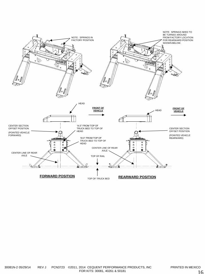
FORWARD POSITION REARWARD POSITION
FRONT OF
VEHICLE FRONT OF
VEHICLE
CENTER LINE OF REAR
AXLE
CENTER LINE OF REAR
AXLE
TOP OF RAIL
NOTE: SPRINGS IN
FACTORY POSITION
NOTE: SPRINGS NEED TO
BE TURNED AROUND
FROM FACTORY LOCATION
FOR REARWARD POSITION
SHOWN BELOW.
CENTER SECTION
OFFSET POSITION
(POINTED VEHICLE
FORWARD)
CENTER SECTION
OFFSET POSITION
(POINTED VEHICLE
REARWARD)
14.5” FROM TOP OF
TRUCK BED TO TOP OF
HEAD
18.0” FROM TOP OF
TRUCK BED TO TOP OF
HEAD
HEAD
HEAD
TOP OF TRUCK BED
50024N – 11/19/14 REV H PCN4441 ©2011, 2014 CEQUENT PERFORMANCE PRODUCTS, INC. Printed in China
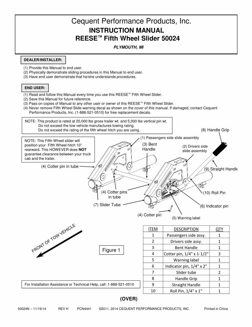
(1) Passengers side slide assembly
(2) Drivers side slide assembly
(5) Warning label
(6) Indicator pin(7) Slider Tube
(4) Cotter pinsin tube
(4) Cotter pin
(8) Handle Grip
(4) Cotter pin in tube(9) Straight Handle
(10) Roll Pin
PLYMOUTH, MI
(OVER)
Figure 1
(1) Provide this Manual to end user.(2) Physically demonstrate sliding procedures in this Manual to end user.(3) Have end user demonstrate that he/she understands procedures.
(1) Read and follow this Manual every time you use this REESE™ Fifth Wheel Slider.(2) Save this Manual for future reference.(3) Pass on copies of Manual to any other user or owner of this REESE™ Fifth Wheel Slider.(4) Never remove Fifth Wheel Slide warning decal as shown on the cover of this manual. If damaged, contact Cequent
Performance Products, Inc. (1-888-521-0510) for free replacement decals.
DEALER/INSTALLER:
END USER:
INSTRUCTION MANUALREESE™ Fifth Wheel Slider 50024
(3) Bent Handle
Cequent Performance Products, Inc.
NOTE: This product is rated at 20,000 lbs gross trailer wt. and 5,000 lbs vertical pin wt.Do not exceed the tow vehicle manufactures towing rating.Do not exceed the rating of the fifth wheel hitch you are using.
For Installation Assistance or Technical Help, call: 1-888-521-0510
NOTE: This Fifth Wheel slider will position your Fifth Wheel hitch 10” rearward. This HOWEVER does NOTguarantee clearance between your truck cab and the trailer.
ITEM DESCRIPTION QTY
1 Passengers side assy. 1
2 Drivers side assy. 1
3 Bent Handle 1
4 Cotter pin, 1/4" x 1-1/2" 3
5 Warning label 1
6 Indicator pin, 1/4" x 2" 1
7 Slider tube 2
8 Handle Grip 1
9 Straight Handle 1
10 Roll Pin, 1/4" x 1" 1
50024N – 11/19/14 REV H PCN4441 ©2011, 2014 CEQUENT PERFORMANCE PRODUCTS, INC. Printed in China 2
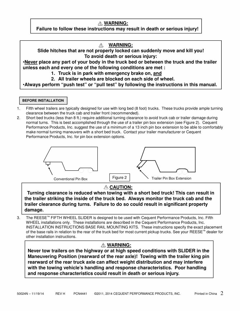
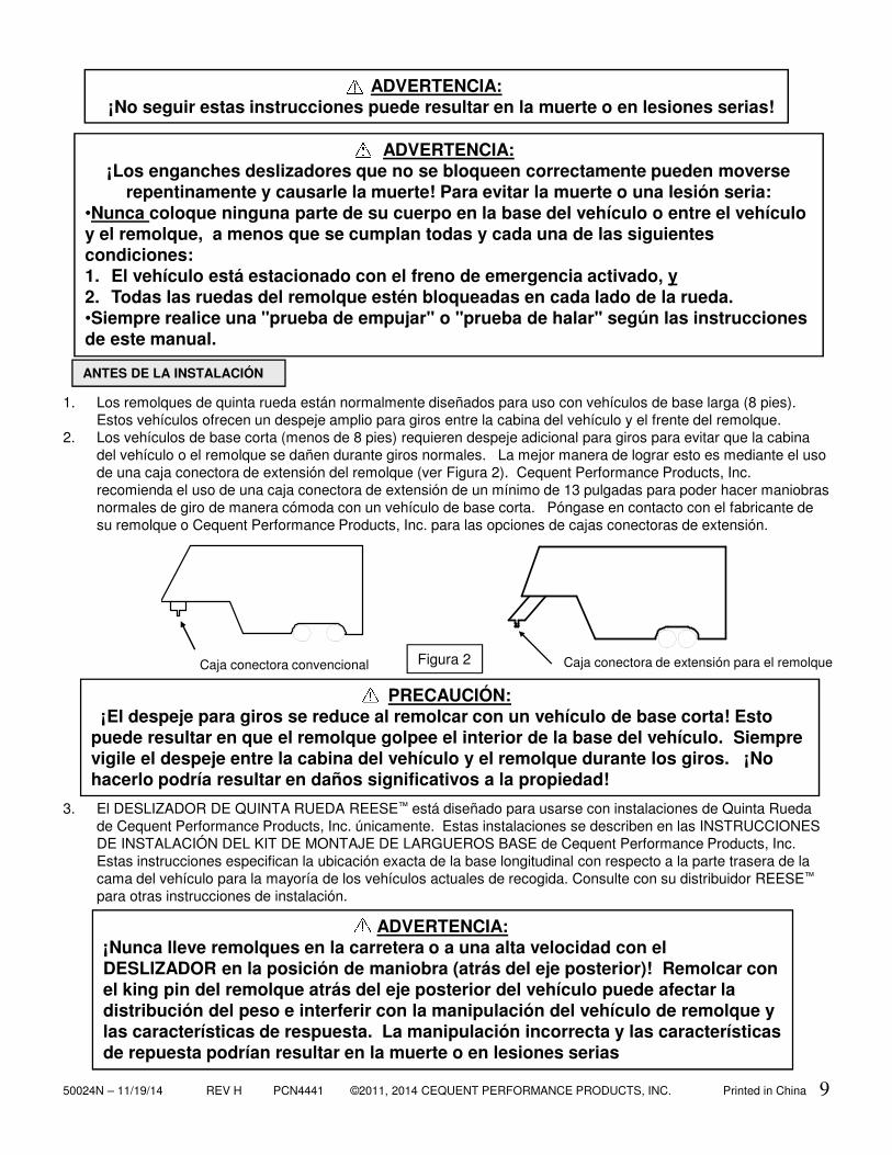
1. Fifth wheel trailers are typically designed for use with long bed (8 foot) trucks. These trucks provide ample turning clearance between the truck cab and trailer front (recommended).
2. Short bed trucks (less than 8 ft.) require additional turning clearance to avoid truck cab or trailer damage during normal turns. This is best accomplished through the use of a trailer pin box extension (see Figure 2). Cequent Performance Products, Inc. suggest the use of a minimum of a 13 inch pin box extension to be able to comfortably make normal turning maneuvers with a short bed truck. Contact your trailer manufacturer or Cequent Performance Products, Inc. for pin box extension options.
3. The REESE™ FIFTH WHEEL SLIDER is designed to be used with Cequent Performance Products, Inc. Fifth WHEEL installations only. These installations are described in the Cequent Performance Products, Inc. INSTALLATION INSTRUCTIONS BASE RAIL MOUNTING KITS. These instructions specify the exact placement of the base rails in relation to the rear of the truck bed for most current pickup trucks. See your REESE™ dealer for other installation instructions.
WARNING:Failure to follow these instructions may result in death or serious injury!
BEFORE INSTALLATION
Figure 2 Trailer Pin Box ExtensionConventional Pin Box
CAUTION:Turning clearance is reduced when towing with a short bed truck! This can result in
the trailer striking the inside of the truck bed. Always monitor the truck cab and the trailer clearance during turns. Failure to do so could result in significant property damage.
WARNING:Slide hitches that are not properly locked can suddenly move and kill you!
To avoid death or serious injury:•Never place any part of your body in the truck bed or between the truck and the trailer unless each and every one of the following conditions are met :
1. Truck is in park with emergency brake on, and2. All trailer wheels are blocked on each side of wheel.
•Always perform “push test” or “pull test” by following the instructions in this manual.
WARNING:Never tow trailers on the highway or at high speed conditions with SLIDER in the Maneuvering Position (rearward of the rear axle)! Towing with the trailer king pin rearward of the rear truck axle can affect weight distribution and may interfere with the towing vehicle’s handling and response characteristics. Poor handling and response characteristics could result in death or serious injury.
50024N – 11/19/14 REV H PCN4441 ©2011, 2014 CEQUENT PERFORMANCE PRODUCTS, INC. Printed in China 3
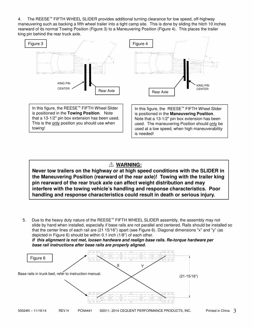
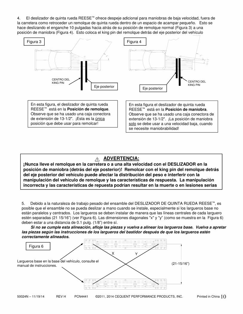
In this figure, the REESE™ FIFTH Wheel Slider is positioned in the Towing Position. Note that a 13-1/2" pin box extension has been used. This is the only position you should use when towing!
In this figure, the REESE™ FIFTH Wheel Slider is positioned in the Maneuvering Position. Note that a 13-1/2" pin box extension has been used. The maneuvering Position should only be used at a low speed, when high maneuverability is needed!
5. Due to the heavy duty nature of the REESE™ FIFTH WHEEL SLIDER assembly, the assembly may not slide by hand when installed, especially if base rails are not parallel and centered. Rails should be installed so that the center lines of each rail are (21 15/16”) apart (see Figure 6). Diagonal dimensions "x" and "y” (as depicted in Figure 6) should be within 0.1 inch (1/8”) of each other. If this alignment is not met, loosen hardware and realign base rails. Re-torque hardware per base rail instructions after base rails are properly aligned.
4. The REESE™ FIFTH WHEEL SLIDER provides additional turning clearance for low speed, off-highway maneuvering such as backing a fifth wheel trailer into a tight camp site. This is done by sliding the hitch 10 inches rearward of its normal Towing Position (Figure 3) to a Maneuvering Position (Figure 4). This places the trailer king pin behind the rear truck axle.
WARNING:Never tow trailers on the highway or at high speed conditions with the SLIDER in the Maneuvering Position (rearward of the rear axle)! Towing with the trailer king pin rearward of the rear truck axle can affect weight distribution and may interfere with the towing vehicle’s handling and response characteristics. Poor handling and response characteristics could result in death or serious injury.
Figure 6
Base rails in truck bed, refer to instruction manual.
X Y
Figure 3
Rear Axle Rear Axle
Figure 4
KING PIN CENTER
KING PIN
CENTER
(21-15/16”)
50024N – 11/19/14 REV H PCN4441 ©2011, 2014 CEQUENT PERFORMANCE PRODUCTS, INC. Printed in China 4
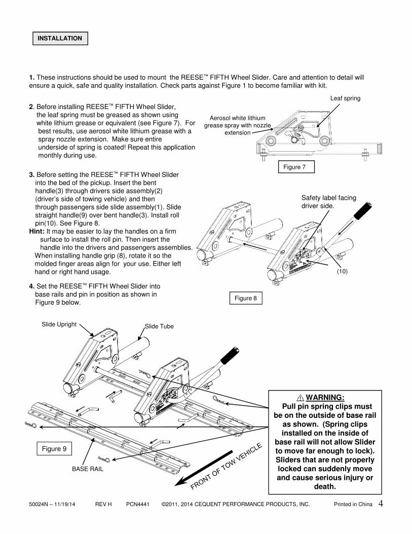
3. Before setting the REESE™ FIFTH Wheel Slider into the bed of the pickup. Insert the bent handle(3) through drivers side assembly(2) (driver’s side of towing vehicle) and then through passengers side slide assembly(1). Slide straight handle(9) over bent handle(3). Install roll pin(10). See Figure 8.
Hint: It may be easier to lay the handles on a firm surface to install the roll pin. Then insert the handle into the drivers and passengers assemblies.
When installing handle grip (8), rotate it so the molded finger areas align for your use. Either left hand or right hand usage.
4. Set the REESE™ FIFTH Wheel Slider into base rails and pin in position as shown in Figure 9 below.
Figure 9
Figure 8
2. Before installing REESE™ FIFTH Wheel Slider,the leaf spring must be greased as shown usingwhite lithium grease or equivalent (see Figure 7). For best results, use aerosol white lithium grease with a spray nozzle extension. Make sure entire underside of spring is coated! Repeat this application monthly during use.
Safety label facing driver side.
1. These instructions should be used to mount the REESE™ FIFTH Wheel Slider. Care and attention to detail will ensure a quick, safe and quality installation. Check parts against Figure 1 to become familiar with kit.
INSTALLATION
WARNING:Pull pin spring clips must
be on the outside of base rail as shown. (Spring clips installed on the inside of
base rail will not allow Slider to move far enough to lock). Sliders that are not properly locked can suddenly move and cause serious injury or
death.
Slide TubeSlide Upright
Aerosol white lithium grease spray with nozzle
extension
Leaf spring
Figure 7
BASE RAIL
(10)
50024N – 11/19/14 REV H PCN4441 ©2011, 2014 CEQUENT PERFORMANCE PRODUCTS, INC. Printed in China 5
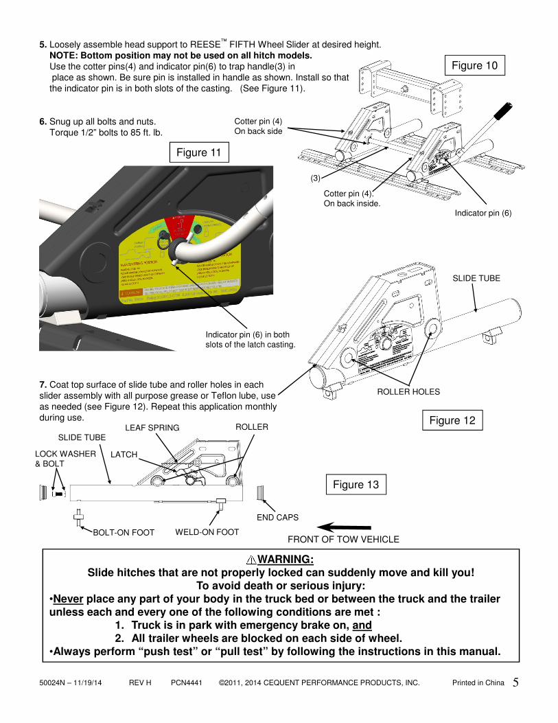
5. Loosely assemble head support to REESE™ FIFTH Wheel Slider at desired height. NOTE: Bottom position may not be used on all hitch models.Use the cotter pins(4) and indicator pin(6) to trap handle(3) in place as shown. Be sure pin is installed in handle as shown. Install so that the indicator pin is in both slots of the casting. (See Figure 11).
Figure 13
7. Coat top surface of slide tube and roller holes in each slider assembly with all purpose grease or Teflon lube, use as needed (see Figure 12). Repeat this application monthly during use. Figure 12
Figure 10
6. Snug up all bolts and nuts. Torque 1/2” bolts to 85 ft. lb.
Cotter pin (4).On back inside.
Indicator pin (6)
ROLLERSLIDE TUBE
LOCK WASHER & BOLT
END CAPS
LEAF SPRING
LATCH
WELD-ON FOOTBOLT-ON FOOT
Indicator pin (6) in both slots of the latch casting.
Figure 11
Cotter pin (4)On back side
ROLLER HOLES
SLIDE TUBE
WARNING:Slide hitches that are not properly locked can suddenly move and kill you!
To avoid death or serious injury:•Never place any part of your body in the truck bed or between the truck and the trailer unless each and every one of the following conditions are met :
1. Truck is in park with emergency brake on, and2. All trailer wheels are blocked on each side of wheel.
•Always perform “push test” or “pull test” by following the instructions in this manual.
(3)
FRONT OF TOW VEHICLE
50024N – 11/19/14 REV H PCN4441 ©2011, 2014 CEQUENT PERFORMANCE PRODUCTS, INC. Printed in China 6
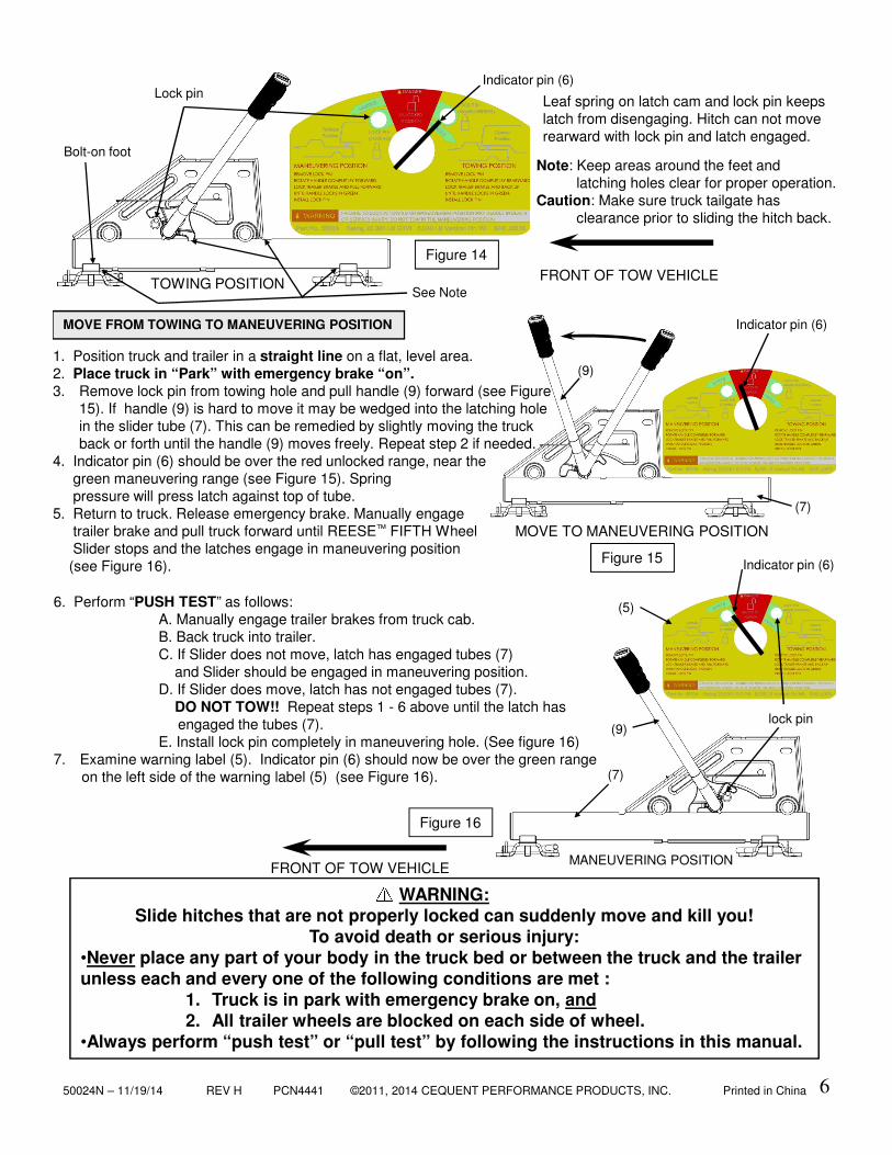
Leaf spring on latch cam and lock pin keeps latch from disengaging. Hitch can not move rearward with lock pin and latch engaged.
FRONT OF TOW VEHICLETOWING POSITION
Figure 14
1. Position truck and trailer in a straight line on a flat, level area.2. Place truck in “Park” with emergency brake “on”. 3. Remove lock pin from towing hole and pull handle (9) forward (see Figure
15). If handle (9) is hard to move it may be wedged into the latching hole in the slider tube (7). This can be remedied by slightly moving the truck back or forth until the handle (9) moves freely. Repeat step 2 if needed.
4. Indicator pin (6) should be over the red unlocked range, near thegreen maneuvering range (see Figure 15). Springpressure will press latch against top of tube.
5. Return to truck. Release emergency brake. Manually engagetrailer brake and pull truck forward until REESE™ FIFTH WheelSlider stops and the latches engage in maneuvering position (see Figure 16).
MOVE TO MANEUVERING POSITION
Figure 15
6. Perform “PUSH TEST” as follows:A. Manually engage trailer brakes from truck cab.B. Back truck into trailer.C. If Slider does not move, latch has engaged tubes (7)
and Slider should be engaged in maneuvering position.D. If Slider does move, latch has not engaged tubes (7).
DO NOT TOW!! Repeat steps 1 - 6 above until the latch has engaged the tubes (7).
E. Install lock pin completely in maneuvering hole. (See figure 16)7. Examine warning label (5). Indicator pin (6) should now be over the green range
on the left side of the warning label (5) (see Figure 16).
MOVE FROM TOWING TO MANEUVERING POSITION
MANEUVERING POSITION
Figure 16
Indicator pin (6)
Indicator pin (6)
Indicator pin (6)
FRONT OF TOW VEHICLE
WARNING:Slide hitches that are not properly locked can suddenly move and kill you!
To avoid death or serious injury:•Never place any part of your body in the truck bed or between the truck and the trailer unless each and every one of the following conditions are met :
1. Truck is in park with emergency brake on, and2. All trailer wheels are blocked on each side of wheel.
•Always perform “push test” or “pull test” by following the instructions in this manual.
Lock pin
Bolt-on foot
lock pin
(9)
(7)
(5)
(9)
(7)
See Note
Note: Keep areas around the feet and latching holes clear for proper operation.
Caution: Make sure truck tailgate has clearance prior to sliding the hitch back.
50024N – 11/19/14 REV H PCN4441 ©2011, 2014 CEQUENT PERFORMANCE PRODUCTS, INC. Printed in China7
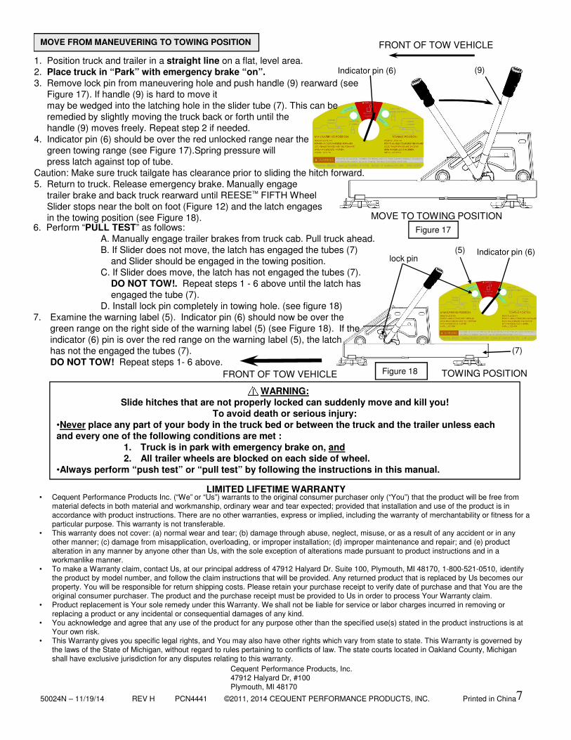
MOVE FROM MANEUVERING TO TOWING POSITION
1. Position truck and trailer in a straight line on a flat, level area.2. Place truck in “Park” with emergency brake “on”.3. Remove lock pin from maneuvering hole and push handle (9) rearward (see
Figure 17). If handle (9) is hard to move it may be wedged into the latching hole in the slider tube (7). This can be remedied by slightly moving the truck back or forth until the handle (9) moves freely. Repeat step 2 if needed.
4. Indicator pin (6) should be over the red unlocked range near thegreen towing range (see Figure 17).Spring pressure will press latch against top of tube.
Caution: Make sure truck tailgate has clearance prior to sliding the hitch forward.5. Return to truck. Release emergency brake. Manually engage
trailer brake and back truck rearward until REESE™ FIFTH WheelSlider stops near the bolt on foot (Figure 12) and the latch engagesin the towing position (see Figure 18).
6. Perform “PULL TEST” as follows:A. Manually engage trailer brakes from truck cab. Pull truck ahead.B. If Slider does not move, the latch has engaged the tubes (7)
and Slider should be engaged in the towing position.C. If Slider does move, the latch has not engaged the tubes (7).
DO NOT TOW!. Repeat steps 1 - 6 above until the latch has engaged the tube (7).
D. Install lock pin completely in towing hole. (see figure 18)7. Examine the warning label (5). Indicator pin (6) should now be over the
green range on the right side of the warning label (5) (see Figure 18). If the indicator (6) pin is over the red range on the warning label (5), the latch has not the engaged the tubes (7). DO NOT TOW! Repeat steps 1- 6 above.
MOVE TO TOWING POSITION
FRONT OF TOW VEHICLE
Figure 17
TOWING POSITION
Indicator pin (6)
Figure 18
Indicator pin (6)
• Cequent Performance Products Inc. (“We” or “Us”) warrants to the original consumer purchaser only (“You”) that the product will be free from material defects in both material and workmanship, ordinary wear and tear expected; provided that installation and use of the product is in accordance with product instructions. There are no other warranties, express or implied, including the warranty of merchantability or fitness for a particular purpose. This warranty is not transferable.
• This warranty does not cover: (a) normal wear and tear; (b) damage through abuse, neglect, misuse, or as a result of any accident or in any other manner; (c) damage from misapplication, overloading, or improper installation; (d) improper maintenance and repair; and (e) product alteration in any manner by anyone other than Us, with the sole exception of alterations made pursuant to product instructions and in a workmanlike manner.
• To make a Warranty claim, contact Us, at our principal address of 47912 Halyard Dr. Suite 100, Plymouth, MI 48170, 1-800-521-0510, identify the product by model number, and follow the claim instructions that will be provided. Any returned product that is replaced by Us becomes our property. You will be responsible for return shipping costs. Please retain your purchase receipt to verify date of purchase and that You are the original consumer purchaser. The product and the purchase receipt must be provided to Us in order to process Your Warranty claim.
• Product replacement is Your sole remedy under this Warranty. We shall not be liable for service or labor charges incurred in removing or replacing a product or any incidental or consequential damages of any kind.
• You acknowledge and agree that any use of the product for any purpose other than the specified use(s) stated in the product instructions is at Your own risk.
• This Warranty gives you specific legal rights, and You may also have other rights which vary from state to state. This Warranty is governed by the laws of the State of Michigan, without regard to rules pertaining to conflicts of law. The state courts located in Oakland County, Michigan shall have exclusive jurisdiction for any disputes relating to this warranty.
LIMITED LIFETIME WARRANTY
Cequent Performance Products, Inc.47912 Halyard Dr, #100Plymouth, MI 48170
FRONT OF TOW VEHICLE
WARNING:Slide hitches that are not properly locked can suddenly move and kill you!
To avoid death or serious injury:•Never place any part of your body in the truck bed or between the truck and the trailer unless each and every one of the following conditions are met :
1. Truck is in park with emergency brake on, and2. All trailer wheels are blocked on each side of wheel.
•Always perform “push test” or “pull test” by following the instructions in this manual.
lock pin
(9)
(5)
(7)
50024N – 11/19/14 REV H PCN4441 ©2011, 2014 CEQUENT PERFORMANCE PRODUCTS, INC. Printed in China
Plymouth, MI.
(REVERSO)
Figura 1
(3) Manija
(1) Entregue este manual al usuario final.(2) Demuestre físicamente los procedimientos en este manual al usuario final.(3) Pida al usuario final que le demuestre que entiende los procedimientos.
(1) Lea y siga este manual todas las veces que use este deslizador de quinta rueda de REESE™
(2) Guarde este Manual para referencia futura.(3) Distribuya copias de este manual a cualquier otro usuario o propietario del deslizador de quinta rueda de REESE™
(4) Nunca retire las calcomanías de advertencia del deslizador de quinta rueda que se muestran en la portada de este manual. En caso de daños contacte a CequentPerformance Products, Inc. (1-888-521-0510) para adhesivos de reemplazo gratuitos.
CONCESIONARIO/INSTALADOR:
USUARIO FINAL:
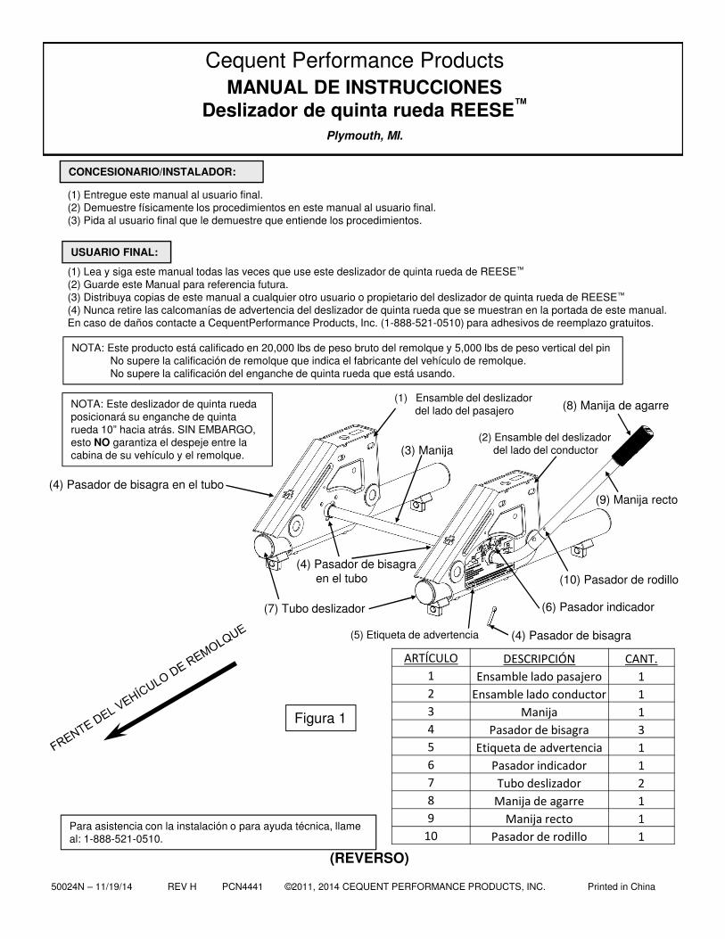
MANUAL DE INSTRUCCIONESDeslizador de quinta rueda REESE™
(1) Ensamble del deslizadordel lado del pasajero
(5) Etiqueta de advertencia
(2) Ensamble del deslizadordel lado del conductor
(6) Pasador indicador
Cequent Performance Products
(7) Tubo deslizador
(4) Pasador de bisagra en el tubo
NOTA: Este producto está calificado en 20,000 lbs de peso bruto del remolque y 5,000 lbs de peso vertical del pin No supere la calificación de remolque que indica el fabricante del vehículo de remolque.No supere la calificación del enganche de quinta rueda que está usando.
Para asistencia con la instalación o para ayuda técnica, llame al: 1-888-521-0510.
NOTA: Este deslizador de quinta rueda posicionará su enganche de quinta rueda 10” hacia atrás. SIN EMBARGO, esto NO garantiza el despeje entre la cabina de su vehículo y el remolque.
(4) Pasador de bisagra
ARTÍCULO DESCRIPCIÓN CANT.
1 Ensamble lado pasajero 1
2 Ensamble lado conductor 1
3 Manija 1
4 Pasador de bisagra 3
5 Etiqueta de advertencia 1
6 Pasador indicador 1
7 Tubo deslizador 2
8 Manija de agarre 1
9 Manija recto 1
10 Pasador de rodillo 1
(8) Manija de agarre
(4) Pasador de bisagra en el tubo
(10) Pasador de rodillo
(9) Manija recto
50024N – 11/19/14 REV H PCN4441 ©2011, 2014 CEQUENT PERFORMANCE PRODUCTS, INC. Printed in China 9
1. Los remolques de quinta rueda están normalmente diseñados para uso con vehículos de base larga (8 pies). Estos vehículos ofrecen un despeje amplio para giros entre la cabina del vehículo y el frente del remolque.
2. Los vehículos de base corta (menos de 8 pies) requieren despeje adicional para giros para evitar que la cabina del vehículo o el remolque se dañen durante giros normales. La mejor manera de lograr esto es mediante el uso de una caja conectora de extensión del remolque (ver Figura 2). Cequent Performance Products, Inc. recomienda el uso de una caja conectora de extensión de un mínimo de 13 pulgadas para poder hacer maniobras normales de giro de manera cómoda con un vehículo de base corta. Póngase en contacto con el fabricante de su remolque o Cequent Performance Products, Inc. para las opciones de cajas conectoras de extensión.
3. El DESLIZADOR DE QUINTA RUEDA REESE™ está diseñado para usarse con instalaciones de Quinta Rueda de Cequent Performance Products, Inc. únicamente. Estas instalaciones se describen en las INSTRUCCIONES DE INSTALACIÓN DEL KIT DE MONTAJE DE LARGUEROS BASE de Cequent Performance Products, Inc. Estas instrucciones especifican la ubicación exacta de la base longitudinal con respecto a la parte trasera de la cama del vehículo para la mayoría de los vehículos actuales de recogida. Consulte con su distribuidor REESE™
para otras instrucciones de instalación.
ADVERTENCIA:¡No seguir estas instrucciones puede resultar en la muerte o en lesiones serias!
ANTES DE LA INSTALACIÓN
Figura 2 Caja conectora de extensión para el remolque Caja conectora convencional
PRECAUCIÓN:¡El despeje para giros se reduce al remolcar con un vehículo de base corta! Esto
puede resultar en que el remolque golpee el interior de la base del vehículo. Siempre vigile el despeje entre la cabina del vehículo y el remolque durante los giros. ¡No hacerlo podría resultar en daños significativos a la propiedad!
ADVERTENCIA:¡Los enganches deslizadores que no se bloqueen correctamente pueden moverse
repentinamente y causarle la muerte! Para evitar la muerte o una lesión seria:•Nunca coloque ninguna parte de su cuerpo en la base del vehículo o entre el vehículo y el remolque, a menos que se cumplan todas y cada una de las siguientes condiciones:1. El vehículo está estacionado con el freno de emergencia activado, y2. Todas las ruedas del remolque estén bloqueadas en cada lado de la rueda.•Siempre realice una "prueba de empujar" o "prueba de halar" según las instrucciones de este manual.
ADVERTENCIA:¡Nunca lleve remolques en la carretera o a una alta velocidad con el DESLIZADOR en la posición de maniobra (atrás del eje posterior)! Remolcar con el king pin del remolque atrás del eje posterior del vehículo puede afectar la distribución del peso e interferir con la manipulación del vehículo de remolque y las características de respuesta. La manipulación incorrecta y las características de repuesta podrían resultar en la muerte o en lesiones serias
50024N – 11/19/14 REV H PCN4441 ©2011, 2014 CEQUENT PERFORMANCE PRODUCTS, INC. Printed in China 10
En esta figura, el deslizador de quinta ruedaREESE™ está en la Posición de remolque. Observe que se ha usado una caja conectorade extensión de 13-1/2". ¡Esta es la únicaposición que debe usar para remolcar!
En esta figura el deslizador de quinta ruedaREESE™ está en la Posición de maniobra. Observe que se ha usado una caja conectora de extensión de 13-1/2". ¡La posición de maniobrasolo se debe usar a una velocidad baja, cuandose necesite maniobrabilidad!
5. Debido a la naturaleza de trabajo pesado del ensamble del DESLIZADOR DE QUINTA RUEDA REESE™, es posible que el ensamble no se pueda deslizar a mano cuando se instale, especialmente si los largueros base no están paralelos y centrados. Los largueros se deben instalar de manera que las líneas centrales de cada larguero estén separadas (21 15/16”) (ver Figura 6). Las dimensiones diagonales "x" y "y” (como se muestra en la Figura 6) deben estar a una distancia de 0.1 pulg. (1/8”) entre sí.
Si no se cumple esta alineación, afloje las piezas y vuelva a alinear los largueros base. Vuelva a apretar las piezas según las instrucciones de los largueros del bastidor después de que los largueros estén correctamente alineados.
4. El deslizador de quinta rueda REESE™ ofrece despeje adicional para maniobras de baja velocidad, fuera de la carretera como retroceder un remolque de quinta rueda dentro de un espacio de acampar pequeño. Esto se hace deslizando el enganche 10 pulgadas hacia atrás de su posición de remolque normal (Figura 3) a una posición de maniobra (Figura 4). Esto coloca el king pin del remolque detrás del eje posterior del vehículo
ADVERTENCIA:¡Nunca lleve el remolque en la carretera o a una alta velocidad con el DESLIZADOR en la posición de maniobra (detrás del eje posterior)! Remolcar con el king pin del remolque detrás del eje posterior del vehículo puede afectar la distribución del peso e interferir con la manipulación del vehículo de remolque y las características de respuesta. La manipulación incorrecta y las características de repuesta podrían resultar en la muerte o en lesiones serias
Figura 6
Largueros base en la base del vehículo, consulte el manual de instrucciones.
X Y
Figura 3
Eje posterior Eje posterior
Figura 4
CENTRO DEL KING PIN
CENTRO DEL KING PIN
(21-15/16”)
50024N – 11/19/14 REV H PCN4441 ©2011, 2014 CEQUENT PERFORMANCE PRODUCTS, INC. Printed in China 11
Etiqueta de seguridad orientada hacia el lado del conductor.
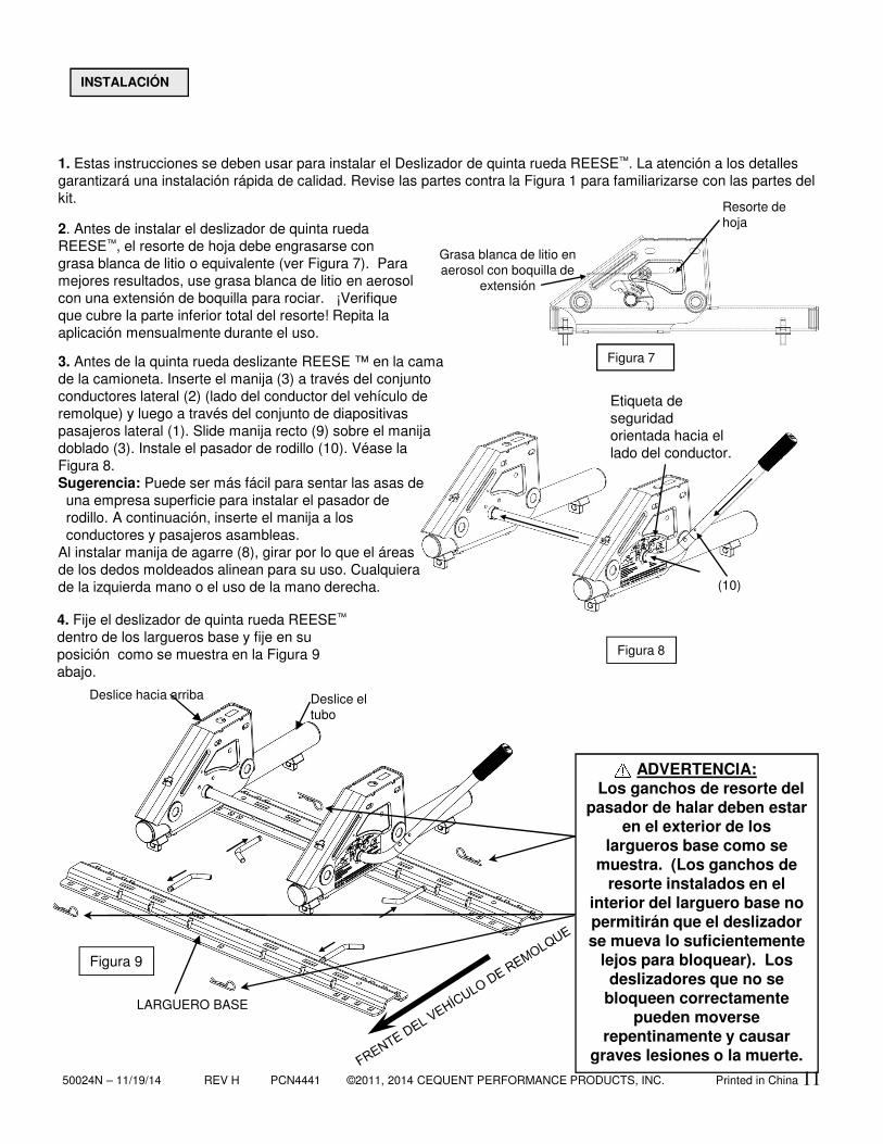
3. Antes de la quinta rueda deslizante REESE ™ en la cama de la camioneta. Inserte el manija (3) a través del conjunto conductores lateral (2) (lado del conductor del vehículo de remolque) y luego a través del conjunto de diapositivas pasajeros lateral (1). Slide manija recto (9) sobre el manija doblado (3). Instale el pasador de rodillo (10). Véase la Figura 8.Sugerencia: Puede ser más fácil para sentar las asas de una empresa superficie para instalar el pasador de rodillo. A continuación, inserte el manija a los conductores y pasajeros asambleas.
Al instalar manija de agarre (8), girar por lo que el áreas de los dedos moldeados alinean para su uso. Cualquiera de la izquierda mano o el uso de la mano derecha.
4. Fije el deslizador de quinta rueda REESE™
dentro de los largueros base y fije en suposición como se muestra en la Figura 9 abajo.
Figura 9
Figura 8
2. Antes de instalar el deslizador de quinta rueda REESE™, el resorte de hoja debe engrasarse con grasa blanca de litio o equivalente (ver Figura 7). Para mejores resultados, use grasa blanca de litio en aerosol con una extensión de boquilla para rociar. ¡Verifique que cubre la parte inferior total del resorte! Repita la aplicación mensualmente durante el uso.
1. Estas instrucciones se deben usar para instalar el Deslizador de quinta rueda REESE™. La atención a los detallesgarantizará una instalación rápida de calidad. Revise las partes contra la Figura 1 para familiarizarse con las partes del kit.
INSTALACIÓN
ADVERTENCIA:Los ganchos de resorte del
pasador de halar deben estar en el exterior de los
largueros base como se muestra. (Los ganchos de
resorte instalados en el interior del larguero base no permitirán que el deslizador se mueva lo suficientemente
lejos para bloquear). Los deslizadores que no se
bloqueen correctamente pueden moverse
repentinamente y causar graves lesiones o la muerte.
Deslice el tubo
Deslice hacia arriba
Grasa blanca de litio en aerosol con boquilla de
extensión
Resorte de hoja
Figura 7
LARGUERO BASE
(10)
50024N – 11/19/14 REV H PCN4441 ©2011, 2014 CEQUENT PERFORMANCE PRODUCTS, INC. Printed in China 12
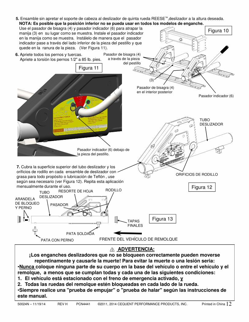
5. Ensamble sin apretar el soporte de cabeza al deslizador de quinta rueda REESE™,deslizador a la altura deseada. NOTA: Es posible que la posición inferior no se pueda usar en todos los modelos de enganche. Use el pasador de bisagra (4) y pasador indicador (6) para atrapar lamanija (3) en su lugar como se muestra. Instale el pasador indicador en la manija como se muestra. Instálelo de manera que el pasador indicador pase a través del lado inferior de la pieza del pestillo y que quede en la ranura de la pieza. (Ver Figura 11).
Figura 13
7. Cubra la superficie superior del tubo deslizador y los orificios de rodillo en cada ensamble de deslizador con grasa para todo propósito o lubricación de Teflón , use según sea necesario (ver Figura 12). Repita esta aplicación mensualmente durante el uso. Figura 12
Figura 10
6. Apriete todos los pernos y tuercas. Apriete a torsión los pernos 1/2" a 85 lb. pies.
Pasador de bisagra (4)en el interior posterior
Pasador indicador (6)
RODILLOTUBO DESLIZADOR
ARANDELA DE BLOQUEO Y PERNO
TAPAS FINALES
RESORTE DE HOJA
PASADOR
PATA SOLDADA
PATA CON PERNO
Pasador indicador (6) debajo de la pieza del pestillo.
Figura 11
Pasador de bisagra (4)a través de la pieza
del pestillo
ORIFICIOS DE RODILLO
TUBO DESLIZADOR
ADVERTENCIA:¡Los enganches deslizadores que no se bloqueen correctamente pueden moverse
repentinamente y causarle la muerte! Para evitar la muerte o una lesión seria:•Nunca coloque ninguna parte de su cuerpo en la base del vehículo o entre el vehículo y el remolque, a menos que se cumplan todas y cada una de las siguientes condiciones:1. El vehículo está estacionado con el freno de emergencia activado, y2. Todas las ruedas del remolque estén bloqueadas en cada lado de la rueda.•Siempre realice una "prueba de empujar" o "prueba de halar" según las instrucciones de este manual.
(3)
FRENTE DEL VEHÍCULO DE REMOLQUE
50024N – 11/19/14 REV H PCN4441 ©2011, 2014 CEQUENT PERFORMANCE PRODUCTS, INC. Printed in China
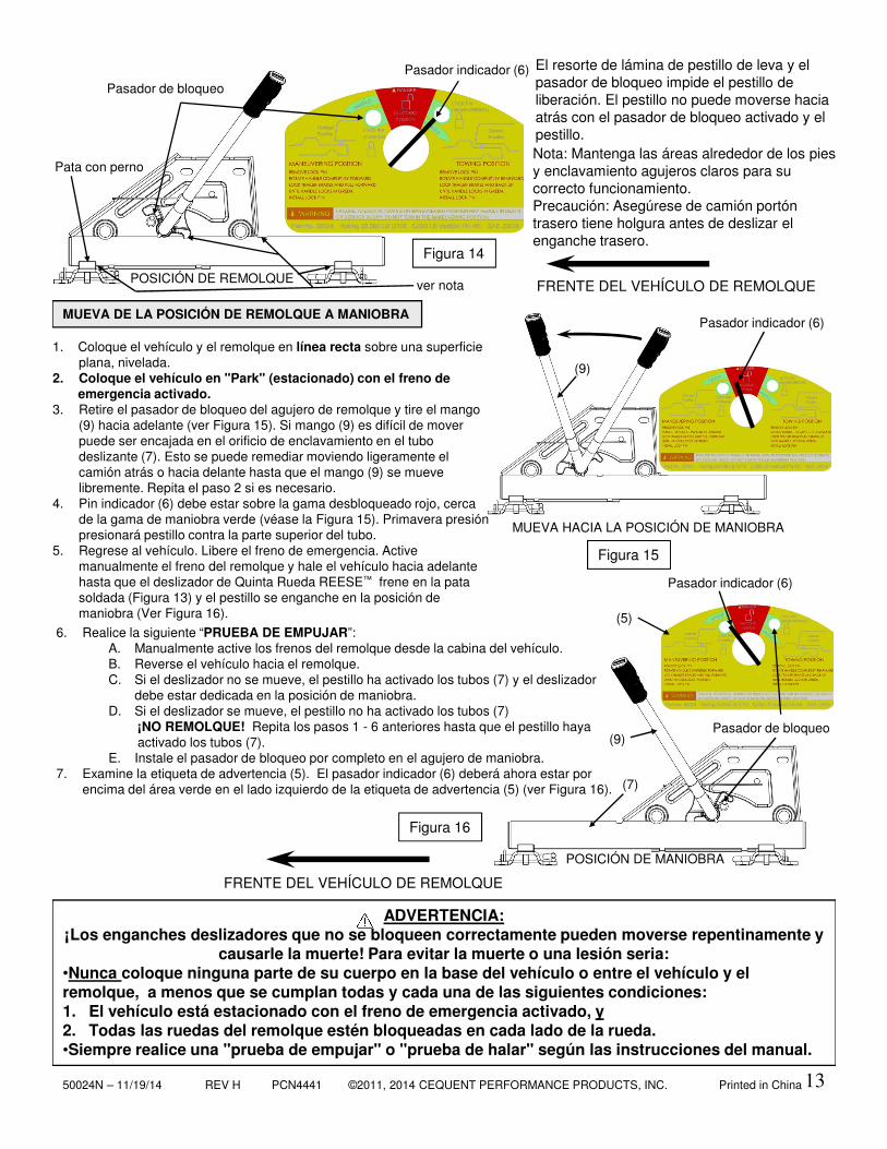
6. Realice la siguiente “PRUEBA DE EMPUJAR”:A. Manualmente active los frenos del remolque desde la cabina del vehículo. B. Reverse el vehículo hacia el remolque. C. Si el deslizador no se mueve, el pestillo ha activado los tubos (7) y el deslizador
debe estar dedicada en la posición de maniobra.D. Si el deslizador se mueve, el pestillo no ha activado los tubos (7)
¡NO REMOLQUE! Repita los pasos 1 - 6 anteriores hasta que el pestillo haya activado los tubos (7).
E. Instale el pasador de bloqueo por completo en el agujero de maniobra.7. Examine la etiqueta de advertencia (5). El pasador indicador (6) deberá ahora estar por
encima del área verde en el lado izquierdo de la etiqueta de advertencia (5) (ver Figura 16).
Pasador de bloqueo
(5)
(9)
(7)
(9)
13
El resorte de lámina de pestillo de leva y el pasador de bloqueo impide el pestillo de liberación. El pestillo no puede moverse hacia atrás con el pasador de bloqueo activado y el pestillo.
FRENTE DEL VEHÍCULO DE REMOLQUEPOSICIÓN DE REMOLQUE
Figura 14
1. Coloque el vehículo y el remolque en línea recta sobre una superficie plana, nivelada.
2. Coloque el vehículo en "Park" (estacionado) con el freno de emergencia activado.
3. Retire el pasador de bloqueo del agujero de remolque y tire el mango (9) hacia adelante (ver Figura 15). Si mango (9) es difícil de mover puede ser encajada en el orificio de enclavamiento en el tubo deslizante (7). Esto se puede remediar moviendo ligeramente el camión atrás o hacia delante hasta que el mango (9) se mueve libremente. Repita el paso 2 si es necesario.
4. Pin indicador (6) debe estar sobre la gama desbloqueado rojo, cerca de la gama de maniobra verde (véase la Figura 15). Primavera presión presionará pestillo contra la parte superior del tubo.
5. Regrese al vehículo. Libere el freno de emergencia. Active manualmente el freno del remolque y hale el vehículo hacia adelante hasta que el deslizador de Quinta Rueda REESE™ frene en la pata soldada (Figura 13) y el pestillo se enganche en la posición de maniobra (Ver Figura 16).
MUEVA HACIA LA POSICIÓN DE MANIOBRA
Figura 15
MUEVA DE LA POSICIÓN DE REMOLQUE A MANIOBRA
POSICIÓN DE MANIOBRA
Figura 16
Pasador indicador (6)
Pasador indicador (6)
Pasador indicador (6)
FRENTE DEL VEHÍCULO DE REMOLQUE
ADVERTENCIA:¡Los enganches deslizadores que no se bloqueen correctamente pueden moverse repentinamente y
causarle la muerte! Para evitar la muerte o una lesión seria:•Nunca coloque ninguna parte de su cuerpo en la base del vehículo o entre el vehículo y el remolque, a menos que se cumplan todas y cada una de las siguientes condiciones:1. El vehículo está estacionado con el freno de emergencia activado, y2. Todas las ruedas del remolque estén bloqueadas en cada lado de la rueda.•Siempre realice una "prueba de empujar" o "prueba de halar" según las instrucciones del manual.
Pata con perno
Pasador de bloqueo
Nota: Mantenga las áreas alrededor de los pies y enclavamiento agujeros claros para su correcto funcionamiento.Precaución: Asegúrese de camión portón trasero tiene holgura antes de deslizar el enganche trasero.
ver nota
50024N – 11/19/14 REV H PCN4441 ©2011, 2014 CEQUENT PERFORMANCE PRODUCTS, INC. Printed in China
Pasador de bloqueo (5)
(7)
(9)
14
MUEVA DE LA POSICIÓN DE MANIOBRA A POSICIÓN DE REMOLQUE
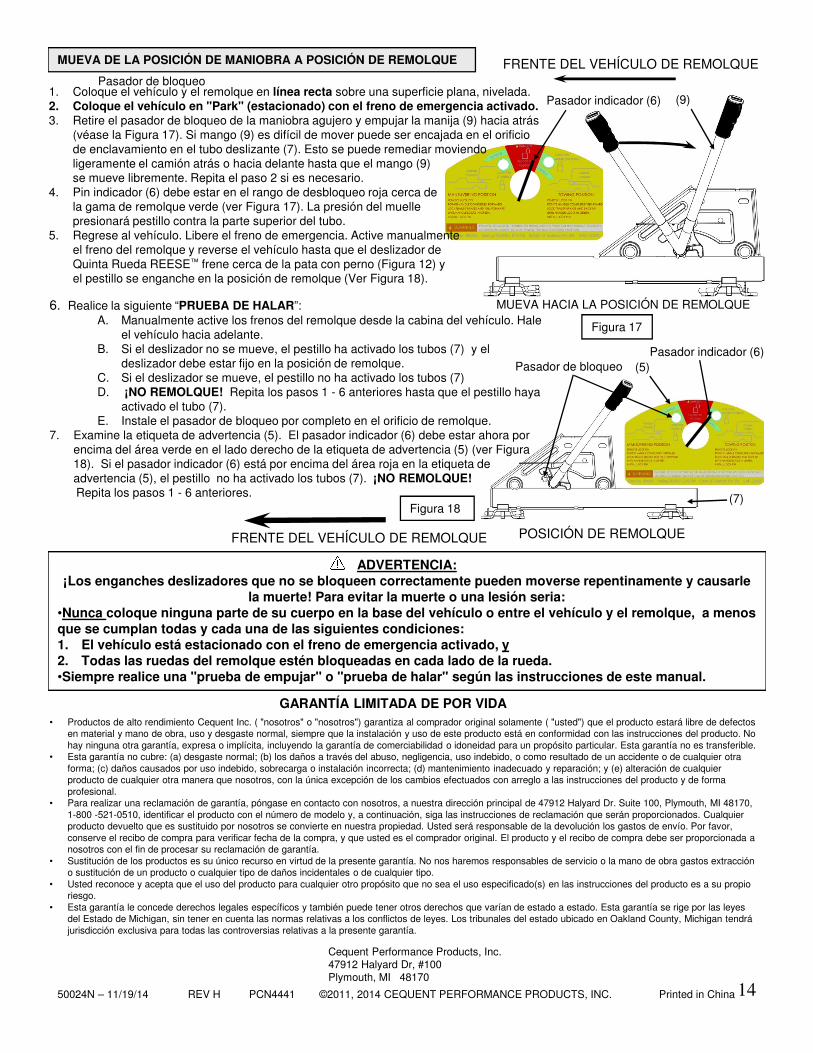
1. Coloque el vehículo y el remolque en línea recta sobre una superficie plana, nivelada.2. Coloque el vehículo en "Park" (estacionado) con el freno de emergencia activado.3. Retire el pasador de bloqueo de la maniobra agujero y empujar la manija (9) hacia atrás
(véase la Figura 17). Si mango (9) es difícil de mover puede ser encajada en el orificio de enclavamiento en el tubo deslizante (7). Esto se puede remediar moviendo ligeramente el camión atrás o hacia delante hasta que el mango (9) se mueve libremente. Repita el paso 2 si es necesario.
4. Pin indicador (6) debe estar en el rango de desbloqueo roja cerca de la gama de remolque verde (ver Figura 17). La presión del muelle presionará pestillo contra la parte superior del tubo.
5. Regrese al vehículo. Libere el freno de emergencia. Active manualmente el freno del remolque y reverse el vehículo hasta que el deslizador de Quinta Rueda REESE™ frene cerca de la pata con perno (Figura 12) y el pestillo se enganche en la posición de remolque (Ver Figura 18).
6. Realice la siguiente “PRUEBA DE HALAR”:A. Manualmente active los frenos del remolque desde la cabina del vehículo. Hale
el vehículo hacia adelante.B. Si el deslizador no se mueve, el pestillo ha activado los tubos (7) y el
deslizador debe estar fijo en la posición de remolque.C. Si el deslizador se mueve, el pestillo no ha activado los tubos (7)D. ¡NO REMOLQUE! Repita los pasos 1 - 6 anteriores hasta que el pestillo haya
activado el tubo (7).E. Instale el pasador de bloqueo por completo en el orificio de remolque.
7. Examine la etiqueta de advertencia (5). El pasador indicador (6) debe estar ahora por encima del área verde en el lado derecho de la etiqueta de advertencia (5) (ver Figura 18). Si el pasador indicador (6) está por encima del área roja en la etiqueta de advertencia (5), el pestillo no ha activado los tubos (7). ¡NO REMOLQUE!Repita los pasos 1 - 6 anteriores.
MUEVA HACIA LA POSICIÓN DE REMOLQUE
FRENTE DEL VEHÍCULO DE REMOLQUE
Figura 17
POSICIÓN DE REMOLQUE
Pasador indicador (6)
Figura 18
Pasador indicador (6)
• Productos de alto rendimiento Cequent Inc. ( "nosotros" o "nosotros") garantiza al comprador original solamente ( "usted") que el producto estará libre de defectosen material y mano de obra, uso y desgaste normal, siempre que la instalación y uso de este producto está en conformidad con las instrucciones del producto. No hay ninguna otra garantía, expresa o implícita, incluyendo la garantía de comerciabilidad o idoneidad para un propósito particular. Esta garantía no es transferible.
• Esta garantía no cubre: (a) desgaste normal; (b) los daños a través del abuso, negligencia, uso indebido, o como resultado de un accidente o de cualquier otraforma; (c) daños causados por uso indebido, sobrecarga o instalación incorrecta; (d) mantenimiento inadecuado y reparación; y (e) alteración de cualquierproducto de cualquier otra manera que nosotros, con la única excepción de los cambios efectuados con arreglo a las instrucciones del producto y de forma profesional.
• Para realizar una reclamación de garantía, póngase en contacto con nosotros, a nuestra dirección principal de 47912 Halyard Dr. Suite 100, Plymouth, MI 48170, 1-800 -521-0510, identificar el producto con el número de modelo y, a continuación, siga las instrucciones de reclamación que serán proporcionados. Cualquierproducto devuelto que es sustituido por nosotros se convierte en nuestra propiedad. Usted será responsable de la devolución los gastos de envío. Por favor, conserve el recibo de compra para verificar fecha de la compra, y que usted es el comprador original. El producto y el recibo de compra debe ser proporcionada a nosotros con el fin de procesar su reclamación de garantía.
• Sustitución de los productos es su único recurso en virtud de la presente garantía. No nos haremos responsables de servicio o la mano de obra gastos extraccióno sustitución de un producto o cualquier tipo de daños incidentales o de cualquier tipo.
• Usted reconoce y acepta que el uso del producto para cualquier otro propósito que no sea el uso especificado(s) en las instrucciones del producto es a su propioriesgo.
• Esta garantía le concede derechos legales específicos y también puede tener otros derechos que varían de estado a estado. Esta garantía se rige por las leyesdel Estado de Michigan, sin tener en cuenta las normas relativas a los conflictos de leyes. Los tribunales del estado ubicado en Oakland County, Michigan tendrájurisdicción exclusiva para todas las controversias relativas a la presente garantía.
GARANTÍA LIMITADA DE POR VIDA
Cequent Performance Products, Inc.47912 Halyard Dr, #100Plymouth, MI 48170
FRENTE DEL VEHÍCULO DE REMOLQUE
ADVERTENCIA:¡Los enganches deslizadores que no se bloqueen correctamente pueden moverse repentinamente y causarle
la muerte! Para evitar la muerte o una lesión seria:•Nunca coloque ninguna parte de su cuerpo en la base del vehículo o entre el vehículo y el remolque, a menos que se cumplan todas y cada una de las siguientes condiciones:1. El vehículo está estacionado con el freno de emergencia activado, y2. Todas las ruedas del remolque estén bloqueadas en cada lado de la rueda.•Siempre realice una "prueba de empujar" o "prueba de halar" según las instrucciones de este manual.
Pasador de bloqueo
50024N – 11/19/14 REV H PCN4441 ©2011, 2014 CEQUENT PERFORMANCE PRODUCTS, INC. Printed in China
PLYMOUTH, MI
(VERSO)
Figure 1
(3) Poignée
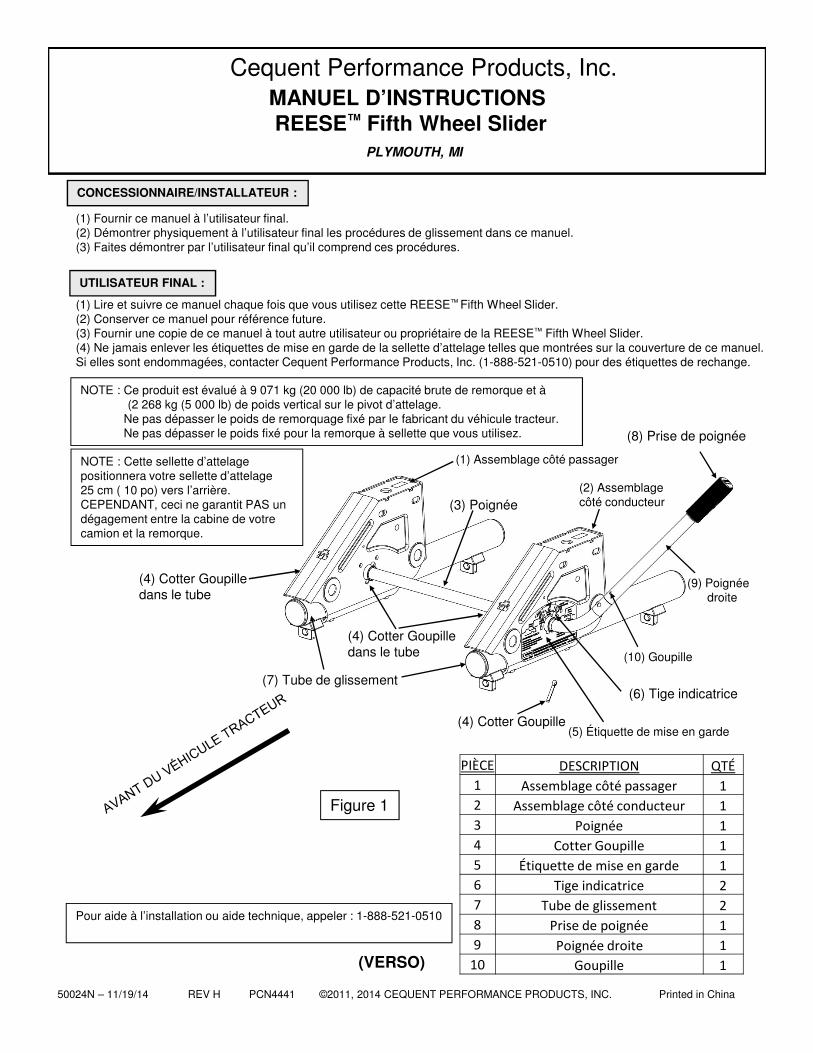
(1) Fournir ce manuel à l’utilisateur final.(2) Démontrer physiquement à l’utilisateur final les procédures de glissement dans ce manuel.(3) Faites démontrer par l’utilisateur final qu’il comprend ces procédures.
(1) Lire et suivre ce manuel chaque fois que vous utilisez cette REESE™ Fifth Wheel Slider.(2) Conserver ce manuel pour référence future.(3) Fournir une copie de ce manuel à tout autre utilisateur ou propriétaire de la REESE™ Fifth Wheel Slider.(4) Ne jamais enlever les étiquettes de mise en garde de la sellette d’attelage telles que montrées sur la couverture de ce manuel. Si elles sont endommagées, contacter Cequent Performance Products, Inc. (1-888-521-0510) pour des étiquettes de rechange.
CONCESSIONNAIRE/INSTALLATEUR :
UTILISATEUR FINAL :
MANUEL D’INSTRUCTIONSREESE™ Fifth Wheel Slider
(1) Assemblage côté passager
(5) Étiquette de mise en garde
(2) Assemblage côté conducteur
(6) Tige indicatrice
(4) Cotter Goupille dans le tube
Cequent Performance Products, Inc.
(7) Tube de glissement
NOTE : Ce produit est évalué à 9 071 kg (20 000 lb) de capacité brute de remorque et à (2 268 kg (5 000 lb) de poids vertical sur le pivot d’attelage.
Ne pas dépasser le poids de remorquage fixé par le fabricant du véhicule tracteur.Ne pas dépasser le poids fixé pour la remorque à sellette que vous utilisez.
Pour aide à l’installation ou aide technique, appeler : 1-888-521-0510
NOTE : Cette sellette d’attelage positionnera votre sellette d’attelage 25 cm ( 10 po) vers l’arrière. CEPENDANT, ceci ne garantit PAS un dégagement entre la cabine de votre camion et la remorque.
(4) Cotter Goupille
PIÈCE DESCRIPTION QTÉ
1 Assemblage côté passager 1
2 Assemblage côté conducteur 1
3 Poignée 1
4 Cotter Goupille 1
5 Étiquette de mise en garde 1
6 Tige indicatrice 2
7 Tube de glissement 2
8 Prise de poignée 1
9 Poignée droite 1
10 Goupille 1
(8) Prise de poignée
(4) Cotter Goupille dans le tube
(10) Goupille
(9) Poignée droite
50024N – 11/19/14 REV H PCN4441 ©2011, 2014 CEQUENT PERFORMANCE PRODUCTS, INC. Printed in China 16
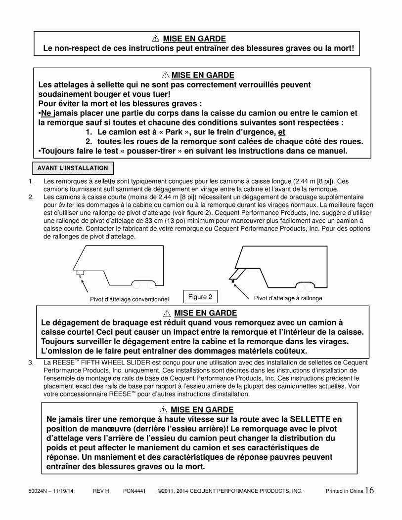
1. Les remorques à sellette sont typiquement conçues pour les camions à caisse longue (2,44 m [8 pi]). Ces camions fournissent suffisamment de dégagement en virage entre la cabine et l’avant de la remorque.
2. Les camions à caisse courte (moins de 2,44 m [8 pi]) nécessitent un dégagement de braquage supplémentaire pour éviter les dommages à la cabine du camion ou à la remorque durant les virages normaux. La meilleure façon est d’utiliser une rallonge de pivot d’attelage (voir figure 2). Cequent Performance Products, Inc. suggère d’utiliser une rallonge de pivot d’attelage de 33 cm (13 po) minimum pour manœuvrer plus facilement avec un camion à caisse courte. Contacter le fabricant de votre remorque ou Cequent Performance Products, Inc. Pour des options de rallonges de pivot d’attelage.
3. La REESE™ FIFTH WHEEL SLIDER est conçu pour une utilisation avec des installation de sellettes de Cequent Performance Products, Inc. uniquement. Ces installations sont décrites dans les instructions d’installation de l’ensemble de montage de rails de base de Cequent Performance Products, Inc. Ces instructions précisent le placement exact des rails de base par rapport à l’essieu arrière de la plupart des camionnettes actuelles. Voir votre concessionnaire REESE™ pour d’autres instructions d’installation.
MISE EN GARDELe non-respect de ces instructions peut entraîner des blessures graves ou la mort!
AVANT L’INSTALLATION
Figure 2 Pivot d’attelage à rallongePivot d’attelage conventionnel
MISE EN GARDELe dégagement de braquage est réduit quand vous remorquez avec un camion à caisse courte! Ceci peut causer un impact entre la remorque et l’intérieur de la caisse. Toujours surveiller le dégagement entre la cabine et la remorque dans les virages. L’omission de le faire peut entraîner des dommages matériels coûteux.
MISE EN GARDELes attelages à sellette qui ne sont pas correctement verrouillés peuvent soudainement bouger et vous tuer!Pour éviter la mort et les blessures graves :•Ne jamais placer une partie du corps dans la caisse du camion ou entre le camion et la remorque sauf si toutes et chacune des conditions suivantes sont respectées :
1. Le camion est à « Park », sur le frein d’urgence, et2. toutes les roues de la remorque sont calées de chaque côté des roues.
•Toujours faire le test « pousser-tirer » en suivant les instructions dans ce manuel.
MISE EN GARDENe jamais tirer une remorque à haute vitesse sur la route avec la SELLETTE en position de manœuvre (derrière l’essieu arrière)! Le remorquage avec le pivot d’attelage vers l’arrière de l’essieu du camion peut changer la distribution du poids et peut affecter le maniement du camion et ses caractéristiques de réponse. Un maniement et des caractéristiques de réponse pauvres peuvent entraîner des blessures graves ou la mort.
50024N – 11/19/14 REV H PCN4441 ©2011, 2014 CEQUENT PERFORMANCE PRODUCTS, INC. Printed in China 17
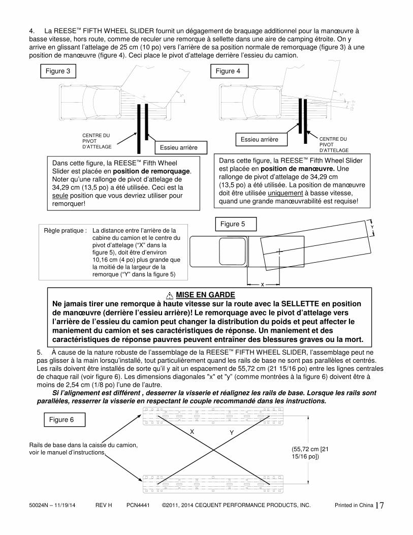
Dans cette figure, la REESE™ Fifth Wheel Slider est placée en position de remorquage. Noter qu’une rallonge de pivot d’attelage de 34,29 cm (13,5 po) a été utilisée. Ceci est la seule position que vous devriez utiliser pour remorquer!
Dans cette figure, la REESE™ Fifth Wheel Sliderest placée en position de manœuvre. Une rallonge de pivot d’attelage de 34,29 cm (13,5 po) a été utilisée. La position de manœuvre doit être utilisée uniquement à basse vitesse, quand une grande manœuvrabilité est requise!
5. À cause de la nature robuste de l’assemblage de la REESE™ FIFTH WHEEL SLIDER, l’assemblage peut ne pas glisser à la main lorsqu’installé, tout particulièrement quand les rails de base ne sont pas parallèles et centrés. Les rails doivent être installés de sorte qu’il y ait un espacement de 55,72 cm (21 15/16 po) entre les lignes centrales de chaque rail (voir figure 6). Les dimensions diagonales "x" et "y” (comme montrées à la figure 6) doivent être à moins de 2,54 cm (1/8 po) l’une de l’autre.
Si l’alignement est différent , desserrer la visserie et réalignez les rails de base. Lorsque les rails sont parallèles, resserrer la visserie en respectant le couple recommandé dans les instructions.
4. La REESE™ FIFTH WHEEL SLIDER fournit un dégagement de braquage additionnel pour la manœuvre à basse vitesse, hors route, comme de reculer une remorque à sellette dans une aire de camping étroite. On y arrive en glissant l’attelage de 25 cm (10 po) vers l’arrière de sa position normale de remorquage (figure 3) à une position de manœuvre (figure 4). Ceci place le pivot d’attelage derrière l’essieu du camion.
MISE EN GARDENe jamais tirer une remorque à haute vitesse sur la route avec la SELLETTE en position de manœuvre (derrière l’essieu arrière)! Le remorquage avec le pivot d’attelage vers l’arrière de l’essieu du camion peut changer la distribution du poids et peut affecter le maniement du camion et ses caractéristiques de réponse. Un maniement et des caractéristiques de réponse pauvres peuvent entraîner des blessures graves ou la mort.
Figure 6
Rails de base dans la caisse du camion, voir le manuel d’instructions.
X Y
Figure 3
Essieu arrièreEssieu arrière
Figure 4
CENTRE DU PIVOT D’ATTELAGE
CENTRE DU PIVOT D’ATTELAGE
(55,72 cm [21 15/16 po])
Règle pratique : La distance entre l’arrière de la cabine du camion et le centre du pivot d’attelage (“X” dans la figure 5), doit être d’environ 10,16 cm (4 po) plus grande que la moitié de la largeur de la remorque (“Y” dans la figure 5)
Figure 5
50024N – 11/19/14 REV H PCN4441 ©2011, 2014 CEQUENT PERFORMANCE PRODUCTS, INC. Printed in China 18
Étiquettes de sécurité face au côté conducteur.
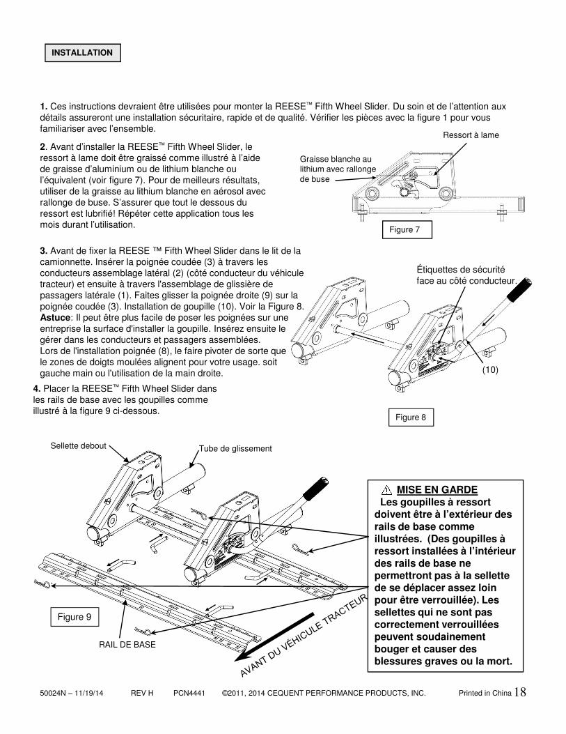
3. Avant de fixer la REESE ™ Fifth Wheel Slider dans le lit de la camionnette. Insérer la poignée coudée (3) à travers les conducteurs assemblage latéral (2) (côté conducteur du véhicule tracteur) et ensuite à travers l'assemblage de glissière de passagers latérale (1). Faites glisser la poignée droite (9) sur la poignée coudée (3). Installation de goupille (10). Voir la Figure 8.Astuce: Il peut être plus facile de poser les poignées sur une entreprise la surface d'installer la goupille. Insérez ensuite legérer dans les conducteurs et passagers assemblées.Lors de l'installation poignée (8), le faire pivoter de sorte que le zones de doigts moulées alignent pour votre usage. soit gauche main ou l'utilisation de la main droite.
4. Placer la REESE™ Fifth Wheel Slider dans les rails de base avec les goupilles comme illustré à la figure 9 ci-dessous.
Figure 9
Figure 8
`
2. Avant d’installer la REESE™ Fifth Wheel Slider, le ressort à lame doit être graissé comme illustré à l’aide de graisse d’aluminium ou de lithium blanche ou l’équivalent (voir figure 7). Pour de meilleurs résultats, utiliser de la graisse au lithium blanche en aérosol avec rallonge de buse. S’assurer que tout le dessous du ressort est lubrifié! Répéter cette application tous les mois durant l’utilisation.
1. Ces instructions devraient être utilisées pour monter la REESE™ Fifth Wheel Slider. Du soin et de l’attention aux détails assureront une installation sécuritaire, rapide et de qualité. Vérifier les pièces avec la figure 1 pour vous familiariser avec l’ensemble.
INSTALLATION
MISE EN GARDELes goupilles à ressort
doivent être à l’extérieur des rails de base comme illustrées. (Des goupilles à ressort installées à l’intérieur des rails de base ne permettront pas à la sellette de se déplacer assez loin pour être verrouillée). Les sellettes qui ne sont pas correctement verrouillées peuvent soudainement bouger et causer des blessures graves ou la mort.
Tube de glissementSellette debout
Graisse blanche au lithium avec rallonge de buse
Ressort à lame
Figure 7
RAIL DE BASE
(10)
50024N – 11/19/14 REV H PCN4441 ©2011, 2014 CEQUENT PERFORMANCE PRODUCTS, INC. Printed in China
(3)
19
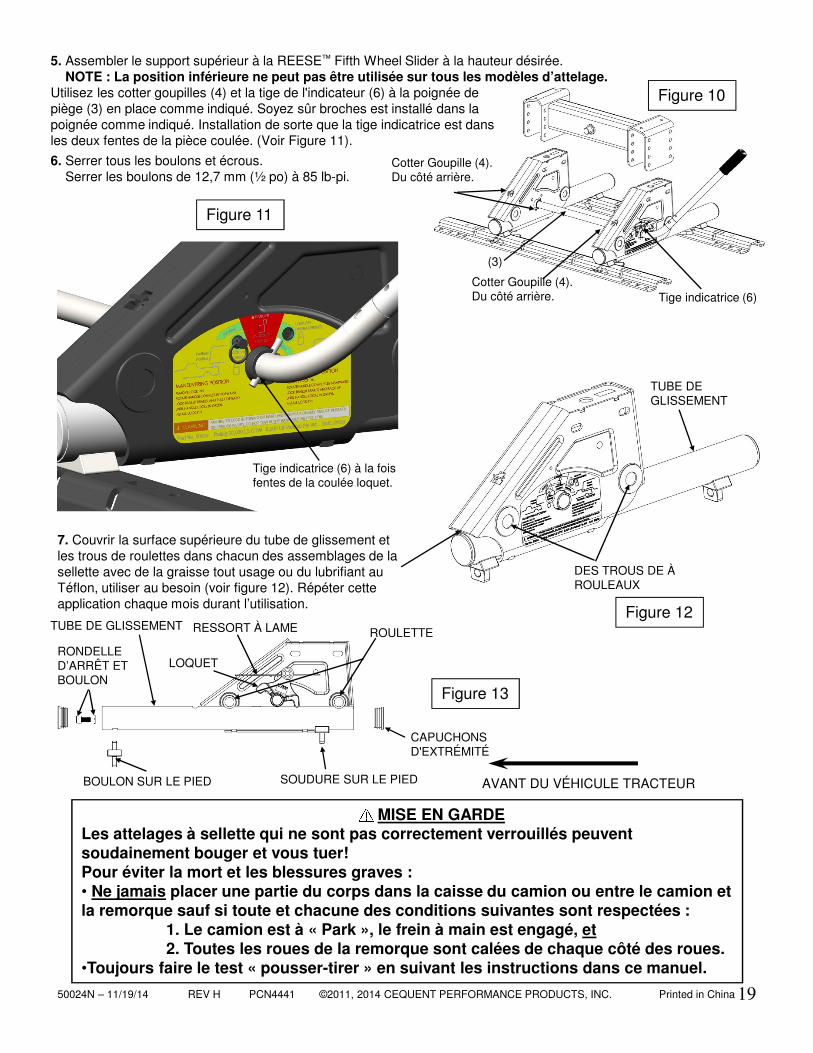
5. Assembler le support supérieur à la REESE™ Fifth Wheel Slider à la hauteur désirée. NOTE : La position inférieure ne peut pas être utilisée sur tous les modèles d’attelage.
Utilisez les cotter goupilles (4) et la tige de l'indicateur (6) à la poignée de piège (3) en place comme indiqué. Soyez sûr broches est installé dans la poignée comme indiqué. Installation de sorte que la tige indicatrice est dans les deux fentes de la pièce coulée. (Voir Figure 11).
Figure 13
7. Couvrir la surface supérieure du tube de glissement et les trous de roulettes dans chacun des assemblages de la sellette avec de la graisse tout usage ou du lubrifiant au Téflon, utiliser au besoin (voir figure 12). Répéter cette application chaque mois durant l’utilisation.
Figure 12
Figure 10
6. Serrer tous les boulons et écrous. Serrer les boulons de 12,7 mm (½ po) à 85 lb-pi.
Cotter Goupille (4).Du côté arrière. Tige indicatrice (6)
ROULETTETUBE DE GLISSEMENT
RONDELLE D’ARRÊT ET BOULON
CAPUCHONS D'EXTRÉMITÉ
RESSORT À LAME
LOQUET
SOUDURE SUR LE PIEDBOULON SUR LE PIED
Tige indicatrice (6) à la foisfentes de la coulée loquet.
Figure 11
Cotter Goupille (4).Du côté arrière.
DES TROUS DE À ROULEAUX
TUBE DE GLISSEMENT
MISE EN GARDELes attelages à sellette qui ne sont pas correctement verrouillés peuvent soudainement bouger et vous tuer!Pour éviter la mort et les blessures graves :• Ne jamais placer une partie du corps dans la caisse du camion ou entre le camion et la remorque sauf si toute et chacune des conditions suivantes sont respectées :
1. Le camion est à « Park », le frein à main est engagé, et2. Toutes les roues de la remorque sont calées de chaque côté des roues.
•Toujours faire le test « pousser-tirer » en suivant les instructions dans ce manuel.
AVANT DU VÉHICULE TRACTEUR
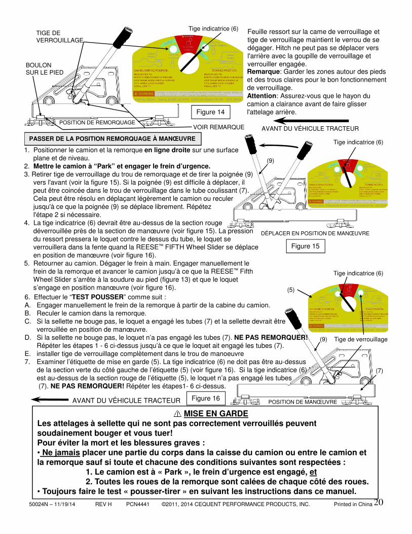
50024N – 11/19/14 REV H PCN4441 ©2011, 2014 CEQUENT PERFORMANCE PRODUCTS, INC. Printed in China
(5)
(9)
(7)
(9)
20
Feuille ressort sur la came de verrouillage et tige de verrouillage maintient le verrou de se dégager. Hitch ne peut pas se déplacer vers l'arrière avec la goupille de verrouillage et verrouiller engagée.
AVANT DU VÉHICULE TRACTEURPOSITION DE REMORQUAGE
Figure 14
1. Positionner le camion et la remorque en ligne droite sur une surface plane et de niveau.
2. Mettre le camion à “Park” et engager le frein d’urgence. 3. Retirer tige de verrouillage du trou de remorquage et de tirer la poignée (9)
vers l'avant (voir la figure 15). Si la poignée (9) est difficile à déplacer, il peut être coincée dans le trou de verrouillage dans le tube coulissant (7). Cela peut être résolu en déplaçant légèrement le camion ou reculer jusqu'à ce que la poignée (9) se déplace librement. Répétez l'étape 2 si nécessaire.
4. La tige indicatrice (6) devrait être au-dessus de la section rougedéverrouillée près de la section de manœuvre (voir figure 15). La pression du ressort pressera le loquet contre le dessus du tube, le loquet se verrouillera dans la fente quand la REESE™ FIFTH Wheel Slider se déplace en position de manœuvre (voir figure 16).
5. Retourner au camion. Dégager le frein à main. Engager manuellement le frein de la remorque et avancer le camion jusqu’à ce que la REESE™ FifthWheel Slider s’arrête à la soudure au pied (figure 13) et que le loquet s’engage en position manœuvre (voir figure 16).
DÉPLACER EN POSITION DE MANŒUVRE
Figure 15
6. Effectuer le “TEST POUSSER” comme suit :A. Engager manuellement le frein de la remorque à partir de la cabine du camion.B. Reculer le camion dans la remorque.C. Si la sellette ne bouge pas, le loquet a engagé les tubes (7) et la sellette devrait être
verrouillée en position de manœuvre.D. Si la sellette ne bouge pas, le loquet n’a pas engagé les tubes (7). NE PAS REMORQUER!
Répéter les étapes 1 - 6 ci-dessus jusqu’à ce que le loquet ait engagé les tubes (7).E. installer tige de verrouillage complètement dans le trou de manoeuvre7. Examiner l’étiquette de mise en garde (5). La tige indicatrice (6) ne doit pas être au-dessus
de la section verte du côté gauche de l’étiquette (5) (voir figure 16). Si la tige indicatrice (6) est au-dessus de la section rouge de l’étiquette (5), le loquet n’a pas engagé les tubes(7). NE PAS REMORQUER! Répéter les étapes1- 6 ci-dessus.
PASSER DE LA POSITION REMORQUAGE À MANŒUVRE
POSITION DE MANŒUVRE Figure 16
Tige indicatrice (6)
Tige indicatrice (6)
Tige indicatrice (6)
AVANT DU VÉHICULE TRACTEUR
MISE EN GARDELes attelages à sellette qui ne sont pas correctement verrouillés peuvent soudainement bouger et vous tuer!Pour éviter la mort et les blessures graves :• Ne jamais placer une partie du corps dans la caisse du camion ou entre le camion et la remorque sauf si toute et chacune des conditions suivantes sont respectées :
1. Le camion est à « Park », le frein d’urgence est engagé, et2. Toutes les roues de la remorque sont calées de chaque côté des roues.
• Toujours faire le test « pousser-tirer » en suivant les instructions dans ce manuel.
Remarque: Garder les zones autour des pieds et des trous claires pour le bon fonctionnement de verrouillage.Attention: Assurez-vous que le hayon du camion a clairance avant de faire glisser l'attelage arrière.
BOULON SUR LE PIED
VOIR REMARQUE
TIGE DE VERROUILLAGE
Tige de verrouillage
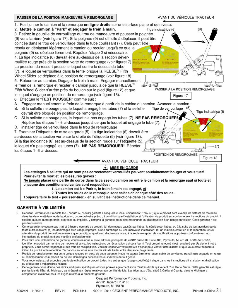
50024N – 11/19/14 REV H PCN4441 ©2011, 2014 CEQUENT PERFORMANCE PRODUCTS, INC. Printed in China
MISE EN GARDELes attelages à sellette qui ne sont pas correctement verrouillés peuvent soudainement bouger et vous tuer!Pour éviter la mort et les blessures graves :Ne jamais placer une partie du corps dans la caisse du camion ou entre le camion et la remorque sauf si toute et chacune des conditions suivantes sont respectées :
1. Le camion est à « Park », le frein à main est engagé, et2. Toutes les roues de la remorque sont calées de chaque côté des roues.
Toujours faire le test « pousser-tirer » en suivant les instructions dans ce manuel.
(5)
(7)
(9)
21
PASSER DE LA POSITION MANŒUVRE À REMORQUAGE
PASSER À LA POSITION REMORQUAGE
AVANT DU VÉHICULE TRACTEUR
Figure 17
POSITION DE REMORQUAGE
Tige indicatrice (6)
Figure 18
Tige indicatrice (6)
• Cequent Performance Products Inc. ( "nous" ou "nous") garantit à l'acquéreur initial uniquement (" Vous ") que le produit sera exempt de défauts de matériaudans les deux matériaux et de fabrication, usure ordinaire prévu ; à condition que l'installation et l'utilisation du produit est conforme aux instructions du produit. Il n'existe aucune autre garantie, expresse ou implicite, y compris la garantie de qualité marchande ou d'adéquation à un usage particulier. Cette garantie n'estpas transférable.
• Cette garantie ne couvre pas : (a) et à l'usure normale du produit; (b) dommages causés par l'abus, la négligence, l'abus, ou à la suite de tout accident ou de toute autre manière; (c) les dommages d'un usage impropre, à une surcharge ou une mauvaise installation; (d) un mauvais entretien et la réparation; et (e) altération du produit de quelque manière que ce soit par quelqu'un d'autre que nous, à la seule exception de modifications apportées conformément aux instructions du produit et d'une manière professionnelle.
• Pour faire une réclamation de garantie, contactez-nous à notre adresse principale de 47912 drisse Dr. Suite 100, Plymouth, MI 48170, 1-800 -521-0510, identifier le produit par numéro de modèle, et suivez les instructions de réclamation qui sera fourni. Tout produit retourné c'est remplacé par Us devient notrepropriété. Vous serez responsable des frais de réexpédition. Veuillez conserver votre preuve d'achat pour vérifier date d'achat et que vous êtes l'acquéreurinitial. Le produit et la réception d'achat doivent nous être fournis afin de traiter votre demande de garantie.
• Produit de remplacement est votre unique recours en vertu de cette garantie. Nous ne saurait être tenu responsable de service ou travail frais engagés en retraitou remplacement d'un produit ou de tout dommages accessoires ou indirects de tout genre.
• Vous reconnaissez et acceptez que toute utilisation du produit à des fins autres que l'usage spécifié(s) indiqué dans les instructions d'installation et d'utilisationdu produit est à vos propres risques.
• Cette garantie vous donne des droits juridiques spécifiques et vous pouvez également avoir d'autres droits qui varient d'un état à l'autre. Cette garantie est régiepar les lois de l'État du Michigan, sans égard aux règles relatives aux conflits de lois. Les tribunaux d'état situé à Oakland County, dans le Michigan a compétence exclusive pour les litiges relatifs à la présente garantie.
GARANTIE À VIE LIMITÉE
Cequent Performance Products, Inc.47912 Halyard Dr, #100Plymouth, MI 48170
AVANT DU VÉHICULE TRACTEUR
Tige de verrouillage
1. Positionner le camion et la remorque en ligne droite sur une surface plane et de niveau.2. Mettre le camion à “Park” et engager le frein à main.3. Retirez la goupille de verrouillage du trou de manoeuvre et pousser la poignée (9) vers l'arrière (voir figure 17). Si la poignée (9) est difficile à déplacer, il peut être coincée dans le trou de verrouillage dans le tube coulissant (7). Cela peut être résolu en déplaçant légèrement le camion ou reculer jusqu'à ce que la poignée (9) se déplace librement. Répétez l'étape 2 si nécessaire.4. La tige indicatrice (6) devrait être au-dessus de la section déver-rouillée rouge près de la section verte de remorquage (voir figure17). La pression du ressort presse le loquet contre le dessus du tube(7), le loquet se verrouillera dans la fente lorsque la REESE™ FifthWheel Slider se déplace à la position de remorquage (voir figure 18).5. Retourner au camion. Dégager le frein à main. Engager manuellement le frein de la remorque et reculer le camion jusqu’à ce que la REESE™
Fifth Wheel Slider s’arrête près du boulon sur le pied (figure 12) et que le loquet s’engage en position de remorquage (voir figure 18). 6. Effectuer le “TEST POUSSER” comme suit :A. Engager manuellement le frein de la remorque à partir de la cabine du camion. Avancer le camion.B. Si la sellette ne bouge pas, le loquet a engagé les tubes (7) et la sellette
devrait être bloquée en position de remorquage.C. Si la sellette ne bouge pas, le loquet n’a pas engagé les tubes (7). NE PAS REMORQUER!
Répéter les étapes 1 - 6 ci-dessus jusqu’à ce que le loquet ait engagé le tube (7).D. installer tige de verrouillage dans le trou de remorquage7. Examiner l’étiquette de mise en garde (5). La tige indicatrice (6) devrait être au-dessus de la section verte sur la droite de l’étiquette (5) (voir figure 18). Si la tige indicatrice (6) est au-dessus de la section rouge sur l’étiquette (5), le loquet n’a pas engagé les tubes (7). NE PAS REMORQUER! Répéter les étapes 1- 6 ci-dessus.